Installation Manual - Platt Electric Supply
Installation Manual - Platt Electric Supply
Installation Manual - Platt Electric Supply

You also want an ePaper? Increase the reach of your titles
YUMPU automatically turns print PDFs into web optimized ePapers that Google loves.
HAI UPB Wall Switch and Auxiliary Switch<br />
<strong>Installation</strong> and Operating Instructions<br />
For the following Models:<br />
35A00-1 HAI 600W Dimmer Switch, 35A00-3 HAI 600W Non-Dimming Switch (collectively referred to as HAI UPB Wall<br />
Switch, in this document), and 37A00-1 HAI Auxiliary Switch<br />
READ THESE INSTRUCTIONS BEFORE INSTALLING DEVICE<br />
This HAI UPB Wall Switch and Auxiliary Switch is intended for installation in accordance with the National <strong>Electric</strong>al Code and<br />
local codes and regulations. It is recommended that a qualified electrician perform this installation. Retain these instructions for<br />
reference.<br />
To reduce the risk of overheating and possible damage to other equipment, when configured as dimming-capable, do not install to<br />
control a receptacle, a motor-operated appliance, a fluorescent lighting fixture, or a transformer-supplied appliance.<br />
This product is for indoor use only. Connect only copper or copper clad wire to this device.<br />
Important Notes Prior To <strong>Installation</strong><br />
1. All HAI UPB Wall Switches require a neutral (white) connection wire.<br />
2. Be sure that all power to the load has been disconnected by turning off the circuit breaker. Installing an HAI UPB Wall Switch<br />
or Auxiliary Switch with power on may expose you to dangerous voltage and may damage the device.<br />
HAI UPB Wall Switch Overview<br />
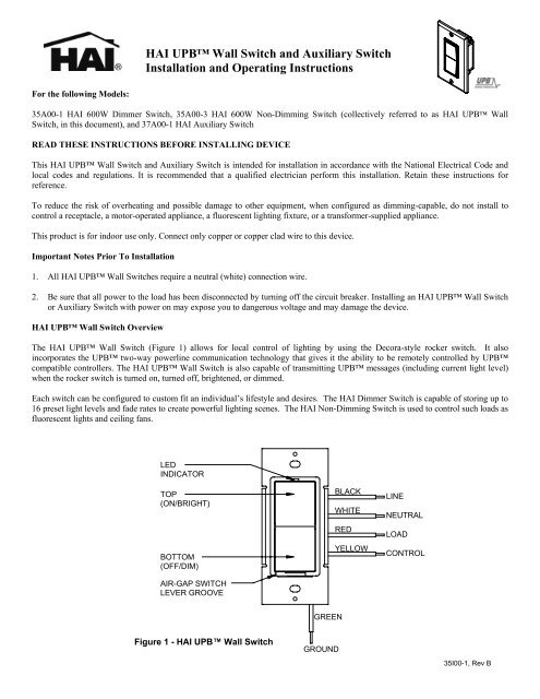
The HAI UPB Wall Switch (Figure 1) allows for local control of lighting by using the Decora-style rocker switch. It also<br />
incorporates the UPB two-way powerline communication technology that gives it the ability to be remotely controlled by UPB<br />
compatible controllers. The HAI UPB Wall Switch is also capable of transmitting UPB messages (including current light level)<br />
when the rocker switch is turned on, turned off, brightened, or dimmed.<br />
Each switch can be configured to custom fit an individual’s lifestyle and desires. The HAI Dimmer Switch is capable of storing up to<br />
16 preset light levels and fade rates to create powerful lighting scenes. The HAI Non-Dimming Switch is used to control such loads as<br />
fluorescent lights and ceiling fans.<br />
LED<br />
INDICATOR<br />
TOP<br />
(ON/BRIGHT)<br />
BOTTOM<br />
(OFF/DIM)<br />
AIR-GAP SWITCH<br />
LEVER GROOVE<br />
BLACK<br />
WHITE<br />
RED<br />
YELLOW<br />
LINE<br />
NEUTRAL<br />
LOAD<br />
CONTROL<br />
GREEN<br />
Figure 1 - HAI UPB Wall Switch<br />
GROUND<br />
35I00-1, Rev B
HAI Auxiliary Switch Overview<br />
The 37A00-1 HAI Auxiliary Switch (Figure 2) is an optional companion device used with the HAI UPB Wall Switch for multi-way<br />
circuits. The HAI Auxiliary Switch has a Decora-style rocker switch that controls the lighting load in the exact same manner as the<br />
Decora-style rocker switch on the HAI UPB Wall Switch.<br />
LED<br />
INDICATOR<br />
TOP<br />
(ON/BRIGHT)<br />
BOTTOM<br />
(OFF/DIM)<br />
BLACK<br />
GRAY<br />
BLUE<br />
YELLOW<br />
LINE<br />
*NEUTRAL<br />
(FOR RED INDICATOR)<br />
*NEUTRAL<br />
(FOR BLUE INDICATOR)<br />
CONTROL<br />
Figure 2 – HAI Auxiliary Switch<br />
Changing Switch Color<br />
The color of the HAI UPB Wall Switch and Auxiliary Switch may be changed to<br />
complement the interior décor. The HAI UPB Wall Switch and Auxiliary Switch<br />
is supplied with a white switch plate. Additional colors are available; contact your<br />
HAI distributor for more information. When changing the switch plate, make sure<br />
that the switch is disconnected from all power, and proceed as follows:<br />
1. The switch plate attaches to the HAI UPB Wall Switch and Auxiliary Switch<br />
with two latches on the right and two on the left. Using a small-bladed<br />
screwdriver, gently depress the upper and lower latch on one side while lifting<br />
up on the plate. Once the latches are released on one side, remove the switch<br />
plate from the other side.<br />
2. Align the latches of the new switch plate to the openings on the mounting plate<br />
and gently snap into place.<br />
Figure 3 – Changing Switch Color<br />
INSTALLATION INSTRUCTIONS<br />
The HAI UPB Wall Switch is wired directly to the lighting circuit and can be controlled by adding one or more optional HAI<br />
Auxiliary Switches producing multi-way circuits. Multi-way circuits make it possible for a group of switches to control the same light<br />
or set of lights. This section will illustrate how to make the connections.<br />
Notes:<br />
1. Refer to Figures 1 and Figure 2 to determine the wire colors for each connection.<br />
2. All HAI UPB Wall Switches require a neutral (white) connection.<br />
3. The Line (black) wire must be accessible for the installation of all HAI Auxiliary Switches. This wire may be connected to either<br />
phase of the 120/240V supply. The blue and/or gray wire on the HAI Auxiliary Switch can be connected to either earth ground or<br />
neutral. The blue and/or gray wire is only used to light the LED on the switch. This LED only indicates that power is applied and<br />
serves as a night-light. Connect the blue wire only to light the LED blue. Connect the gray wire only to light the LED red.<br />
Connect both the blue wire and the gray wire to light the LED magenta.
Air-Gap Switch Lever<br />
The HAI UPB Wall Switch has an air-gap switch lever that will remove all power from the load for safe<br />
switch installation and light bulb replacement. To activate the air-gap switch, using your fingernail, pry open<br />
the lever at the groove (Figure 1). Swing the lever fully open so that it is perpendicular to the bottom rim<br />
(Figure 4). After servicing, push the lever fully closed so that it is parallel to the bottom rim. The lever<br />
must be pushed fully closed for normal operation.<br />
Figure 4 – Air-Gap Switch Lever<br />
<strong>Installation</strong> Procedure<br />
1. Be sure that all power to the load has been disconnected by turning off the circuit breaker.<br />
2. If applicable, remove the faceplate from the existing wall switch, remove the existing wall switch from the wall box, and<br />
disconnect the wires from the existing wall switch. Identify the “Line”, "Neutral", "Load" and “Traveler” (if applicable) wires.<br />
3. Be sure that the air-gap switch lever on the HAI UPB Wall Switch is fully open.<br />
4. Remove ¾” of insulation from each of the wires on the HAI UPB Wall Switch. Install the HAI UPB Wall Switch by<br />
connecting wires per wiring configuration shown in Figure 5.<br />
5. Install any optional HAI Auxiliary Switch per wiring configuration shown in Figure 5.<br />
6. After all connections have been made, be certain that all wire connectors are firmly attached and there is no exposed copper.<br />
7. Gently place the wires and HAI UPB Wall Switch into the wall box with the LED at the top of device. Using the supplied<br />
screws, attach the HAI UPB Wall Switch to the wall box.<br />
8. Before installing the faceplate, restore power to the circuit, and then fully close the air-gap switch lever.<br />
9. After testing the HAI UPB Wall Switch and Auxiliary Switch for proper local operation (Table 2 and Table 3), install a<br />
Decora-style faceplate over each switch.<br />
LINE<br />
37A00 (OPTIONAL)<br />
AUXILIARY SWITCH<br />
37A00 (OPTIONAL)<br />
AUXILIARY SWITCH<br />
35A00<br />
HAI Wall Switch<br />
BLACK BLACK BLACK<br />
YELLOW<br />
YELLOW<br />
YELLOW<br />
Line 120VAC, 60Hz<br />
WHITE<br />
RED<br />
*BLUE AND/OR GRAY<br />
*BLUE AND/OR GRAY<br />
GREEN<br />
NEUTRAL<br />
*CONNECTING THE BLUE AND/OR GRAY WIRE TO NEUTRAL SETS THE COLOR OF THE LED INDICATOR.<br />
CONNECT BLUE FOR BLUE INDICATOR, GRAY FOR RED INDICATOR, OR BOTH FOR MAGENTA INDICATOR.<br />
BLUE AND/OR GRAY WIRE MAY BE CONNECTED TO NEUTRAL OR EARTH GROUND. NEUTRAL IS RECOMMENDED.<br />
Figure 5 – Wiring Diagram
HAI UPB Wall Switch De-Rating<br />
In two-gang installations, there is no need to de-rate the 35A00-1 or 35A00-3. In three-gang installations, each switch must be derated<br />
from 600W to 500W.<br />
Model Device Maximum Load Next to One Dimmer Next to Two Dimmers<br />
35A00-1 600W 600W 500W<br />
35A00-3 600W 600W 500W<br />
Table 1 – HAI Wall Switch De-Rating<br />
HAI DIMMER SWITCH OPERATION<br />
The HAI Dimmer Switch has many configurable items that can be set using the UPB UPStart configuration software. The following<br />
describes the operation of the HAI Dimmer Switch in its factory default configuration.<br />
Local Rocker Switch Operation<br />
The HAI Dimmer Switch has a Decora-style rocker switch that can be used to control the lighting load as follows.<br />
Rocker Event Top Rocker Bottom Rocker<br />
Single-Tap Brightens the light to 100% (on) at a 0.8 second fade rate. Fade the light to 0% (off) at a 1.6 second fade rate.<br />
Double-Tap Snaps the light to 100% (on). Snaps the light to 0% (off).<br />
Hold Starts fading (brightening) the light towards 100% at a<br />
3.3 second fade rate.<br />
Starts fading (dimming) the light towards 0% at a 3.3<br />
second fade rate.<br />
Release Stops brightening the light. Stops dimming the light.<br />
Table 2 - HAI UPB Dimmer Switch Local Operation<br />
HAI NON-DIMMING SWITCH OPERATION<br />
The HAI Non-Dimming Switch has many configurable items that can be set using the UPB UPStart configuration software. The<br />
following describes the operation of the HAI Non-Dimming Switch in its factory default configuration.<br />
Local Rocker Switch Operation<br />
The HAI Non-Dimming Switch has a Decora-style rocker switch that can be used to control the load as follows.<br />
Rocker Event Top Rocker Bottom Rocker<br />
Single-Tap Turns the load on. Turns the load off.<br />
LED Indicator<br />
Table 3 – HAI Non-Dimming Switch Local Operation<br />
The HAI UPB Wall Switch comes equipped with a multi-color LED indicator that is normally lit to blue when the load is off. The<br />
LED will turn off when the load is turned on or set to any level above 0%.<br />
If used, the LED in the HAI Auxiliary Switch is always lit.<br />
HAI AUXILIARY SWITCH OPERATION<br />
The HAI UPB Wall Switch can be connected to one or more HAI Auxiliary Switches producing multi-way lighting circuits. Each<br />
HAI Auxiliary Switch has a Decora-style rocker switch that controls the lighting load in the exact same manner as the Decora-style<br />
rocker switch on the connected HAI UPB Wall Switch, as previously described. When connected, the LED remains continually on<br />
at all times while power is applied.
Setup Mode<br />
To configure the HAI UPB Wall Switch using an HAI controller or a PC running the UPB UPStart configuration software, it<br />
must be put into Setup Mode as follows:<br />
Step Operation<br />
1 Tap the rocker switch quickly 5 times<br />
2 The HAI UPB Wall Switch will flash the lighting load one time and blink its LED blue to indicate that it is in Setup<br />
Mode. Note: the switch will automatically exit Setup mode after 5 minutes.<br />
Reset to Factory Default Settings<br />
To reset the HAI UPB Wall Switch to factory default settings:<br />
Step Operation<br />
1 On the HAI UPB Wall Switch that you want to reset to factory default, tap the rocker switch quickly 5 times.<br />
2 The HAI UPB Wall Switch will flash the lighting load one time and blink its LED blue to indicate that it is ready to be<br />
reset.<br />
3 Tap the rocker switch quickly 10 times to reset to factory default setting.<br />
4 The HAI UPB Wall Switch will flash the lighting load one time and blink its LED red to indicate that it has been reset.<br />
5 Tap the rocker switch twice to stop the LED from blinking.<br />
SPECIFICATIONS<br />
Model Number 35A00-1 35A00-3<br />
Incandescent Loads Dimming Yes Yes (configurable)<br />
Inductive Loads Dimming Yes Yes (configurable)<br />
Florescent Loads Non-Dimming Yes (configurable) Yes<br />
Power Maximum Dimming 600W / 600VA 600W / 600VA<br />
Current Maximum Non-Dimming 5A 5A<br />
Connections 18 GA 18 GA<br />
LED Indicator Yes Yes<br />
Dimensions 4.1 x 1.75 x 1.45 4.1 x 1.75 x 1.45<br />
Weight 0.25 lb. 0.25 lb.<br />
Mounting Standard J Box Standard J Box<br />
Input Power 120 ± 12 VAC 120 ± 12 VAC<br />
Input Frequency 60 ± 3 Hz 60 ± 3 Hz<br />
Operating Temperature -40 °F to 104 °F -40 °F to 104 °F<br />
Note: It is normal for this switch to make a slight buzzing sound during operation. It is also normal for the switch and wall plate to<br />
feel warm to the touch.<br />
LIMITED WARRANTY<br />
HAI warrants this product against defects in material and workmanship, under normal use and service, for a period of two (2) years from the date of<br />
purchase. During the warranty period, HAI will repair or replace, at its sole option, if this product fails due to defect. This warranty does not cover the<br />
cost of removal or reinstallation of any product. This warranty does not cover failure caused by normal wear, damage to the product while in<br />
your possession (other than damage caused by defect or malfunction), or by its improper installation, including failure to follow the written<br />
installation and operation instructions, alterations, misuse, or abuse. The remedies provided for in this warranty are the sole and exclusive<br />
remedies thereof. In no event shall HAI be liable for incidental expenses or consequential loss or damages. For the complete HAI Warranty for USA<br />
policy, see the HAI web site at www.homeauto.com.<br />
Any implied warranties, including warranties of merchantability and fitness for particular use or purpose are limited to a period of two (2)<br />
years from purchase date. This warranty gives you specific legal rights, and you may have other legal rights, which vary from state to state. Some<br />
limitations may not apply to you.<br />
For warranty and repair service within the continental United States, send defective unit carefully packaged, postage prepaid, along with description of<br />
trouble, name, return address, and phone number to: HAI, Repair Department, 4330 Michoud Blvd, New Orleans, LA, 70129. HAI will pay return<br />
shipping charges via normal ground service.<br />
Outside of the continental United States: Contact an Authorized Distributor for repair/replacement instructions.