Pressure Switches L&G Bulletin.pdf - Pilgrim Instrument
Pressure Switches L&G Bulletin.pdf - Pilgrim Instrument
Pressure Switches L&G Bulletin.pdf - Pilgrim Instrument

You also want an ePaper? Increase the reach of your titles
YUMPU automatically turns print PDFs into web optimized ePapers that Google loves.
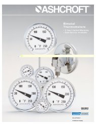
G and L TEMPERATURE SWITCHES<br />
Temperature <strong>Switches</strong><br />
G- and L-Series temperature<br />
switches feature a SAMA Class II<br />
vapor pressure thermal system.<br />
This system provides quick,<br />
accurate response to process<br />
temperature changes with negligible<br />
ambient temperature effects.<br />
This is inherent in the design due to<br />
the precise relationship between<br />
temperature and pressure according<br />
to the vapor pressure laws. A<br />
wide selection of sensing bulb and<br />
armored capillary lengths are<br />
available. The vapor pressure<br />
system design features small bulb<br />
sizes, making installation easy and<br />
cost-effective.<br />
All models feature ±1 percent of<br />
span setpoint repeatability with<br />
very high overtemperature ratings.<br />
These standard designs perform<br />
well in applications where shock<br />
and vibration could be a problem<br />
and should be used with Ashcroft<br />
thermowells for bulb protection and<br />
ease of installation and maintenance.<br />
Thermowells<br />
Thermowells must be used on any<br />
application where the stem of the<br />
temperature switch may be exposed<br />
to pressure, corrosive fluids<br />
or high velocity. Additionally, the<br />
use of a thermowell permits instrument<br />
interchange or calibration<br />
check without disturbing or closing<br />
down the process.<br />
Ashcroft temperature switches<br />
have bulb diameters to match 3 / 8˝<br />
nominal bore thermowells. The<br />
bulbs have a sensitive portion<br />
length of 2 1 / 4˝ which can be used<br />
with 2 1 / 2˝ “U” dimensioned<br />
thermowells or longer. For maximum<br />
accuracy, a thermowell “U”<br />
dimension should be selected to<br />
permit complete immersion of the<br />
sensitive portion plus 1˝ when<br />
measuring the temperature of<br />
liquids; an extra 3˝ should be<br />
allowed when measuring the<br />
temperature of gases.<br />
Thermowell bushings should be<br />
used with remote mount temperature<br />
switches. We recommend the<br />
standard 3˝ bulb and code 69<br />
Series bushings for use with any<br />
thermowell “U” dimension. A split<br />
rubber grommet allows easy<br />
installation and “S” dimension<br />
adjustment.<br />
TEMPERATURE RANGE SELECTION<br />
Nominal Range<br />
NOTES:<br />
1. <strong>Switches</strong> may generally be set between 15% and 100%<br />
of nominal range on increasing or decreasing<br />
temperature. Consult factory for applications where<br />
setpoints must be lower.<br />
2. All deadbands are given in O F.<br />
Approximate Deadband (2)<br />
Max. LTA-GTA (3) LTS-GTS (4) LTD-GTD (4)<br />
°F °C<br />
Temp.<br />
Switch Element<br />
°F J, H G J, H K, F P GG JJ, HH KK,FF PP<br />
-40 to 60 -40 to16 400 18-90 4.0-10 9.0-18 1.5-3 2-5 4-10 9.0-18 1.5-3 2-5<br />
0 to 100 -20 to 40 400 30-90 5.0-15 10-30 1.5.5 3-7 5-15 10-30 1.5-4.5 3-7<br />
75 to 205 20 to 95 400 34-120 6.0-18 10-34 3-5.5 3-8 6-18 10-34 3-5.5 3-8<br />
150 to 260 65 to125 400 25-100 3-13 9.0-25 1.5-4 3-7 3-13 9.0-25 1.5-4 3-7<br />
235 to 375 110 to 190 500 35-130 6-19 10-35 2-5.5 3-8 6-17 10-35 2-5.5 3-8<br />
350 to 525 (5) 175 to 275 700 40-165 5-27 15-40 3-7 3.5-11 5-27 15-40 3-7 3.5-11<br />
500 to 750 (5)(6) 260 to 400 900 50-200 20-36 36-60 5-10 6-21 20-36 36-60 5-10 6-21<br />
3. Deadbands for LTA and GTA are<br />
adjustable between the values shown.<br />
4. Deadbands for LTS, GTS, LTD and GTD<br />
models are fixed within the range of values shown.<br />
Manufacturing and parts variances result in variation<br />
from one unit to another.<br />
5. Not available with 2 3 /4”stem<br />
6. Available with remote mount thermal system only.<br />
6