Pressure Switches L&G Bulletin.pdf - Pilgrim Instrument
Pressure Switches L&G Bulletin.pdf - Pilgrim Instrument
Pressure Switches L&G Bulletin.pdf - Pilgrim Instrument

You also want an ePaper? Increase the reach of your titles
YUMPU automatically turns print PDFs into web optimized ePapers that Google loves.
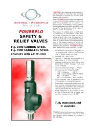
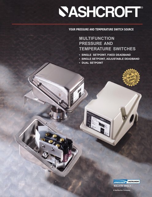
YOUR PRESSURE AND TEMPERATURE SWITCH SOURCE<br />
MULTIFUNCTION<br />
PRESSURE AND<br />
TEMPERATURE SWITCHES<br />
• SINGLE SETPOINT, FIXED DEADBAND<br />
• SINGLE SETPOINT, ADJUSTABLE DEADBAND<br />
• DUAL SETPOINT<br />
BULLETIN SWGL-1<br />
A Halliburton Company<br />
13
PRODUCT INFORMATION<br />
Dresser Control <strong>Instrument</strong> Operation<br />
is a supplier of highly reliable<br />
Ashcroft ® switches and controls for<br />
industrial and process applications.<br />
We stress total value to the customer.<br />
We begin with rock-solid<br />
designs, matching the most appropriate<br />
technology with the safety<br />
and reliability requirements of the<br />
applications. Materials of construction<br />
are specified to the exacting<br />
standards of Dresser <strong>Instrument</strong><br />
Division, and product is built to last<br />
in the toughest applications. Our<br />
modern, responsive manufacturing<br />
facility in Milford, Connecticut is<br />
supported by an extensive network<br />
of stocking distributors and factory<br />
sales offices located in virtually<br />
every part of the world. Special<br />
application assistance is always<br />
only a telephone call away.<br />
Ashcroft pressure and temperature<br />
switches are designed for the tough<br />
applications where conventional<br />
designs often don’t measure up.<br />
A rugged 316 SS or epoxy-coated<br />
aluminum enclosure gives uncompromising<br />
protection. Materials of<br />
construction have been selected for<br />
long life. A wide variety of precision<br />
switch elements, including hermetically<br />
sealed contacts for added<br />
reliability and safety are available<br />
to meet every application requirement.<br />
The actuators we use have<br />
been proven in more than 30 years<br />
of service in the world’s plants and<br />
mills. Multiple features such as dual<br />
setpoints and adjustable deadbands<br />
are offered. Special designs are<br />
available for fire safety, limit control<br />
and other stringent requirements.<br />
Ease of use is stressed to improve<br />
reliability of the installation.<br />
G- and L-Series switches are<br />
currently being used successfully in<br />
pulp and paper mills, refineries,<br />
chemical and petrochemical plants,<br />
dairies, breweries, water and<br />
sewage treatment plants, steel<br />
mills, and other tough environments.<br />
Typical applications are on<br />
compressors, pumps, paint spraying<br />
equipment, boilers and burners,<br />
turbines, reverse osmosis systems,<br />
filters and presses.<br />
G-SERIES<br />
G-Series Standard <strong>Pressure</strong><br />
Connection Materials:<br />
<strong>Pressure</strong> psi ranges – 316 SS<br />
Differential psid ranges –<br />
Nickel-Plated Brass<br />
<strong>Pressure</strong> and Differential I.W.<br />
ranges – 316 SS<br />
Ready access to switch<br />
elements for easy wiring.<br />
Terminal blocks optional<br />
Rugged stainless steel<br />
internal parts<br />
UL and CSA listed instrumentquality<br />
snap-action switch for<br />
reliable operation in any position<br />
Standard 316 SS 3 /4˝ NPT<br />
electrical conduit<br />
connection<br />
Easy-to-read scale for<br />
approximate setpoint<br />
indication (+ 5% accuracy)<br />
Standard wall-mounting bracket<br />
provides easy installation<br />
Easy setpoint<br />
adjustment(s)<br />
capability<br />
Captive cover screws.<br />
Wide variety of wetted<br />
materials available<br />
(Optional Tri-Clover X3A<br />
Connection shown)<br />
2<br />
Fully gasketed to NEMA 4<br />
requirements. Meets IP65<br />
Standard 316 SS enclosure and<br />
cover for corrosion resistance.<br />
*Watertight enclosure meets NEMA 4<br />
and 4X, IP65 requirements<br />
High proof pressure<br />
Deadband limits for each switch
Hermetically Sealed Switch<br />
We recommend hermetically<br />
sealed switch elements for improved<br />
reliability. The hermetically<br />
sealed Ashcroft ® switch provides<br />
uncompromising contact protection<br />
in harsh or corrosive environments.<br />
It also satisfies requirements for<br />
installation in Division II hazardous<br />
areas.<br />
Features:<br />
• UL recognized component, guide<br />
WSQ2, File E85076<br />
• All-stainless steel welded construction<br />
Hermetically sealed switch shown above in<br />
Ashcroft ® 700 series enclosure.<br />
RECOMMENDED PRACTICE:<br />
All controls should be selected<br />
considering the media and ambient<br />
operating conditions. Improper<br />
application can be detrimental to<br />
the switch, cause failure and<br />
possibly personal injury or property<br />
damage.<br />
The information in this catalog is<br />
offered as a guide to assist in<br />
making the proper selection of<br />
Ashcroft controls.<br />
Additional information is available<br />
from Control <strong>Instrument</strong> Operations.<br />
Sales offices are listed on the<br />
back cover.<br />
L-SERIES<br />
L Series Standard <strong>Pressure</strong><br />
Connection Materials:<br />
<strong>Pressure</strong> psi ranges – 316 SS<br />
Differential psid ranges –<br />
Nickel-Plated Brass<br />
<strong>Pressure</strong> and Differential I.W.<br />
ranges – Epoxy Coated<br />
Carbon Steel,<br />
UL and CSA listed instrument-quality<br />
snap-action switch for reliable operation<br />
in any position<br />
Ready access to switch elements for<br />
easy wiring. Terminal blocks optional<br />
Easy-to-read scale for<br />
approximate setpoint<br />
indication (+ 5% accuracy)<br />
Rugged stainless steel<br />
internal parts<br />
Wide variety of wetted<br />
materials available<br />
Standard 3 /4˝ NPT electrical<br />
conduit connections with two<br />
additional knock-out plugs<br />
facilitates installation<br />
Integral wall-mounting bracket<br />
provides easy installation<br />
Easy setpoint adjustment(s)<br />
capability<br />
Deadband limits for each switch<br />
Captive cover screws<br />
and gasket<br />
High proof pressure<br />
Standard epoxy-coated aluminum<br />
enclosure and cover for corrosion<br />
resistance. *Watertight enclosure meets<br />
NEMA 4 and 4X, IP66 requirements<br />
3
G and L PRESSURE RANGES<br />
<strong>Pressure</strong> and Differential<br />
<strong>Pressure</strong> <strong>Switches</strong><br />
G- and L-Series pressure, differential<br />
pressure and vacuum switches<br />
use two different actuators depending<br />
on setpoint requirements. For<br />
setpoints between 2 and 3000 psi,<br />
the simple, rugged diaphragmsealed<br />
piston actuator is used. This<br />
design features high reliability and<br />
a choice of actuator seal materials<br />
for virtually every application. An<br />
optional welded design is also<br />
available for setpoints up to 1000<br />
psi for maximum reliability. This<br />
design is available in 316 SS or<br />
Monel. Differential pressure models<br />
use a unique dual-diaphragmsealed<br />
piston design that features<br />
very high static operating pressures<br />
and small size.<br />
For setpoints between 4.5 and 150<br />
inches of H 2O, a large diaphragm is<br />
used for increased sensitivity in<br />
both pressure and differential<br />
pressure designs with good choice<br />
of materials of construction.<br />
All standard models feature ±1<br />
percent of range setpoint repeatability<br />
and a minimum of 400<br />
percent of range proof pressures.<br />
These standard designs perform<br />
well in applications where shock<br />
and vibration could be a problem<br />
and may be used with Ashcroft<br />
diaphragm seals in extreme<br />
services such as slurries or abrasive<br />
process fluids.<br />
PRESSURE/VACUUM SWITCHES<br />
Overpressure Approximate Deadband (Buna-N Diaphragm) (2)<br />
Ratings LPA-GPA (3) LPS-GPS (4) LPD-GPD (4)<br />
Nominal Range (1) Proof psi<br />
Minimum<br />
Switch Element<br />
Burst psi J, H G J, H K, F P GG JJ, HH KK,FF PP<br />
Vacuum<br />
-30" Hg -760mm Hg 250 400 6-24 2.5-4 4-6 1-2 1-2.5 3-5.5 4-6.5 1-2 1-2.5<br />
Compound<br />
-30" Hg/ -760mm Hg/ 250 400 6-24 2.5-4 4-6 1-2 1-2.5 3-5.5 4-6.5 1-2 1-2.5<br />
15 psi 1.0 kg/cm 2 3-12 1-2.5 1-3.5 0.5-1.5 0.5-2 1.5-3.5 1.5-4 1-2 1-2<br />
<strong>Pressure</strong><br />
30" H 2O 750mm H 2O 20 35 4.0-27 1.5-3.5 2.0-4.0 0.5-1.0 0.7-2.0 2.1-4.9 2.8-5.6 0.7-1.4 0.7-2.8<br />
60" H 2 O 1500mm H 2 O 20 35 5.0-54 1.5-4. 2.5-5.0 0.5-1.4 1.0-2.5 3-5.6 3.5-7.0 0.7-2.0 2-3.5<br />
100" H 2O 2500mm H 2O 20 35 8.5-90 2.0-5.5 4.0-8.5 1.0-2.0 1.4-3.0 4-7.7 5.6-11.7 1.4-2.8 2-4.2<br />
150" H 2O 3750mm H 2O 20 35 18-135 5.0-11 10-18 1.5-3.0 2.0-6.0 7.0-16 14-25.1 2.1-4.2 5-9.2<br />
15 psi 1 kg/cm 2 500 1000 2.5-13 1.0-1.5 1.0-2.5 0.5-1.0 0.75-1.5 1.4-2.1 1.4-3.5 .7-1.4 1-1.4<br />
30 psi 2 kg/cm 2 500 1500 3.0-27 1.0-2.8 1.0-3.2 .75-1.5 1-1.8 1.4-5 3-6 1-2.1 1.4-2.5<br />
60 psi 4 kg/cm 2 500 1500 5.0-54 2.0-4.0 2.0-4.5 1.0-2.0 1.0-2.5 3-7 4-8 1.4-2.8 1.4-3.5<br />
100 psi 7 kg/cm 2 1000 3000 10-90 3-6 5.0-10 1.0-2.5 1.4-3.2 7-12 7.0-14 1.4-3.5 3-7<br />
200 psi 14 kg/cm 2 1000 3000 18-180 7-14 10-18 1.0-4.0 5.0-8.0 10-23 14-25 1.4-5.6 7.0-11.2<br />
400 psi 28 kg/cm 2 2400 3000 45-360 16-30 16-45 4.0-8.0 5.0-15 22-42 22-63 5.6-11.2 7.0-21<br />
600 psi 42 kg/cm 2 2400 3000 75-540 16-50 20-75 5.0-15 6.0-25 22-70 28-105 7.0-21 8.0-35<br />
1000 psi 70 kg/cm 2 12,000 14,000 160-900 75-130 50-160 7.0-30 10-85 70-180 70-223 10-42 14-119<br />
2000 psi 140 kg/cm 2 12,000 14,000 350-1800 150-200 150-350 20-50 25-110 209-279 209-488 28-70 35-154<br />
3000 psi 210 kg/cm 2 12,000 14,000 400-2600 180-250 180-400 30-70 30-190 251-349 251-558 42-98 42-226<br />
DIFFERENTIAL PRESSURE SWITCHES<br />
Overpressure Approximate Deadband (Buna-N Diaphragm) (5)(2)<br />
Ratings LDA-GDA (3) LDS-GDS (4) LDD-GDD (4)<br />
Nominal Range (1) Static Working<br />
Switch Element<br />
Proof psi<br />
<strong>Pressure</strong> psi J, H G J, H K, F P GG JJ, HH KK,FF PP<br />
<strong>Pressure</strong><br />
30" H 2O 750mmH 2O 5.4 21.6 4.0-27 1.5-3.5 2.0-4.0 0.5-1.0 0.7-2.0 2.1-4.9 2.8-5.6 0.7-1.4 0.7-2.8<br />
60" H 2O 1500mmH 2O 5.4 21.6 5.0-54 1.5-4.0 2.5-5.0 0.5-1.4 1.0-2.5 2.5-6 3.5-7.0 0.7-2.0 2-3.5<br />
100" H 2 O 2500mmH 2 O 5.4 21.6 8.5-90 4.0-5.5 4.0-8.5 1.0-2.0 1.4-3.0 5.6-7.7 5.6-11.9 1.4-2.8 2-4.2<br />
150" H 2O 3750mmH 2O 5.4 21.6 18-135 5.0-11 10-18 1.5-3.0 2.0-6.0 7.0-15.4 14-25.2 2.1-4.2 2.8-8.4<br />
30 psi 2 kg/cm 2 500 2000 3.0-27 1.0-2.5 1.0-3.0 1.0-1.5 1.0-1.8 2-5 3-6 1-2.1 1.4-2.4<br />
60 psi 4 kg/cm 2 500 2000 5-54 2-4 2-4.5 1-2 1-2.5 3-7 4-8 1.4-2.8 1.4-3.5<br />
200 psi 14 kg/cm 2 1000 4000 18-180 10-15 10-18 1.0-4.0 5.0-8.0 14-23 14-30 1.4-5.6 7.0-11.2<br />
400 psi 28 kg/cm 2 1000 8000 45-360 16-30 16-45 4.0-8.0 5.0-15 22-42 22-63 5.6-11 7.0-21<br />
4<br />
NOTES:<br />
1. <strong>Switches</strong> may generally be set between 15% and 100%<br />
of nominal range on increasing or decreasing pressure.<br />
Consult factory for applications where setpoints must be<br />
lower.<br />
2. All deadbands are given in English units as shown in<br />
the nominal range column. Deadbands shown are for<br />
switches with Buna N diaphragm.<br />
Approximate deadbands for optional diaphragms:<br />
Viton: Multiply Buna N value by 1.4<br />
Teflon: Multiply Buna N value by 1.2<br />
Stainless Steel: Multiply Buna N value by 1.7<br />
Monel: Multiply Buna N value by 1.7<br />
3. Deadbands for LPA, LDA, GPA, and GDA are<br />
adjustable between the values shown.<br />
4. Deadbands for LPS, LPD, LDS, LDD, and GPS, GPD, GDS,<br />
GDD models are fixed within the range of values shown.<br />
5. Deadbands given are for zero static working pressure.
G and L SERIES PRESSURE SWITCH AND DIFFERENTIAL<br />
PRESSURE SWITCH ORDERING INFORMATION<br />
1 2 3 4 5 6 7<br />
G P D N 4 G G B 2 5 X K 3 30 PSI<br />
1 – FUNCTION<br />
GPS/LPS - <strong>Pressure</strong> control, single setpoint,<br />
fixed deadband.<br />
GPA/LPA - <strong>Pressure</strong> control, single setpoint,<br />
adjustable deadband.<br />
GPD/LPD - <strong>Pressure</strong> control, two independently<br />
adjustable setpoints, fixed<br />
deadband.<br />
GDS/LDS -Differential pressure control, single<br />
setpoint, fixed deadband.<br />
GDA/LDA - Differential pressure control, single<br />
setpoint, adjustable deadband.<br />
GDD/LDD -Differential pressure control, two<br />
independently adjustable setpoints,<br />
fixed deadband.<br />
5 – PRESSURE CONNECTION (1)<br />
Order Code<br />
25 1<br />
⁄4 NPT Female<br />
Standard on <strong>Pressure</strong><br />
and D/P<br />
1<br />
⁄4 NPT Female and<br />
06 1<br />
⁄2 NPT Male Combination<br />
<strong>Pressure</strong> Only<br />
07 1<br />
⁄2 NPT Female<br />
<strong>Pressure</strong> Only<br />
7 – NOMINAL RANGE<br />
See page 4<br />
NOTES:<br />
1. These items are wetted by process fluid.<br />
2. Ambient operating temperature limits -20 to 150°F,<br />
all styles. Setpoint shift of ±1% of range per 50°F temperature<br />
change is normal.<br />
3. Estimated dc rating, 2.5A, 28 Vdc (not UL listed).<br />
4. Estimated dc rating, 4A, 28 Vdc (not UL listed).<br />
5. Not UL listed at 480 Vac.<br />
6. Standard on G Series “H 2<br />
O ranges<br />
7. Supply static pressure for D/P switches.<br />
8. Stainless steel diaphragm only.<br />
9. Not available with Buna-N diaphragm.<br />
10. Available with LPS and LDS models.<br />
11. LPS, Buna N and Viton diaphragm only.<br />
12. LPS, stainless steel diaphragm only.<br />
13. Available on pressure models only.<br />
14. Order switch and 15-320SX-02T CG seal.<br />
15. Order switch and 20-320SX-02T CG seal.<br />
2 – ENCLOSURE<br />
N4 - NEMA 4, 4X<br />
L Series: Epoxy Coated, Die Cast<br />
Aluminum, IP66<br />
G Series: 316 SS IP65<br />
3 – SWITCH ELEMENTS FOR GPA/LPA,<br />
GDA/LDA CONTROLS<br />
Description/Maximum Electrical Ratings<br />
Code<br />
UL/CSA listed<br />
10A,125/250 Vac<br />
H General purpose 1/2A, 125 Vdc<br />
1/4A, 250 Vdc<br />
Hermetically sealed<br />
J switch, general 11A, 125/250 Vac<br />
purpose<br />
5A, 30 Vdc<br />
SWITCH ELEMENTS FOR FOR GPD/LPD,<br />
GPS/LPS, LDD/GDD & LDS/GDS CONTROLS<br />
Code<br />
Switch elements<br />
Single Dual<br />
UL/CSA listed<br />
(PS) (PD)<br />
K (4) KK Narrow deadband 15A, 125/250 Vac<br />
F (4) FF Sealed environment 15A, 125/250 Vac<br />
proof<br />
15A, 125/250/480 Vac<br />
G (5) GG General purpose 1/2A, 125 Vdc<br />
1/4A, 250 Vdc<br />
Hermetically sealed<br />
P (3) PP switch, narrow 5A, 125/250 Vac<br />
deadband<br />
Hermetically sealed<br />
J JJ switch, general 11A,125/250 Vac<br />
purpose<br />
5A, 30 Vdc<br />
4 – ACTUATOR SEAL (1)<br />
Code Process<br />
Range<br />
& Temp. (2) Vac 0-600 1000 2000-<br />
Material Limits "H 2O psi psi 3000<br />
°F psi<br />
B-Buna-N 0 to 150 ● ● ● ●<br />
V-Viton 20 to 300 ● ● ●<br />
T-Teflon 0 to 150 ● ● ● ●<br />
S-St.St (13) 0 to 300 ● ●<br />
P-Monel (13) 0 to 300 ●<br />
6 – G-, L-SERIES PRESSURE SWITCH OPTIONS<br />
Available<br />
Differential<br />
<strong>Pressure</strong><br />
Series<br />
<strong>Pressure</strong><br />
Code<br />
Description<br />
G L psi ˝H 2O psid ˝H 2O<br />
XCH Chained Cover • • • • • •<br />
XFP Fungus Proof • • • • • •<br />
XFS (7) Factory-Adjusted Setpoints • • • • • •<br />
XG5 (11) Gas/Oil<br />
UL Limit Control to 150 ˝H 2O • •<br />
LDS only<br />
XG6 (13) Gas/Oil<br />
UL Limit Control to 600 psi • •<br />
LPS only<br />
XG8 (12) Steam Limit Control to 300 psi • •<br />
XG9 (8) Fire Safe Actuator • •<br />
High Operating <strong>Pressure</strong> for H 2<br />
O<br />
Ranges:<br />
XHX<br />
40 PSI Static (<strong>Pressure</strong> and D/P)<br />
• • • •<br />
100 PSI Proof (<strong>Pressure</strong>)<br />
160 PSI Proof (D/P)<br />
XJL 3<br />
/4˝ to 1 /2˝ Reducing Bushing • • • • • •<br />
XK3 Terminal Blocks • • • • • •<br />
XNH Tagging Stainless Steel • • • • • •<br />
XPK Pilot Lights • • • • •<br />
XPM<br />
3<br />
/4˝ Sealed Conduit Connection<br />
with 16˝ Lead Wires<br />
• • • • • •<br />
XTA (6)<br />
XUD<br />
X2C (10)<br />
316SS <strong>Pressure</strong> Connection<br />
for ˝H 2O Ranges<br />
316SS <strong>Pressure</strong> Connection<br />
for psiD Ranges<br />
DPDT with Single Setpoint<br />
Adjustment<br />
• • • •<br />
• • •<br />
• • • • • •<br />
X6B (9) Cleaned for Oxygen Service • • • •<br />
XFM FM Approval • • • • •<br />
X3A<br />
XHS<br />
1 1 /2˝ Sanitary Seal with Glycerin Fill (14) • •<br />
2˝ Sanitary Seal with Glycerin Fill (15) • •<br />
High Static Operating <strong>Pressure</strong><br />
for PSI Range D/P • • •<br />
5
G and L TEMPERATURE SWITCHES<br />
Temperature <strong>Switches</strong><br />
G- and L-Series temperature<br />
switches feature a SAMA Class II<br />
vapor pressure thermal system.<br />
This system provides quick,<br />
accurate response to process<br />
temperature changes with negligible<br />
ambient temperature effects.<br />
This is inherent in the design due to<br />
the precise relationship between<br />
temperature and pressure according<br />
to the vapor pressure laws. A<br />
wide selection of sensing bulb and<br />
armored capillary lengths are<br />
available. The vapor pressure<br />
system design features small bulb<br />
sizes, making installation easy and<br />
cost-effective.<br />
All models feature ±1 percent of<br />
span setpoint repeatability with<br />
very high overtemperature ratings.<br />
These standard designs perform<br />
well in applications where shock<br />
and vibration could be a problem<br />
and should be used with Ashcroft<br />
thermowells for bulb protection and<br />
ease of installation and maintenance.<br />
Thermowells<br />
Thermowells must be used on any<br />
application where the stem of the<br />
temperature switch may be exposed<br />
to pressure, corrosive fluids<br />
or high velocity. Additionally, the<br />
use of a thermowell permits instrument<br />
interchange or calibration<br />
check without disturbing or closing<br />
down the process.<br />
Ashcroft temperature switches<br />
have bulb diameters to match 3 / 8˝<br />
nominal bore thermowells. The<br />
bulbs have a sensitive portion<br />
length of 2 1 / 4˝ which can be used<br />
with 2 1 / 2˝ “U” dimensioned<br />
thermowells or longer. For maximum<br />
accuracy, a thermowell “U”<br />
dimension should be selected to<br />
permit complete immersion of the<br />
sensitive portion plus 1˝ when<br />
measuring the temperature of<br />
liquids; an extra 3˝ should be<br />
allowed when measuring the<br />
temperature of gases.<br />
Thermowell bushings should be<br />
used with remote mount temperature<br />
switches. We recommend the<br />
standard 3˝ bulb and code 69<br />
Series bushings for use with any<br />
thermowell “U” dimension. A split<br />
rubber grommet allows easy<br />
installation and “S” dimension<br />
adjustment.<br />
TEMPERATURE RANGE SELECTION<br />
Nominal Range<br />
NOTES:<br />
1. <strong>Switches</strong> may generally be set between 15% and 100%<br />
of nominal range on increasing or decreasing<br />
temperature. Consult factory for applications where<br />
setpoints must be lower.<br />
2. All deadbands are given in O F.<br />
Approximate Deadband (2)<br />
Max. LTA-GTA (3) LTS-GTS (4) LTD-GTD (4)<br />
°F °C<br />
Temp.<br />
Switch Element<br />
°F J, H G J, H K, F P GG JJ, HH KK,FF PP<br />
-40 to 60 -40 to16 400 18-90 4.0-10 9.0-18 1.5-3 2-5 4-10 9.0-18 1.5-3 2-5<br />
0 to 100 -20 to 40 400 30-90 5.0-15 10-30 1.5.5 3-7 5-15 10-30 1.5-4.5 3-7<br />
75 to 205 20 to 95 400 34-120 6.0-18 10-34 3-5.5 3-8 6-18 10-34 3-5.5 3-8<br />
150 to 260 65 to125 400 25-100 3-13 9.0-25 1.5-4 3-7 3-13 9.0-25 1.5-4 3-7<br />
235 to 375 110 to 190 500 35-130 6-19 10-35 2-5.5 3-8 6-17 10-35 2-5.5 3-8<br />
350 to 525 (5) 175 to 275 700 40-165 5-27 15-40 3-7 3.5-11 5-27 15-40 3-7 3.5-11<br />
500 to 750 (5)(6) 260 to 400 900 50-200 20-36 36-60 5-10 6-21 20-36 36-60 5-10 6-21<br />
3. Deadbands for LTA and GTA are<br />
adjustable between the values shown.<br />
4. Deadbands for LTS, GTS, LTD and GTD<br />
models are fixed within the range of values shown.<br />
Manufacturing and parts variances result in variation<br />
from one unit to another.<br />
5. Not available with 2 3 /4”stem<br />
6. Available with remote mount thermal system only.<br />
6
G and L TEMPERATURE SWITCH ORDERING INFORMATION<br />
1 2 3 4 5 6 7 8<br />
G T A N 4 H 0 5 A 7 030 XN H 150°-260°F<br />
1 – FUNCTION CODE<br />
GTS/LTS<br />
GTA/LTA<br />
GTD/LTD<br />
2 – ENCLOSURE<br />
N4<br />
Temperature Control, Single Setpoint,<br />
Fixed Deadband<br />
Temperature Control, Single Setpoint,<br />
Adjustable Deadband<br />
Temperature Control, Two Independently<br />
Adjustable Setpoints, Fixed Deadband<br />
NEMA 4, 4X<br />
L SERIES:<br />
G SERIES:<br />
Epoxy Coated, Die Cast<br />
Aluminum, IP66<br />
316 SS IP65<br />
4 – LINE LENGTH SELECTION (4)<br />
DIRECT MOUNT<br />
Order Code Line Style<br />
Length ft<br />
00 Not Applicable Rigid<br />
REMOTE MOUNT<br />
05 5<br />
Capillary<br />
10 10<br />
with<br />
15 15<br />
Armor<br />
20 20<br />
(Std.)<br />
25 25<br />
5 – THERMAL SYSTEM SELECTION<br />
LINE MATERIAL<br />
DIRECT MOUNT<br />
7 – G- L-SERIES TEMP. SWITCH OPTIONS<br />
Code<br />
Description<br />
XCH Chained Cover<br />
XFP<br />
XFS<br />
XJL<br />
XK3<br />
XNH<br />
XPK<br />
XPM<br />
X2C (6)<br />
XBX<br />
Fungus Proof<br />
Factory Adjusted Setpoints<br />
3<br />
/4˝ to 1 /2˝ Reducing Bushing<br />
Terminal Blocks<br />
Tagging Stainless Steel<br />
Pilot Lights<br />
3<br />
/4˝ Sealed Conduit Connection<br />
with 16˝ Lead Wires<br />
DPDT with Single Setpoint<br />
Adjustment<br />
69 Series Bushing for<br />
Thermowell Systems<br />
3 – SWITCH ELEMENTS FOR GTA/LTA<br />
CONTROLS<br />
Order Description/Maximum Electrical Ratings<br />
Code<br />
UL/CSA listed S.P.D<br />
10A,125/250 Vac<br />
H General purpose 1/2A, 125 Vdc<br />
1/4A, 250 Vdc<br />
Hermetically sealed<br />
J switch, general 11A, 125/250 Vac<br />
purpose<br />
5A, 30 Vdc<br />
SWITCH CONTROLS FOR FOR GTD/LTD<br />
& GTS/LTS CONTROLS<br />
Code<br />
Switch elements<br />
Single Dual<br />
UL/CSA listed<br />
(LS) (LD)<br />
K (2) KK Narrow deadband 15A, 125/250 Vac<br />
F (2) FF Sealed environment 15A, 125/250 Vac<br />
proof<br />
15A, 125/250/480 Vac<br />
G (3) GG General purpose 1/2A, 125 Vdc<br />
1/4A, 250 Vdc<br />
Hermetically sealed<br />
P (1) PP switch, narrow 5A, 125/250 Vac<br />
deadband<br />
Hermetically sealed<br />
J JJ switch, general 11A,125/250 Vac<br />
purpose<br />
5A, 30 Vdc<br />
Order Code<br />
Description<br />
No entry required for<br />
direct mount<br />
REMOTE MOUNT<br />
6 – BULB LENGTH SELECTION (5)<br />
DIRECT MOUNT<br />
Minimum<br />
Order Code “S” Dimension Thermowell<br />
“U” Dimension<br />
027 2 3 /4˝ —<br />
040 4˝ 2 1 /2˝<br />
060 6˝ 4 1 /2˝<br />
090 9˝ 7 1 /2˝<br />
120 12˝ 10 1 /2˝<br />
REMOTE MOUNT<br />
030 3˝ 2 1 /2˝<br />
8 – STANDARD TEMPERATURE RANGES<br />
See page 6<br />
A7 SS Armor (Std.) NOTES:<br />
1. Estimated dc rating, 2.5A, 28 Vdc (not UL listed)<br />
2. Estimated dc rating, 0.4A, 120 Vdc (not UL listed)<br />
3. Not UL listed at 480 Vac<br />
4. Additional line lengths available, call factory.<br />
5. Additional bulb lengths available, call factory.<br />
6. Available with LTS models only.<br />
7
SWITCH SELECTION INFORMATION<br />
Enclosure<br />
Cover<br />
Cover Gasket<br />
Switching Element(s)<br />
Switching Function<br />
(Mechanism)<br />
Enclosure<br />
Piston Assembly<br />
Diaphragm<br />
O-Ring<br />
<strong>Pressure</strong><br />
Connection<br />
PRESSURE, TEMPERATURE AND<br />
DIFFERENTIAL PRESSURE SWITCH<br />
SELECTION<br />
Before making your selection, please consider<br />
the following:<br />
1. Actuator<br />
The actuator responds to changes in pressure,<br />
temperature or differential pressure and operates<br />
the switch element in response to these<br />
changes.<br />
The actuator is normally exposed to process<br />
fluid and must therefore be chemically compatible<br />
with it. The following may be used to<br />
help select actuator type:<br />
For nominal pressure ranges 0-15 psi through<br />
0-3000 psi, Dresser’s standard actuator is a<br />
diaphragm-sealed piston. In this actuator, process<br />
pressure acting on the piston causes it to<br />
overcome the adjustment spring force and actuate<br />
a snap-action switch. A diaphragm and<br />
O-ring seal the process media from this<br />
mechanism. These are available in Buna-N,<br />
Teflon and Viton. The standard process connection<br />
is stainless steel. Optional all-welded<br />
diaphragms and pressure connections are<br />
available in 316 SS and Monel.<br />
For "H 2<br />
0 <strong>Pressure</strong> and Differential <strong>Pressure</strong><br />
Ranges, a diaphragm actuator is used. In this<br />
design, the standard pressure connections are<br />
carbon steel. Diaphragms are available in<br />
Viton, Buna N and Teflon. Always review process<br />
temperature limits before making seal selections.<br />
Optional stainless steel pressure connections<br />
are available (option XTA).<br />
For High Differential <strong>Pressure</strong> Actuator<br />
Ranges, 3-15 to 60-600 psid, a dual diaphragm<br />
sealed piston actuator is used. This<br />
actuator is designed for high static-pressure<br />
applications. The standard pressure connections<br />
are nickel-plated brass. Diaphragms are<br />
available in Viton, Buna N and Teflon. Always<br />
review process temperature limits before making<br />
seal selections. Optional stainless steel<br />
pressure connections are available (option<br />
XUD).<br />
For all temperature ranges, the standard Ashcroft<br />
temperature actuator operates on the vapor<br />
pressure principle: The vapor pressure in a<br />
sealed thermal system is applied to a sensing<br />
element, which in turn actuates a switch. This<br />
is known as a SAMA Class II system. Various<br />
filling materials are used, including Propane,<br />
Butane, Methyl Alcohol, N Propyl Alcohol and<br />
Xylene. High overtemperature capability is<br />
possible with this type of system. The interface<br />
between liquid and vapor is the point at which<br />
sensing occurs. This is the “sensitive” portion<br />
of the bulb. Bulb extensions and capillary are<br />
normally filled with vapor and have little effect<br />
on the setpoint, regardless of ambient temperature<br />
variations; therefore, no ambient<br />
compensation is required. For best results, the<br />
bulb should be mounted within 60 degrees of<br />
vertical to assure the liquid remain in the bulb.<br />
2. Enclosure<br />
The enclosure protects the switch element and<br />
mechanism from the environment and has<br />
provisions for mounting and wiring. Ashcroft<br />
switch enclosures are epoxy-coated aluminum<br />
or stainless steel for maximum corrosion resistance.<br />
Choose between watertight NEMA 4,<br />
4X for most industrial applications and 316 SS<br />
for more corrosive environments.<br />
Ashcroft enclosures include watertight cover<br />
gaskets, external mounting holes and one or<br />
two 3/4 NPT electrical conduit holes for ease of<br />
installation. <strong>Pressure</strong> switches may also be<br />
mounted directly to the process by means of<br />
the standard 1/4 NPTF or optional 1/2 NPTM<br />
pressure connection.<br />
Note: When installing Ashcroft switches, refer<br />
to instruction sheets included with each switch,<br />
the National Electrical Code, and any other local<br />
codes or requirements to assure safety.<br />
3. The Switching Function<br />
Next, consider the switching function. Most<br />
applications for alarm and shutdown are satisfied<br />
by single setpoint, fixed deadband models.<br />
For high/low or alarm and shutdown, the dual<br />
setpoint models may be selected. For pump,<br />
compressor, level and other control applications,<br />
an adjustable deadband model is often<br />
the best choice.<br />
4. The Switch Element<br />
Finally, the electrical switching element must<br />
be compatible with the electrical load being<br />
switched. For ease of selection, all electrical<br />
switching elements are snap-acting, SPDT<br />
(single pole-double throw), or 2 (SPDT). Refer<br />
to catalog pages for switch element choices.<br />
Select a switch element with electrical rating<br />
that exceeds the electrical rating of the device<br />
being controlled by the switch. For better reliability<br />
and safety, optional hermetically sealed<br />
switching elements may be specified.<br />
8
SWITCH SELECTION INFORMATION<br />
Accuracy – (See repeatability). Accuracy normally<br />
refers to conformity of an indicated value<br />
to an accepted standard value. There is no indication<br />
in switch products; thus, instead, the<br />
term repeatability is used as the key performance<br />
measure.<br />
Automatic Reset Switch – Switch which returns<br />
to normal state when the actuating variable<br />
(pressure or temperature) is reduced.<br />
Adjustable or Operating Range – That part of<br />
the nominal range over which the switch<br />
setpoint can be adjusted. Normally about 15%<br />
to 100% Of the nominal range for pressure and<br />
differential pressure switches, and the full<br />
span for temperature switches.<br />
Burst <strong>Pressure</strong> – The maximum pressure that<br />
may be applied to a pressure switch without<br />
causing leakage or rupture. This is normally at<br />
least 400% of nominal range for Ashcroft<br />
switches. <strong>Switches</strong> subjected to pressures<br />
above the nominal range can be permanently<br />
damaged.<br />
Deadband – The difference between the<br />
setpoint and the reset point, normally expressed<br />
in units of the actuating variable.<br />
Sometimes referred to as differential.<br />
Division 1 – A National Electrical Code Classification<br />
of hazardous locations. In Division 1<br />
locations, hazardous concentrations of flammable<br />
gases or vapors exist continuously, intermittently<br />
or periodically under normal conditions;<br />
frequently because of repair or maintenance<br />
operation/leakage or due to breakdown<br />
or faulty operation of equipment or processes<br />
which might also cause simultaneous failure of<br />
electrical equipment. Explosion-proof NEMA<br />
7/9 enclosures are required in Division 1<br />
locations.<br />
Division 2 – A National Electrical Code Classification<br />
of hazardous locations. In Division 2<br />
hazardous locations, flammable or volatile liquid<br />
or flammable gases are handled, processed<br />
or used, but will normally be confined within<br />
closed containers or closed systems from<br />
which they can escape only in case of accidental<br />
rupture or breakdown or in case of abnormal<br />
operation of equipment. Either NEMA 7/9<br />
explosion-proof enclosures or any enclosure<br />
with hermetically sealed switch contacts may<br />
be used in Division 2 locations.<br />
Explosion Proof – A term commonly used in<br />
industry referring to enclosures capable of<br />
withstanding an internal explosion of a specified<br />
gas without igniting surrounding gases.<br />
Strict installation practices in accordance with<br />
the national electrical code is also required for<br />
safety.<br />
Fixed Deadband – The difference between the<br />
setpoint and the reset point of a pressure or<br />
temperature switch. It further signifies that this<br />
deadband is a fixed function of the pressure<br />
switch and not adjustable.<br />
Hermetically Sealed Switch – A switch element<br />
whose contacts are completely sealed<br />
from the environment to provide additional<br />
safety and reliability. Contact arc cannot cause<br />
an explosion and atmospheric corrosive elements<br />
cannot affect the contacts.<br />
Manual Reset Switch – <strong>Pressure</strong> or Temperature<br />
switch in which contacts remain actuated<br />
even after the actuating variable returns to normal.<br />
On Ashcroft manual reset switches, a<br />
button must be pushed to reset the contacts.<br />
National Electrical Manufacturers Association<br />
(NEMA) – This group has defined several<br />
categories of enclosures, usually referred to as<br />
"types." Further, they designate certain features<br />
and capabilities each type must include. For<br />
example, among other features, a NEMA 4 enclosure<br />
must include a threaded conduit connector,<br />
external mounting provision and cover<br />
gaskets. When selecting a NEMA 4 enclosure<br />
from any manufacturer, a buyer is assured of<br />
receiving these features.<br />
NEMA 4 – Watertight and dusttight enclosures<br />
intended for use indoors or outdoors to protect<br />
the equipment against splashing, falling or<br />
hose-directed water, external condensation<br />
and water seepage. They are also sleet-resistant.<br />
NEMA 4X – Watertight, dusttight and corrosion<br />
resistant enclosures with same qualifications<br />
as NEMA 4, but with added corrosion resistance.<br />
NEMA 7 – Enclosures for indoor Class I, Division<br />
1 Hazardous locations with gas or vapor<br />
atmospheres.<br />
NEMA 9 – Enclosures for indoor Class II, Division<br />
1 hazardous locations with combustible<br />
dust atmospheres.<br />
Normal Switch Position – Contact position before<br />
actuating pressure (or variable) is applied,<br />
Normally closed contacts open when the<br />
switch is actuated. Normally open contacts<br />
close when the switch is actuated<br />
Normally Closed – Refers to switch contacts<br />
that are closed in the normal switch state or<br />
position (unactuated). A pressure change<br />
opens the contacts.<br />
Normally Open Switch – Refers to the contacts<br />
that are open in the normal switch state<br />
or position (unactuated). A pressure change<br />
closes the contacts.<br />
Overpressure Rating(s) – A nonspecific term<br />
that could refer to either burst or proof pressure,<br />
or both.<br />
Proof <strong>Pressure</strong> – The maximum pressure<br />
which may be applied without causing damage.<br />
This is determined under strict laboratory<br />
conditions including controlled rate of change<br />
and temperature. This value is for reference<br />
only. Consult factory for applications where<br />
switch must operate at pressures above nominal<br />
range.<br />
Repeatability (Accuracy) – The closeness of<br />
agreement among a number of consecutive<br />
measurements of the output for the same<br />
value of the input under the same operating<br />
conditions, approaching from the same direction,<br />
for full range traverses.<br />
Note: It is usually measured as nonrepeatability<br />
and expressed as repeatability in percent of<br />
span or nominal range. It does not include<br />
hysteresis or deadband.<br />
Reset Point – The reset point is the pressure,<br />
temperature or differential pressure value<br />
where the electrical switch contacts will return<br />
to their original or normal position after the<br />
switch has activated.<br />
Setpoint – The setpoint is the pressure, temperature<br />
or differential pressure value at which<br />
the electrical circuit of a switch will change<br />
state or actuate. It should be specified either<br />
on increase or decrease of that variable. (See<br />
also reset point.)<br />
Single Pole Double Throw (SPDT) Switching<br />
Element – A SPDT switching element has one<br />
normally open, one normally closed, and one<br />
common terminal. The switch can be wired<br />
with the circuit normally open (N/O), or normally<br />
closed (N/C), or both. SPDT is standard<br />
with most Ashcroft pressure and temperature<br />
switches.<br />
Snap Action – In switch terminology, snap<br />
action generally refers to the action of contacts<br />
in the switch element. These contacts open<br />
and close quickly and snap closed with sufficient<br />
force to firmly establish an electrical circuit.<br />
The term distinguishes products from<br />
mercury bottle types that were subject to<br />
vibration problems.<br />
Static <strong>Pressure</strong> – For differential pressure<br />
switches static pressure refers to the lower of<br />
the two pressures applied to the actuator.<br />
9
DIMENSIONS – G-SERIES ENCLOSURE<br />
<strong>Pressure</strong> Switch – psi Ranges<br />
<strong>Pressure</strong> Switch –<br />
Inches Of Water Ranges<br />
2.7 lb. 1.2 kg 3.6 lb. 1.6 kg<br />
Differential <strong>Pressure</strong> Switch –<br />
psi Differential Ranges<br />
Differential <strong>Pressure</strong> Switch –<br />
Inches Of Water Ranges<br />
4.5 lb. 2.0 kg 3.8 lb. 1.7 kg<br />
Temperature Switch – Direct Mount<br />
Temperature Switch – Remote Mount<br />
3.7 lb. 1.7 kg 4.5 lb. 2.0 kg<br />
10<br />
Dimensions in ( ) are millimeters
DIMENSIONS – L-SERIES ENCLOSURE<br />
<strong>Pressure</strong> Switch – psi Ranges<br />
<strong>Pressure</strong> Switch –<br />
Inches Of Water Ranges<br />
2.7 lb. 1.2 kg 3.6 lb. 1.6 kg<br />
Differential <strong>Pressure</strong> Switch –<br />
psi Differential Ranges<br />
Differential <strong>Pressure</strong> Switch –<br />
Inches Of Water Ranges<br />
4.5 lb. 2.0 kg 3.8 lb. 1.7 kg<br />
Temperature Switch – Direct Mount<br />
Temperature Switch – Remote Mount<br />
3.7 lb. 1.7 kg 4.5 lb. 2.0 kg<br />
Dimensions in ( ) are millimeters<br />
11
<strong>Instrument</strong> Division Sales and<br />
Customer Service Locations<br />
U.S. Headquarters<br />
Control <strong>Instrument</strong> Operation<br />
Milford, Connecticut<br />
210 Old Gate Lane<br />
Milford, CT 06460<br />
Tel: (203) 878-5641<br />
FAX: (203) 878-8519<br />
U.S. Sales Offices<br />
Chicago, Illinois<br />
400 W. Lake Street<br />
Suite 318<br />
Roselle, IL 60172-3573<br />
Tel: (630) 980-9030<br />
FAX: (630) 980-9440<br />
Hartford, Connecticut<br />
1501 East Main Street<br />
Meriden, CT 06450-2860<br />
Tel: (203) 235-0450<br />
FAX: (203) 235-0593<br />
Houston, Texas<br />
3838 North Sam Houston<br />
Parkway East<br />
Suite 120<br />
Houston, TX 77032<br />
Tel: (281) 590-1092<br />
FAX: (281) 590-7100<br />
Los Angeles, California<br />
3931 MacArthur Blvd.<br />
Suite 202<br />
Newport Beach, CA 92660<br />
Tel: (949) 852-8948<br />
FAX: (949) 852-8971<br />
Mobile, Alabama<br />
851 South Beltline Hwy.<br />
Suite 402, 4th Floor<br />
Mobile, AL 36606<br />
Tel: (334) 473-1692<br />
FAX: (334) 473-1782<br />
International Headquarters<br />
Stratford, Connecticut<br />
250 E. Main Street<br />
Stratford, CT 06614-5245<br />
Tel: (203) 378-8281<br />
FAX: (203) 385-0357<br />
International Operations<br />
Brazil<br />
Dresser Industria e<br />
Comercio Ltda.<br />
Divisao Manometros Willy<br />
Caixa Postal 212<br />
09510 Sao Caetano do Sul<br />
Sao Paulo, Brazil<br />
Tel: 55 -11-453-5477<br />
FAX: 55-11-453-8710<br />
Canada<br />
Dresser Canada, Inc.<br />
2135 Meadowpine Blvd.<br />
Mississauga,<br />
Ontario L5N 6L5<br />
Canada<br />
Tel: 905-826-8411<br />
FAX: 905-826-9106<br />
China<br />
Dresser Trading<br />
Room 3, 24th Floor<br />
CITIC Bldg.<br />
19 Jianguo Menwai St.<br />
Beijing, P.R.C.<br />
Tel: 86-1-6500-3139<br />
FAX: 86-1-6512-0300<br />
France<br />
Dresser Europe GmbH<br />
5, Rue d’Antony<br />
F-94563 Rungis Cedex<br />
Silic 192, France<br />
Tel: 33-1-49-79-22-80 or 81<br />
FAX: 33-1-46-86-25-24<br />
Germany<br />
Dresser Europe GmbH<br />
Postfach 11 20<br />
Max-Planck-Str. 1<br />
D-52499 Baesweiler<br />
Germany<br />
Tel: 49-2401-8080<br />
FAX: 49-2401-7027<br />
For more application information, drawings and other<br />
Ashcroft pressure and temperature switches visit our<br />
web site at www.dresser.com/instruments<br />
Japan<br />
Dresser Japan Ltd.<br />
Room 318, Shin Tokyo Building<br />
3-1 Marunouchi 3-Chome,<br />
Chiyoda-ku, Tokyo, Japan<br />
Tel: 813-3201-1501/1506<br />
FAX: 813-3213-6567/6673<br />
Korea<br />
Dresser International S.A.<br />
Korea Office<br />
#2107 Kuk Dong Bldg.<br />
60-1, 3-KA, Choongmu-Ro,<br />
Chungku, Seoul, Korea 100-705<br />
Tel: 82-2-274-079-2/3<br />
FAX: 82-2-274-0794<br />
Mexico<br />
Dresser <strong>Instrument</strong> Division<br />
Henry Ford No. 114,<br />
Esq. Foulton, Fracc<br />
Industrial San Nicolas<br />
Tlalneplantla edo<br />
de Mexico 54030<br />
Tel: 011-52-5-310-7217<br />
FAX: 011-52-5-310-2608<br />
Saudi Arabia<br />
Dresser Al Rushaid<br />
P.O. Box 10145<br />
Jubail Industrial City<br />
Saudi Arabia 31961<br />
Tel: 966-3-341-0278<br />
FAX: 966-3-341-7624<br />
Singapore<br />
Dresser Singapore Pte Ltd.<br />
<strong>Instrument</strong> Operations<br />
Block 1004 Toa Payoh North<br />
#07-15/17<br />
Singapore 318995<br />
Tel: 65-252-6602<br />
FAX: 65-252-6603<br />
United Kingdom<br />
Dresser Europe GmbH<br />
Rufford Court<br />
Hardwick Grange<br />
Warrington, Cheshire<br />
England WA1 4RF<br />
Tel: 44-1925-853708<br />
FAX: 44-1925-816378<br />
Venezuela<br />
Manufacturas Petroleras<br />
Venezolanas S.A.<br />
Apartado Postal 617<br />
Maracaibo, Venezuela<br />
Tel: 58-61-579-762 or 070<br />
FAX: 58-61-579-461<br />
12<br />
All specifications are subject to change without notice.<br />
All sales subject to standard terms and conditions.<br />
Copyright Dresser <strong>Instrument</strong> Division 9/97 20MCP 2P1/99