Phoenix Contact COMBICON control - PCB Terminal ... - Power/mation
Phoenix Contact COMBICON control - PCB Terminal ... - Power/mation
Phoenix Contact COMBICON control - PCB Terminal ... - Power/mation

You also want an ePaper? Increase the reach of your titles
YUMPU automatically turns print PDFs into web optimized ePapers that Google loves.
42 PHOENIX CONTACT Courtesy of <strong>Power</strong>/<strong>mation</strong>. 1310 Energy Lane, Saint Paul, MN 55108<br />
info@power<strong>mation</strong>.com - 800-843-9859 - www.power<strong>mation</strong>.com
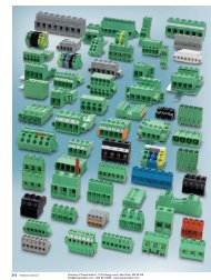
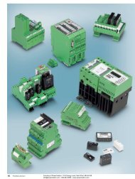
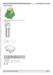
<strong>COMBICON</strong> <strong>control</strong><br />
<strong>PCB</strong> terminal blocks for MCR technology<br />
The diverse applications for <strong>PCB</strong><br />
terminal blocks in the area of MCR<br />
technology have resulted in a continually<br />
growing product line over the past several<br />
years. This line meets the requirements of<br />
a large number of different devices and the<br />
related device specifications.<br />
Regardless of whether modern process<br />
interfaces or auto<strong>mation</strong> components up<br />
to PLC’s are used, you will always find the<br />
connection terminal block for your<br />
application in the range of <strong>PCB</strong> terminal<br />
blocks.<br />
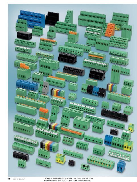
The <strong>PCB</strong> terminal block range provides<br />
three connection methods (screw, springcage<br />
and displacement connection). Singlelevel<br />
as well as double, three and four-level<br />
terminal blocks are available to increase<br />
the contact density on the <strong>PCB</strong>. The<br />
screw and spring-cage versions are pincompatible<br />
with each other. As a result,<br />
the user can choose between the two<br />
connection methods without changing the<br />
layout, in order to achieve a high level of<br />
flexibility in <strong>PCB</strong> production and reduce<br />
costs.<br />
The product line offers pitches from<br />
2.5 to 7.62 mm. The terminal blocks are<br />
designed for currents up to 41 A and<br />
voltages up to 400 V (surge voltage<br />
category III / pollution degree 3).<br />
Conductor cross sections from 0.08 to<br />
6mm 2 can be connected.<br />
When <strong>PCB</strong> terminal blocks are<br />
developed, the requirements of state-ofthe-art<br />
production methods for electronic<br />
modules, such as the through-hole reflow<br />
method or solderless assembly with pressin<br />
<strong>PCB</strong> terminal blocks are taken into<br />
account. The <strong>PCB</strong> terminal blocks,<br />
suitable for the reflow process are<br />
equipped with a high-temperature<br />
resistant insulation housing. The various<br />
series are also available in tubular or tape<br />
magazines.<br />
Customer-specific requirements can<br />
also be taken into account in the<br />
production of <strong>PCB</strong> terminal blocks. The<br />
terminal blocks are available with an<br />
enclosed clamping space, as partially<br />
assembled versions or in various colors.<br />
Please contact us.<br />
General 44<br />
<strong>PCB</strong> terminal blocks with screw connection for the 47<br />
reflow process, currents up to 24 A, 3.5 / 3.81 / 5.0 /<br />
5.08 mm pitch<br />
Connection cross section up to 1.5 mm 2<br />
47<br />
Connection cross section up to 2.5 mm 2<br />
49<br />
SMD <strong>PCB</strong> terminal blocks with connection cross section 50<br />
up to 1.5 mm 2<br />
<strong>PCB</strong> terminal blocks with screw connection for 51<br />
wave soldering processes, currents of up to 32 A,<br />
3.5 / 3.81 / 5.0 / 5.08 mm pitch<br />
Connection cross section up to 0.5 mm 2<br />
51<br />
Connection cross section up to 1.5 mm 2<br />
53<br />
Connection cross section up to 2.5 mm 2<br />
71<br />
Front connection up to 2.5 mm 2<br />
82<br />
Single terminal blocks up to 2.5 mm 2 85<br />
<strong>PCB</strong> terminal blocks with screw connection for wave 87<br />
soldering processes, currents of up to 41 A, pitch<br />
7.5 / 7.62 mm<br />
Connection cross section up to 1.5 mm 2<br />
87<br />
Connection cross section up to 2.5 mm 2<br />
91<br />
Single terminal blocks up to 4 mm 2 95<br />
<strong>PCB</strong> terminal blocks with spring-cage connection,<br />
currents up to 24 A, 3.81 / 5.0 / 5.08 mm pitch<br />
Connection cross section up to 1.5 mm 2<br />
97<br />
Connection cross section up to 2.5 mm 2 103<br />
<strong>PCB</strong> terminal blocks with push-in spring-cage 105<br />
connection for wave soldering processes, currents up<br />
to 24 A, 2.54 / 3.5 / 3.81 / 5.0 / 5.08 / 7.62 mm pitch<br />
Angled conductor connection up to 1.5 mm 2<br />
105<br />
Horizontal or vertical conductor connection up to 2.5 mm 2 109<br />
With actuation rocker with connection up to 1.5 mm 2 113<br />
<strong>PCB</strong> terminal blocks with displacement connection for<br />
wave soldering processes, currents up to 5 A, 3.81 mm pitch<br />
97<br />
121<br />
Connection cross section up to 0.34 mm 2 121<br />
<strong>PCB</strong> terminal blocks with screw connection for the<br />
Ex area for wave soldering processes<br />
123<br />
Multi-level terminal blocks with connection up to 1.5 mm 2 123<br />
Horizontal or vertical conductor connection up to 2.5 mm 2 124<br />
<strong>PCB</strong> terminal blocks with spring-cage connection for<br />
the Ex area for wave soldering processes<br />
127<br />
Angled conductor connection up to 2.5 mm 2<br />
127<br />
Horizontal or vertical conductor connection up to 2.5 mm 2 129<br />
<strong>PCB</strong> isolating connectors 130<br />
Flat-type fuse carriers 131<br />
Courtesy of <strong>Power</strong>/<strong>mation</strong>. 1310 Energy Lane, Saint Paul, MN 55108<br />
info@power<strong>mation</strong>.com - 800-843-9859 - www.power<strong>mation</strong>.com<br />
PHOENIX CONTACT<br />
43
<strong>COMBICON</strong> <strong>control</strong><br />
<strong>PCB</strong> terminal blocks for MCR technology<br />
Customer-specific standard terminal<br />
blocks<br />
Customer-specific requirements and<br />
requests can also be taken into account in<br />
the production of <strong>PCB</strong> terminal blocks. The<br />
terminal blocks are available with an<br />
enclosed clamping space, as partially<br />
assembled versions and in various colors.<br />
Standard terminal blocks with special<br />
functions<br />
The individual processing of <strong>PCB</strong><br />
terminal blocks in the soldering process,<br />
and even the particularities of a conductor<br />
connection are taken into account in many<br />
series. Here, you can choose between<br />
slotted-head and Phillips screws, and also<br />
between solder pins of different lengths.<br />
Please contact us.<br />
<strong>PCB</strong> terminal blocks with a variable<br />
number of positions<br />
<strong>PCB</strong> terminal blocks are available in<br />
three versions – as a one-piece block, as<br />
part blocks or as single terminal blocks. Part<br />
blocks can be assembled to form highposition<br />
blocks using a tongue and groove<br />
fitting. In the case of single terminal blocks,<br />
you can freely determine the number of<br />
positions for individual assembly. Only in<br />
cases of more than 30 positions should the<br />
row be interrupted to equalize possible<br />
tolerances between the terminal block and<br />
the <strong>PCB</strong>.<br />
<strong>PCB</strong> terminal blocks with open or enclosed<br />
clamping space<br />
Versions with slotted-head and Phillips<br />
screws<br />
One-piece blocks and <strong>PCB</strong> single terminal<br />
blocks<br />
Test connections<br />
In addition to the basic type, many <strong>PCB</strong><br />
terminal block series also offer pincompatible<br />
versions with test connections.<br />
Fully and partially assembled versions<br />
<strong>PCB</strong> terminal blocks with short or long solder<br />
pin<br />
Color variants<br />
<strong>PCB</strong> terminal blocks with integrated test<br />
connection<br />
44 PHOENIX CONTACT<br />
Courtesy of <strong>Power</strong>/<strong>mation</strong>. 1310 Energy Lane, Saint Paul, MN 55108<br />
info@power<strong>mation</strong>.com - 800-843-9859 - www.power<strong>mation</strong>.com
<strong>COMBICON</strong> <strong>control</strong><br />
<strong>PCB</strong> terminal blocks for MCR technology<br />
Polarization<br />
Especially 2 and 3-pos. terminal blocks<br />
are often exposed to high tightening<br />
torques that cannot be absorbed by a few<br />
solder pins. Normally, these terminal blocks<br />
must be supported for conductor<br />
connection. If this is not possible, variants<br />
with additional anti-rotation pins are<br />
available for many terminal blocks.<br />
Bridges<br />
Two methods are available to distribute<br />
potential or loop through a ground<br />
conductor in <strong>PCB</strong> terminal blocks. The<br />
easiest solution is a separate fixed bridge<br />
that is fixed in the connection area, if<br />
necessary with a feeding conductor. You<br />
can find internally bridged versions in the<br />
standard MKDS product range. The<br />
complete clamping space is also available in<br />
this case.<br />
Marking<br />
For labeling individual terminal points,<br />
marker cards (SK strips with consecutive<br />
numbers 1-10, 11-20) in the respective<br />
pitches of 2.5 to 7.62 mm can be supplied<br />
for both the single terminal blocks and the<br />
multi-position <strong>PCB</strong> termination blocks. As<br />
an alternative, the terminals can also be<br />
supplied with individual labeling.<br />
<strong>PCB</strong> terminal blocks with polarization pins<br />
Internal bridges<br />
Note:<br />
Since the installation environment of the<br />
entire printed circuit board cannot be<br />
influenced, the specified nominal voltage of<br />
all <strong>COMBICON</strong> <strong>PCB</strong> terminal blocks refers<br />
to the "as-delivered" condition. For more<br />
details as regards the dimensioning of air<br />
and creepage distances of printed circuit<br />
boards, see page 769.<br />
Separate fixed bridge<br />
Courtesy of <strong>Power</strong>/<strong>mation</strong>. 1310 Energy Lane, Saint Paul, MN 55108<br />
info@power<strong>mation</strong>.com - 800-843-9859 - www.power<strong>mation</strong>.com<br />
PHOENIX CONTACT<br />
45
<strong>COMBICON</strong> <strong>control</strong><br />
<strong>PCB</strong> terminal blocks with screw connection for the reflow process, currents of up to 24 A<br />
Connection cross-section of up to<br />
1.5 mm 2 Technical data MKDS 1/… HT BK MKDSN 1,5/… HT BK MKDS 1,5/… HT BK<br />
Note:<br />
In order to avoid tolerances between the terminal blocks and the<br />
<strong>PCB</strong>, the terminal row should be interrupted when the number of<br />
positions exceeds 30.<br />
1) Please observe the current carrying capacity curve. Further<br />
current carrying capacity curves on request.<br />
Metric 3.5 mm pitch<br />
Detection lug for models<br />
with a 3.81 mm inch pitch<br />
– Application in SMT reflow processes<br />
– Standard types of <strong>PCB</strong> terminal blocks<br />
made of high-temperature resistant<br />
plastics<br />
– Delivery form: box packaging - bulk<br />
– Taped packaging in accordance with<br />
IEC 60286-3 for automatic assembly on<br />
request<br />
– You can find user notes and<br />
recommendations for the<br />
THR procedure on page 27<br />
Accessories<br />
For all types Type Page<br />
Only for MKDS 1/... HT BK<br />
Screwdriver<br />
SZS 0,4 x 2,5<br />
Order No.<br />
1205037<br />
Marker cards<br />
SK 3,5/2,8 or SK<br />
3,81/2,8<br />
487<br />
Only for MKDSN 1,5/...-HT BK and MKDS 1,5/...HT BK<br />
Screwdriver<br />
SZS 0,6 x 3,5<br />
Order No.<br />
1205053<br />
Insertion bridge<br />
EBP...- 5<br />
498<br />
Current carrying capacity curve<br />
Type: MKDS 1,5/...-HT BK<br />
Test as per DIN EN 60512-5-2:2003-01<br />
Reduction factor = 1<br />
No. of positions = 5<br />
Current carrying capacity [A]<br />
54<br />
48<br />
42<br />
36<br />
30<br />
24<br />
1<br />
18<br />
12<br />
6 1 = 2,5mm 2<br />
0<br />
0 20 40 60 80<br />
100<br />
Ambient temperature [°C]<br />
Marker cards<br />
SK 5/3,8 or SK 5,08/3,8<br />
488<br />
Technical data in accordance with IEC / DIN VDE<br />
Rated current / conductor cross-section [A] / [mm²] 10 1 ) / 1 13.5 1 ) / 1.5 17.5 1 ) / 1.5<br />
Rated insulation voltage with pollution degree 2 [V] 200 320 320<br />
Pitch [mm] 3.5 / 3.81 5 / 5.08 5 / 5.08<br />
Connection capacity<br />
Solid / stranded [mm²] / [mm²] / AWG 0.14 - 1.5 / 0.14 - 1 / 26 - 16 0.14 - 1.5 / 0.14 - 1.5 / 26 - 16 0.14 - 2.5 / 0.14 - 1.5 / 26 - 14<br />
Stranded with ferrules without plastic sleeve [mm 2 ] 0.25 - 0.25 0.25 - 1 0.25 - 1.5<br />
Stranded with ferrules with plastic sleeve [mm 2 ] 0.25 - 0.5 0.25 - 1.5 0.25 - 1.5<br />
Multi-conductor connection capacity (2 cond. with the same cross section)<br />
Solid / stranded [mm 2 ] 0.14 - 0.5 / 0.14 - 0.2 0.14 - 0.75 / 0.14 - 0.75 0.14 - 1 / 0.14 - 0.75<br />
Insulation coordination<br />
Surge voltage category / pollution degree III / 3 III / 2 II / 2 III / 3 III / 2 II / 2 III / 3 III / 2 II / 2<br />
Rated insulation voltage [V] 63 200 200 200 320 320 200 320 320<br />
Rated surge voltage [kV] 2.5 2.5 2.5 4 4 4 4 4 4<br />
Approval data (UL/CUL) Use Group B C D B C D B C D<br />
Nominal voltage [V] 300 - 300 300 - 300 300 - 300<br />
Nominal current [A] 10 - 10 10 - 10 15 - 10<br />
Connection capacity AWG AWG 30 - 16 - 30 - 16 30 - 14 - 30 - 14 30 - 14 - 30 - 14<br />
Approval data (CSA) Use Group B C D B C D B C D<br />
Nominal voltage [V] 150 - 300 - - - - - -<br />
Nominal current [A] 10 - 10 - - - - - -<br />
Connection capacity AWG AWG 28 - 16 - 28 - 16 - - - - - -<br />
General data<br />
Stripping length [mm] 5 6 7<br />
Screw thread M2 M3 M3<br />
Tightening torque [Nm] 0.22 - 0.25 0.5 - 0.6 0.5 - 0.6<br />
Type of insulation material / group of insulation material PA / IIIa PA / IIIa PA / IIIa<br />
Inflammability class acc. to UL 94 V0 V0 V0<br />
Bore hole diameter/ pin dimensions [mm] 1.1 / 0.5 x 0.9 mm 1.3 / 0.5 x 1 mm 1.3 / 0.9 x 0.9 mm<br />
No. of pos. Dim. a<br />
[mm]<br />
2 3.50<br />
3 7.00<br />
2 3.81<br />
3 7.62<br />
2 5.00<br />
3 10.00<br />
2 5.08<br />
3 10.16<br />
46 PHOENIX CONTACT<br />
Courtesy of <strong>Power</strong>/<strong>mation</strong>. 1310 Energy Lane, Saint Paul, MN 55108<br />
info@power<strong>mation</strong>.com - 800-843-9859 - www.power<strong>mation</strong>.com
<strong>COMBICON</strong> <strong>control</strong><br />
<strong>PCB</strong> terminal blocks with screw connection for the reflow process, currents of up to 24 A<br />
MKDS 1/… HT BK<br />
<strong>PCB</strong> terminal block with screw connection,<br />
without housing overlapping<br />
MKDSN 1,5/… HT BK<br />
<strong>PCB</strong> terminal block with screw connection, low design,<br />
with housing overlapping<br />
MKDS 1,5/… HT BK<br />
<strong>PCB</strong> terminal block with screw connection,<br />
with housing overlapping<br />
u C s P CCA j us CCA j us P CCA j<br />
7,3<br />
Dimensional drawing Dimensional drawing Dimensional drawing<br />
a+4<br />
(a+3,8)<br />
8,1<br />
a+5<br />
(a+5,08)<br />
9,8<br />
a+5<br />
(a+5,08)<br />
3,5 8,5<br />
3,5<br />
10<br />
3,5<br />
13,8<br />
3,6<br />
2<br />
(1,9)<br />
3,5<br />
(3,81)<br />
a<br />
3,5<br />
(3,81)<br />
a 2<br />
(1,9)<br />
5<br />
(5,08)<br />
a<br />
2,5<br />
(2,54)<br />
5<br />
(5,08)<br />
a<br />
2,5<br />
(2,54)<br />
3,6<br />
4,05<br />
2,5 5<br />
(2,54) (5,08)<br />
a<br />
4,6<br />
2,5 5<br />
(2,54) (5,08)<br />
Drilling diagram Drilling diagram Drilling diagram<br />
a<br />
4,6<br />
4,05<br />
1,1<br />
1,3<br />
1,3<br />
Ordering data Ordering data Ordering data<br />
Type Order No. Pcs. / Pkt. Type Order No. Pcs. / Pkt. Type Order No. Pcs. / Pkt.<br />
Pitch 3.5 mm, color: black<br />
MKDS 1/ 2-3,5 HT BK 1985807 50<br />
MKDS 1/ 3-3,5 HT BK 1984950 50<br />
Pitch 3.81 mm, color: black<br />
MKDS 1/ 2-3,81 HT BK 1985823 50<br />
MKDS 1/ 3-3,81 HT BK 1985836 50<br />
5.0 mm pitch, color: black 5.0 mm pitch, color: black<br />
MKDSN 1,5/ 2 HT BK 1985849 50 MKDS 1,5/ 2 HT BK 1985881 50<br />
MKDSN 1,5/ 3 HT BK 1985852 50 MKDS 1,5/ 3 HT BK 1985894 50<br />
5.08 mm pitch, color: black 5.08 mm pitch, color: black<br />
MKDSN 1,5/ 2-5,08 HT BK 1985865 50 MKDS 1,5/ 2-5,08 HT BK 1985904 50<br />
MKDSN 1,5/ 3-5,08 HT BK 1985878 50 MKDS 1,5/ 3-5,08 HT BK 1985917 50<br />
Courtesy of <strong>Power</strong>/<strong>mation</strong>. 1310 Energy Lane, Saint Paul, MN 55108<br />
info@power<strong>mation</strong>.com - 800-843-9859 - www.power<strong>mation</strong>.com<br />
PHOENIX CONTACT<br />
47
<strong>COMBICON</strong> <strong>control</strong><br />
<strong>PCB</strong> terminal blocks with screw connection for the reflow process, currents of up to 24 A<br />
Connection cross-section of up to<br />
2.5 mm 2 Technical data MKDSN 2,5/… HT BK MKDS 3/… HT BK<br />
Note:<br />
In order to avoid tolerances between the terminal blocks and the<br />
<strong>PCB</strong>, the terminal row should be interrupted when the number of<br />
positions exceeds 30.<br />
1) Please observe the current carrying capacity curve. Further<br />
current carrying capacity curves on request.<br />
Metric 5 mm pitch<br />
Detection lug for<br />
models with a 5.08 mm inch pitch<br />
– Application in SMT reflow processes<br />
– Standard types of <strong>PCB</strong> terminal blocks<br />
made of high-temperature resistant<br />
plastics<br />
– Delivery form: box packaging - bulk<br />
– Taped packaging in accordance with<br />
IEC 60286-3 for automatic assembly on<br />
request<br />
– You can find user notes and<br />
recommendations for the<br />
THR procedure on page 27<br />
Accessories<br />
For all types Type Page<br />
Screwdriver<br />
SZS 0,6 x 3,5<br />
Order No.<br />
1205053<br />
Marker cards<br />
SK 5/3,8 or SK 5,08/3,8<br />
Insertion bridge<br />
EBP...- 5<br />
488<br />
498<br />
Current carrying capacity curve<br />
Type: MKDS 3/...HT BK<br />
Test following DIN EN 60512-5-2:2003-01<br />
Reduction factor = 1<br />
No. of positions = 5<br />
Current carrying capacity [A]<br />
60<br />
54<br />
48<br />
42<br />
36<br />
30<br />
1<br />
24<br />
18<br />
12<br />
6 1 = 4mm 2<br />
0<br />
0 20 40 60 80<br />
100<br />
Ambient temperature [°C]<br />
Technical data in accordance with IEC / DIN VDE<br />
Rated current / conductor cross-section [A] / [mm²] 16 1 ) / 2.5 24 1 ) / 2.5<br />
Rated insulation voltage with pollution degree 2 [V] 320 320<br />
Pitch [mm] 5 / 5.08 5 / 5.08<br />
Connection capacity<br />
Solid / stranded [mm²] / [mm²] / AWG 0.2 - 2.5 / 0.2 - 2.5 / 24 - 14 0.2 - 4 / 0.2 - 2.5 / 24 - 12<br />
Stranded with ferrules without plastic sleeve [mm 2 ] 0.25 - 2.5 0.25 - 2.5<br />
Stranded with ferrules with plastic sleeve [mm 2 ] 0.25 - 2.5 0.25 - 1.5<br />
Multi-conductor connection capacity (2 cond. with the same cross section)<br />
Solid / stranded [mm 2 ] 0.2 - 0.75 / 0.2 - 0.75 0.2 - 1.5 / 0.2 - 1.5<br />
Stranded with ferrules without plastic sleeve [mm 2 ] 0.25 - 0.75 0.25 - 0.75<br />
Stranded with TWIN ferrules with plastic sleeve [mm 2 ] 0.5 - 1.5 0.5 - 1.5<br />
Insulation coordination<br />
Surge voltage category / pollution degree III / 3 III / 2 II / 2 III / 3 III / 2 II / 2<br />
Rated insulation voltage [V] 200 320 320 200 320 320<br />
Rated surge voltage [kV] 4 4 4 4 4 4<br />
Approval data (UL/CUL) Use Group B C D B C D<br />
Nominal voltage [V] 300 - 300 300 - 300<br />
Nominal current [A] 10 - 10 15 - 10<br />
Connection capacity AWG AWG 30 - 12 - 30 - 12 30 - 12 - 30 - 12<br />
Approval data (CSA) Use Group B C D B C D<br />
Nominal voltage [V] - - - 300 - 300<br />
Nominal current [A] - - - 10 - 10<br />
Connection capacity AWG AWG - - - 28 - 12 - 28 - 12<br />
General data<br />
Stripping length [mm] 6.5 8<br />
Screw thread M3 M3<br />
Tightening torque [Nm] 0.5 - 0.6 0.5 - 0.6<br />
Type of insulation material / group of insulation material PA / IIIa PA / IIIa<br />
Inflammability class acc. to UL 94 V0 V0<br />
Bore hole diameter/ pin dimensions [mm] 1.3 / 0.8 x 0.9 mm 1.3 / 0.9 x 0.9 mm<br />
No. of pos. Dim. a<br />
[mm]<br />
2 5.00<br />
3 10.00<br />
2 5.08<br />
3 10.16<br />
48 PHOENIX CONTACT<br />
Courtesy of <strong>Power</strong>/<strong>mation</strong>. 1310 Energy Lane, Saint Paul, MN 55108<br />
info@power<strong>mation</strong>.com - 800-843-9859 - www.power<strong>mation</strong>.com
<strong>COMBICON</strong> <strong>control</strong><br />
<strong>PCB</strong> terminal blocks with screw connection for the reflow process, currents of up to 24 A<br />
MKDSN 2,5/… HT BK<br />
<strong>PCB</strong> terminal block with screw connection, low design,<br />
with housing overlapping<br />
MKDS 3/… HT BK<br />
<strong>PCB</strong> terminal block with screw connection,<br />
with housing overlapping<br />
u s P CCA j<br />
Dimensional drawing<br />
9,5<br />
a+5<br />
(a+5,08)<br />
uC s CCA j<br />
Dimensional drawing<br />
11,2<br />
a+5<br />
(a+5,08)<br />
15<br />
18<br />
3,5<br />
5<br />
4,75<br />
2,5 5<br />
(2,54) (5,08)<br />
a<br />
5,5<br />
5<br />
(5,08)<br />
a<br />
2,5<br />
(2,54) 5<br />
(5,08)<br />
a<br />
2,5<br />
(2,54)<br />
4,75<br />
2,5 5<br />
(2,54) (5,08)<br />
a<br />
Drilling diagram<br />
Drilling diagram<br />
5,5<br />
1,3<br />
1,3<br />
Ordering data<br />
Ordering data<br />
Type Order No. Pcs. / Pkt. Type Order No. Pcs. / Pkt.<br />
5.0 mm pitch, color: black 5.0 mm pitch, color: black<br />
MKDSN 2,5/ 2 HT BK 1985920 50 MKDS 3/ 2 HT BK 1985962 50<br />
MKDSN 2,5/ 3 HT BK 1985933 50 MKDS 3/ 3 HT BK 1985975 50<br />
5.08 mm pitch, color: black 5.08 mm pitch, color: black<br />
MKDSN 2,5/ 2-5,08 HT BK 1985946 50 MKDS 3/ 2-5,08 HT BK 1985988 50<br />
MKDSN 2,5/ 3-5,08 HT BK 1985959 50 MKDS 3/ 3-5,08 HT BK 1985991 50<br />
Courtesy of <strong>Power</strong>/<strong>mation</strong>. 1310 Energy Lane, Saint Paul, MN 55108<br />
info@power<strong>mation</strong>.com - 800-843-9859 - www.power<strong>mation</strong>.com<br />
PHOENIX CONTACT<br />
49
<strong>COMBICON</strong> <strong>control</strong><br />
<strong>PCB</strong> terminal blocks with screw connection for the reflow process, currents of up to 24 A<br />
SMD terminal blocks with a connection<br />
cross-section of up to 1.5 mm 2<br />
Note:<br />
Mounting screw B 2,2 x 6,5, ISO 7049/DIN ISO 7049 is supplied as<br />
standard. Insertion hole: 2.6 mm, soldering tag: 2.5 x 1.2 mm<br />
Note:<br />
When ordering, please note the size of packaging. For production<br />
reasons, only complete tube magazines can be delivered.<br />
1) Current carrying capacity curve upon request.<br />
MKDS 1/...-3,81-SMD BK<br />
<strong>PCB</strong> terminal block with screw connection,<br />
for SMD connection method,<br />
without housing overlapping, delivery: magazined packing<br />
– Application in SMT reflow processes<br />
– Standard types of <strong>PCB</strong> terminal blocks<br />
made of high-temperature resistant<br />
plastics<br />
– Type of packing: tube magazine<br />
– Box packaging or tape-on-reel packing in<br />
accordance with IEC 60286-3 for<br />
automatic assembly on request<br />
– You can find user notes and<br />
recommendations for the<br />
THR procedure on page 27<br />
Accessories<br />
For all types Type Page<br />
Screwdriver<br />
SZS 0,4 x 2,5<br />
Order No.<br />
1205037<br />
Marker card<br />
SK 3,81/2,8<br />
487<br />
u C<br />
9,2<br />
3,5<br />
7,3 2<br />
Dimensional drawing<br />
a<br />
3,81 3,81<br />
a+11,43<br />
1,9 3,81 a<br />
Drilling diagram<br />
3,85 2,5<br />
1,5<br />
2,6<br />
Technical data<br />
Technical data in accordance with IEC / DIN VDE<br />
Rated current / conductor cross-section [A] / [mm²] 8 1 ) / 1<br />
Rated insulation voltage with pollution degree 2 [V] 160<br />
Pitch [mm] 3.81<br />
Connection capacity<br />
Solid / stranded [mm²] / [mm²] / AWG 0.14 - 1.5 / 0.14 - 1 / 26 - 16<br />
Stranded with ferrules without plastic sleeve [mm 2 ] 0.25 - 0.5<br />
Stranded with ferrules with plastic sleeve [mm 2 ] 0.25 - 0.5<br />
Multi-conductor connection capacity (2 cond. with the same cross section)<br />
Solid / stranded [mm 2 ] 0.14 - 0.5 / 0.14 - 0.2<br />
Stranded with ferrules without plastic sleeve [mm 2 ] -<br />
Stranded with TWIN ferrules with plastic sleeve [mm 2 ] -<br />
Insulation coordination<br />
Surge voltage category / pollution degree III / 3 III / 2 II / 2<br />
Rated insulation voltage [V] 160 160 250<br />
Rated surge voltage [kV] 2.5 2.5 2.5<br />
Approval data (UL/CUL) Use Group B C D<br />
Nominal voltage [V] 300 - 300<br />
Nominal current [A] 10 - 10<br />
Connection capacity AWG AWG 30 - 16 - 30 - 16<br />
Approval data (CSA) Use Group B C D<br />
Nominal voltage [V] 150 - 300<br />
Nominal current [A] 10 - 10<br />
Connection capacity AWG AWG 28 - 16 - 28 - 16<br />
General data<br />
Stripping length [mm] 5<br />
Screw thread<br />
M2<br />
Tightening torque [Nm] 0.22 - 0.25<br />
Type of insulation material / group of insulation material<br />
PA-F / IIIa<br />
Inflammability class acc. to UL 94<br />
V0<br />
Ordering data<br />
Type Order No. Pcs. / Pkt.<br />
No. of pos. Dim. a Pitch 3.81 mm, color: black<br />
[mm]<br />
2 3.81 MKDS 1/ 2-3,81 SMD BK 1727230 35<br />
3 7.62 MKDS 1/ 3-3,81 SMD BK 1727243 28<br />
4 11.43 MKDS 1/ 4-3,81 SMD BK 1727256 23<br />
5 15.24 MKDS 1/ 5-3,81 SMD BK 1727269 20<br />
6 19.05 MKDS 1/ 6-3,81 SMD BK 1727272 17<br />
7 22.86 MKDS 1/ 7-3,81 SMD BK 1727285 15<br />
8 26.67 MKDS 1/ 8-3,81 SMD BK 1727175 14<br />
9 30.48 MKDS 1/ 9-3,81 SMD BK 1727298 12<br />
10 34.29 MKDS 1/10-3,81 SMD BK 1727308 11<br />
11 38.10 MKDS 1/11-3,81 SMD BK 1727311 10<br />
12 41.91 MKDS 1/12-3,81 SMD BK 1727324 10<br />
50 PHOENIX CONTACT<br />
Courtesy of <strong>Power</strong>/<strong>mation</strong>. 1310 Energy Lane, Saint Paul, MN 55108<br />
info@power<strong>mation</strong>.com - 800-843-9859 - www.power<strong>mation</strong>.com
Connection cross-section of up to<br />
<strong>COMBICON</strong> <strong>control</strong><br />
<strong>PCB</strong> terminal blocks with screw connection for wave soldering processes, currents of up to 32 A<br />
0.5 mm 2 Technical data<br />
Note:<br />
The 2 and 3-position variants have a locating pin (1.5 mm long) to<br />
support the mechanical load.<br />
Drilling diagram and dimensional drawing MPT 0,5/...2,54, for no. of<br />
pos. 2 to 3, see page 515.<br />
MPT 0,5/...-2,54<br />
MICRO <strong>PCB</strong> terminal block with screw connection with an IC pitch<br />
Accessories<br />
For all types Type Page<br />
Marker cards<br />
486<br />
SK 2,54/2,8<br />
u C<br />
Dimensional drawing<br />
6,2<br />
a+3<br />
– MICRO <strong>PCB</strong> terminal block with an<br />
IC pitch of 2.54 mm<br />
– Single-row type with horizontal<br />
connection direction<br />
– Application in miniature assemblies with<br />
high contact density<br />
Screwdriver<br />
SZS 0,4 X 2,0<br />
Order No.<br />
1205202<br />
3,5 8,5<br />
3,1<br />
1,5<br />
2,54<br />
a<br />
Drilling diagram<br />
4 to 12-pos. variants<br />
1,5<br />
a<br />
2,54<br />
3,1<br />
1,1<br />
Technical data in accordance with IEC / DIN VDE<br />
Rated current / conductor cross-section [A] / [mm²] 6 / 0.5<br />
Rated insulation voltage with pollution degree 2 [V] 160<br />
Pitch [mm] 2.54<br />
Connection capacity<br />
Solid / stranded [mm²] / [mm²] / AWG 0.14 - 0.5 / 0.14 - 0.5 / 26 - 20<br />
Stranded with ferrules without plastic sleeve [mm 2 ] 0.25 - 0.34<br />
Stranded with ferrules with plastic sleeve [mm 2 ] 0.25 - 0.34<br />
Multi-conductor connection capacity (2 cond. with the same cross section)<br />
Solid / stranded [mm 2 ] 0.14 - 0.34 / 0.14 - 0.34<br />
Stranded with ferrules without plastic sleeve [mm 2 ] -<br />
Stranded with TWIN ferrules with plastic sleeve [mm 2 ] -<br />
Insulation coordination<br />
Surge voltage category / pollution degree III / 3 III / 2 II / 2<br />
Rated insulation voltage [V] 63 160 320<br />
Rated surge voltage [kV] 1.5 1.5 2.5<br />
Approval data (UL/CUL) Use Group B C D<br />
Nominal voltage [V] 125 - -<br />
Nominal current [A] 6 - -<br />
Connection capacity AWG AWG 30 - 20 - -<br />
Approval data (CSA) Use Group B C D<br />
Nominal voltage [V] 125 - -<br />
Nominal current [A] 6 - -<br />
Connection capacity AWG AWG 28 - 20 - -<br />
General data<br />
Stripping length [mm] 4.5<br />
Screw thread M1,6<br />
Tightening torque [Nm] 0.12 - 0.15<br />
Type of insulation material / group of insulation material<br />
PA / I<br />
Inflammability class acc. to UL 94<br />
V0<br />
Bore hole diameter/ pin dimensions [mm] 1.1 / 0.5 x 0.9 mm<br />
Ordering data<br />
Type Order No. Pcs. / Pkt.<br />
No. of pos. Dim. a 2.54 mm pitch, color: green<br />
[mm]<br />
2 2.54 MPT 0,5/ 2-2,54 1725656 50<br />
3 5.08 MPT 0,5/ 3-2,54 1725669 50<br />
4 7.62 MPT 0,5/ 4-2,54 1725672 50<br />
5 10.16 MPT 0,5/ 5-2,54 1725685 50<br />
6 12.70 MPT 0,5/ 6-2,54 1725698 50<br />
7 15.24 MPT 0,5/ 7-2,54 1725708 50<br />
8 17.78 MPT 0,5/ 8-2,54 1725711 50<br />
9 20.32 MPT 0,5/ 9-2,54 1725724 50<br />
10 22.86 MPT 0,5/10-2,54 1725737 50<br />
11 25.40 MPT 0,5/11-2,54 1725740 50<br />
12 27.94 MPT 0,5/12-2,54 1725753 50<br />
Courtesy of <strong>Power</strong>/<strong>mation</strong>. 1310 Energy Lane, Saint Paul, MN 55108<br />
info@power<strong>mation</strong>.com - 800-843-9859 - www.power<strong>mation</strong>.com<br />
PHOENIX CONTACT<br />
51
<strong>COMBICON</strong> <strong>control</strong><br />
<strong>PCB</strong> terminal blocks with screw connection for wave soldering processes, currents of up to 32 A<br />
Connection cross-section of up to<br />
1.5 mm 2 Technical data MKDS 1 SMKDS 1 MKKDS 1<br />
Note:<br />
In order to avoid tolerances between the terminal blocks and the<br />
<strong>PCB</strong>, the terminal row should be interrupted when the number of<br />
positions exceeds 30.<br />
1) Please observe the current carrying capacity curve. Further<br />
current carrying capacity curves on request.<br />
Metric 3.5 mm pitch<br />
Detection lug for models<br />
with a 3.81 mm inch pitch<br />
– <strong>PCB</strong> terminal blocks with extremely<br />
compact housing dimensions<br />
MKDS 1/...<br />
– Single-row type with horizontal<br />
connection direction<br />
SMKDS 1/…<br />
– The conductor and screwdriver axis at<br />
an angle of 55° to the usual direction<br />
– An arrangement of several terminal<br />
block rows one behind the other –<br />
multi-level effect with the same low<br />
design<br />
MKKDS 1/…<br />
– Double-level type with high packaging<br />
and connection density<br />
– Offset levels for optimum accessibility<br />
of the terminal points<br />
Accessories<br />
For all types Type Page<br />
Marker cards<br />
SK 3,5/2,8 or SK<br />
3,81/2,8<br />
487<br />
Screwdriver<br />
SZS 0,4 x 2,5<br />
Order No.<br />
1205037<br />
Current carrying capacity curve<br />
Type: MKDS 1/5-3,5<br />
Test following DIN EN 60512-5-2:2003-01<br />
Reduction factor = 1<br />
No. of positions = 5<br />
Current carrying capacity [A]<br />
12<br />
10<br />
8<br />
6<br />
4<br />
2<br />
0<br />
0<br />
20<br />
40<br />
1,5 mm 2<br />
60 80 100<br />
Ambient temperature [°C]<br />
Technical data in accordance with IEC / DIN VDE<br />
Rated current / conductor cross-section [A] / [mm²] 10 1 ) / 1 10 1 ) / 1 8 1 ) / 1<br />
Rated insulation voltage with pollution degree 2 [V] 200 200 200<br />
Pitch [mm] 3.5 / 3.81 3.5 / 3.81 3.5 / 3.81<br />
Connection capacity<br />
Solid / stranded [mm²] / [mm²] / AWG 0.14 - 1.5 / 0.14 - 1 / 26 - 16 0.14 - 1.5 / 0.14 - 1 / 26 - 16 0.14 - 1.5 / 0.14 - 1 / 26 - 16<br />
Stranded with ferrules without plastic sleeve [mm 2 ] 0.25 - 0.5 0.25 - 0.5 0.25 - 0.5<br />
Stranded with ferrules with plastic sleeve [mm 2 ] 0.25 - 0.5 0.25 - 0.5 0.25 - 0.5<br />
Multi-conductor connection capacity (2 cond. with the same cross section)<br />
Solid / stranded [mm 2 ] 0.14 - 0.5 / 0.14 - 0.2 0.14 - 0.5 / 0.14 - 0.2 0.14 - 0.5 / 0.14 - 0.2<br />
Insulation coordination<br />
Surge voltage category / pollution degree III / 3 III / 2 II / 2 III / 3 III / 2 II / 2 III / 3 III / 2 II / 2<br />
Rated insulation voltage [V] 160 200 400 160 200 400 160 200 400<br />
Rated surge voltage [kV] 2.5 2.5 2.5 2.5 2.5 2.5 2.5 2.5 2.5<br />
Approval data (UL/CUL) Use Group B C D B C D B C D<br />
Nominal voltage [V] 300 - 300 300 - 300 300 - 300<br />
Nominal current [A] 10 - 10 10 - 10 10 - 10<br />
Connection capacity AWG AWG 30 - 16 - 30 - 16 30 - 16 - 30 - 16 30 - 16 - 30 - 16<br />
Approval data (CSA) Use Group B C D B C D B C D<br />
Nominal voltage [V] 150 - 300 150 - 300 150 - 300<br />
Nominal current [A] 10 - 10 10 - 10 10 - 10<br />
Connection capacity AWG AWG 28 - 16 - 28 - 16 28 - 16 - 28 - 16 28 - 16 - 28 - 16<br />
General data<br />
Stripping length [mm] 5 5 5<br />
Screw thread M2 M2 M2<br />
Tightening torque [Nm] 0.22 - 0.25 0.22 - 0.25 0.22 - 0.25<br />
Type of insulation material / group of insulation material PA / I PA / I PA / I<br />
Inflammability class acc. to UL 94 V0 V0 V0<br />
Bore hole diameter/ pin dimensions [mm] 1.1 / 0.5 x 0.9 mm 1.1 / 0.5 x 0.9 mm 1.1 / 0.5 x 0.9 mm<br />
No. of pos. Dim. a<br />
[mm]<br />
2 3.50<br />
3 7.00<br />
4 10.50<br />
5 14.00<br />
6 17.50<br />
7 21.00<br />
8 24.50<br />
9 28.00<br />
10 31.50<br />
11 35.00<br />
12 38.50<br />
13 42.00<br />
14 45.50<br />
15 49.00<br />
16 52.50<br />
2 3.81<br />
3 7.62<br />
4 11.43<br />
5 15.24<br />
6 19.05<br />
7 22.86<br />
8 26.67<br />
9 30.48<br />
10 34.29<br />
11 38.10<br />
12 41.91<br />
52 PHOENIX CONTACT<br />
Courtesy of <strong>Power</strong>/<strong>mation</strong>. 1310 Energy Lane, Saint Paul, MN 55108<br />
info@power<strong>mation</strong>.com - 800-843-9859 - www.power<strong>mation</strong>.com
<strong>COMBICON</strong> <strong>control</strong><br />
<strong>PCB</strong> terminal blocks with screw connection for wave soldering processes, currents of up to 32 A<br />
MKDS 1<br />
<strong>PCB</strong> terminal block with screw connection,<br />
without housing overlapping<br />
SMKDS 1<br />
<strong>PCB</strong> terminal block with screw connection,<br />
with 55° angled connection direction,<br />
without housing overlapping<br />
MKKDS 1<br />
Double-level <strong>PCB</strong> terminal block with offset levels,<br />
without housing overlapping<br />
u C s P CCA j uC s P CCA j uC s P CCA j<br />
Dimensional drawing Dimensional drawing Dimensional drawing<br />
7,3<br />
a+4<br />
(a+3,8)<br />
10<br />
a+4<br />
(a+3,8)<br />
16,3<br />
a+4<br />
(a+3,81)<br />
1,75<br />
(1,9)<br />
3,5 8,5<br />
3,6<br />
3,5<br />
(3,81)<br />
a<br />
2<br />
(1,9)<br />
2<br />
(1,9)<br />
a<br />
3,5<br />
(3,81)<br />
2<br />
(1,9)<br />
a<br />
3,5<br />
(3,81)<br />
1,75<br />
(1,9)<br />
3,6<br />
4,3<br />
11,4<br />
9,5<br />
16,2<br />
8,5<br />
2<br />
(1,9)<br />
3,5<br />
(3,81)<br />
a<br />
3,5<br />
4,3<br />
2<br />
(1,9)<br />
3,5<br />
(3,81)<br />
a<br />
3,5<br />
3,6<br />
11,4<br />
2<br />
(1,9)<br />
3,5<br />
(3,81)<br />
a<br />
1,75<br />
(1,9)<br />
Drilling diagram Drilling diagram Drilling diagram<br />
1,1<br />
1,1<br />
3,6<br />
1,1<br />
Ordering data Ordering data Ordering data<br />
Type Order No. Pcs. / Pkt. Type Order No. Pcs. / Pkt. Type Order No. Pcs. / Pkt.<br />
Pitch 3.5 mm, color: green Pitch 3.5 mm, color: green Pitch 3.5 mm, color: green<br />
MKDS 1/ 2-3,5 1751248 50 SMKDS 1/ 2-3,5 1751099 50 MKKDS 1/ 2-3,5 1751390 50<br />
MKDS 1/ 3-3,5 1751251 50 SMKDS 1/ 3-3,5 1751109 50 MKKDS 1/ 3-3,5 1751400 50<br />
MKDS 1/ 4-3,5 1751264 50 SMKDS 1/ 4-3,5 1751112 50 MKKDS 1/ 4-3,5 1751413 50<br />
MKDS 1/ 5-3,5 1751277 50 SMKDS 1/ 5-3,5 1751125 50 MKKDS 1/ 5-3,5 1751426 50<br />
MKDS 1/ 6-3,5 1751280 50 SMKDS 1/ 6-3,5 1751138 50 MKKDS 1/ 6-3,5 1751439 50<br />
MKDS 1/ 7-3,5 1751293 50 SMKDS 1/ 7-3,5 1751141 50 MKKDS 1/ 7-3,5 1751442 50<br />
MKDS 1/ 8-3,5 1751303 50 SMKDS 1/ 8-3,5 1751154 50 MKKDS 1/ 8-3,5 1751455 50<br />
MKDS 1/ 9-3,5 1751316 50 SMKDS 1/ 9-3,5 1751167 50 MKKDS 1/ 9-3,5 1751468 50<br />
MKDS 1/10-3,5 1751329 50 SMKDS 1/10-3,5 1751170 50 MKKDS 1/10-3,5 1751471 50<br />
MKDS 1/11-3,5 1751332 50 SMKDS 1/11-3,5 1751183 50 MKKDS 1/11-3,5 1751484 50<br />
MKDS 1/12-3,5 1751345 50 SMKDS 1/12-3,5 1751196 50 MKKDS 1/12-3,5 1751497 50<br />
MKDS 1/13-3,5 1751358 50 SMKDS 1/13-3,5 1751206 50 MKKDS 1/13-3,5 1751507 50<br />
MKDS 1/14-3,5 1751361 50 SMKDS 1/14-3,5 1751219 50 MKKDS 1/14-3,5 1751510 50<br />
MKDS 1/15-3,5 1751374 50 SMKDS 1/15-3,5 1751222 50 MKKDS 1/15-3,5 1751523 50<br />
MKDS 1/16-3,5 1751387 50 SMKDS 1/16-3,5 1751235 50 MKKDS 1/16-3,5 1751536 50<br />
Pitch 3.81 mm, color: green Pitch 3.81 mm, color: green Pitch 3.81 mm, color: green<br />
MKDS 1/ 2-3,81 1727010 50 SMKDS 1/ 2-3,81 1728284 50 MKKDS 1/ 2-3,81 1708026 50<br />
MKDS 1/ 3-3,81 1727023 50 SMKDS 1/ 3-3,81 1728297 50 MKKDS 1/ 3-3,81 1708039 50<br />
MKDS 1/ 4-3,81 1727036 50 SMKDS 1/ 4-3,81 1728307 50 MKKDS 1/ 4-3,81 1708042 50<br />
MKDS 1/ 5-3,81 1727049 50 SMKDS 1/ 5-3,81 1728310 50 MKKDS 1/ 5-3,81 1708055 50<br />
MKDS 1/ 6-3,81 1727052 50 SMKDS 1/ 6-3,81 1728323 50 MKKDS 1/ 6-3,81 1708068 50<br />
MKDS 1/ 7-3,81 1727065 50 SMKDS 1/ 7-3,81 1728336 50 MKKDS 1/ 7-3,81 1708071 50<br />
MKDS 1/ 8-3,81 1727078 50 SMKDS 1/ 8-3,81 1728349 50 MKKDS 1/ 8-3,81 1708084 50<br />
MKDS 1/ 9-3,81 1727081 50 SMKDS 1/ 9-3,81 1728352 50 MKKDS 1/ 9-3,81 1708107 50<br />
MKDS 1/10-3,81 1727094 50 SMKDS 1/10-3,81 1728365 50 MKKDS 1/10-3,81 1708110 50<br />
MKDS 1/11-3,81 1727104 50 SMKDS 1/11-3,81 1728378 50 MKKDS 1/11-3,81 1708123 50<br />
MKDS 1/12-3,81 1727117 50 SMKDS 1/12-3,81 1728381 50 MKKDS 1/12-3,81 1708136 50<br />
Courtesy of <strong>Power</strong>/<strong>mation</strong>. 1310 Energy Lane, Saint Paul, MN 55108<br />
info@power<strong>mation</strong>.com - 800-843-9859 - www.power<strong>mation</strong>.com<br />
PHOENIX CONTACT<br />
53
<strong>COMBICON</strong> <strong>control</strong><br />
<strong>PCB</strong> terminal blocks with screw connection for wave soldering processes, currents of up to 32 A<br />
Connection cross-section of up to<br />
1.5 mm 2 Technical data MK3DS 1 SMKDS 1,5/...-3,5 MKDSFW 1,5/...-3,5<br />
Note:<br />
In order to avoid tolerances between the terminal blocks and the<br />
<strong>PCB</strong>, the terminal row should be interrupted when the number of<br />
positions exceeds 30.<br />
Note: For dimensional drawings and drilling diagrams of the 2 and 3<br />
pos. MKDSFW 1,5/...-3,5 see page 514.<br />
1) Please observe the current carrying capacity curve. Further<br />
current carrying capacity curves on request.<br />
Metric 3.5 mm pitch<br />
Detection lug for models<br />
with a 3.81 mm inch pitch<br />
– <strong>PCB</strong> terminal blocks with extremely<br />
compact housing dimensions<br />
MK3DS 1/...<br />
– Three-level type with high packaging and<br />
connection density<br />
– Offset levels for optimum accessibility<br />
of the terminal points<br />
SMKDS 1,5/...<br />
– The conductor and screwdriver axis at<br />
an angle of 55° to the usual direction<br />
– An arrangement of several terminal<br />
block rows one behind the other –<br />
multi-level effect with the same low<br />
design<br />
MKDSFW 1,5/...<br />
– Horizontal series with vertical<br />
connection direction to the <strong>PCB</strong><br />
Accessories<br />
For all types Type Page<br />
Marker cards<br />
SK 3,5/2,8 or SK<br />
3,81/2,8<br />
487<br />
Screwdriver<br />
SZS 0,4 x 2,5<br />
Order No.<br />
1205037<br />
Current carrying capacity curve<br />
Type: MK3DS 1/5-3,81<br />
Test following DIN EN 60512-5-2:2003-01<br />
Reduction factor = 1<br />
No. of positions = 5<br />
Current carrying capacity [A]<br />
16<br />
12<br />
8<br />
4<br />
0<br />
0<br />
20<br />
40<br />
1,5 mm 2<br />
60 80 100<br />
Ambient temperature [°C]<br />
Technical data in accordance with IEC / DIN VDE<br />
Rated current / conductor cross-section [A] / [mm²] 8 1 ) / 1 12 1 ) / 1.5 12 1 ) / 1.5<br />
Rated insulation voltage with pollution degree 2 [V] 160 160 160<br />
Pitch [mm] 3.81 3.5 3.5<br />
Connection capacity<br />
Solid / stranded [mm²] / [mm²] / AWG 0.14 - 1.5 / 0.14 - 1 / 26 - 16 0.08 - 1.5 / 0.08 - 1.5 / 28 - 16 0.14 - 1.5 / 0.14 - 1.5 / 26 - 16<br />
Stranded with ferrules without plastic sleeve [mm 2 ] 0.25 - 0.5 0.25 - 1.5 0.25 - 1.5<br />
Stranded with ferrules with plastic sleeve [mm 2 ] 0.25 - 0.5 0.25 - 1.5 0.25 - 1.5<br />
Multi-conductor connection capacity (2 cond. with the same cross section)<br />
Solid / stranded [mm 2 ] 0.14 - 0.5 / 0.14 - 0.2 0.08 - 0.5 / 0.08 - 0.75 0.14 - 0.75 / 0.14 - 0.75<br />
Stranded with ferrules without plastic sleeve [mm 2 ] - 0.25 - 0.34 0.25 - 0.5<br />
Stranded with TWIN ferrules with plastic sleeve [mm 2 ] - - 0.5 - 1<br />
Insulation coordination<br />
Surge voltage category / pollution degree III / 3 III / 2 II / 2 III / 3 III / 2 II / 2 III / 3 III / 2 II / 2<br />
Rated insulation voltage [V] 160 160 320 160 160 320 160 160 320<br />
Rated surge voltage [kV] 2.5 2.5 2.5 2.5 2.5 2.5 2.5 2.5 2.5<br />
Approval data (UL/CUL) Use Group B C D B C D B C D<br />
Nominal voltage [V] 300 - 300 250 - 300 300 - 300<br />
Nominal current [A] 10 - 10 10 - 10 10 - 10<br />
Connection capacity AWG AWG 30 - 16 - 30 - 16 30 - 14 - 30 - 14 30 - 14 - 30 - 14<br />
Approval data (CSA) Use Group B C D B C D B C D<br />
Nominal voltage [V] 150 - 300 - - - - - -<br />
Nominal current [A] 10 - 10 - - - - - -<br />
Connection capacity AWG AWG 28 - 16 - 28 - 16 - - - - - -<br />
General data<br />
Stripping length [mm] 5 7 6<br />
Screw thread M2 M2 M2<br />
Tightening torque [Nm] 0.22 - 0.25 0.22 - 0.25 0.22 - 0.25<br />
Type of insulation material / group of insulation material PA / I PA / I PA / I<br />
Inflammability class acc. to UL 94 V0 V0 V0<br />
Bore hole diameter/ pin dimensions [mm] 1.1 / 0.5 x 0.9 mm 1.3 / 0.6 x 1 mm 1.3 / 0.5 x 0.9 mm<br />
No. of pos. Dim. a<br />
[mm]<br />
2 3.50<br />
3 7.00<br />
4 10.50<br />
5 14.00<br />
6 17.50<br />
7 31.00<br />
8 24.50<br />
9 28.00<br />
10 31.50<br />
11 35.00<br />
12 38.50<br />
2 3.81<br />
3 7.62<br />
4 11.43<br />
5 15.24<br />
6 19.05<br />
7 22.86<br />
8 26.67<br />
9 30.48<br />
10 34.29<br />
11 38.10<br />
12 41.91<br />
54 PHOENIX CONTACT<br />
Courtesy of <strong>Power</strong>/<strong>mation</strong>. 1310 Energy Lane, Saint Paul, MN 55108<br />
info@power<strong>mation</strong>.com - 800-843-9859 - www.power<strong>mation</strong>.com
<strong>COMBICON</strong> <strong>control</strong><br />
<strong>PCB</strong> terminal blocks with screw connection for wave soldering processes, currents of up to 32 A<br />
MK3DS 1<br />
Three-level <strong>PCB</strong> terminal block with offset levels,<br />
without housing overlapping<br />
SMKDS 1,5/...-3,5<br />
Angled <strong>PCB</strong> terminal block with screw connection,<br />
with housing overlapping<br />
MKDSFW 1,5/...-3,5<br />
<strong>PCB</strong> terminal block with screw connection, with stand-off,<br />
without housing overlapping<br />
u C s P CCA j us CCA j uP<br />
Dimensional drawing Dimensional drawing Dimensional drawing<br />
25<br />
1,9 a+3,81<br />
13,7 a+3,5<br />
11,3<br />
a+4,8<br />
a<br />
1,9 3,81<br />
1,75<br />
a<br />
3,5<br />
a<br />
2,4 3,5<br />
11,43<br />
7,62<br />
4,45<br />
8,5<br />
16,2<br />
23,9<br />
12<br />
3,5<br />
3,5<br />
3,5<br />
9,9<br />
3,6<br />
11,43<br />
7,62<br />
1,93 3,81 1,9<br />
a<br />
5,5 1,75 3,5<br />
a<br />
4,45<br />
2,4<br />
3,5<br />
a<br />
Drilling diagram Drilling diagram Drilling diagram<br />
The illustration shows the drilling diagram of the 4 to 12-position<br />
versions<br />
13,7<br />
1,3 +0,1<br />
5,5<br />
3,6<br />
1,1<br />
1,3<br />
Ordering data Ordering data Ordering data<br />
Type Order No. Pcs. / Pkt. Type Order No. Pcs. / Pkt. Type Order No. Pcs. / Pkt.<br />
Pitch 3.5 mm, color: green<br />
Pitch 3.5 mm, color: green<br />
Pitch 3.81 mm, color: green<br />
MK3DS 1/ 2-3,81 1727735 50<br />
MK3DS 1/ 3-3,81 1727748 50<br />
MK3DS 1/ 4-3,81 1727751 50<br />
MK3DS 1/ 5-3,81 1727764 50<br />
MK3DS 1/ 6-3,81 1727777 50<br />
MK3DS 1/ 7-3,81 1727780 50<br />
MK3DS 1/ 8-3,81 1727793 50<br />
MK3DS 1/ 9-3,81 1727803 50<br />
MK3DS 1/10-3,81 1727816 50<br />
MK3DS 1/11-3,81 1727829 50<br />
MK3DS 1/12-3,81 1727832 50<br />
SMKDS 1,5/ 2-3,5 1931770 50 MKDSFW 1,5/ 2-3,5 1868128 50<br />
SMKDS 1,5/ 3-3,5 1931783 50 MKDSFW 1,5/ 3-3,5 1868131 50<br />
MKDSFW 1,5/ 4-3,5 1868144 50<br />
MKDSFW 1,5/ 5-3,5 1868157 50<br />
MKDSFW 1,5/ 6-3,5 1868160 50<br />
MKDSFW 1,5/ 7-3,5 1868173 50<br />
MKDSFW 1,5/ 8-3,5 1868186 50<br />
MKDSFW 1,5/ 9-3,5 1868199 50<br />
MKDSFW 1,5/10-3,5 1868209 50<br />
MKDSFW 1,5/11-3,5 1868212 50<br />
MKDSFW 1,5/12-3,5 1868225 50<br />
Courtesy of <strong>Power</strong>/<strong>mation</strong>. 1310 Energy Lane, Saint Paul, MN 55108<br />
info@power<strong>mation</strong>.com - 800-843-9859 - www.power<strong>mation</strong>.com<br />
PHOENIX CONTACT<br />
55
<strong>COMBICON</strong> <strong>control</strong><br />
<strong>PCB</strong> terminal blocks with screw connection for wave soldering processes, currents of up to 32 A<br />
Connection cross-section of up to<br />
1.5 mm 2 Technical data MKDSO 1,5/...-L-3,5 KMGY MKDSO 1,5/...-R-3,5 KMGY<br />
1) Please observe the current carrying capacity curve. Further<br />
current carrying capacity curves on request.<br />
– <strong>PCB</strong> terminal block for ME/ME MAX<br />
electronic housing<br />
– <strong>PCB</strong> terminal block is orthogonal to the<br />
<strong>PCB</strong><br />
– "Left“ and "right“ design<br />
– 3.5 mm pitch<br />
– 3 to 5 positions<br />
Accessories<br />
For all types Type Page<br />
Marker cards<br />
487<br />
SK 3,5/2,8<br />
Technical data in accordance with IEC / DIN VDE<br />
Rated current / conductor cross-section [A] / [mm²] 8 1 ) / 1.5 8 1 ) / 1.5<br />
Rated insulation voltage with pollution degree 2 [V] 160 160<br />
Pitch [mm] 3.5 3.5<br />
Connection capacity<br />
Solid / stranded [mm²] / [mm²] / AWG 0.14 - 1.5 / 0.14 - 1.5 / 28 - 16 0.14 - 1.5 / 0.14 - 1.5 / 28 - 16<br />
Stranded with ferrules without plastic sleeve [mm 2 ] 0.25 - 1.5 0.25 - 1.5<br />
Stranded with ferrules with plastic sleeve [mm 2 ] 0.25 - 0.5 0.25 - 0.5<br />
Multi-conductor connection capacity (2 cond. with the same cross section)<br />
Solid / stranded [mm 2 ] 0.08 - 0.5 / 0.08 - 0.75 0.08 - 0.5 / 0.08 - 0.75<br />
Stranded with ferrules without plastic sleeve [mm 2 ] 0.25 - 0.34 0.25 - 0.34<br />
Stranded with TWIN ferrules with plastic sleeve [mm 2 ] 0.5 - 0.5 0.5 - 0.5<br />
Insulation coordination<br />
Surge voltage category / pollution degree III / 3 III / 2 II / 2 III / 3 III / 2 II / 2<br />
Rated insulation voltage [V] 160 160 320 160 160 320<br />
Rated surge voltage [kV] 2.5 2.5 2.5 2.5 2.5 2.5<br />
Approval data (UL/CUL) Use Group B C D B C D<br />
Nominal voltage [V] - - - - - -<br />
Nominal current [A] - - - - - -<br />
Connection capacity AWG AWG - - - - - -<br />
Approval data (CSA) Use Group B C D B C D<br />
Nominal voltage [V] - - - - - -<br />
Nominal current [A] - - - - - -<br />
Connection capacity AWG AWG - - - - - -<br />
General data<br />
Stripping length [mm] 7 7<br />
Screw thread M2 M2<br />
Tightening torque [Nm] 0.22 - 0.25 0.22 - 0.25<br />
Type of insulation material / group of insulation material PA / I PA / I<br />
Inflammability class acc. to UL 94 V0 V0<br />
Bore hole diameter/ pin dimensions [mm] 1.2 / 0.8 x 0.8 mm 1.2 / 0.8 x 0.8 mm<br />
No. of pos. Dim. a<br />
[mm]<br />
3 7.00<br />
4 10.50<br />
5 14.00<br />
56 PHOENIX CONTACT<br />
Courtesy of <strong>Power</strong>/<strong>mation</strong>. 1310 Energy Lane, Saint Paul, MN 55108<br />
info@power<strong>mation</strong>.com - 800-843-9859 - www.power<strong>mation</strong>.com
<strong>COMBICON</strong> <strong>control</strong><br />
<strong>PCB</strong> terminal blocks with screw connection for wave soldering processes, currents of up to 32 A<br />
MKDSO 1,5/...-L-3,5 KMGY<br />
<strong>PCB</strong> terminal block with screw connection with<br />
perpendicular male connector "on the left“<br />
MKDSO 1,5/...-R-3,5 KMGY<br />
<strong>PCB</strong> terminal block with screw connection with<br />
perpendicular male connector "on the right“<br />
Dimensional drawing<br />
Dimensional drawing<br />
15,3<br />
10,6<br />
10,6 15,3<br />
3,5<br />
7<br />
16,55<br />
17,55<br />
17,55<br />
16,55<br />
3,5<br />
7<br />
14 0,55 2,43<br />
2,43<br />
0,55<br />
14<br />
Drilling diagram<br />
Drilling diagram<br />
2,4<br />
2,4<br />
3,5<br />
7<br />
3,5<br />
7<br />
1,2<br />
1,2<br />
Ordering data<br />
Ordering data<br />
Type Order No. Pcs. / Pkt. Type Order No. Pcs. / Pkt.<br />
<strong>PCB</strong> terminal block, left, 3.5 mm pitch, color: light gray<br />
<strong>PCB</strong> terminal block, right, 3.5 mm pitch, color: light gray<br />
MKDSO 1,5/ 3-L-3,5 KMGY 2278445 50 MKDSO 1,5/ 3-R-3,5 KMGY 2278458 50<br />
MKDSO 1,5/ 4-L-3,5 KMGY 2278432 50 MKDSO 1,5/ 4-R-3,5 KMGY 2278429 50<br />
MKDSO 1,5/ 5-L-3,5 KMGY 2278393 50 MKDSO 1,5/ 5-R-3,5 KMGY 2278416 50<br />
Courtesy of <strong>Power</strong>/<strong>mation</strong>. 1310 Energy Lane, Saint Paul, MN 55108<br />
info@power<strong>mation</strong>.com - 800-843-9859 - www.power<strong>mation</strong>.com<br />
PHOENIX CONTACT<br />
57
<strong>COMBICON</strong> <strong>control</strong><br />
<strong>PCB</strong> terminal blocks with screw connection for wave soldering processes, currents of up to 32 A<br />
Connection cross-section of up to<br />
1.5 mm 2 Technical data MKDSN 1,5 SMKDSN 1,5<br />
Note:<br />
In order to avoid tolerances between the terminal blocks and the<br />
<strong>PCB</strong>, the terminal row should be interrupted when the number of<br />
positions exceeds 30.<br />
1) Please observe the current carrying capacity curve. Further<br />
current carrying capacity curves on request.<br />
Metric 5 mm pitch<br />
Detection lug for<br />
models with a 5.08 mm inch pitch<br />
– <strong>PCB</strong> terminal blocks with compact<br />
housing dimensions and a flat design<br />
– Conductor cross-sections up to 1.5 mm2<br />
MKDSN 1,5/…<br />
– Single-row type with horizontal<br />
connection direction<br />
SMKDSN 1,5/...<br />
– The conductor and screwdriver axis at<br />
an angle of 55° to the usual direction<br />
– An arrangement of several terminal<br />
block rows one behind the other –<br />
multi-level effect with the same low<br />
design<br />
Accessories<br />
For all types Type Page<br />
Marker cards<br />
488<br />
SK 5/3,8 or SK 5,08/3,8<br />
Screwdriver<br />
SZS 0,6 x 3,5<br />
Order No.<br />
1205053<br />
Insertion bridge<br />
498<br />
EBP...- 5<br />
Current carrying capacity curve<br />
Type: MKDSN 1,5/5<br />
Test following DIN EN 60512-5-2:2003-01<br />
Reduction factor = 1<br />
No. of positions = 5<br />
Current carrying capacity [A]<br />
25<br />
20<br />
15<br />
10<br />
5<br />
0<br />
0<br />
20<br />
40<br />
1,5 mm 2<br />
60 80 100<br />
Ambient temperature [°C]<br />
Technical data in accordance with IEC / DIN VDE<br />
Rated current / conductor cross-section [A] / [mm²] 13.5 1 ) / 1.5 13.5 1 ) / 1.5<br />
Rated insulation voltage with pollution degree 2 [V] 400 320<br />
Pitch [mm] 5 / 5.08 5 / 5.08<br />
Connection capacity<br />
Solid / stranded [mm²] / [mm²] / AWG 0.14 - 1.5 / 0.14 - 1.5 / 26 - 16 0.14 - 1.5 / 0.14 - 1.5 / 26 - 16<br />
Stranded with ferrules without plastic sleeve [mm 2 ] 0.25 - 1.5 0.25 - 1.5<br />
Stranded with ferrules with plastic sleeve [mm 2 ] 0.25 - 1.5 0.25 - 1.5<br />
Multi-conductor connection capacity (2 cond. with the same cross section)<br />
Solid / stranded [mm 2 ] 0.14 - 0.75 / 0.14 - 0.75 0.14 - 0.75 / 0.14 - 0.75<br />
Stranded with ferrules without plastic sleeve [mm 2 ] 0.25 - 0.5 0.25 - 0.5<br />
Stranded with TWIN ferrules with plastic sleeve [mm 2 ] 0.5 - 1 0.5 - 1<br />
Insulation coordination<br />
Surge voltage category / pollution degree III / 3 III / 2 II / 2 III / 3 III / 2 II / 2<br />
Rated insulation voltage [V] 250 400 630 250 320 630<br />
Rated surge voltage [kV] 4 4 4 4 4 4<br />
Approval data (UL/CUL) Use Group B C D B C D<br />
Nominal voltage [V] 300 - 300 300 - 300<br />
Nominal current [A] 10 - 10 10 - 10<br />
Connection capacity AWG AWG 30 - 14 - 30 - 14 30 - 14 - 30 - 14<br />
Approval data (CSA) Use Group B C D B C D<br />
Nominal voltage [V] 150 - 300 150 - 300<br />
Nominal current [A] 10 - 10 10 - 10<br />
Connection capacity AWG AWG 28 - 14 - 28 - 14 28 - 14 - 28 - 14<br />
General data<br />
Stripping length [mm] 6 6<br />
Screw thread M3 M3<br />
Tightening torque [Nm] 0.5 - 0.6 0.5 - 0.6<br />
Type of insulation material / group of insulation material PA / I PA / I<br />
Inflammability class acc. to UL 94 V0 V0<br />
Bore hole diameter/ pin dimensions [mm] 1.3 / 0.5 x 1 mm 1.3 / 0.5 x 1 mm<br />
58 PHOENIX CONTACT<br />
Courtesy of <strong>Power</strong>/<strong>mation</strong>. 1310 Energy Lane, Saint Paul, MN 55108<br />
info@power<strong>mation</strong>.com - 800-843-9859 - www.power<strong>mation</strong>.com<br />
No. of pos. Dim. a<br />
[mm]<br />
2 5.00<br />
3 10.00<br />
4 15.00<br />
5 20.00<br />
6 25.00<br />
7 30.00<br />
8 35.00<br />
9 40.00<br />
10 45.00<br />
11 50.00<br />
12 55.00<br />
13 60.00<br />
14 65.00<br />
15 70.00<br />
16 75.00<br />
2 5.08<br />
3 10.16<br />
4 15.24<br />
5 20.32<br />
6 25.40<br />
7 30.48<br />
8 35.56<br />
9 40.64<br />
10 45.72<br />
11 50.80<br />
12 55.88<br />
13 60.96<br />
14 66.04<br />
15 71.12<br />
16 76.20
<strong>COMBICON</strong> <strong>control</strong><br />
<strong>PCB</strong> terminal blocks with screw connection for wave soldering processes, currents of up to 32 A<br />
MKDSN 1,5<br />
<strong>PCB</strong> terminal block with screw connection, low design,<br />
with housing overlapping<br />
u C s P CCA j F<br />
Dimensional drawing<br />
SMKDSN 1,5<br />
<strong>PCB</strong> terminal block with screw connection,<br />
with 55° angled connection direction,<br />
without housing overlapping<br />
uC s P CCA j<br />
Dimensional drawing<br />
8,1<br />
a+5<br />
(a+5,08)<br />
12<br />
a+6<br />
(a+6,08)<br />
3,5<br />
2,5<br />
(2,54)<br />
a<br />
5<br />
(5,08)<br />
3<br />
(3,04)<br />
a<br />
5<br />
(5,08)<br />
4,05<br />
6<br />
10<br />
11<br />
4,05 2,5<br />
5<br />
(2,54)<br />
(5,08)<br />
a<br />
3,5<br />
6<br />
3<br />
(3,04)<br />
5<br />
(5,08)<br />
a<br />
Drilling diagram<br />
Drilling diagram<br />
1,3<br />
1,3<br />
Ordering data<br />
Ordering data<br />
Type Order No. Pcs. / Pkt. Type Order No. Pcs. / Pkt.<br />
5.0 mm pitch, color: green 5.0 mm pitch, color: green<br />
MKDSN 1,5/ 2 1729018 50 SMKDSN 1,5/ 2 1869062 50<br />
MKDSN 1,5/ 3 1729021 50 SMKDSN 1,5/ 3 1869075 50<br />
MKDSN 1,5/ 4 1729034 50 SMKDSN 1,5/ 4 1869088 50<br />
MKDSN 1,5/ 5 1729047 50 SMKDSN 1,5/ 5 1869091 50<br />
MKDSN 1,5/ 6 1729050 50 SMKDSN 1,5/ 6 1869101 50<br />
MKDSN 1,5/ 7 1729063 50 SMKDSN 1,5/ 7 1869114 50<br />
MKDSN 1,5/ 8 1729076 50 SMKDSN 1,5/ 8 1869127 50<br />
MKDSN 1,5/ 9 1729089 50 SMKDSN 1,5/ 9 1869130 50<br />
MKDSN 1,5/10 1729092 50 SMKDSN 1,5/10 1869143 50<br />
MKDSN 1,5/11 1729102 50 SMKDSN 1,5/11 1869156 50<br />
MKDSN 1,5/12 1729115 50 SMKDSN 1,5/12 1869169 50<br />
SMKDSN 1,5/13 1869172 50<br />
SMKDSN 1,5/14 1869185 50<br />
SMKDSN 1,5/15 1869198 50<br />
SMKDSN 1,5/16 1869208 50<br />
5.08 mm pitch, color: green 5.08 mm pitch, color: green<br />
MKDSN 1,5/ 2-5,08 1729128 50 SMKDSN 1,5/ 2-5,08 1869211 50<br />
MKDSN 1,5/ 3-5,08 1729131 50 SMKDSN 1,5/ 3-5,08 1869224 50<br />
MKDSN 1,5/ 4-5,08 1729144 50 SMKDSN 1,5/ 4-5,08 1869237 50<br />
MKDSN 1,5/ 5-5,08 1729157 50 SMKDSN 1,5/ 5-5,08 1869240 50<br />
MKDSN 1,5/ 6-5,08 1729160 50 SMKDSN 1,5/ 6-5,08 1869253 50<br />
MKDSN 1,5/ 7-5,08 1729173 50 SMKDSN 1,5/ 7-5,08 1869266 50<br />
MKDSN 1,5/ 8-5,08 1729186 50 SMKDSN 1,5/ 8-5,08 1869279 50<br />
MKDSN 1,5/ 9-5,08 1729199 50 SMKDSN 1,5/ 9-5,08 1869282 50<br />
MKDSN 1,5/10-5,08 1729209 50 SMKDSN 1,5/10-5,08 1869295 50<br />
MKDSN 1,5/11-5,08 1729212 50 SMKDSN 1,5/11-5,08 1869305 50<br />
MKDSN 1,5/12-5,08 1729225 50 SMKDSN 1,5/12-5,08 1869318 50<br />
SMKDSN 1,5/13-5,08 1869321 50<br />
SMKDSN 1,5/14-5,08 1869334 50<br />
SMKDSN 1,5/15-5,08 1869347 50<br />
SMKDSN 1,5/16-5,08 1869350 50<br />
Courtesy of <strong>Power</strong>/<strong>mation</strong>. 1310 Energy Lane, Saint Paul, MN 55108<br />
info@power<strong>mation</strong>.com - 800-843-9859 - www.power<strong>mation</strong>.com<br />
PHOENIX CONTACT<br />
59
<strong>COMBICON</strong> <strong>control</strong><br />
<strong>PCB</strong> terminal blocks with screw connection for wave soldering processes, currents of up to 32 A<br />
Connection cross-section of up to<br />
1.5 mm 2 Technical data MKKDSN 1,5 MKKDSNH 1,5 MK3DSN 1,5<br />
Note:<br />
In order to avoid tolerances between the terminal blocks and the<br />
<strong>PCB</strong>, the terminal row should be interrupted when the number of<br />
positions exceeds 30.<br />
1) Please observe the current carrying capacity curve. Further<br />
current carrying capacity curves on request.<br />
Metric 5 mm pitch<br />
Detection lug for<br />
models with a 5.08 mm inch pitch<br />
– N-type <strong>PCB</strong> terminal blocks with<br />
compact housing dimensions and a flat<br />
design<br />
– Conductor cross-sections up to 1.5 mm2<br />
MKKDSN 1,5/…<br />
– Double-level type with high packaging<br />
and connection density<br />
– Offset levels for optimum accessibility<br />
of the terminal points<br />
MKKDSNH 1,5/...<br />
– Single-row type, back level of the<br />
double-level <strong>PCB</strong> terminal block<br />
MK3DSN 1,5/...<br />
– Three-level type with high packaging and<br />
connection density<br />
– Offset levels for optimum accessibility<br />
of the terminal points<br />
Accessories<br />
For all types Type Page<br />
Marker cards<br />
488<br />
SK 5/3,8 or SK 5,08/3,8<br />
Screwdriver<br />
SZS 0,6 x 3,5<br />
Order No.<br />
1205053<br />
Insertion bridge<br />
EBP...- 5<br />
498<br />
Current carrying capacity curve<br />
Type: MKKDSN 1,5/5<br />
Test following DIN EN 60512-5-2:2003-01<br />
Reduction factor = 1<br />
No. of positions = 5<br />
Current carrying capacity [A]<br />
20<br />
16<br />
12<br />
8<br />
4<br />
0<br />
0<br />
20<br />
40<br />
1,5 mm 2<br />
60 80 100<br />
Ambient temperature [°C]<br />
Technical data in accordance with IEC / DIN VDE<br />
Rated current / conductor cross-section [A] / [mm²] 13.5 1 ) / 1.5 13.5 1 ) / 1.5 10 1 ) / 1.5<br />
Rated insulation voltage with pollution degree 2 [V] 400 400 320<br />
Pitch [mm] 5 / 5.08 5.08 5.08<br />
Connection capacity<br />
Solid / stranded [mm²] / [mm²] / AWG 0.14 - 1.5 / 0.14 - 1.5 / 26 - 16 0.14 - 1.5 / 0.14 - 1.5 / 26 - 16 0.14 - 1.5 / 0.14 - 1.5 / 26 - 16<br />
Stranded with ferrules with plastic sleeve [mm 2 ] 0.25 - 1.5 0.25 - 1.5 0.25 - 1.5<br />
Multi-conductor connection capacity (2 cond. with the same cross section)<br />
Solid / stranded [mm 2 ] 0.14 - 0.75 / 0.14 - 0.75 0.14 - 0.75 / 0.14 - 0.75 0.14 - 0.75 / 0.14 - 0.75<br />
Stranded with TWIN ferrules with plastic sleeve [mm 2 ] - 0.5 - 1 -<br />
Insulation coordination<br />
Surge voltage category / pollution degree III / 3 III / 2 II / 2 III / 3 III / 2 II / 2 III / 3 III / 2 II / 2<br />
Rated insulation voltage [V] 250 400 630 250 400 630 250 320 630<br />
Rated surge voltage [kV] 4 4 4 4 4 4 4 4 4<br />
Approval data (UL/CUL) Use Group B C D B C D B C D<br />
Nominal voltage [V] 300 - 300 300 - 300 300 - 300<br />
Nominal current [A] 10 - 10 10 - 10 10 - 10<br />
Connection capacity AWG AWG 30 - 14 - 30 - 14 30 - 14 - 30 - 14 30 - 14 - 30 - 14<br />
Approval data (CSA) Use Group B C D B C D B C D<br />
Nominal voltage [V] 150 - 300 - - - 150 - 300<br />
Nominal current [A] 10 - 10 - - - 10 - 10<br />
Connection capacity AWG AWG 28 - 14 - 28 - 14 - - - 28 - 14 - 28 - 14<br />
General data<br />
Stripping length [mm] 6 6 6<br />
Screw thread M3 M3 M3<br />
Tightening torque [Nm] 0.5 - 0.6 0.5 - 0.6 0.5 - 0.6<br />
Type of insulation material / group of insulation material PA / I PA / I PA / I<br />
Inflammability class acc. to UL 94 V0 V0 V2<br />
Bore hole diameter/ pin dimensions [mm] 1.3 / 0.5 x 1 mm 1.3 / 0.5 x 1 mm 1.3 / 0.5 x 1 mm<br />
No. of pos. Dim. a<br />
[mm]<br />
2 5.00<br />
3 10.00<br />
4 15.00<br />
5 20.00<br />
6 25.00<br />
7 30.00<br />
8 35.00<br />
2 5.08<br />
3 10.16<br />
4 15.24<br />
5 20.32<br />
6 25.40<br />
7 30.48<br />
8 35.56<br />
60 PHOENIX CONTACT<br />
Courtesy of <strong>Power</strong>/<strong>mation</strong>. 1310 Energy Lane, Saint Paul, MN 55108<br />
info@power<strong>mation</strong>.com - 800-843-9859 - www.power<strong>mation</strong>.com
<strong>COMBICON</strong> <strong>control</strong><br />
<strong>PCB</strong> terminal blocks with screw connection for wave soldering processes, currents of up to 32 A<br />
MKKDSN 1,5<br />
Double-level <strong>PCB</strong> terminal block with offset levels,<br />
with housing overlapping<br />
MKKDSNH 1,5<br />
High <strong>PCB</strong> terminal block with housing overlapping<br />
MK3DSN 1,5<br />
Three-level <strong>PCB</strong> terminal block with offset levels<br />
and housing overlapping<br />
u C P uP uC s P CCA j<br />
Dimensional drawing Dimensional drawing Dimensional drawing<br />
18,3<br />
a+5 2,5<br />
(a+5,08) (2,54)<br />
8,6 a+5,08<br />
28,1 2,54 a+10,16<br />
19,1<br />
10<br />
19,1<br />
28,2<br />
19,1<br />
10<br />
3,5<br />
4,05 10<br />
(10,16)<br />
2,5<br />
(2,54)<br />
5<br />
(5,08)<br />
a<br />
3,5<br />
4,05 2,54 5,08<br />
a<br />
3,5<br />
4,05<br />
10,16 10,16<br />
2,54 5,08<br />
a<br />
Drilling diagram Drilling diagram Drilling diagram<br />
4,05 10<br />
(10,16)<br />
5<br />
(5,08)<br />
a<br />
2,5<br />
(2,54)<br />
1,3<br />
4,05<br />
2,54<br />
a<br />
5,08<br />
1,3<br />
20,32<br />
4,05 10,16<br />
2,54 a<br />
2,54 5,08<br />
1,3<br />
Ordering data Ordering data Ordering data<br />
Type Order No. Pcs. / Pkt. Type Order No. Pcs. / Pkt. Type Order No. Pcs. / Pkt.<br />
5.0 mm pitch, color: green<br />
MKKDSN 1,5/ 2 1726037 50<br />
MKKDSN 1,5/ 3 1726053 50<br />
MKKDSN 1,5/ 4 1726118 50<br />
MKKDSN 1,5/ 5 1726121 50<br />
MKKDSN 1,5/ 6 1726134 50<br />
MKKDSN 1,5/ 7 1726147 50<br />
MKKDSN 1,5/ 8 1726150 50<br />
5.08 mm pitch, color: green 5.08 mm pitch, color: green 5.08 mm pitch, color: green<br />
MKKDSN 1,5/ 2-5,08 1726040 50 MKKDSNH 1,5/ 2-5,08 1731828 50 MK3DSN 1,5/ 2-5,08 1723289 50<br />
MKKDSN 1,5/ 3-5,08 1726066 50 MKKDSNH 1,5/ 3-5,08 1731831 50 MK3DSN 1,5/ 3-5,08 1723292 50<br />
MKKDSN 1,5/ 4-5,08 1726163 50 MKKDSNH 1,5/ 4-5,08 1731857 50<br />
MKKDSN 1,5/ 5-5,08 1726176 50<br />
MKKDSN 1,5/ 6-5,08 1726189 50<br />
MKKDSN 1,5/ 7-5,08 1726192 50<br />
MKKDSN 1,5/ 8-5,08 1726202 50<br />
Courtesy of <strong>Power</strong>/<strong>mation</strong>. 1310 Energy Lane, Saint Paul, MN 55108<br />
info@power<strong>mation</strong>.com - 800-843-9859 - www.power<strong>mation</strong>.com<br />
PHOENIX CONTACT<br />
61
<strong>COMBICON</strong> <strong>control</strong><br />
<strong>PCB</strong> terminal blocks with screw connection for wave soldering processes, currents of up to 32 A<br />
Connection cross-section of up to<br />
1.5 mm 2 Technical data MKDS 1,5 MKDSP 1,5 SMKDSP 1,5<br />
Note:<br />
In order to avoid tolerances between the terminal blocks and the<br />
<strong>PCB</strong>, the terminal row should be interrupted when the number of<br />
positions exceeds 30.<br />
1) Please observe the current carrying capacity curve. Further<br />
current carrying capacity curves on request.<br />
Metric 5 mm pitch<br />
Detection lug for<br />
models with a 5.08 mm inch pitch<br />
– Single-row <strong>PCB</strong> terminal blocks for<br />
conductor cross-sections up to 1.5 mm2<br />
MKDS 1,5 <strong>PCB</strong> terminal blocks<br />
– Single-row type for conductor crosssections<br />
up to 1.5 mm2 with horizontal<br />
connection direction<br />
MKDSP 1,5/...<br />
– With a 2.3 mm Ø test connection and a<br />
horizontal connection direction<br />
SMKDSP 1,5 /...<br />
– The conductor and screwdriver axis at<br />
an angle of 35° to the usual direction<br />
– An arrangement of several terminal<br />
block rows one behind the other –<br />
multi-level effect with the same design<br />
– With a test connection<br />
For all types Type Page<br />
Marker cards<br />
488<br />
SK 5/3,8 or SK 5,08/3,8<br />
Screwdriver<br />
SZS 0,6 x 3,5<br />
Order No.<br />
1205053<br />
Insertion bridge<br />
EBP...- 5<br />
Only for MKDSP 1,5 and SMKDSP 1,5<br />
Test plug<br />
MPS<br />
Only for MKDS 1,5<br />
Accessories<br />
Pitch spacer, width<br />
1.25 mm<br />
RZ 1,25-MKDS 1,5<br />
Order No.<br />
1702048<br />
498<br />
506<br />
Current carrying capacity curve<br />
Type: MKDS 1,5/2 and MKDS 1,5/3<br />
Test as per DIN EN 60512-5-2:2003-01<br />
Reduction factor = 1<br />
No. of positions = 5<br />
Current carrying capacity [A]<br />
56<br />
48<br />
40<br />
32<br />
24<br />
16<br />
8<br />
0<br />
0<br />
20<br />
40<br />
60<br />
2,5 mm 2<br />
80<br />
100<br />
Ambient temperature [°C]<br />
Technical data in accordance with IEC / DIN VDE<br />
Rated current / conductor cross-section [A] / [mm²] 17.5 1 ) / 1.5 17.5 1 ) / 1.5 17.5 1 ) / 1.5<br />
Rated insulation voltage with pollution degree 2 [V] 400 320 320<br />
Pitch [mm] 5 / 5.08 5 / 5.08 5 / 5.08<br />
Connection capacity<br />
Solid / stranded [mm²] / [mm²] / AWG 0.14 - 2.5 / 0.14 - 1.5 / 26 - 14 0.14 - 2.5 / 0.14 - 1.5 / 26 - 14 0.14 - 2.5 / 0.14 - 1.5 / 26 - 14<br />
Stranded with ferrules without plastic sleeve [mm 2 ] 0.25 - 1.5 0.25 - 1.5 0.25 - 1.5<br />
Stranded with ferrules with plastic sleeve [mm 2 ] 0.25 - 1.5 0.25 - 1.5 0.25 - 1.5<br />
Multi-conductor connection capacity (2 cond. with the same cross section)<br />
Solid / stranded [mm 2 ] 0.14 - 1 / 0.14 - 0.75 0.14 - 1 / 0.14 - 0.75 0.14 - 1 / 0.14 - 0.75<br />
Stranded with ferrules without plastic sleeve [mm 2 ] 0.25 - 0.5 0.25 - 0.5 0.25 - 0.5<br />
Stranded with TWIN ferrules with plastic sleeve [mm 2 ] 0.5 - 1 0.5 - 1 0.5 - 1<br />
Insulation coordination<br />
Surge voltage category / pollution degree III / 3 III / 2 II / 2 III / 3 III / 2 II / 2 III / 3 III / 2 II / 2<br />
Rated insulation voltage [V] 250 400 630 250 320 630 250 320 630<br />
Rated surge voltage [kV] 4 4 4 4 4 4 4 4 4<br />
Approval data (UL/CUL) Use Group B C D B C D B C D<br />
Nominal voltage [V] 300 - 300 300 - 300 250 - 300<br />
Nominal current [A] 15 - 10 10 - 10 15 - 10<br />
Connection capacity AWG AWG 30 - 14 - 30 - 14 30 - 14 - 30 - 14 30 - 14 - 30 - 14<br />
Approval data (CSA) Use Group B C D B C D B C D<br />
Nominal voltage [V] 300 - 300 300 - 300 300 - 300<br />
Nominal current [A] 10 - 10 10 - 10 10 - 10<br />
Connection capacity AWG AWG 28 - 14 - 28 - 14 28 - 14 - 28 - 14 28 - 14 - 28 - 14<br />
General data<br />
Stripping length [mm] 7 7 7<br />
Screw thread M3 M3 M3<br />
Tightening torque [Nm] 0.5 - 0.6 0.5 - 0.6 0.5 - 0.6<br />
Type of insulation material / group of insulation material PA / I PA / I PA / I<br />
Inflammability class acc. to UL 94 V0 V0 V0<br />
Bore hole diameter/ pin dimensions [mm] 1.3 / 0.9 x 0.9 mm 1.3 / 0.9 x 0.9 mm 1.3 / 0.9 x 0.9 mm<br />
No. of pos. Dim. a<br />
[mm]<br />
2 5.00<br />
3 10.00<br />
4 15.00<br />
5 20.00<br />
6 25.00<br />
7 30.00<br />
8 35.00<br />
9 40.00<br />
10 45.00<br />
11 50.00<br />
12 55.00<br />
2 5.08<br />
3 10.16<br />
4 15.24<br />
5 20.32<br />
6 25.40<br />
7 30.48<br />
8 35.56<br />
9 40.64<br />
10 45.72<br />
11 50.80<br />
12 55.88<br />
62 PHOENIX CONTACT<br />
Courtesy of <strong>Power</strong>/<strong>mation</strong>. 1310 Energy Lane, Saint Paul, MN 55108<br />
info@power<strong>mation</strong>.com - 800-843-9859 - www.power<strong>mation</strong>.com
<strong>COMBICON</strong> <strong>control</strong><br />
<strong>PCB</strong> terminal blocks with screw connection for wave soldering processes, currents of up to 32 A<br />
MKDS 1,5<br />
<strong>PCB</strong> terminal block with screw connection, with housing<br />
overlapping<br />
MKDSP 1,5<br />
<strong>PCB</strong> terminal block with screw connection, with test connection<br />
and housing overlapping<br />
SMKDSP 1,5<br />
<strong>PCB</strong> terminal block with screw connection,<br />
with 35° angled connection direction,<br />
test connection and housing overlapping<br />
u C s P CCA F uC s P CCA j uC s P CCA j<br />
Dimensional drawing Dimensional drawing Dimensional drawing<br />
9,8<br />
a+5<br />
(a+5,08)<br />
11,15<br />
a+5<br />
(a+5,08)<br />
13,4<br />
a+5<br />
(a+5,08)<br />
13,8<br />
3,5<br />
4,6<br />
2,5 5<br />
(2,54) (5,08)<br />
a<br />
13,8<br />
5<br />
(5,08)<br />
a<br />
2,5<br />
(2,54)<br />
2,5<br />
(2,54)<br />
a<br />
5<br />
(5,08)<br />
2,5<br />
(2,54)<br />
a<br />
5<br />
(5,08)<br />
4,6<br />
4,6<br />
7<br />
3,5<br />
4,6<br />
2,5<br />
5<br />
(2,54) (5,08)<br />
Drilling diagram Drilling diagram Drilling diagram<br />
a<br />
3,5 15,3<br />
7<br />
2,5<br />
(2,54)<br />
5<br />
(5,08)<br />
a<br />
1,3<br />
1,3<br />
1,3<br />
Ordering data Ordering data Ordering data<br />
Type Order No. Pcs. / Pkt. Type Order No. Pcs. / Pkt. Type Order No. Pcs. / Pkt.<br />
5.0 mm pitch, color: green 5.0 mm pitch, color: green 5.0 mm pitch, color: green<br />
MKDS 1,5/ 2 1715022 50 MKDSP 1,5/ 2 1730010 50 SMKDSP 1,5/ 2 1733415 50<br />
MKDS 1,5/ 3 1715035 50 MKDSP 1,5/ 3 1730023 50 SMKDSP 1,5/ 3 1733428 50<br />
MKDS 1,5/ 4 1715048 50 MKDSP 1,5/ 4 1730036 50 SMKDSP 1,5/ 4 1733431 50<br />
MKDSP 1,5/ 5 1730049 50 SMKDSP 1,5/ 5 1733444 50<br />
MKDSP 1,5/ 6 1730052 50 SMKDSP 1,5/ 6 1733457 50<br />
MKDSP 1,5/ 7 1730065 50 SMKDSP 1,5/ 7 1733460 50<br />
MKDS 1,5/ 8 1715080 50 MKDSP 1,5/ 8 1730078 50 SMKDSP 1,5/ 8 1733473 50<br />
MKDSP 1,5/ 9 1730081 50 SMKDSP 1,5/ 9 1733486 50<br />
MKDSP 1,5/10 1730094 50 SMKDSP 1,5/10 1733499 50<br />
MKDSP 1,5/11 1730104 50 SMKDSP 1,5/11 1733509 50<br />
MKDS 1,5/12 1715129 50 MKDSP 1,5/12 1730117 50 SMKDSP 1,5/12 1733512 50<br />
5.08 mm pitch, color: green 5.08 mm pitch, color: green 5.08 mm pitch, color: green<br />
MKDS 1,5/ 2-5,08 1715721 50 MKDSP 1,5/ 2-5,08 1730120 50 SMKDSP 1,5/ 2-5,08 1733570 50<br />
MKDS 1,5/ 3-5,08 1715734 50 MKDSP 1,5/ 3-5,08 1730133 50 SMKDSP 1,5/ 3-5,08 1733583 50<br />
MKDS 1,5/ 4-5,08 1715747 50 MKDSP 1,5/ 4-5,08 1730146 50 SMKDSP 1,5/ 4-5,08 1733596 50<br />
MKDSP 1,5/ 5-5,08 1730159 50 SMKDSP 1,5/ 5-5,08 1733606 50<br />
MKDSP 1,5/ 6-5,08 1730162 50 SMKDSP 1,5/ 6-5,08 1733619 50<br />
MKDSP 1,5/ 7-5,08 1730175 50 SMKDSP 1,5/ 7-5,08 1733622 50<br />
MKDS 1,5/ 8-5,08 1715789 50 MKDSP 1,5/ 8-5,08 1730188 50 SMKDSP 1,5/ 8-5,08 1733635 50<br />
MKDSP 1,5/ 9-5,08 1730191 50 SMKDSP 1,5/ 9-5,08 1733648 50<br />
MKDS 1,5/10-5,08 1715802 50 MKDSP 1,5/10-5,08 1730201 50 SMKDSP 1,5/10-5,08 1733651 50<br />
MKDSP 1,5/11-5,08 1730214 50 SMKDSP 1,5/11-5,08 1733664 50<br />
MKDS 1,5/12-5,08 1715828 50 MKDSP 1,5/12-5,08 1730227 50 SMKDSP 1,5/12-5,08 1733677 50<br />
Courtesy of <strong>Power</strong>/<strong>mation</strong>. 1310 Energy Lane, Saint Paul, MN 55108<br />
info@power<strong>mation</strong>.com - 800-843-9859 - www.power<strong>mation</strong>.com<br />
PHOENIX CONTACT<br />
63
<strong>COMBICON</strong> <strong>control</strong><br />
<strong>PCB</strong> terminal blocks with screw connection for wave soldering processes, currents of up to 32 A<br />
Connection cross-section of up to<br />
1.5 mm 2 Technical data MKDSFW 1,5 MKDS 1,5-B MKKDS 1,5<br />
Note:<br />
In order to avoid tolerances between the terminal blocks and the<br />
<strong>PCB</strong>, the terminal row should be interrupted when the number of<br />
positions exceeds 30.<br />
1) Please observe the current carrying capacity curve. Further<br />
current carrying capacity curves on request.<br />
Metric 5 mm pitch<br />
Detection lug for<br />
models with a 5.08 mm inch pitch<br />
MKDSFW 1,5/...<br />
– Horizontal series with vertical<br />
connection direction to the <strong>PCB</strong><br />
– With stand-off/offset<br />
MKDS 1,5-B<br />
–<strong>PCB</strong> terminal block with internally<br />
bridged soldering metal<br />
– Looping through of common potentials<br />
irrespective of the conducting path<br />
MKKDS 1,5/...<br />
– Double-row type for conductor crosssections<br />
up to 1.5 mm2 with horizontal<br />
connection direction<br />
Accessories<br />
For all types Type Page<br />
Marker cards<br />
488<br />
SK 5/3,8 or SK 5,08/3,8<br />
Screwdriver<br />
SZS 0,6 x 3,5<br />
Order No.<br />
1205053<br />
Insertion bridge<br />
EBP...- 5<br />
498<br />
Current carrying capacity curve<br />
Type: MKKDS 1,5/2 and MKKDS 1,5/3<br />
Test following DIN EN 60512-5-2:2003-01<br />
Reduction factor = 1<br />
No. of positions = 5<br />
Current carrying capacity [A]<br />
32<br />
28<br />
24<br />
20<br />
16<br />
12<br />
8<br />
4<br />
0<br />
0<br />
20<br />
40<br />
2,5 mm 2<br />
60<br />
80<br />
100<br />
Ambient temperature [°C]<br />
Technical data in accordance with IEC / DIN VDE<br />
Rated current / conductor cross-section [A] / [mm²] 17.5 1 ) / 1.5 17.5 1 ) / 1.5 17.5 1 ) / 1.5<br />
Rated insulation voltage with pollution degree 2 [V] 320 320 320<br />
Pitch [mm] 5 5.08 5 / 5.08<br />
Connection capacity<br />
Solid / stranded [mm²] / [mm²] / AWG 0.14 - 2.5 / 0.14 - 1.5 / 26 - 14 0.14 - 2.5 / 0.14 - 1.5 / 26 - 14 0.14 - 2.5 / 0.14 - 1.5 / 26 - 14<br />
Stranded with ferrules without plastic sleeve [mm 2 ] 0.25 - 1.5 0.25 - 1.5 0.25 - 1<br />
Stranded with ferrules with plastic sleeve [mm 2 ] 0.25 - 1.5 0.25 - 1.5 0.25 - 1.5<br />
Multi-conductor connection capacity (2 cond. with the same cross section)<br />
Solid / stranded [mm 2 ] 0.14 - 1 / 0.14 - 0.75 0.14 - 1 / 0.14 - 0.75 0.14 - 1 / 0.14 - 0.75<br />
Stranded with ferrules without plastic sleeve [mm 2 ] 0.25 - 0.5 0.25 - 0.5 0.25 - 0.5<br />
Stranded with TWIN ferrules with plastic sleeve [mm 2 ] 0.5 - 1 0.5 - 1 -<br />
Insulation coordination<br />
Surge voltage category / pollution degree III / 3 III / 2 II / 2 III / 3 III / 2 II / 2 III / 3 III / 2 II / 2<br />
Rated insulation voltage [V] 250 320 630 250 320 630 250 320 630<br />
Rated surge voltage [kV] 4 4 4 4 4 4 4 4 4<br />
Approval data (UL/CUL) Use Group B C D B C D B C D<br />
Nominal voltage [V] 300 - 300 300 - 300 125 - 300<br />
Nominal current [A] 10 - 10 10 - 10 10 - 10<br />
Connection capacity AWG AWG 30 - 14 - 30 - 14 30 - 14 - 30 - 14 30 - 14 - 30 - 14<br />
Approval data (CSA) Use Group B C D B C D B C D<br />
Nominal voltage [V] 300 - 300 - - - 300 - 300<br />
Nominal current [A] 10 - 10 - - - 10 - 10<br />
Connection capacity AWG AWG 24 - 14 - 24 - 14 - - - 28 - 14 - 28 - 14<br />
General data<br />
Stripping length [mm] 8 7 7<br />
Screw thread M3 M3 M3<br />
Tightening torque [Nm] 0.5 - 0.6 0.5 - 0.6 0.5 - 0.6<br />
Type of insulation material / group of insulation material PA / I PA / I PA / I<br />
Inflammability class acc. to UL 94 V2 V0 V0<br />
Bore hole diameter/ pin dimensions [mm] 1.3 / 0.9 x 0.9 mm 1.3 / 0.9 x 0.9 mm 1.3 / 0.9 x 0.9 mm<br />
No. of pos. Dim. a<br />
[mm]<br />
2 5.00<br />
3 10.00<br />
2 5.08<br />
3 10.16<br />
2 5.08<br />
3 10.16<br />
2 5.08<br />
3 10.16<br />
2 5.08<br />
3 10.16<br />
64 PHOENIX CONTACT<br />
Courtesy of <strong>Power</strong>/<strong>mation</strong>. 1310 Energy Lane, Saint Paul, MN 55108<br />
info@power<strong>mation</strong>.com - 800-843-9859 - www.power<strong>mation</strong>.com
<strong>COMBICON</strong> <strong>control</strong><br />
<strong>PCB</strong> terminal blocks with screw connection for wave soldering processes, currents of up to 32 A<br />
MKDSFW 1,5<br />
<strong>PCB</strong> terminal block with screw connection, with stand-off<br />
and housing overlapping<br />
MKDS 1,5-B<br />
<strong>PCB</strong> terminal block with screw connection, internally bridged<br />
with housing overlapping<br />
MKKDS 1,5<br />
Double-level <strong>PCB</strong> terminal block with offset levels,<br />
with housing overlapping<br />
u C P us P CCA j uC s P CCA<br />
Dimensional drawing Dimensional drawing Dimensional drawing<br />
15,5 a+5<br />
11,6<br />
a+5,08<br />
21,4 a+5 2,5<br />
(a+5,08) (2,54)<br />
5<br />
11,2<br />
3,5<br />
13,8<br />
13,8<br />
25,2<br />
8,8 2,5 5<br />
a<br />
4,65<br />
2,54<br />
5,08<br />
a<br />
3,5<br />
4,65<br />
15<br />
(15,24)<br />
2,5<br />
(2,54)<br />
5<br />
(5,08)<br />
a<br />
Drilling diagram Drilling diagram Drilling diagram<br />
2,5<br />
5<br />
a<br />
2,54<br />
5,08<br />
a<br />
2,5<br />
(2,54)<br />
a<br />
5<br />
(5,08)<br />
8,7<br />
4,65<br />
15<br />
(15,24)<br />
1,3<br />
1,3<br />
4,65<br />
2,5<br />
(2,54)<br />
1,3<br />
Ordering data Ordering data Ordering data<br />
Type Order No. Pcs. / Pkt. Type Order No. Pcs. / Pkt. Type Order No. Pcs. / Pkt.<br />
5.0 mm pitch, color: green 5.0 mm pitch, color: green<br />
MKDSFW 1,5/ 2 1717091 50 MKKDS 1,5/ 2 1725012 50<br />
MKDSFW 1,5/ 3 1717088 50 MKKDS 1,5/ 3 1725025 50<br />
5.08 mm pitch, color: green 5.08 mm pitch, color: green<br />
MKDS 1,5/ 2-B-5,08 1868733 50 MKKDS 1,5/ 2-5,08 1725038 50<br />
MKDS 1,5/ 3-B-5,08 1868746 50 MKKDS 1,5/ 3-5,08 1725041 50<br />
5.08 mm pitch, color: black<br />
MKDS 1,5/ 2-B-5,08 BK 1868759 50<br />
MKDS 1,5/ 3-B-5,08 BK 1868762 50<br />
Pitch 5.08 mm, color: blue<br />
MKDS 1,5/ 2-B-5,08 BU 1868775 50<br />
MKDS 1,5/ 3-B-5,08 BU 1707865 50<br />
Pitch 5.08 mm, color: green-yellow<br />
MKDS 1,5/ 2-B-5,08 GNYE 1706358 50<br />
MKDS 1,5/ 3-B-5,08 GNYE 1706361 50<br />
Courtesy of <strong>Power</strong>/<strong>mation</strong>. 1310 Energy Lane, Saint Paul, MN 55108<br />
info@power<strong>mation</strong>.com - 800-843-9859 - www.power<strong>mation</strong>.com<br />
PHOENIX CONTACT<br />
65
<strong>COMBICON</strong> <strong>control</strong><br />
<strong>PCB</strong> terminal blocks with screw connection for wave soldering processes, currents of up to 32 A<br />
Connection cross-section of up to<br />
1.5 mm 2 Technical data MK3DS 1,5 MK3DS 1,5/...-5,08-A-GNYE MK3DS 1,5/...-5,08-BC<br />
Note:<br />
In order to avoid tolerances between the terminal blocks and the<br />
<strong>PCB</strong>, the terminal row should be interrupted when the number of<br />
positions exceeds 30.<br />
1) Please observe the current carrying capacity curve. Further<br />
current carrying capacity curves on request.<br />
2) Level 1<br />
Metric 5 mm pitch<br />
Detection lug for<br />
models with a 5.08 mm inch pitch<br />
MK3DS 1,5 /…<br />
– Three-level type with high packaging and<br />
connection density<br />
MK3DS 1,5 /…-A…<br />
– Three-level type with internally bridged<br />
PE distributor terminal block in the<br />
lower level<br />
MK3DS 1,5 /…-BC...<br />
– Three-level type without distributor<br />
terminal block in the lower level<br />
– Multi-level <strong>PCB</strong> terminal block with<br />
offset levels for optimum accessibility of<br />
the terminal points<br />
Accessories<br />
For all types Type Page<br />
Marker card<br />
488<br />
SK 5,08/3,8<br />
Screwdriver<br />
SZS 0,6 x 3,5<br />
Order No.<br />
1205053<br />
Insertion bridge<br />
EBP...- 5<br />
498<br />
Current carrying capacity curve<br />
Type: MK3DS 1,5/...-5,08<br />
Test following DIN EN 60512-5-2:2003-01<br />
Reduction factor = 1<br />
No. of positions = 5<br />
Current carrying capacity [A]<br />
35<br />
30<br />
25<br />
20<br />
15<br />
10<br />
2<br />
1 = 1,0 mm<br />
2<br />
5 2 = 1,5 mm<br />
2<br />
3 = 2,5 mm<br />
0<br />
0 20<br />
40<br />
1<br />
60<br />
2<br />
80<br />
3<br />
100<br />
Ambient temperature [°C]<br />
Technical data in accordance with IEC / DIN VDE<br />
Rated current / conductor cross-section [A] / [mm²] 15 1 ) / 1.5 15 1 ) / 1.5 15 1 ) / 1.5<br />
Rated insulation voltage with pollution degree 2 [V] 400 400 320<br />
Pitch [mm] 5.08 5.08 5.08<br />
Connection capacity<br />
Solid / stranded [mm²] / [mm²] / AWG 0.14 - 2.5 / 0.14 - 1.5 / 26 - 14 0.14 - 2.5 / 0.14 - 1.5 / 26 - 14 0.14 - 2.5 / 0.14 - 1.5 / 26 - 14<br />
Stranded with ferrules without plastic sleeve [mm 2 ] 0.25 - 1.5 0.25 - 1.5 0.25 - 1.5<br />
Stranded with ferrules with plastic sleeve [mm 2 ] 0.25 - 1.5 0.25 - 1.5 0.25 - 1.5<br />
Multi-conductor connection capacity (2 cond. with the same cross section)<br />
Solid / stranded [mm 2 ] 0.14 - 1 / 0.14 - 0.75 0.14 - 1 / 0.14 - 0.75 0.14 - 1 / 0.14 - 0.75<br />
Stranded with ferrules without plastic sleeve [mm 2 ] 0.25 - 0.5 0.25 - 0.5 0.25 - 0.5<br />
Stranded with TWIN ferrules with plastic sleeve [mm 2 ] 0.5 - 1 2 ) - -<br />
Insulation coordination<br />
Surge voltage category / pollution degree III / 3 III / 2 II / 2 III / 3 III / 2 II / 2 III / 3 III / 2 II / 2<br />
Rated insulation voltage [V] 250 400 630 250 400 630 250 320 630<br />
Rated surge voltage [kV] 4 4 4 4 4 4 4 4 4<br />
Approval data (UL/CUL) Use Group B C D B C D B C D<br />
Nominal voltage [V] 125 - 300 125 - 300 125 - 300<br />
Nominal current [A] 10 - 10 10 - 10 10 - 10<br />
Connection capacity AWG AWG 30 - 14 - 30 - 14 30 - 14 - 30 - 14 30 - 14 - 30 - 14<br />
Approval data (CSA) Use Group B C D B C D B C D<br />
Nominal voltage [V] 300 - 300 - - - - - -<br />
Nominal current [A] 10 - 10 - - - - - -<br />
Connection capacity AWG AWG 28 - 14 - 28 - 14 - - - - - -<br />
General data<br />
Stripping length [mm] 7 7 7<br />
Screw thread M3 M3 M3<br />
Tightening torque [Nm] 0.5 - 0.6 0.5 - 0.6 0.5 - 0.6<br />
Type of insulation material / group of insulation material PA / I PA / I PA / I<br />
Inflammability class acc. to UL 94 V0 V0 V0<br />
Bore hole diameter/ pin dimensions [mm] 1.3 / 0.9 x 0.9 mm 1.3 / 0.9 x 0.9 mm 1.3 / 0.9 x 0.9 mm<br />
No. of pos. Dim. a<br />
[mm]<br />
2 5.08<br />
3 10.16<br />
66 PHOENIX CONTACT<br />
Courtesy of <strong>Power</strong>/<strong>mation</strong>. 1310 Energy Lane, Saint Paul, MN 55108<br />
info@power<strong>mation</strong>.com - 800-843-9859 - www.power<strong>mation</strong>.com
<strong>COMBICON</strong> <strong>control</strong><br />
<strong>PCB</strong> terminal blocks with screw connection for wave soldering processes, currents of up to 32 A<br />
MK3DS 1,5<br />
Three-level <strong>PCB</strong> terminal block with offset levels<br />
and housing overlapping<br />
MK3DS 1,5/...-5,08-A-GNYE<br />
Three-level <strong>PCB</strong> terminal block with internally<br />
bridged PE distributor terminal block<br />
in the lower level, with housing overlapping<br />
MK3DS 1,5/...-5,08-BC<br />
Three-level <strong>PCB</strong> terminal block without<br />
distributor terminal block in the lower level,<br />
with housing overlapping<br />
u C s P CCA j uP uP<br />
Dimensional drawing Dimensional drawing Dimensional drawing<br />
32,25 2,54 a+5,08<br />
32,25 2,54 a+5,08<br />
22,2<br />
2,54<br />
a+5,08<br />
36,6<br />
25,2<br />
13,8<br />
4,65<br />
15,24 10,16<br />
2,54 5,08<br />
a<br />
2,54<br />
a<br />
2,54 5,08<br />
2,54<br />
a<br />
2,54 5,08<br />
2,54<br />
a<br />
2,54 5,08<br />
4,65<br />
4,65<br />
4,65<br />
15,24<br />
15,24<br />
15,24<br />
10,16<br />
1,3<br />
36,6<br />
10,16<br />
25,2<br />
1,3<br />
13,8<br />
10,16<br />
1,3<br />
36,6<br />
25,2<br />
3,5<br />
3,5<br />
4,65<br />
15,24 10,16<br />
2,54 5,08<br />
a<br />
3,5<br />
9,84 10,16<br />
2,54 5,08<br />
a<br />
Drilling diagram Drilling diagram Drilling diagram<br />
Ordering data Ordering data Ordering data<br />
Type Order No. Pcs. / Pkt. Type Order No. Pcs. / Pkt. Type Order No. Pcs. / Pkt.<br />
5.08 mm pitch, color: green 5.08 mm pitch, color: green/green-yellow 5.08 mm pitch, color: green<br />
MK3DS 1,5/ 2-5,08 1724013 50 MK3DS 1,5/ 2-5,08-A-GNYE 1868717 50 MK3DS 1,5/ 2-5,08-BC 1706413 50<br />
MK3DS 1,5/ 3-5,08 1724026 50 MK3DS 1,5/ 3-5,08-A-GNYE 1868720 50 MK3DS 1,5/ 3-5,08-BC 1706426 50<br />
Courtesy of <strong>Power</strong>/<strong>mation</strong>. 1310 Energy Lane, Saint Paul, MN 55108<br />
info@power<strong>mation</strong>.com - 800-843-9859 - www.power<strong>mation</strong>.com<br />
PHOENIX CONTACT<br />
67
<strong>COMBICON</strong> <strong>control</strong><br />
<strong>PCB</strong> terminal blocks with screw connection for wave soldering processes, currents of up to 32 A<br />
Connection cross-section of up to<br />
1.5 mm 2 Technical data MK4DS 1,5 MK4DS 1,5/...-5,08-A GNYE MK4DS 1,5/...-5,08-BCD<br />
Note:<br />
In order to avoid tolerances between the terminal blocks and the<br />
<strong>PCB</strong>, the terminal row should be interrupted when the number of<br />
positions exceeds 30.<br />
1) Please observe the current carrying capacity curve. Further<br />
current carrying capacity curves on request.<br />
Metric 5 mm pitch<br />
Detection lug for<br />
models with a 5.08 mm inch pitch<br />
MK4DS 1,5 /…<br />
– Four-level type with high packaging and<br />
connection density<br />
MK4DS 1,5 /…-A…<br />
– Four-level type with internally bridged<br />
PE distributor terminal block in the<br />
lower level<br />
MK4DS 1,5 /…-BCD…<br />
– Four-level type without distributor<br />
terminal block in the lower level<br />
– Multi-level <strong>PCB</strong> terminal block with<br />
offset levels for optimum accessibility of<br />
the terminal points<br />
Accessories<br />
For all types Type Page<br />
Marker cards<br />
488<br />
SK 5/3,8 or SK 5,08/3,8<br />
Screwdriver<br />
SZS 0,6 x 3,5<br />
Order No.<br />
1205053<br />
Insertion bridge<br />
EBP...- 5<br />
498<br />
Current carrying capacity curve<br />
Type: MK4DS 1,5/2-5,08 and MK4DS 1,5/3-5,08<br />
Test following DIN EN 60512-5-2:2003-01<br />
Reduction factor = 1<br />
No. of positions = 5<br />
Current carrying capacity [A]<br />
40<br />
35<br />
30<br />
25<br />
20<br />
15<br />
10<br />
5 1 = 2,5mm 2 1<br />
0<br />
0 20 40 60 80 100<br />
Ambient temperature [°C]<br />
Technical data in accordance with IEC / DIN VDE<br />
Rated current / conductor cross-section [A] / [mm²] 15 1 ) / 1.5 15 1 ) / 1.5 15 1 ) / 1.5<br />
Rated insulation voltage with pollution degree 2 [V] 320 320 320<br />
Pitch [mm] 5.08 5.08 5.08<br />
Connection capacity<br />
Solid / stranded [mm²] / [mm²] / AWG 0.14 - 2.5 / 0.14 - 1.5 / 26 - 14 0.14 - 2.5 / 0.14 - 1.5 / 26 - 14 0.14 - 2.5 / 0.14 - 1.5 / 26 - 14<br />
Stranded with ferrules without plastic sleeve [mm 2 ] 0.25 - 1.5 0.25 - 1.5 0.25 - 1.5<br />
Stranded with ferrules with plastic sleeve [mm 2 ] 0.25 - 1.5 0.25 - 1.5 0.25 - 1.5<br />
Multi-conductor connection capacity (2 cond. with the same cross section)<br />
Solid / stranded [mm 2 ] 0.14 - 1 / 0.14 - 0.75 0.14 - 1 / 0.14 - 0.75 0.14 - 1 / 0.14 - 0.75<br />
Stranded with ferrules without plastic sleeve [mm 2 ] 0.25 - 0.5 0.25 - 0.5 0.25 - 0.5<br />
Stranded with TWIN ferrules with plastic sleeve [mm 2 ] - - -<br />
Insulation coordination<br />
Surge voltage category / pollution degree III / 3 III / 2 II / 2 III / 3 III / 2 II / 2 III / 3 III / 2 II / 2<br />
Rated insulation voltage [V] 250 320 630 250 320 630 250 320 630<br />
Rated surge voltage [kV] 4 4 4 4 4 4 4 4 4<br />
Approval data (UL/CUL) Use Group B C D B C D B C D<br />
Nominal voltage [V] 125 - 300 125 - 300 125 - 300<br />
Nominal current [A] 10 - 10 10 - 10 10 - 10<br />
Connection capacity AWG AWG 30 - 14 - 30 - 14 30 - 14 - 30 - 14 30 - 14 - 30 - 14<br />
Approval data (CSA) Use Group B C D B C D B C D<br />
Nominal voltage [V] - - - - - - - - -<br />
Nominal current [A] - - - - - - - - -<br />
Connection capacity AWG AWG - - - - - - - - -<br />
General data<br />
Stripping length [mm] 7 7 7<br />
Screw thread M3 M3 M3<br />
Tightening torque [Nm] 0.5 - 0.6 0.5 - 0.6 0.5 - 0.6<br />
Type of insulation material / group of insulation material PA / I PA / I PA / I<br />
Inflammability class acc. to UL 94 V0 V0 V0<br />
Bore hole diameter/ pin dimensions [mm] 1.3 / 0.9 x 0.9 mm 1.3 / 0.9 x 0.9 mm 1.3 / 0.9 x 0.9 mm<br />
No. of pos. Dim. a<br />
[mm]<br />
2 5.08<br />
3 10.16<br />
68 PHOENIX CONTACT<br />
Courtesy of <strong>Power</strong>/<strong>mation</strong>. 1310 Energy Lane, Saint Paul, MN 55108<br />
info@power<strong>mation</strong>.com - 800-843-9859 - www.power<strong>mation</strong>.com
<strong>COMBICON</strong> <strong>control</strong><br />
<strong>PCB</strong> terminal blocks with screw connection for wave soldering processes, currents of up to 32 A<br />
MK4DS 1,5<br />
Four-level <strong>PCB</strong> terminal block with offset levels<br />
and housing overlapping<br />
MK4DS 1,5/...-5,08-A GNYE<br />
Four-level <strong>PCB</strong> terminal block with internally<br />
bridged PE distributor terminal block<br />
in the lower level and housing overlapping<br />
MK4DS 1,5/...-5,08-BCD<br />
Four-level <strong>PCB</strong> terminal block without<br />
distributor terminal block in the lower level,<br />
with housing overlapping<br />
u P uP uP<br />
Dimensional drawing Dimensional drawing Dimensional drawing<br />
42,9 a+5,08 2,54<br />
42,9 a+5,08 2,54<br />
32,85<br />
a+5,08 2,54<br />
36,6<br />
48<br />
25,2<br />
13,8<br />
36,6<br />
48<br />
25,2<br />
13,8<br />
48<br />
36,6<br />
25,2<br />
4,65<br />
15,24<br />
2,54 5,08<br />
10,16 10,16 a<br />
4,65<br />
15,24<br />
2,54 5,08<br />
10,16 10,16 a<br />
9,84 10,16 10,16<br />
2,54<br />
a<br />
5,08<br />
Drilling diagram Drilling diagram Drilling diagram<br />
a<br />
a<br />
a<br />
2,54 5,08<br />
2,54 5,08<br />
2,54 5,08<br />
20,32<br />
10,16<br />
1,3<br />
20,32<br />
10,16<br />
1,3<br />
20,32<br />
10,16<br />
1,3<br />
15,24<br />
15,24<br />
15,24<br />
4,65<br />
4,65<br />
4,65<br />
Ordering data Ordering data Ordering data<br />
Type Order No. Pcs. / Pkt. Type Order No. Pcs. / Pkt. Type Order No. Pcs. / Pkt.<br />
5.08 mm pitch, color: green 5.08 mm pitch, color: green/green-yellow 5.08 mm pitch, color: green<br />
MK4DS 1,5/ 2-5,08 1868827 50 MK4DS 1,5/ 2-5,08-A GNYE 1707001 50 MK4DS 1,5/ 2-5,08-BCD 1706947 50<br />
MK4DS 1,5/ 3-5,08 1868830 50 MK4DS 1,5/ 3-5,08-A GNYE 1707140 50 MK4DS 1,5/ 3-5,08-BCD 1706950 50<br />
Courtesy of <strong>Power</strong>/<strong>mation</strong>. 1310 Energy Lane, Saint Paul, MN 55108<br />
info@power<strong>mation</strong>.com - 800-843-9859 - www.power<strong>mation</strong>.com<br />
PHOENIX CONTACT<br />
69
<strong>COMBICON</strong> <strong>control</strong><br />
<strong>PCB</strong> terminal blocks with screw connection for wave soldering processes, currents of up to 32 A<br />
Connection cross-section of up to<br />
2.5 mm 2 Technical data MKDSN 2,5/... SMKDS 2,5/...-5,08<br />
Note:<br />
In order to avoid tolerances between the terminal blocks and the<br />
<strong>PCB</strong>, the terminal row should be interrupted when the number of<br />
positions exceeds 30.<br />
1) Please observe the current carrying capacity curve. Further<br />
current carrying capacity curves on request.<br />
Metric 5 mm pitch<br />
Detection lug for<br />
models with a 5.08 mm inch pitch<br />
MKDSN 2,5…<br />
– Low design, generously dimensioned<br />
2.5 mm 2 connection cross section<br />
SMKDS 2.5...<br />
– <strong>PCB</strong> terminal block with 40° angled<br />
connection direction<br />
– Screwdriver axis vertical to the <strong>PCB</strong><br />
Accessories<br />
For all types Type Page<br />
Marker cards<br />
488<br />
SK 5/3,8 or SK 5,08/3,8<br />
Screwdriver<br />
SZS 0,6 x 3,5<br />
Order No.<br />
1205053<br />
Insertion bridge<br />
EBP...- 5<br />
498<br />
Current carrying capacity curve<br />
Type: MKDSN 2,5/2<br />
Test following DIN EN 60512-5-2:2003-01<br />
Reduction factor = 1<br />
No. of positions = 5<br />
Current carrying capacity [A]<br />
48<br />
40<br />
32<br />
24<br />
16<br />
8<br />
0<br />
0<br />
20<br />
40<br />
60<br />
80<br />
2,5 mm 2<br />
100<br />
Ambient temperature [°C]<br />
Technical data in accordance with IEC / DIN VDE<br />
Rated current / conductor cross-section [A] / [mm²] 16 1 ) / 2.5 20 1 ) / 2.5<br />
Rated insulation voltage with pollution degree 2 [V] 400 320<br />
Pitch [mm] 5 / 5.08 5.08<br />
Connection capacity<br />
Solid / stranded [mm²] / [mm²] / AWG 0.2 - 2.5 / 0.2 - 2.5 / 24 - 14 0.14 - 2.5 / 0.14 - 2.5 / 26 - 14<br />
Stranded with ferrules without plastic sleeve [mm 2 ] 0.25 - 2.5 0.25 - 2.5<br />
Stranded with ferrules with plastic sleeve [mm 2 ] 0.25 - 2.5 0.25 - 2.5<br />
Multi-conductor connection capacity (2 cond. with the same cross section)<br />
Solid / stranded [mm 2 ] 0.2 - 0.75 / 0.2 - 0.75 0.14 - 0.75 / 0.14 - 0.75<br />
Stranded with ferrules without plastic sleeve [mm 2 ] 0.25 - 0.75 0.25 - 0.75<br />
Stranded with TWIN ferrules with plastic sleeve [mm 2 ] 0.5 - 1.5 0.5 - 1.5<br />
Insulation coordination<br />
Surge voltage category / pollution degree III / 3 III / 2 II / 2 III / 3 III / 2 II / 2<br />
Rated insulation voltage [V] 250 400 630 250 320 630<br />
Rated surge voltage [kV] 4 4 4 4 4 4<br />
Approval data (UL/CUL) Use Group B C D B C D<br />
Nominal voltage [V] 300 - 300 250 - 300<br />
Nominal current [A] 10 - 10 10 - 10<br />
Connection capacity AWG AWG 30 - 12 - 30 - 12 30 - 12 - 30 - 12<br />
Approval data (CSA) Use Group B C D B C D<br />
Nominal voltage [V] - - - 300 - 300<br />
Nominal current [A] - - - 10 - 10<br />
Connection capacity AWG AWG - - - 28 - 12 - 28 - 12<br />
General data<br />
Stripping length [mm] 6.5 11<br />
Screw thread M3 M3<br />
Tightening torque [Nm] 0.5 - 0.6 0.5 - 0.6<br />
Type of insulation material / group of insulation material PA / I PA / I<br />
Inflammability class acc. to UL 94 V0 V0<br />
Bore hole diameter/ pin dimensions [mm] 1.3 / 0.8 x 0.9 mm 1.4 / 1 x 0.9 mm<br />
No. of pos. Dim. a<br />
[mm]<br />
2 5.00<br />
3 10.00<br />
4 15.00<br />
2 5.08<br />
3 10.16<br />
4 15.24<br />
70 PHOENIX CONTACT<br />
Courtesy of <strong>Power</strong>/<strong>mation</strong>. 1310 Energy Lane, Saint Paul, MN 55108<br />
info@power<strong>mation</strong>.com - 800-843-9859 - www.power<strong>mation</strong>.com
<strong>COMBICON</strong> <strong>control</strong><br />
<strong>PCB</strong> terminal blocks with screw connection for wave soldering processes, currents of up to 32 A<br />
9,5<br />
MKDSN 2,5/...<br />
<strong>PCB</strong> terminal block with screw connection, low design,<br />
with housing overlapping<br />
u V P<br />
Dimensional drawing<br />
a+5<br />
(a+5,08)<br />
SMKDS 2,5/...-5,08<br />
<strong>PCB</strong> terminal block with screw connection,<br />
with 40° angled connection direction<br />
and housing overlapping<br />
uC s P CCA j<br />
Dimensional drawing<br />
14,25<br />
a+5,08<br />
15<br />
19,4<br />
3,5<br />
3,5<br />
4,75<br />
2,5 5<br />
(2,54) (5,08)<br />
a<br />
5,4 2,54 5,08<br />
a<br />
Drilling diagram<br />
Drilling diagram<br />
5<br />
(5,08)<br />
a<br />
2,5<br />
(2,54)<br />
2,54<br />
a<br />
5,08<br />
5,4<br />
4,75<br />
1,3<br />
1,4<br />
Ordering data<br />
Ordering data<br />
Type Order No. Pcs. / Pkt. Type Order No. Pcs. / Pkt.<br />
5.0 mm pitch, color: green<br />
MKDSN 2,5/ 2 1890963 50<br />
MKDSN 2,5/ 3 1890976 50<br />
MKDSN 2,5/ 4 1890989 50<br />
5.08 mm pitch, color: green 5.08 mm pitch, color: green<br />
MKDSN 2,5/ 2-5,08 1888687 50 SMKDS 2,5/ 2-5,08 1705469 50<br />
MKDSN 2,5/ 3-5,08 1888690 50 SMKDS 2,5/ 3-5,08 1705472 50<br />
MKDSN 2,5/ 4-5,08 1888700 50<br />
Courtesy of <strong>Power</strong>/<strong>mation</strong>. 1310 Energy Lane, Saint Paul, MN 55108<br />
info@power<strong>mation</strong>.com - 800-843-9859 - www.power<strong>mation</strong>.com<br />
PHOENIX CONTACT<br />
71
<strong>COMBICON</strong> <strong>control</strong><br />
<strong>PCB</strong> terminal blocks with screw connection for wave soldering processes, currents of up to 32 A<br />
Connection cross-section of up to<br />
2.5 mm 2 Technical data MKDS 3/... MKDS 3/...-B-5,08 MKDSP 3/...<br />
Note:<br />
In order to avoid tolerances between the terminal blocks and the<br />
<strong>PCB</strong>, the terminal row should be interrupted when the number of<br />
positions exceeds 30.<br />
1) Please observe the current carrying capacity curve. Further<br />
current carrying capacity curves on request.<br />
Metric 5 mm pitch<br />
Detection lug for<br />
models with a 5.08 mm inch pitch<br />
– Standard printed circuit board terminal<br />
blocks with 2.5 mm2 connection cross<br />
section<br />
MKDS 3/...-B-5,08<br />
– Distributor terminal block with an<br />
internally bridged soldering metal<br />
– Looping through of common potentials<br />
irrespective of the conducting path<br />
MKDSP 3/...<br />
– With integrated test connection to<br />
accommodate 2 mm Ø test pins or<br />
2.3 mm Ø test plugs<br />
For all types Type Page<br />
Marker cards<br />
488<br />
SK 5/3,8 or SK 5,08/3,8<br />
Only for MKDS 3<br />
Only for MKDSP 3<br />
Accessories<br />
Screwdriver<br />
SZS 0,6 x 3,5<br />
Order No.<br />
1205053<br />
Insertion bridge<br />
EBP...- 5<br />
Single cover for<br />
individual terminal<br />
positions<br />
EA-MKDS<br />
Order No. 1711408<br />
Pitch spacer, width<br />
1.25 mm<br />
RZ 1,25-MKDS 3<br />
Order No.<br />
1703047<br />
Test plug<br />
MPS<br />
498<br />
506<br />
Current carrying capacity curve<br />
Type: MKDS 3/2 and MKDS 3/3<br />
Test following DIN EN 60512-5-2:2003-01<br />
Reduction factor = 1<br />
No. of positions = 5<br />
Current carrying capacity [A]<br />
56<br />
48<br />
40<br />
32<br />
24<br />
16<br />
8<br />
0<br />
0<br />
20<br />
40<br />
60<br />
4mm 2<br />
80<br />
100<br />
Ambient temperature [°C]<br />
Technical data in accordance with IEC / DIN VDE<br />
Rated current / conductor cross-section [A] / [mm²] 24 1 ) / 2.5 24 1 ) / 2.5 24 1 ) / 2.5<br />
Rated insulation voltage with pollution degree 2 [V] 400 320 320<br />
Pitch [mm] 5 / 5.08 5.08 5 / 5.08<br />
Connection capacity<br />
Solid / stranded [mm²] / [mm²] / AWG 0.2 - 4 / 0.2 - 2.5 / 24 - 12 0.2 - 4 / 0.2 - 2.5 / 24 - 12 0.2 - 4 / 0.2 - 2.5 / 24 - 12<br />
Stranded with ferrules without plastic sleeve [mm 2 ] 0.25 - 2.5 0.25 - 2.5 0.25 - 2.5<br />
Stranded with ferrules with plastic sleeve [mm 2 ] 0.25 - 2.5 0.25 - 2.5 0.25 - 2.5<br />
Multi-conductor connection capacity (2 cond. with the same cross section)<br />
Solid / stranded [mm 2 ] 0.2 - 1.5 / 0.2 - 1.5 0.2 - 1.5 / 0.2 - 1.5 0.2 - 1.5 / 0.2 - 1.5<br />
Stranded with ferrules without plastic sleeve [mm 2 ] 0.25 - 0.75 0.25 - 0.75 0.25 - 0.75<br />
Stranded with TWIN ferrules with plastic sleeve [mm 2 ] 0.5 - 1.5 0.5 - 1.5 0.5 - 1.5<br />
Insulation coordination<br />
Surge voltage category / pollution degree III / 3 III / 2 II / 2 III / 3 III / 2 II / 2 III / 3 III / 2 II / 2<br />
Rated insulation voltage [V] 250 400 630 250 320 630 250 320 630<br />
Rated surge voltage [kV] 4 4 4 4 4 4 4 4 4<br />
Approval data (UL/CUL) Use Group B C D B C D B C D<br />
Nominal voltage [V] 300 - 300 300 - 300 250 - 300<br />
Nominal current [A] 15 - 10 15 - 10 15 - 10<br />
Connection capacity AWG AWG 30 - 12 - 30 - 12 30 - 12 - 30 - 12 30 - 12 - 30 - 12<br />
Approval data (CSA) Use Group B C D B C D B C D<br />
Nominal voltage [V] 300 - 300 300 - 300 300 - 300<br />
Nominal current [A] 10 - 10 10 - 10 10 - 10<br />
Connection capacity AWG AWG 28 - 12 - 28 - 12 28 - 12 - 28 - 12 28 - 12 - 28 - 12<br />
General data<br />
Stripping length [mm] 8 8 8<br />
Screw thread M3 M3 M3<br />
Tightening torque [Nm] 0.5 - 0.6 0.5 - 0.6 0.5 - 0.6<br />
Type of insulation material / group of insulation material PA / I PA / I PA / II<br />
Inflammability class acc. to UL 94 V0 V0 V0<br />
Bore hole diameter/ pin dimensions [mm] 1.3 / 0.9 x 0.9 mm 1.3 / 0.9 x 0.9 mm 1.3 / 0.9 x 0.9 mm<br />
No. of pos. Dim. a<br />
[mm]<br />
2 5.00<br />
3 10.00<br />
4 15.00<br />
2 5.08<br />
3 10.16<br />
4 15.24<br />
2 5.08<br />
3 10.16<br />
2 5.08<br />
3 10.16<br />
2 5.08<br />
3 10.16<br />
72 PHOENIX CONTACT<br />
Courtesy of <strong>Power</strong>/<strong>mation</strong>. 1310 Energy Lane, Saint Paul, MN 55108<br />
info@power<strong>mation</strong>.com - 800-843-9859 - www.power<strong>mation</strong>.com
<strong>COMBICON</strong> <strong>control</strong><br />
<strong>PCB</strong> terminal blocks with screw connection for wave soldering processes, currents of up to 32 A<br />
MKDS 3/...<br />
<strong>PCB</strong> terminal block with screw connection,<br />
with housing overlapping<br />
MKDS 3/...-B-5,08<br />
<strong>PCB</strong> terminal blocks with screw connection, bridged<br />
with housing overlapping<br />
MKDSP 3/...<br />
<strong>PCB</strong> terminal block with screw connection,<br />
with housing overlapping, with test connection<br />
u C s P CCA F uC s P CCA j uC s P CCA y<br />
Dimensional drawing Dimensional drawing Dimensional drawing<br />
11,2 a+5<br />
11,2 a+5,08<br />
(a+5,08)<br />
12,8<br />
a+5<br />
(a+5,08)<br />
5<br />
18<br />
18<br />
18<br />
5<br />
5<br />
5,3<br />
5<br />
(5,08)<br />
a<br />
2,5<br />
(2,54)<br />
5,3<br />
2,5<br />
5,08<br />
a<br />
5,3<br />
2,5<br />
(2,54)<br />
a<br />
5<br />
(5,08)<br />
Drilling diagram Drilling diagram Drilling diagram<br />
2,5<br />
(2,54)<br />
a<br />
5<br />
(5,08)<br />
2,54<br />
a<br />
5,08<br />
2,5<br />
(2,54)<br />
a<br />
5<br />
(5,08)<br />
5,3<br />
5,3<br />
5,3<br />
1,3<br />
1,3<br />
1,3<br />
Ordering data Ordering data Ordering data<br />
Type Order No. Pcs. / Pkt. Type Order No. Pcs. / Pkt. Type Order No. Pcs. / Pkt.<br />
5.0 mm pitch, color: green 5.0 mm pitch, color: green<br />
MKDS 3/ 2 1711026 50 MKDSP 3/ 2 1714023 50<br />
MKDS 3/ 3 1711039 50 MKDSP 3/ 3 1714036 50<br />
MKDS 3/ 4 1711042 50<br />
5.08 mm pitch, color: green 5.08 mm pitch, color: green 5.08 mm pitch, color: green<br />
MKDS 3/ 2-5,08 1711725 50 MKDS 3/ 2-B-5,08 1707904 50 MKDSP 3/ 2-5,08 1714722 50<br />
MKDS 3/ 3-5,08 1711738 50 MKDS 3/ 3-B-5,08 1707917 50 MKDSP 3/ 3-5,08 1714735 50<br />
MKDS 3/ 4-5,08 1712805 50<br />
5.08 mm pitch, color: black<br />
MKDS 3/ 2-B-5,08 BK 1706455 50<br />
MKDS 3/ 3-B-5,08 BK 1706468 50<br />
Pitch 5.08 mm, color: blue<br />
MKDS 3/ 2-B-5,08 BU 1706439 50<br />
MKDS 3/ 3-B-5,08 BU 1706442 50<br />
Pitch 5.08 mm, color: green-yellow<br />
MKDS 3/ 2-B-5,08 GNYE 1706471 50<br />
MKDS 3/ 3-B-5,08 GNYE 1706484 50<br />
Courtesy of <strong>Power</strong>/<strong>mation</strong>. 1310 Energy Lane, Saint Paul, MN 55108<br />
info@power<strong>mation</strong>.com - 800-843-9859 - www.power<strong>mation</strong>.com<br />
PHOENIX CONTACT<br />
73
<strong>COMBICON</strong> <strong>control</strong><br />
<strong>PCB</strong> terminal blocks with screw connection for wave soldering processes, currents of up to 32 A<br />
Connection cross-section of up to<br />
2.5 mm 2 Technical data SMKDS 3/... MKDSFW 3/... MKDSF 3/...<br />
Note:<br />
In order to avoid tolerances between the terminal blocks and the<br />
<strong>PCB</strong>, the terminal row should be interrupted when the number of<br />
positions exceeds 30.<br />
1) Please observe the current carrying capacity curve. Further<br />
current carrying capacity curves on request.<br />
Metric 5 mm pitch<br />
Detection lug for<br />
models with a 5.08 mm inch pitch<br />
SMKDS 3/...<br />
– The conductor and screwdriver axis at<br />
an angle of 35° to the usual direction<br />
– An arrangement of several terminal<br />
block rows one behind the other –<br />
multi-level effect with the same low<br />
design<br />
MKDSFW 3/... and MKDSF 3/...<br />
– Generously dimensioned wiring space,<br />
solid conductor up to 4 mm2<br />
– Horizontal series with vertical<br />
connection direction to the <strong>PCB</strong><br />
– MKDSFW 1,5 with stand-off/offset<br />
– MKDSF 3 with an angled solder pin<br />
guided backwards out of the housing<br />
For all types Type Page<br />
Marker cards<br />
488<br />
SK 5/3,8 or SK 5,08/3,8<br />
Only for MKDSF 3<br />
Accessories<br />
Screwdriver<br />
SZS 0,6 x 3,5<br />
Order No.<br />
1205053<br />
Insertion bridge<br />
EBP...- 5<br />
Single cover for<br />
individual terminal<br />
positions<br />
EA-MKDS<br />
Order No. 1711408<br />
498<br />
Current carrying capacity curve<br />
Type: SMKDS 3/2 and SMKDS 3/3<br />
Test following DIN EN 60512-5-2:2003-01<br />
Reduction factor = 1<br />
No. of positions = 5<br />
Current carrying capacity [A]<br />
56<br />
48<br />
40<br />
32<br />
24<br />
16<br />
8<br />
0<br />
0<br />
20<br />
40<br />
60<br />
4mm 2<br />
80<br />
100<br />
Ambient temperature [°C]<br />
Technical data in accordance with IEC / DIN VDE<br />
Rated current / conductor cross-section [A] / [mm²] 24 1 ) / 2.5 24 1 ) / 2.5 24 1 ) / 2.5<br />
Rated insulation voltage with pollution degree 2 [V] 320 320 320<br />
Pitch [mm] 5 / 5.08 5 5 / 5.08<br />
Connection capacity<br />
Solid / stranded [mm²] / [mm²] / AWG 0.2 - 4 / 0.2 - 2.5 / 24 - 12 0.2 - 4 / 0.2 - 2.5 / 24 - 12 0.2 - 4 / 0.2 - 2.5 / 24 - 12<br />
Stranded with ferrules without plastic sleeve [mm 2 ] 0.25 - 2.5 0.25 - 1 0.25 - 2.5<br />
Stranded with ferrules with plastic sleeve [mm 2 ] 0.25 - 2.5 0.25 - 1 0.25 - 2.5<br />
Multi-conductor connection capacity (2 cond. with the same cross section)<br />
Solid / stranded [mm 2 ] 0.2 - 1.5 / 0.2 - 1.5 0.2 - 1.5 / 0.2 - 1.5 0.2 - 1.5 / 0.2 - 1.5<br />
Stranded with ferrules without plastic sleeve [mm 2 ] 0.25 - 0.75 0.25 - 0.75 0.25 - 0.75<br />
Stranded with TWIN ferrules with plastic sleeve [mm 2 ] 0.5 - 1.5 0.5 - 1.5 0.5 - 1.5<br />
Insulation coordination<br />
Surge voltage category / pollution degree III / 3 III / 2 II / 2 III / 3 III / 2 II / 2 III / 3 III / 2 II / 2<br />
Rated insulation voltage [V] 250 320 630 250 320 630 250 320 630<br />
Rated surge voltage [kV] 4 4 4 4 4 4 4 4 4<br />
Approval data (UL/CUL) Use Group B C D B C D B C D<br />
Nominal voltage [V] 250 - 300 250 - 300 250 - 300<br />
Nominal current [A] 15 - 10 16 - 10 15 - 10<br />
Connection capacity AWG AWG 30 - 12 - 30 - 12 30 - 12 - 30 - 12 30 - 12 - 30 - 12<br />
Approval data (CSA) Use Group B C D B C D B C D<br />
Nominal voltage [V] 300 - 300 300 - 300 300 - 300<br />
Nominal current [A] 10 - 10 10 - 10 10 - 10<br />
Connection capacity AWG AWG 28 - 12 - 28 - 12 28 - 12 - 28 - 12 28 - 12 - 28 - 12<br />
General data<br />
Stripping length [mm] 8 8 8<br />
Screw thread M3 M3 M3<br />
Tightening torque [Nm] 0.5 - 0.6 0.5 - 0.6 0.5 - 0.6<br />
Type of insulation material / group of insulation material PA / I PA / I PA / I<br />
Inflammability class acc. to UL 94 V0 V2 V0<br />
Bore hole diameter/ pin dimensions [mm] 1.3 / 0.9 x 0.9 mm 1.3 / 0.9 x 0.9 mm 1.3 / 0.9 x 0.9 mm<br />
No. of pos. Dim. a<br />
[mm]<br />
2 5.00<br />
3 10.00<br />
4 15.00<br />
6 25.00<br />
8 35.00<br />
12 55.00<br />
2 5.08<br />
3 10.16<br />
4 15.24<br />
6 25.40<br />
74 PHOENIX CONTACT<br />
Courtesy of <strong>Power</strong>/<strong>mation</strong>. 1310 Energy Lane, Saint Paul, MN 55108<br />
info@power<strong>mation</strong>.com - 800-843-9859 - www.power<strong>mation</strong>.com
<strong>COMBICON</strong> <strong>control</strong><br />
<strong>PCB</strong> terminal blocks with screw connection for wave soldering processes, currents of up to 32 A<br />
SMKDS 3/...<br />
<strong>PCB</strong> terminal block with screw connection,<br />
with 35° angled connection direction<br />
and housing overlapping<br />
MKDSFW 3/...<br />
<strong>PCB</strong> terminal block with screw connection,<br />
with stand-off and housing overlapping<br />
MKDSF 3/...<br />
<strong>PCB</strong> terminal block with screw connection,<br />
with angled solder pin<br />
and housing overlapping<br />
u C s P CCA u C P uC s P CCA<br />
16<br />
Dimensional drawing Dimensional drawing Dimensional drawing<br />
a+5<br />
(a+5,08)<br />
20,5<br />
a+5<br />
18 3<br />
a+5<br />
(a+5,08)<br />
4,5<br />
7,5<br />
2,5<br />
(2,54)<br />
a<br />
5<br />
(5,08)<br />
2,5<br />
5<br />
a<br />
2,5<br />
(2,54)<br />
5<br />
(5,08)<br />
7,5<br />
18<br />
11,7<br />
2,5<br />
(2,54)<br />
5<br />
(5,08)<br />
a<br />
5<br />
11,2<br />
10,5<br />
2,5 5<br />
a<br />
4,1<br />
2,5<br />
(2,54)<br />
5<br />
(5,08)<br />
a<br />
Drilling diagram Drilling diagram Drilling diagram<br />
2,6<br />
a<br />
10,5<br />
1,3<br />
1,3<br />
1,3<br />
Ordering data Ordering data Ordering data<br />
Type Order No. Pcs. / Pkt. Type Order No. Pcs. / Pkt. Type Order No. Pcs. / Pkt.<br />
5.0 mm pitch, color: green 5.0 mm pitch, color: green 5.0 mm pitch, color: green<br />
SMKDS 3/ 2 1713024 50 MKDSFW 3/ 2 1771529 50 MKDSF 3/ 2 1712025 50<br />
SMKDS 3/ 3 1713037 50 MKDSFW 3/ 3 1771260 50 MKDSF 3/ 3 1712038 50<br />
SMKDS 3/ 4 1713082 50 MKDSF 3/ 4 1712041 50<br />
SMKDS 3/ 6 1713121 50<br />
SMKDS 3/ 8 1713066 50 MKDSF 3/ 8 1712083 50<br />
SMKDS 3/12 1713105 50 MKDSF 3/12 1712122 50<br />
5.08 mm pitch, color: green 5.08 mm pitch, color: green<br />
SMKDS 3/ 2-5,08 1713723 50 MKDSF 3/ 2-5,08 1712724 50<br />
SMKDS 3/ 3-5,08 1713736 50 MKDSF 3/ 3-5,08 1712737 50<br />
SMKDS 3/ 4-5,08 1713040 50<br />
SMKDS 3/ 6-5,08 1713286 50<br />
Courtesy of <strong>Power</strong>/<strong>mation</strong>. 1310 Energy Lane, Saint Paul, MN 55108<br />
info@power<strong>mation</strong>.com - 800-843-9859 - www.power<strong>mation</strong>.com<br />
PHOENIX CONTACT<br />
75
<strong>COMBICON</strong> <strong>control</strong><br />
<strong>PCB</strong> terminal blocks with screw connection for wave soldering processes, currents of up to 32 A<br />
Connection cross-section of up to<br />
2.5 mm 2 Technical data MKKDS 3/ ... MKKDSG 3/... MKKDSH 3/...<br />
Note:<br />
In order to avoid tolerances between the terminal blocks and the<br />
<strong>PCB</strong>, the terminal row should be interrupted when the number of<br />
positions exceeds 30.<br />
1) Please observe the current carrying capacity curve. Further<br />
current carrying capacity curves on request.<br />
Metric 5 mm pitch<br />
Detection lug for<br />
models with a 5.08 mm inch pitch<br />
MKKDS 3/…<br />
– Double-level type with high packaging<br />
and connection density<br />
– Offset levels for optimum accessibility<br />
of the terminal points<br />
MKKDSG 3/...<br />
– Double-level type with high packaging<br />
and connection density<br />
– Non-offset levels for space-saving<br />
installation in device housings<br />
MKKDSH 3/...<br />
– Single-row type, back level of the<br />
double-level <strong>PCB</strong> terminal block<br />
Accessories<br />
For all types Type Page<br />
Marker cards<br />
488<br />
SK 5/3,8 or SK 5,08/3,8<br />
Screwdriver<br />
SZS 0,6 x 3,5<br />
Order No.<br />
1205053<br />
Single cover for<br />
individual terminal<br />
positions<br />
EA-MKDS<br />
Order No. 1711408<br />
Insertion bridge<br />
EBP...- 5<br />
498<br />
Current carrying capacity curve<br />
Type: MKKDS 3/2 and MKKDS 3/3<br />
Test following DIN EN 60512-5-2:2003-01<br />
Reduction factor = 1<br />
No. of positions = 5<br />
Current carrying capacity [A]<br />
42<br />
36<br />
30<br />
24<br />
18<br />
12<br />
6<br />
0<br />
0<br />
20<br />
40<br />
60<br />
4mm 2<br />
80<br />
100<br />
Ambient temperature [°C]<br />
Technical data in accordance with IEC / DIN VDE<br />
Rated current / conductor cross-section [A] / [mm²] 22 1 ) / 2.5 17.5 1 ) / 2.5 24 1 ) / 2.5<br />
Rated insulation voltage with pollution degree 2 [V] 320 320 320<br />
Pitch [mm] 5 / 5.08 5 5<br />
Connection capacity<br />
Solid / stranded [mm²] / [mm²] / AWG 0.2 - 4 / 0.2 - 2.5 / 24 - 12 0.2 - 4 / 0.2 - 2.5 / 24 - 12 0.2 - 4 / 0.2 - 2.5 / 24 - 12<br />
Stranded with ferrules without plastic sleeve [mm 2 ] 0.25 - 2.5 0.25 - 1.5 0.25 - 1.5<br />
Stranded with ferrules with plastic sleeve [mm 2 ] 0.25 - 2.5 0.25 - 1.5 0.25 - 1.5<br />
Multi-conductor connection capacity (2 cond. with the same cross section)<br />
Solid / stranded [mm 2 ] 0.2 - 1.5 / 0.2 - 1.5 0.2 - 1.5 / 0.2 - 1.5 0.2 - 1.5 / 0.2 - 1.5<br />
Stranded with ferrules without plastic sleeve [mm 2 ] 0.25 - 0.75 0.25 - 0.75 0.25 - 0.75<br />
Stranded with TWIN ferrules with plastic sleeve [mm 2 ] - - 0.5 - 1.5<br />
Insulation coordination<br />
Surge voltage category / pollution degree III / 3 III / 2 II / 2 III / 3 III / 2 II / 2 III / 3 III / 2 II / 2<br />
Rated insulation voltage [V] 250 320 630 250 320 630 250 320 630<br />
Rated surge voltage [kV] 4 4 4 4 4 4 4 4 4<br />
Approval data (UL/CUL) Use Group B C D B C D B C D<br />
Nominal voltage [V] 125 - 300 125 - 300 125 - 300<br />
Nominal current [A] 15 - 10 10 - 10 15 - 10<br />
Connection capacity AWG AWG 30 - 12 - 30 - 12 30 - 12 - 30 - 12 30 - 12 - 30 - 12<br />
Approval data (CSA) Use Group B C D B C D B C D<br />
Nominal voltage [V] 300 - 300 300 - 300 - - -<br />
Nominal current [A] 10 - 10 10 - 10 - - -<br />
Connection capacity AWG AWG 28 - 12 - 28 - 12 28 - 12 - 28 - 12 - - -<br />
General data<br />
Stripping length [mm] 8 7.5 8<br />
Screw thread M3 M3 M3<br />
Tightening torque [Nm] 0.5 - 0.6 0.5 - 0.6 0.5 - 0.6<br />
Type of insulation material / group of insulation material PA / I PA / I PA / I<br />
Inflammability class acc. to UL 94 V0 V0 V0<br />
Bore hole diameter/ pin dimensions [mm] 1.3 / 0.9 x 0.9 mm 1.3 / 0.9 x 0.9 mm 1.3 / 0.9 x 0.9 mm<br />
No. of pos. Dim. a<br />
[mm]<br />
2 5.00<br />
3 10.00<br />
2 5.08<br />
3 10.16<br />
76 PHOENIX CONTACT<br />
Courtesy of <strong>Power</strong>/<strong>mation</strong>. 1310 Energy Lane, Saint Paul, MN 55108<br />
info@power<strong>mation</strong>.com - 800-843-9859 - www.power<strong>mation</strong>.com
<strong>COMBICON</strong> <strong>control</strong><br />
<strong>PCB</strong> terminal blocks with screw connection for wave soldering processes, currents of up to 32 A<br />
MKKDS 3/ ...<br />
Double-level <strong>PCB</strong> terminal block with offset levels,<br />
with housing overlapping<br />
MKKDSG 3/...<br />
Double-level <strong>PCB</strong> terminal blocks without offset levels,<br />
with housing overlapping<br />
MKKDSH 3/...<br />
High <strong>PCB</strong> terminal block with housing overlapping<br />
u C s P CCA y uC s P CCA j us P CCA j<br />
Dimensional drawing Dimensional drawing Dimensional drawing<br />
22,3 a+5<br />
(a+5,08)<br />
2,5<br />
(2,54)<br />
22,3<br />
a+5<br />
11,1<br />
a+5<br />
31,5<br />
31,4<br />
31,5<br />
18<br />
18<br />
5<br />
5<br />
5<br />
5,3 15<br />
2,5 5<br />
(15,24)<br />
(2,54) (5,08)<br />
a<br />
5,3 15<br />
2,5 5<br />
a<br />
9,49 2,5 5<br />
a<br />
Drilling diagram Drilling diagram Drilling diagram<br />
5<br />
(5,08)<br />
a<br />
2,5<br />
(2,54)<br />
5<br />
a<br />
2,5<br />
2,5<br />
5<br />
a<br />
1,3<br />
5,3 15<br />
(15,24)<br />
1,3<br />
5,3<br />
15<br />
1,3<br />
9,49<br />
Ordering data Ordering data Ordering data<br />
Type Order No. Pcs. / Pkt. Type Order No. Pcs. / Pkt. Type Order No. Pcs. / Pkt.<br />
5.0 mm pitch, color: green 5.0 mm pitch, color: green 5.0 mm pitch, color: green<br />
MKKDS 3/ 2 1721029 50 MKKDSG 3/ 2 1721090 50 MKKDSH 3/ 2 1721045 50<br />
MKKDS 3/ 3 1721032 50 MKKDSG 3/ 3 1721087 50 MKKDSH 3/ 3 1721346 50<br />
5.08 mm pitch, color: green<br />
MKKDS 3/ 2-5,08 1721728 50<br />
MKKDS 3/ 3-5,08 1721731 50<br />
Courtesy of <strong>Power</strong>/<strong>mation</strong>. 1310 Energy Lane, Saint Paul, MN 55108<br />
info@power<strong>mation</strong>.com - 800-843-9859 - www.power<strong>mation</strong>.com<br />
PHOENIX CONTACT<br />
77
<strong>COMBICON</strong> <strong>control</strong><br />
<strong>PCB</strong> terminal blocks with screw connection for wave soldering processes, currents of up to 32 A<br />
Connection cross-section of up to<br />
2.5 mm 2 Technical data MK3DS 3/...-5,08 MK3DSH 3/...-5,08 MK3DSMH 3/...-5,08<br />
Note:<br />
In order to avoid tolerances between the terminal blocks and the<br />
<strong>PCB</strong>, the terminal row should be interrupted when the number of<br />
positions exceeds 30.<br />
1) Please observe the current carrying capacity curve. Further<br />
current carrying capacity curves on request.<br />
Metric 5 mm pitch<br />
Detection lug for<br />
models with a 5.08 mm inch pitch<br />
MK3DS 3/...<br />
– Three-level type with high packaging and<br />
connection density<br />
– Offset levels for optimum accessibility<br />
of the terminal points<br />
MKKDSH 3/...<br />
– Single-row type, back level of the threelevel<br />
<strong>PCB</strong> terminal block<br />
– The high types are suitable for<br />
applications with molded <strong>PCB</strong>s<br />
MKKDSMH 3/...<br />
– Double-row type, middle and back level<br />
of the three-level <strong>PCB</strong> terminal block<br />
Accessories<br />
For all types Type Page<br />
Marker card<br />
488<br />
SK 5,08/3,8<br />
Screwdriver<br />
SZS 0,6 x 3,5<br />
Order No.<br />
1205053<br />
Single cover for<br />
individual terminal<br />
positions<br />
EA-MKDS<br />
Order No. 1711408<br />
Insertion bridge<br />
EBP...- 5<br />
498<br />
Current carrying capacity curve<br />
Type: MK3DS 3/2 and MK3DS 3/3<br />
Test following DIN EN 60512-5-2:2003-01<br />
Reduction factor = 1<br />
No. of positions = 5<br />
Current carrying capacity [A]<br />
36<br />
32<br />
28<br />
24<br />
20<br />
16<br />
12<br />
8<br />
4<br />
0<br />
0<br />
20<br />
40<br />
60<br />
4mm 2<br />
80<br />
100<br />
Ambient temperature [°C]<br />
Technical data in accordance with IEC / DIN VDE<br />
Rated current / conductor cross-section [A] / [mm²] 17.5 1 ) / 2.5 24 1 ) / 2.5 22 1 ) / 2.5<br />
Rated insulation voltage with pollution degree 2 [V] 320 320 320<br />
Pitch [mm] 5.08 5.08 5.08<br />
Connection capacity<br />
Solid / stranded [mm²] / [mm²] / AWG 0.2 - 4 / 0.2 - 2.5 / 24 - 12 0.2 - 4 / 0.2 - 2.5 / 24 - 12 0.2 - 4 / 0.2 - 2.5 / 24 - 12<br />
Stranded with ferrules without plastic sleeve [mm 2 ] 0.25 - 2.5 0.25 - 1.5 0.25 - 2.5<br />
Stranded with ferrules with plastic sleeve [mm 2 ] 0.25 - 2.5 0.25 - 1.5 0.25 - 2.5<br />
Multi-conductor connection capacity (2 cond. with the same cross section)<br />
Solid / stranded [mm 2 ] 0.2 - 1.5 / 0.2 - 1.5 0.2 - 1.5 / 0.2 - 1.5 0.2 - 1.5 / 0.2 - 1.5<br />
Stranded with ferrules without plastic sleeve [mm 2 ] 0.25 - 0.75 0.25 - 0.75 0.25 - 0.75<br />
Stranded with TWIN ferrules with plastic sleeve [mm 2 ] - 0.5 - 1.5 -<br />
Insulation coordination<br />
Surge voltage category / pollution degree III / 3 III / 2 II / 2 III / 3 III / 2 II / 2 III / 3 III / 2 II / 2<br />
Rated insulation voltage [V] 250 320 630 250 320 630 250 320 630<br />
Rated surge voltage [kV] 4 4 4 4 4 4 4 4 4<br />
Approval data (UL/CUL) Use Group B C D B C D B C D<br />
Nominal voltage [V] 125 - 300 125 - 300 125 - 300<br />
Nominal current [A] 20 - 10 15 - 10 15 - 10<br />
Connection capacity AWG AWG 30 - 12 - 30 - 12 30 - 12 - 30 - 12 30 - 12 - 30 - 12<br />
Approval data (CSA) Use Group B C D B C D B C D<br />
Nominal voltage [V] 300 - 300 - - - - - -<br />
Nominal current [A] 10 - 10 - - - - - -<br />
Connection capacity AWG AWG 28 - 12 - 28 - 12 - - - - - -<br />
General data<br />
Stripping length [mm] 8 7 8<br />
Screw thread M3 M3 M3<br />
Tightening torque [Nm] 0.5 - 0.6 0.5 - 0.6 0.5 - 0.6<br />
Type of insulation material / group of insulation material PA / I PA / I PA / I<br />
Inflammability class acc. to UL 94 V0 V0 V0<br />
Bore hole diameter/ pin dimensions [mm] 1.3 / 0.9 x 0.9 mm 1.3 / 0.9 x 0.9 mm 1.3 / 0.9 x 0.9 mm<br />
No. of pos. Dim. a<br />
[mm]<br />
2 5.08<br />
3 10.16<br />
78 PHOENIX CONTACT<br />
Courtesy of <strong>Power</strong>/<strong>mation</strong>. 1310 Energy Lane, Saint Paul, MN 55108<br />
info@power<strong>mation</strong>.com - 800-843-9859 - www.power<strong>mation</strong>.com
<strong>COMBICON</strong> <strong>control</strong><br />
<strong>PCB</strong> terminal blocks with screw connection for wave soldering processes, currents of up to 32 A<br />
MK3DS 3/...-5,08<br />
Three-level <strong>PCB</strong> terminal block with offset levels,<br />
with housing overlapping<br />
MK3DSH 3/...-5,08<br />
High <strong>PCB</strong> terminal block with housing overlapping<br />
MK3DSMH 3/...-5,08<br />
High double-level <strong>PCB</strong> terminal block with offset levels<br />
u C s P CCA j us P CCA j us P CCA j<br />
Dimensional drawing Dimensional drawing Dimensional drawing<br />
33,6<br />
2,54 a+5,08<br />
12,1<br />
a+5,08<br />
23,1 2,54 a+5,08<br />
44,8<br />
31,5<br />
44,8<br />
44,8<br />
31,5<br />
18<br />
5<br />
5<br />
5<br />
5,3<br />
15,24 10,16<br />
2,54<br />
a<br />
5,08<br />
9,49<br />
2,54<br />
a<br />
5,08<br />
10,24<br />
10,16<br />
2,54<br />
a<br />
5,08<br />
Drilling diagram Drilling diagram Drilling diagram<br />
2,54<br />
a<br />
2,54 5,08<br />
2,54<br />
a<br />
5,08<br />
5,08<br />
a<br />
2,54 5,08<br />
10,16<br />
15,24<br />
5,3<br />
1,3<br />
9,49<br />
1,3<br />
10,24 10,16<br />
1,3<br />
Ordering data Ordering data Ordering data<br />
Type Order No. Pcs. / Pkt. Type Order No. Pcs. / Pkt. Type Order No. Pcs. / Pkt.<br />
5.08 mm pitch, color: green 5.08 mm pitch, color: green 5.08 mm pitch, color: green<br />
MK3DS 3/ 2-5,08 1723014 50 MK3DSH 3/ 2-5,08 1723182 50 MK3DSMH 3/ 2-5,08 1723205 50<br />
MK3DS 3/ 3-5,08 1723027 50 MK3DSH 3/ 3-5,08 1723195 50 MK3DSMH 3/ 3-5,08 1723218 50<br />
Courtesy of <strong>Power</strong>/<strong>mation</strong>. 1310 Energy Lane, Saint Paul, MN 55108<br />
info@power<strong>mation</strong>.com - 800-843-9859 - www.power<strong>mation</strong>.com<br />
PHOENIX CONTACT<br />
79
<strong>COMBICON</strong> <strong>control</strong><br />
<strong>PCB</strong> terminal blocks with screw connection for wave soldering processes, currents of up to 32 A<br />
Connection cross-section of up to<br />
2.5 mm 2 Technical data MKDSO 2,5/...-L MKDSO 2,5/...-R<br />
1) Please observe the current carrying capacity curve. Further<br />
current carrying capacity curves on request.<br />
– <strong>PCB</strong> terminal block for ME/ME MAX<br />
electronic housing<br />
– <strong>PCB</strong> terminal block is orthogonal to the<br />
<strong>PCB</strong><br />
– "Left“ and "right“ design<br />
– 5.0 mm pitch<br />
– 2 to 4 positions<br />
Accessories<br />
For all types Type Page<br />
Marker cards<br />
488<br />
SK 5/3,8 or SK 5,08/3,8<br />
Current carrying capacity curve<br />
Type: MKDSO 2,5/4...L(R)<br />
Test based on DIN EN 60512-5-2:2003-01<br />
Reduction factor = 1<br />
No. of positions = 4<br />
Current carrying capacity [A]<br />
48<br />
40<br />
32<br />
24<br />
16<br />
8<br />
1 =4-pos.<br />
0<br />
0 20<br />
40<br />
60<br />
80<br />
1<br />
100<br />
Ambient temperature [°C]<br />
Technical data in accordance with IEC / DIN VDE<br />
Rated current / conductor cross-section [A] / [mm²] 24 1 ) / 2.5 24 1 ) / 2.5<br />
Rated insulation voltage with pollution degree 2 [V] 320 320<br />
Pitch [mm] 5 5<br />
Connection capacity<br />
Solid / stranded [mm²] / [mm²] / AWG 0.14 - 2.5 / 0.14 - 2.5 / 26 - 14 0.14 - 2.5 / 0.14 - 2.5 / 26 - 14<br />
Stranded with ferrules without plastic sleeve [mm 2 ] - -<br />
Stranded with ferrules with plastic sleeve [mm 2 ] - -<br />
Multi-conductor connection capacity (2 cond. with the same cross section)<br />
Solid / stranded [mm 2 ] - / - - / -<br />
Stranded with ferrules without plastic sleeve [mm 2 ] - -<br />
Stranded with TWIN ferrules with plastic sleeve [mm 2 ] - -<br />
Insulation coordination<br />
Surge voltage category / pollution degree III / 3 III / 2 II / 2 III / 3 III / 2 II / 2<br />
Rated insulation voltage [V] 250 320 630 320 320 630<br />
Rated surge voltage [kV] 4 4 4 4 4 4<br />
Approval data (UL/CUL) Use Group B C D B C D<br />
Nominal voltage [V] 300 - 300 300 - 300<br />
Nominal current [A] 20 - 15 20 - 15<br />
Connection capacity AWG AWG 30 - 12 - 30 - 12 30 - 12 - 30 - 12<br />
Approval data (CSA) Use Group B C D B C D<br />
Nominal voltage [V] 300 - 300 300 - 300<br />
Nominal current [A] 10 - 10 10 - 10<br />
Connection capacity AWG AWG 28 - 12 - 28 - 12 28 - 12 - 28 - 12<br />
General data<br />
Stripping length [mm] 8 8<br />
Screw thread M3 M3<br />
Tightening torque [Nm] 0.5 - 0.6 0.5 - 0.6<br />
Type of insulation material / group of insulation material PA / I PA / I<br />
Inflammability class acc. to UL 94 V0 V0<br />
Bore hole diameter/ pin dimensions [mm] 1.4 / 0.8 x 1 1.4 / 0.8 x 1<br />
No. of pos. Dim. a<br />
[mm]<br />
2 5.00<br />
3 10.00<br />
4 15.00<br />
2 5.00<br />
3 10.00<br />
4 15.00<br />
80 PHOENIX CONTACT<br />
Courtesy of <strong>Power</strong>/<strong>mation</strong>. 1310 Energy Lane, Saint Paul, MN 55108<br />
info@power<strong>mation</strong>.com - 800-843-9859 - www.power<strong>mation</strong>.com
<strong>COMBICON</strong> <strong>control</strong><br />
<strong>PCB</strong> terminal blocks with screw connection for wave soldering processes, currents of up to 32 A<br />
MKDSO 2,5/...-L<br />
<strong>PCB</strong> terminal block with screw connection with perpendicular male<br />
connector "on the left“<br />
MKDSO 2,5/...-R<br />
<strong>PCB</strong> terminal block with screw connection with perpendicular male<br />
connector "on the right“<br />
u C V P CCA j<br />
uC V P CCA j<br />
Dimensional drawing<br />
Dimensional drawing<br />
15,3 0,5 a+4,95<br />
a+4,95 0,5<br />
15,3<br />
21,25<br />
17,05<br />
4<br />
a<br />
5<br />
11,4<br />
2,5<br />
2,5 11,4<br />
a<br />
a<br />
a<br />
5<br />
5<br />
a<br />
17,05<br />
21,25<br />
5<br />
5<br />
1<br />
1<br />
1,4<br />
1,6<br />
5<br />
a<br />
4<br />
1,6<br />
1,4<br />
Drilling diagram<br />
Drilling diagram<br />
1,4<br />
1,4<br />
Ordering data<br />
Ordering data<br />
Type Order No. Pcs. / Pkt. Type Order No. Pcs. / Pkt.<br />
<strong>PCB</strong> terminal block, 5 mm pitch, color: green<br />
<strong>PCB</strong> terminal block, right, 5 mm pitch, color: green<br />
MKDSO 2,5/ 2-L 1707205 50 MKDSO 2,5/ 2-R 1707195 50<br />
MKDSO 2,5/ 3-L 1707221 50 MKDSO 2,5/ 3-R 1707218 50<br />
MKDSO 2,5/ 4-L 1707234 50 MKDSO 2,5/ 4-R 1707247 50<br />
<strong>PCB</strong> terminal blocks, left, 5 mm pitch, color: light gray<br />
<strong>PCB</strong> terminal block, right, 5 mm pitch, color: light gray<br />
MKDSO 2,5/ 2-L KMGY 2915261 10 MKDSO 2,5/ 2-R KMGY 2915258 10<br />
MKDSO 2,5/ 3-L KMGY 2854102 50 MKDSO 2,5/ 3-R KMGY 2854092 50<br />
MKDSO 2,5/ 4-L KMGY 2908485 50 MKDSO 2,5/ 4-R KMGY 2908472 50<br />
Courtesy of <strong>Power</strong>/<strong>mation</strong>. 1310 Energy Lane, Saint Paul, MN 55108<br />
info@power<strong>mation</strong>.com - 800-843-9859 - www.power<strong>mation</strong>.com<br />
PHOENIX CONTACT<br />
81
<strong>COMBICON</strong> <strong>control</strong><br />
<strong>PCB</strong> terminal blocks with screw connection for wave soldering processes, currents of up to 32 A<br />
Front connection of up to 2.5 mm 2<br />
1) 400 V is achieved when the pitch spacer RZ 2,5-FRONT 2,5-H(V)<br />
is inserted.<br />
2) Current carrying capacity curve upon request.<br />
3) With pitch spacer RZ 2,5-FRONT 2,5-... inserted.<br />
FRONT 2,5-H/SA 5/ ...<br />
<strong>PCB</strong> termination block, connection direction horizontal to the <strong>PCB</strong>,<br />
pin spacing 5 mm<br />
u C<br />
Accessories<br />
Dimensional drawing<br />
– Screw terminal blocks with a front<br />
conductor connection<br />
– Generously dimensioned connection<br />
cross-section up to 2.5 mm2<br />
– Double solder pin for high stability on<br />
the <strong>PCB</strong><br />
– Voltage increase through the use of<br />
pitch spacers<br />
– For flush mounting in the front of<br />
devices<br />
– Horizontal and vertical types<br />
For all types Type Page<br />
Screwdriver<br />
SZS 0,3 x 3,0<br />
Order No.<br />
1207404<br />
Only for FRONT 2,5-H/...<br />
Pitch spacer, width:<br />
2.5 mm<br />
RZ 2,5-FRONT 2,5-H<br />
Order No.<br />
1700079<br />
Only for FRONT 2,5-V/...<br />
Pitch spacer, width:<br />
2.5 mm<br />
RZ 2,5-FRONT 2,5-V<br />
Order No.<br />
1700082<br />
18,5<br />
3,5<br />
19,5 5<br />
5 5,3 2,8<br />
Drilling diagram<br />
2,8 5<br />
5,3<br />
1,2<br />
5<br />
Technical data<br />
Technical data in accordance with IEC / DIN VDE<br />
Rated current / conductor cross-section [A] / [mm²] 24 2 ) / 2.5<br />
Rated insulation voltage with pollution degree 2 [V] 320<br />
Pitch [mm] 5<br />
Connection capacity<br />
Solid / stranded [mm²] / [mm²] / AWG 0.2 - 2.5 / 0.2 - 2.5 / 24 - 14<br />
Stranded with ferrules without plastic sleeve [mm 2 ] 0.25 - 1.5<br />
Stranded with ferrules with plastic sleeve [mm 2 ] 0.25 - 1.5<br />
Multi-conductor connection capacity (2 cond. with the same cross section)<br />
Solid / stranded [mm 2 ] 0.2 - 0.75 / 0.2 - 0.75<br />
Stranded with ferrules without plastic sleeve [mm 2 ] 0.25 - 0.34<br />
Stranded with TWIN ferrules with plastic sleeve [mm 2 ] -<br />
Insulation coordination<br />
Surge voltage category / pollution degree III / 3 III / 2 II / 2<br />
Rated insulation voltage [V] 250 1 ) 320 630<br />
Rated surge voltage [kV] 4 4 4<br />
Approval data (UL/CUL) Use Group B C D<br />
Nominal voltage [V] 250 3) 300<br />
Nominal current [A] 10 - 10<br />
Connection capacity AWG AWG 30 - 12 30 - 12 30 - 12<br />
Approval data (CSA) Use Group B C D<br />
Nominal voltage [V] 300 - 300<br />
Nominal current [A] 10 - 10<br />
Connection capacity AWG AWG 24 - 12 - 24 - 12<br />
General data<br />
Stripping length [mm] 9<br />
Screw thread M2,5<br />
Tightening torque [Nm] 0.4 - 0.5<br />
Type of insulation material / group of insulation material<br />
PA / I<br />
Inflammability class acc. to UL 94<br />
V0<br />
Bore hole diameter/ pin dimensions [mm] 1.2 / 0.8 x 0.8 mm<br />
Ordering data<br />
Type Order No. Pcs. / Pkt.<br />
No. of pos. Dim. a 5.0 mm pitch, color: green<br />
[mm]<br />
2 5.00 FRONT 2,5-H/SA 5/ 2 1868665 10<br />
3 10.00 FRONT 2,5-H/SA 5/ 3 1700121 10<br />
4 15.00 FRONT 2,5-H/SA 5/ 4 1700781 10<br />
5 20.00 FRONT 2,5-H/SA 5/ 5 1724660 50<br />
6 25.00 FRONT 2,5-H/SA 5/ 6 1891975 10<br />
7 30.00 FRONT 2,5-H/SA 5/ 7 1988257 10<br />
8 35.00 FRONT 2,5-H/SA 5/ 8 1724673 10<br />
9 40.00 FRONT 2,5-H/SA 5/ 9 1744109 10<br />
10 45.00 FRONT 2,5-H/SA 5/10 1773264 50<br />
11 50.00 FRONT 2,5-H/SA 5/11 1701382 10<br />
12 55.00 FRONT 2,5-H/SA 5/12 1892893 50<br />
82 PHOENIX CONTACT<br />
Courtesy of <strong>Power</strong>/<strong>mation</strong>. 1310 Energy Lane, Saint Paul, MN 55108<br />
info@power<strong>mation</strong>.com - 800-843-9859 - www.power<strong>mation</strong>.com
<strong>COMBICON</strong> <strong>control</strong><br />
<strong>PCB</strong> terminal blocks with screw connection for wave soldering processes, currents of up to 32 A<br />
FRONT 2,5-H/SA10/...<br />
<strong>PCB</strong> termination block, connection direction horizontal to the <strong>PCB</strong>,<br />
pin spacing 10 mm<br />
FRONT 2,5-V/SA 5/...<br />
<strong>PCB</strong> termination block, connection direction vertical to the <strong>PCB</strong>,<br />
pin spacing 5 mm<br />
FRONT 2,5-V/SA10/...<br />
<strong>PCB</strong> termination block, connection direction vertical to the <strong>PCB</strong>,<br />
pin spacing 10 mm<br />
uC uC uC<br />
Dimensional drawing Dimensional drawing Dimensional drawing<br />
19,5<br />
5<br />
18,5<br />
5<br />
18,5<br />
5<br />
5<br />
3,5<br />
5<br />
18,5<br />
19,5<br />
19,5<br />
10 2,75<br />
2,8<br />
5 4,3<br />
2,8<br />
10 1,75<br />
2,8<br />
Drilling diagram Drilling diagram Drilling diagram<br />
2,8<br />
5<br />
2,8<br />
5<br />
2,8<br />
5<br />
2,75<br />
1,2<br />
4,3<br />
1,2<br />
1,75<br />
1,2<br />
10<br />
5<br />
10<br />
Ordering data Ordering data Ordering data<br />
Type Order No. Pcs. / Pkt. Type Order No. Pcs. / Pkt. Type Order No. Pcs. / Pkt.<br />
5.0 mm pitch, color: green 5.0 mm pitch, color: green 5.0 mm pitch, color: green<br />
FRONT 2,5-H/SA10/ 2 1724657 10 FRONT 2,5-V/SA 5/ 2 1700244 10 FRONT 2,5-V/SA10/ 2 1704114 10<br />
FRONT 2,5-H/SA10/ 3 1904215 50 FRONT 2,5-V/SA 5/ 3 1700134 10 FRONT 2,5-V/SA10/ 3 1704897 10<br />
FRONT 2,5-H/SA10/ 4 1773170 50 FRONT 2,5-V/SA 5/ 4 1888250 10 FRONT 2,5-V/SA10/ 4 1732238 10<br />
FRONT 2,5-H/SA10/ 5 1773183 50 FRONT 2,5-V/SA 5/ 5 1700354 50 FRONT 2,5-V/SA10/ 5 1773277 50<br />
FRONT 2,5-H/SA10/ 6 1773196 50 FRONT 2,5-V/SA 5/ 6 1700231 10 FRONT 2,5-V/SA10/ 6 1701230 10<br />
FRONT 2,5-H/SA10/ 7 1773206 50 FRONT 2,5-V/SA 5/ 7 1724152 10 FRONT 2,5-V/SA10/ 7 1773280 50<br />
FRONT 2,5-H/SA10/ 8 1773219 50 FRONT 2,5-V/SA 5/ 8 1700710 50 FRONT 2,5-V/SA10/ 8 1704127 10<br />
FRONT 2,5-H/SA10/ 9 1773222 50 FRONT 2,5-V/SA 5/ 9 1724165 50 FRONT 2,5-V/SA10/ 9 1704907 10<br />
FRONT 2,5-H/SA10/10 1773235 50 FRONT 2,5-V/SA 5/10 1700765 50 FRONT 2,5-V/SA10/10 1700778 50<br />
FRONT 2,5-H/SA10/11 1773248 50 FRONT 2,5-V/SA 5/11 1700118 50 FRONT 2,5-V/SA10/11 1773293 50<br />
FRONT 2,5-H/SA10/12 1773251 50 FRONT 2,5-V/SA 5/12 1889974 50 FRONT 2,5-V/SA10/12 1931741 10<br />
Courtesy of <strong>Power</strong>/<strong>mation</strong>. 1310 Energy Lane, Saint Paul, MN 55108<br />
info@power<strong>mation</strong>.com - 800-843-9859 - www.power<strong>mation</strong>.com<br />
PHOENIX CONTACT<br />
83
<strong>COMBICON</strong> <strong>control</strong><br />
<strong>PCB</strong> terminal blocks with screw connection for wave soldering processes, currents of up to 32 A<br />
Single terminal blocks of up to<br />
2.5 mm 2 Technical data KDS 2,5 KDS 3-PMT KDS 3-MT<br />
1) Please observe the current carrying capacity curve. Further<br />
current carrying capacity curves on request.<br />
2) 400 V is achieved when the pitch spacer RZ-KDS 2,5 is inserted.<br />
3) 500 V is achieved when the pitch spacer RZ 2,54 is inserted.<br />
4) 500 V is achieved when the pitch spacer RZ 2,54 is inserted.<br />
Accessories<br />
For all types Type Page<br />
Test plug<br />
506<br />
MPS<br />
– Designs with double solder pin<br />
– Safe mechanical anchoring in the <strong>PCB</strong><br />
– Low heat-generating current transfer in<br />
the conducting path<br />
– Increase in voltage with pitch spacers<br />
– Extensive accessories<br />
– PMT version with isolating connector<br />
and test connections on both sides of<br />
the disconnect point<br />
– MT version with disconnect knife and<br />
test socket<br />
Reducing connector<br />
RPS<br />
Order No.<br />
0201647<br />
Only for KDS 2,5<br />
Pitch spacer, width:<br />
2.5 mm<br />
RZ-KDS 2,5<br />
Order No.<br />
1705029<br />
Only for KDS 3-PMT and KDS 3-MT<br />
Pitch spacer, width:<br />
2.54 mm<br />
RZ 2,54<br />
Order No.<br />
1780044<br />
506<br />
Technical data in accordance with IEC / DIN VDE<br />
Rated current / conductor cross-section [A] / [mm²] 24 1 ) / 2.5 13.5 1 ) / 2.5 15 1 ) / 2.5<br />
Rated insulation voltage with pollution degree 2 [V] 320 320 320<br />
Pitch [mm] 5 5.08 5.08<br />
Connection capacity<br />
Solid / stranded [mm²] / [mm²] / AWG 0.2 - 4 / 0.2 - 2.5 / 24 - 12 0.2 - 4 / 0.2 - 2.5 / 24 - 12 0.2 - 4 / 0.2 - 2.5 / 24 - 12<br />
Stranded with ferrules without plastic sleeve [mm 2 ] 0.25 - 2.5 0.25 - 2.5 0.25 - 2.5<br />
Stranded with ferrules with plastic sleeve [mm 2 ] 0.25 - 1.5 0.25 - 1.5 0.25 - 1.5<br />
Multi-conductor connection capacity (2 cond. with the same cross section)<br />
Solid / stranded [mm 2 ] 0.2 - 1 / 0.2 - 1.5 0.2 - 1 / 0.2 - 1 0.2 - 1 / 0.2 - 1<br />
Stranded with ferrules without plastic sleeve [mm 2 ] 0.25 - 0.5 0.25 - 0.75 0.25 - 0.75<br />
Stranded with TWIN ferrules with plastic sleeve [mm 2 ] 0.5 - 1 0.5 - 1 0.5 - 1<br />
Insulation coordination<br />
Surge voltage category / pollution degree III / 3 III / 2 II / 2 III / 3 III / 2 II / 2 III / 3 III / 2 II / 2<br />
Rated insulation voltage [V] 250 2 ) 320 630 320 4 ) 320 630 320 3 ) 320 630<br />
Rated surge voltage [kV] 4 4 4 4 4 4 4 4 4<br />
Approval data (UL/CUL) Use Group B C D B C D B C D<br />
Nominal voltage [V] 250 - 300 250 - 300 250 - 300<br />
Nominal current [A] 15 - 10 15 - 10 15 - 10<br />
Connection capacity AWG AWG 30 - 12 - 30 - 12 28 - 12 - 28 - 12 28 - 12 - 28 - 12<br />
Approval data (CSA) Use Group B C D B C D B C D<br />
Nominal voltage [V] 300 - 300 - - - 300 - 300<br />
Nominal current [A] 10 - 10 - - - 10 - 10<br />
Connection capacity AWG AWG 24 - 12 - 24 - 12 - - - 24 - 12 - 24 - 12<br />
General data<br />
Stripping length [mm] 9 8 8<br />
Screw thread M3 M3 M3<br />
Tightening torque [Nm] 0.5 - 0.6 0.5 - 0.6 0.5 - 0.6<br />
Type of insulation material / group of insulation material PA / I PA / I PA / I<br />
Inflammability class acc. to UL 94 V2 V2 V2<br />
Bore hole diameter/ pin dimensions [mm] 1.4 / 1.1 x 0.7 mm 1.2 / 0.8 x 0.8 mm 1.4 / 1.1 x 0.8 mm<br />
No. of pos.<br />
1<br />
1<br />
1<br />
84 PHOENIX CONTACT<br />
Courtesy of <strong>Power</strong>/<strong>mation</strong>. 1310 Energy Lane, Saint Paul, MN 55108<br />
info@power<strong>mation</strong>.com - 800-843-9859 - www.power<strong>mation</strong>.com
<strong>COMBICON</strong> <strong>control</strong><br />
<strong>PCB</strong> terminal blocks with screw connection for wave soldering processes, currents of up to 32 A<br />
KDS 2,5<br />
Single <strong>PCB</strong> terminal block, alignable<br />
KDS 3-PMT<br />
Disconnect terminal block with test connection<br />
on both sides of the disconnect point<br />
KDS 3-MT<br />
Knife disconnect terminal block with test socket<br />
A C s P CCA A s P CCA y AC s P CCA y<br />
Dimensional drawing Dimensional drawing Dimensional drawing<br />
17,2<br />
5<br />
27<br />
5,08<br />
27<br />
5<br />
11,4<br />
5,08<br />
3,6 18<br />
31<br />
24,8<br />
24,8<br />
3,5 10<br />
3,5<br />
4,1 15,24<br />
3,5<br />
4,1<br />
15,24<br />
Drilling diagram Drilling diagram Drilling diagram<br />
2,5<br />
5<br />
2,54<br />
5,08<br />
2,54<br />
5,08<br />
3,5<br />
10<br />
1,4<br />
4,1<br />
15,24<br />
1,2<br />
4,1 15,24<br />
1,4<br />
Ordering data Ordering data Ordering data<br />
Type Order No. Pcs. / Pkt. Type Order No. Pcs. / Pkt. Type Order No. Pcs. / Pkt.<br />
5.0 mm pitch, color: green<br />
KDS 2,5 1705016 50<br />
Pitch 5 mm, color: blue<br />
KDS 2,5 BU 1705090 50<br />
5.08 mm pitch, color: green 5.08 mm pitch, color: green<br />
KDS 3-PMT 1780028 50 KDS 3-MT 1780015 50<br />
Courtesy of <strong>Power</strong>/<strong>mation</strong>. 1310 Energy Lane, Saint Paul, MN 55108<br />
info@power<strong>mation</strong>.com - 800-843-9859 - www.power<strong>mation</strong>.com<br />
PHOENIX CONTACT<br />
85
<strong>COMBICON</strong> <strong>control</strong><br />
<strong>PCB</strong> terminal blocks with screw connection for wave soldering processes, currents of up to 41 A<br />
Connection cross-section of up to<br />
1.5 mm 2 Technical data GMKDSN 1,5/...-7,62 GSMKDSN 1,5/...-7,62<br />
Note:<br />
In order to avoid tolerances between the terminal blocks and the<br />
<strong>PCB</strong>, the terminal row should be interrupted when the number of<br />
positions exceeds 30.<br />
1) Please observe the current carrying capacity curve. Further<br />
current carrying capacity curves on request.<br />
Metric 7.5 mm pitch<br />
Detection lug for models with a<br />
7.62 mm inch pitch<br />
GMKDSN 1,5/...<br />
– Single-row <strong>PCB</strong> terminal blocks for<br />
400 V applications with a 7.62 mm pitch<br />
– Can be connected in series with the<br />
corresponding standard models of the<br />
MKDSN 1,5 range<br />
– Low design for especially compact mains<br />
connections<br />
GSMKDSN 1,5/...<br />
– Angled type with the connection<br />
direction at an angle of 55° to the <strong>PCB</strong><br />
– An arrangement of several terminal<br />
block rows one behind the other –<br />
multi-level effect with the same design<br />
Accessories<br />
For all types Type Page<br />
Marker card<br />
490<br />
SK 7,62/5<br />
Screwdriver<br />
SZS 0,4 x 2,5<br />
Order No.<br />
1205037<br />
Current carrying capacity curve<br />
Type: GMKDSN 1,5/5-7,62<br />
Test following DIN EN 60512-5-2:2003-01<br />
Reduction factor = 1<br />
No. of positions = 5<br />
Current carrying capacity [A]<br />
24<br />
20<br />
16<br />
12<br />
8<br />
4<br />
0<br />
0<br />
20<br />
40<br />
1,5 mm 2<br />
60 80 100<br />
Ambient temperature [°C]<br />
Technical data in accordance with IEC / DIN VDE<br />
Rated current / conductor cross-section [A] / [mm²] 16 1 ) / 1.5 16 1 ) / 1.5<br />
Rated insulation voltage with pollution degree 2 [V] 630 630<br />
Pitch [mm] 7.62 7.62<br />
Connection capacity<br />
Solid / stranded [mm²] / [mm²] / AWG 0.14 - 1.5 / 0.14 - 1.5 / 26 - 16 0.14 - 1.5 / 0.14 - 1.5 / 26 - 16<br />
Stranded with ferrules without plastic sleeve [mm 2 ] 0.25 - 1.5 0.25 - 1.5<br />
Stranded with ferrules with plastic sleeve [mm 2 ] 0.25 - 1.5 0.25 - 1.5<br />
Multi-conductor connection capacity (2 cond. with the same cross section)<br />
Solid / stranded [mm 2 ] 0.14 - 0.75 / 0.14 - 0.75 0.14 - 0.75 / 0.14 - 0.75<br />
Stranded with ferrules without plastic sleeve [mm 2 ] 0.25 - 0.5 0.25 - 0.5<br />
Stranded with TWIN ferrules with plastic sleeve [mm 2 ] 0.5 - 1 0.5 - 1<br />
Insulation coordination<br />
Surge voltage category / pollution degree III / 3 III / 2 II / 2 III / 3 III / 2 II / 2<br />
Rated insulation voltage [V] 400 630 1000 500 630 1000<br />
Rated surge voltage [kV] 6 6 6 6 6 6<br />
Approval data (UL/CUL) Use Group B C D B C D<br />
Nominal voltage [V] 300 - 300 300 - 300<br />
Nominal current [A] 10 - 10 10 - 10<br />
Connection capacity AWG AWG 30 - 14 - 30 - 14 30 - 14 - 30 - 14<br />
Approval data (CSA) Use Group B C D B C D<br />
Nominal voltage [V] 300 - 300 300 - 300<br />
Nominal current [A] 10 - 10 10 - 10<br />
Connection capacity AWG AWG 28 - 14 - 28 - 14 28 - 14 - 28 - 14<br />
General data<br />
Stripping length [mm] 6 6<br />
Screw thread M3 M3<br />
Tightening torque [Nm] 0.5 - 0.6 0.5 - 0.6<br />
Type of insulation material / group of insulation material PA / I PA / I<br />
Inflammability class acc. to UL 94 V0 V2<br />
Bore hole diameter/ pin dimensions [mm] 1.3 / 0.5 x 1 mm 1.3 / 0.5 x 1 mm<br />
No. of pos. Dim. a<br />
[mm]<br />
2 7.62<br />
3 15.24<br />
4 22.86<br />
5 30.48<br />
6 38.10<br />
7 45.72<br />
8 53.34<br />
9 60.96<br />
10 68.58<br />
11 76.20<br />
12 83.82<br />
86 PHOENIX CONTACT<br />
Courtesy of <strong>Power</strong>/<strong>mation</strong>. 1310 Energy Lane, Saint Paul, MN 55108<br />
info@power<strong>mation</strong>.com - 800-843-9859 - www.power<strong>mation</strong>.com
<strong>COMBICON</strong> <strong>control</strong><br />
<strong>PCB</strong> terminal blocks with screw connection for wave soldering processes, currents of up to 41 A<br />
GMKDSN 1,5/...-7,62<br />
<strong>PCB</strong> terminal block with screw connection, low design,<br />
with housing overlapping<br />
GSMKDSN 1,5/...-7,62<br />
<strong>PCB</strong> terminal block with screw connection, low design,<br />
with 55° angled connection direction and housing overlapping<br />
u C s P CCA j<br />
Dimensional drawing<br />
uC s P CCA j<br />
Dimensional drawing<br />
8,1<br />
a+7,62<br />
12<br />
a+7,62<br />
10<br />
11<br />
3,5<br />
4,05<br />
3,81 7,62<br />
a<br />
3,5<br />
6<br />
3,81<br />
7,62<br />
a<br />
Drilling diagram<br />
Drilling diagram<br />
3,81<br />
7,62<br />
a<br />
3,81 7,62<br />
a<br />
4,05<br />
6<br />
1,3<br />
1,3<br />
Ordering data<br />
Ordering data<br />
Type Order No. Pcs. / Pkt. Type Order No. Pcs. / Pkt.<br />
7.62 mm pitch, color: green 7.62 mm pitch, color: green<br />
GMKDSN 1,5/ 2-7,62 1707027 50 GSMKDSN 1,5/ 2-7,62 1718605 50<br />
GMKDSN 1,5/ 3-7,62 1707030 50 GSMKDSN 1,5/ 3-7,62 1718618 50<br />
GMKDSN 1,5/ 4-7,62 1707043 50 GSMKDSN 1,5/ 4-7,62 1718621 50<br />
GMKDSN 1,5/ 5-7,62 1707056 50 GSMKDSN 1,5/ 5-7,62 1718634 50<br />
GMKDSN 1,5/ 6-7,62 1707069 50 GSMKDSN 1,5/ 6-7,62 1718647 50<br />
GMKDSN 1,5/ 7-7,62 1707072 50 GSMKDSN 1,5/ 7-7,62 1718650 50<br />
GMKDSN 1,5/ 8-7,62 1707085 50 GSMKDSN 1,5/ 8-7,62 1718663 50<br />
GMKDSN 1,5/ 9-7,62 1707108 50 GSMKDSN 1,5/ 9-7,62 1718676 50<br />
GMKDSN 1,5/10-7,62 1707111 50 GSMKDSN 1,5/10-7,62 1718689 50<br />
GMKDSN 1,5/11-7,62 1707124 50 GSMKDSN 1,5/11-7,62 1718692 50<br />
GMKDSN 1,5/12-7,62 1707137 50 GSMKDSN 1,5/12-7,62 1718702 50<br />
Courtesy of <strong>Power</strong>/<strong>mation</strong>. 1310 Energy Lane, Saint Paul, MN 55108<br />
info@power<strong>mation</strong>.com - 800-843-9859 - www.power<strong>mation</strong>.com<br />
PHOENIX CONTACT<br />
87
<strong>COMBICON</strong> <strong>control</strong><br />
<strong>PCB</strong> terminal blocks with screw connection for wave soldering processes, currents of up to 41 A<br />
Connection cross-section of up to<br />
1.5 mm 2 Technical data GMKDS 1,5/... GSMKDSP 1,5/...<br />
Note:<br />
In order to avoid tolerances between the terminal blocks and the<br />
<strong>PCB</strong>, the terminal row should be interrupted when the number of<br />
positions exceeds 30.<br />
1) Please observe the current carrying capacity curve. Further<br />
current carrying capacity curves on request.<br />
Metric 7.5 mm pitch<br />
Detection lug for models with a<br />
7.62 mm inch pitch<br />
GMKDS 1,5/...<br />
– Single-row <strong>PCB</strong> terminal blocks for<br />
400 V applications with a 7.62 mm pitch<br />
– Can be connected in series with the<br />
corresponding standard models of the<br />
MKDS 1,5 range<br />
GSMKDSP 1,5/...<br />
– The conductor and screwdriver axis at<br />
an angle of 35° to the usual direction<br />
– An arrangement of several terminal<br />
block rows one behind the other –<br />
multi-level effect with the same design<br />
– With an integrated 2.3 mm Ø test<br />
connection<br />
For all types Type Page<br />
Screwdriver<br />
SZS 0,6 x 3,5<br />
Order No.<br />
1205053<br />
Only for GSMKDSP 1,5<br />
Accessories<br />
Marker card<br />
SK 7,5/5 or SK 7,62/5<br />
Test plug<br />
MPS<br />
Reducing connector<br />
RPS<br />
Order No.<br />
0201647<br />
490<br />
506<br />
506<br />
Current carrying capacity curve<br />
Type: GMKDS 1,5/2 and GMKDS 1,5/3<br />
Test following DIN EN 60512-5-2:2003-01<br />
Reduction factor = 1<br />
No. of positions = 5<br />
Current carrying capacity [A]<br />
35<br />
30<br />
25<br />
20<br />
15<br />
10<br />
5<br />
0<br />
0<br />
20<br />
40<br />
60<br />
1,5 mm 2<br />
80<br />
100<br />
Ambient temperature [°C]<br />
Technical data in accordance with IEC / DIN VDE<br />
Rated current / conductor cross-section [A] / [mm²] 17.5 1 ) / 1.5 17.5 1 ) / 1.5<br />
Rated insulation voltage with pollution degree 2 [V] 630 630<br />
Pitch [mm] 7.5 / 7.62 7.5 / 7.62<br />
Connection capacity<br />
Solid / stranded [mm²] / [mm²] / AWG 0.14 - 1.5 / 0.14 - 1.5 / 26 - 16 0.14 - 2.5 / 0.14 - 1.5 / 26 - 14<br />
Stranded with ferrules without plastic sleeve [mm 2 ] 0.25 - 1 0.25 - 1.5<br />
Stranded with ferrules with plastic sleeve [mm 2 ] 0.25 - 1 0.25 - 1.5<br />
Multi-conductor connection capacity (2 cond. with the same cross section)<br />
Solid / stranded [mm 2 ] 0.14 - 1 / 0.14 - 0.75 0.14 - 1 / 0.14 - 0.75<br />
Stranded with ferrules without plastic sleeve [mm 2 ] 0.25 - 0.5 0.25 - 0.5<br />
Stranded with TWIN ferrules with plastic sleeve [mm 2 ] 0.5 - 1 0.5 - 1<br />
Insulation coordination<br />
Surge voltage category / pollution degree III / 3 III / 2 II / 2 III / 3 III / 2 II / 2<br />
Rated insulation voltage [V] 500 630 1000 500 630 1000<br />
Rated surge voltage [kV] 6 6 6 6 6 6<br />
Approval data (UL/CUL) Use Group B C D B C D<br />
Nominal voltage [V] 300 - 300 300 - 300<br />
Nominal current [A] 10 - 10 10 - 10<br />
Connection capacity AWG AWG 30 - 14 - 30 - 14 30 - 14 - 30 - 14<br />
Approval data (CSA) Use Group B C D B C D<br />
Nominal voltage [V] 300 - 300 - - -<br />
Nominal current [A] 10 - 10 - - -<br />
Connection capacity AWG AWG 28 - 14 - 28 - 14 - - -<br />
General data<br />
Stripping length [mm] 6.5 7<br />
Screw thread M3 M3<br />
Tightening torque [Nm] 0.5 - 0.6 0.5 - 0.6<br />
Type of insulation material / group of insulation material PA / I PA / I<br />
Inflammability class acc. to UL 94 V0 V0<br />
Bore hole diameter/ pin dimensions [mm] 1.3 / 0.9 x 0.9 mm 1.3 / 0.9 x 0.9 mm<br />
No. of pos. Dim. a<br />
[mm]<br />
2 7.50<br />
3 15.00<br />
2 7.62<br />
3 15.24<br />
88 PHOENIX CONTACT<br />
Courtesy of <strong>Power</strong>/<strong>mation</strong>. 1310 Energy Lane, Saint Paul, MN 55108<br />
info@power<strong>mation</strong>.com - 800-843-9859 - www.power<strong>mation</strong>.com
<strong>COMBICON</strong> <strong>control</strong><br />
<strong>PCB</strong> terminal blocks with screw connection for wave soldering processes, currents of up to 41 A<br />
GMKDS 1,5/...<br />
<strong>PCB</strong> terminal block with screw connection,<br />
with housing overlapping<br />
u C s P CCA F<br />
Dimensional drawing<br />
us P CCA<br />
GSMKDSP 1,5/...<br />
<strong>PCB</strong> terminal block with screw connection,<br />
with 35° angled connection direction<br />
and housing overlapping<br />
Dimensional drawing<br />
9,8<br />
a+7,5<br />
(a+7,62)<br />
13,4<br />
a+7,5<br />
(a+7,62)<br />
13,8<br />
15,3<br />
3,5<br />
3,5<br />
4,6<br />
3,75 7,5<br />
(3,81) (7,62)<br />
a<br />
7<br />
3,75<br />
(3,81)<br />
7,5<br />
(7,62)<br />
a<br />
Drilling diagram<br />
Drilling diagram<br />
3,75<br />
(3,81)<br />
a<br />
7,5<br />
(7,62)<br />
3,75<br />
(3,81)<br />
a<br />
7,5<br />
(7,62)<br />
4,6<br />
7<br />
1,3<br />
1,3<br />
Ordering data<br />
Ordering data<br />
Type Order No. Pcs. / Pkt. Type Order No. Pcs. / Pkt.<br />
7.5 mm pitch, color: green 7.5 mm pitch, color: green<br />
GMKDS 1,5/ 2 1717020 50 GSMKDSP 1,5/ 2 1718029 50<br />
GMKDS 1,5/ 3 1717033 50 GSMKDSP 1,5/ 3 1718032 50<br />
7.62 mm pitch, color: green 7.62 mm pitch, color: green<br />
GMKDS 1,5/ 2-7,62 1717729 50 GSMKDSP 1,5/ 2-7,62 1718728 50<br />
GMKDS 1,5/ 3-7,62 1717732 50 GSMKDSP 1,5/ 3-7,62 1718731 50<br />
Courtesy of <strong>Power</strong>/<strong>mation</strong>. 1310 Energy Lane, Saint Paul, MN 55108<br />
info@power<strong>mation</strong>.com - 800-843-9859 - www.power<strong>mation</strong>.com<br />
PHOENIX CONTACT<br />
89
<strong>COMBICON</strong> <strong>control</strong><br />
<strong>PCB</strong> terminal blocks with screw connection for wave soldering processes, currents of up to 41 A<br />
Connection cross-section of up to<br />
2.5 mm 2 Technical data GMKDS 3/... GMKDSP 3/... GSMKDS 3/...<br />
Note:<br />
In order to avoid tolerances between the terminal blocks and the<br />
<strong>PCB</strong>, the terminal row should be interrupted when the number of<br />
positions exceeds 30.<br />
1) Please observe the current carrying capacity curve. Further<br />
current carrying capacity curves on request.<br />
Metric 7.5 mm pitch<br />
Detection lug for models with a<br />
7.62 mm inch pitch<br />
– Single-row <strong>PCB</strong> terminal blocks for<br />
400 V applications with a 7.62 mm pitch<br />
– Can be connected in series with<br />
corresponding standard models of the<br />
MKDS 3 range<br />
GMKDSP 3/...<br />
– With an additionally integrated test<br />
connection to accommodate 2 mm Ø<br />
test pins or 2.3 mm Ø test plugs<br />
GSMKDS 3/...<br />
– The conductor and screwdriver axis at<br />
an angle of 35° to the usual direction<br />
– An arrangement of several terminal<br />
block rows one behind the other –<br />
multi-level effect with the same design<br />
Accessories<br />
For all types Type Page<br />
Marker card<br />
490<br />
SK 7,5/5 or SK 7,62/5<br />
Screwdriver<br />
SZS 0,6 x 3,5<br />
Order No.<br />
1205053<br />
Only for GMKDS 3 and GMKDSP 3<br />
Single cover for<br />
individual terminal<br />
positions<br />
EA-MKDS<br />
Order No. 1711408<br />
Only for GMKDSP 3<br />
Test plug<br />
MPS<br />
Reducing connector<br />
RPS<br />
Order No.<br />
0201647<br />
506<br />
506<br />
Current carrying capacity curve<br />
Type: GMKDS 3/2 and GMKDS 3/3<br />
Test following DIN EN 60512-5-2:2003-01<br />
Reduction factor = 1<br />
No. of positions = 5<br />
Current carrying capacity [A]<br />
40<br />
32<br />
24<br />
16<br />
8<br />
0<br />
0<br />
20<br />
40<br />
60<br />
80<br />
4mm 2<br />
100<br />
Technical data in accordance with IEC / DIN VDE<br />
Rated current / conductor cross-section [A] / [mm²] 24 1 ) / 2.5 24 1 ) / 2.5 24 1 ) / 2.5<br />
Rated insulation voltage with pollution degree 2 [V] 630 630 630<br />
Pitch [mm] 7.5 / 7.62 7.5 / 7.62 7.5 / 7.62<br />
Connection capacity<br />
Solid / stranded [mm²] / [mm²] / AWG 0.2 - 4 / 0.2 - 2.5 / 24 - 12 0.2 - 4 / 0.2 - 2.5 / 24 - 12 0.2 - 4 / 0.2 - 2.5 / 24 - 12<br />
Stranded with ferrules without plastic sleeve [mm 2 ] 0.25 - 2.5 0.25 - 2.5 0.25 - 2.5<br />
Stranded with ferrules with plastic sleeve [mm 2 ] 0.25 - 2.5 0.25 - 2.5 0.25 - 2.5<br />
Multi-conductor connection capacity (2 cond. with the same cross section)<br />
Solid / stranded [mm 2 ] 0.2 - 1.5 / 0.2 - 1.5 0.2 - 1.5 / 0.2 - 1.5 0.2 - 1.5 / 0.2 - 1.5<br />
Stranded with ferrules without plastic sleeve [mm 2 ] 0.25 - 0.75 0.25 - 0.75 0.25 - 0.75<br />
Stranded with TWIN ferrules with plastic sleeve [mm 2 ] 0.5 - 1.5 0.5 - 1.5 0.5 - 1.5<br />
Insulation coordination<br />
Surge voltage category / pollution degree III / 3 III / 2 II / 2 III / 3 III / 2 II / 2 III / 3 III / 2 II / 2<br />
Rated insulation voltage [V] 500 630 1000 500 630 1000 500 630 1000<br />
Rated surge voltage [kV] 6 6 6 6 6 6 6 6 6<br />
Approval data (UL/CUL) Use Group B C D B C D B C D<br />
Nominal voltage [V] 250 - 300 250 - 300 250 - 300<br />
Nominal current [A] 15 - 10 15 - 10 15 - 10<br />
Connection capacity AWG AWG 30 - 12 - 30 - 12 30 - 12 - 30 - 12 30 - 12 - 30 - 12<br />
Approval data (CSA) Use Group B C D B C D B C D<br />
Nominal voltage [V] 300 - 300 - - - 300 - 300<br />
Nominal current [A] 10 - 10 - - - 10 - 10<br />
Connection capacity AWG AWG 28 - 12 - 28 - 12 - - - 28 - 12 - 28 - 12<br />
General data<br />
Stripping length [mm] 8 7 8<br />
Screw thread M3 M3 M3<br />
Tightening torque [Nm] 0.5 - 0.6 0.5 - 0.6 0.5 - 0.6<br />
Type of insulation material / group of insulation material PA / I PA / I PA / II<br />
Inflammability class acc. to UL 94 V0 V2 V0<br />
Bore hole diameter/ pin dimensions [mm] 1.3 / 0.9 x 0.9 mm 1.3 / 0.9 x 0.9 mm 1.3 / 0.9 x 0.9 mm<br />
No. of pos. Dim. a<br />
[mm]<br />
2 7.50<br />
3 15.00<br />
2 7.62<br />
3 15.24<br />
90 PHOENIX CONTACT<br />
Courtesy of <strong>Power</strong>/<strong>mation</strong>. 1310 Energy Lane, Saint Paul, MN 55108<br />
info@power<strong>mation</strong>.com - 800-843-9859 - www.power<strong>mation</strong>.com
<strong>COMBICON</strong> <strong>control</strong><br />
<strong>PCB</strong> terminal blocks with screw connection for wave soldering processes, currents of up to 41 A<br />
GMKDS 3/...<br />
<strong>PCB</strong> terminal block with screw connection,<br />
with housing overlapping<br />
GMKDSP 3/...<br />
<strong>PCB</strong> terminal block with screw connection, with test connection<br />
and housing overlapping<br />
GSMKDS 3/...<br />
<strong>PCB</strong> terminal block with screw connection,<br />
with 35° angled connection direction<br />
and housing overlapping<br />
u C s P CCA F us P CCA j uC s P CCA<br />
Dimensional drawing Dimensional drawing Dimensional drawing<br />
11,2 a+7,5<br />
(a+7,62)<br />
12,8<br />
a+7,5<br />
(a+7,62)<br />
16<br />
a+7,5<br />
(a+7,62)<br />
18<br />
18<br />
18<br />
5<br />
5<br />
4,5<br />
5,3 3,75<br />
(3,81)<br />
7,5<br />
(7,62)<br />
a<br />
5,5 3,75<br />
(3,81)<br />
7,5<br />
(7,62)<br />
a<br />
7,5 3,75 7,5<br />
(3,81) (7,62)<br />
a<br />
Drilling diagram Drilling diagram Drilling diagram<br />
3,75<br />
(3,81)<br />
a<br />
7,5<br />
(7,61)<br />
3,75<br />
(3,81)<br />
a<br />
7,5<br />
(7,62)<br />
3,75<br />
(3,81)<br />
a<br />
7,5<br />
(7,62)<br />
5,3<br />
5,3<br />
7,5<br />
1,3<br />
1,3<br />
1,3<br />
Ordering data Ordering data Ordering data<br />
Type Order No. Pcs. / Pkt. Type Order No. Pcs. / Pkt. Type Order No. Pcs. / Pkt.<br />
7.5 mm pitch, color: green 7.5 mm pitch, color: green 7.5 mm pitch, color: green<br />
GMKDS 3/ 2 1731022 50 GMKDSP 3/ 2 1732021 50 GSMKDS 3/ 2 1733020 50<br />
GMKDS 3/ 3 1731035 50 GMKDSP 3/ 3 1732034 50 GSMKDS 3/ 3 1733033 50<br />
7.62 mm pitch, color: green 7.62 mm pitch, color: green 7.62 mm pitch, color: green<br />
GMKDS 3/ 2-7,62 1731721 50 GMKDSP 3/ 2-7,62 1732720 50 GSMKDS 3/ 2-7,62 1733729 50<br />
GMKDS 3/ 3-7,62 1731734 50 GMKDSP 3/ 3-7,62 1732733 50 GSMKDS 3/ 3-7,62 1733732 50<br />
Courtesy of <strong>Power</strong>/<strong>mation</strong>. 1310 Energy Lane, Saint Paul, MN 55108<br />
info@power<strong>mation</strong>.com - 800-843-9859 - www.power<strong>mation</strong>.com<br />
PHOENIX CONTACT<br />
91
<strong>COMBICON</strong> <strong>control</strong><br />
<strong>PCB</strong> terminal blocks with screw connection for wave soldering processes, currents of up to 41 A<br />
Connection cross-section of up to<br />
2.5 mm 2 Technical data MKDSO 2,5 HV/ 3L-7,5 KMGY MKDSO 2,5 HV/ 3R-7,5 KMGY<br />
1) Please observe the current carrying capacity curve. Further<br />
current carrying capacity curves on request.<br />
– <strong>PCB</strong> terminal block for ME MAX<br />
electronic housing<br />
– <strong>PCB</strong> terminal block is orthogonal to the<br />
<strong>PCB</strong><br />
– "Left" and "right" design<br />
– Pitch 7.5 mm<br />
– 3-positions<br />
Accessories<br />
For all types Type Page<br />
Marker cards<br />
489<br />
SK 7,5/3,8<br />
Technical data in accordance with IEC / DIN VDE<br />
Rated current / conductor cross-section [A] / [mm²] 24 1 ) / - 24 / -<br />
Rated insulation voltage with pollution degree 2 [V] 630 630<br />
Pitch [mm] - -<br />
Connection capacity<br />
Solid / stranded [mm²] / [mm²] / AWG 0.2 - 2.5 / 0.2 - 2.5 / 24 - 14 0.2 - 2.5 / 0.2 - 2.5 / 24 - 14<br />
Stranded with ferrules without plastic sleeve [mm 2 ] 0.25 - 2.5 0.25 - 2.5<br />
Stranded with ferrules with plastic sleeve [mm 2 ] 0.25 - 2.5 0.25 - 2.5<br />
Multi-conductor connection capacity (2 cond. with the same cross section)<br />
Solid / stranded [mm 2 ] 0.2 - 0.75 / 0.25 - 0.75 0.2 - 0.75 / 0.25 - 0.75<br />
Stranded with ferrules without plastic sleeve [mm 2 ] 0.25 - 0.75 0.25 - 0.75<br />
Stranded with TWIN ferrules with plastic sleeve [mm 2 ] 0.25 - 1.5 0.25 - 1.5<br />
Insulation coordination<br />
Surge voltage category / pollution degree III / 3 III / 2 II / 2 III / 3 III / 2 II / 2<br />
Rated insulation voltage [V] 600 630 1000 600 630 1000<br />
Rated surge voltage [kV] 6 6 6 6 6 6<br />
Approval data (UL/CUL) Use Group B C D B C D<br />
Nominal voltage [V] 300 300 600 300 300 600<br />
Nominal current [A] 20 20 5 20 20 5<br />
Connection capacity AWG AWG 30 - 12 30 - 12 30 - 12 30 - 12 30 - 12 30 - 12<br />
Approval data (CSA) Use Group B C D B C D<br />
Nominal voltage [V] - - - - - -<br />
Nominal current [A] - - - - - -<br />
Connection capacity AWG AWG - - - - - -<br />
General data<br />
Stripping length [mm] 8 8<br />
Screw thread M3 M3<br />
Tightening torque [Nm] 0.5 - 0.6 0.5 - 0.6<br />
Type of insulation material / group of insulation material PA / I PA / I<br />
Inflammability class acc. to UL 94 V0 V0<br />
Bore hole diameter/ pin dimensions [mm] 1.4 / 0.8 mm x 1 mm 1.4 / 0.8 mm x 1 mm<br />
No. of pos.<br />
Dim. a<br />
[mm]<br />
15.00<br />
92 PHOENIX CONTACT<br />
Courtesy of <strong>Power</strong>/<strong>mation</strong>. 1310 Energy Lane, Saint Paul, MN 55108<br />
info@power<strong>mation</strong>.com - 800-843-9859 - www.power<strong>mation</strong>.com
<strong>COMBICON</strong> <strong>control</strong><br />
<strong>PCB</strong> terminal blocks with screw connection for wave soldering processes, currents of up to 41 A<br />
MKDSO 2,5 HV/ 3L-7,5 KMGY<br />
<strong>PCB</strong> terminal block with screw connection with perpendicular male<br />
connector "on the left“<br />
MKDSO 2,5 HV/ 3R-7,5 KMGY<br />
<strong>PCB</strong> terminal block with screw connection with perpendicular male<br />
connector "on the right“<br />
u V CCA j<br />
Dimensional drawing<br />
uV CCA j<br />
Dimensional drawing<br />
27,95<br />
20,8<br />
20,8<br />
27,95<br />
23,25<br />
18,55<br />
10<br />
18,55<br />
23,25<br />
10<br />
9,2<br />
2,1<br />
2,9 7,5 7,5<br />
7,5<br />
7,5 2,9<br />
2,1<br />
9,2<br />
Drilling diagram<br />
Drilling diagram<br />
2,35<br />
9,2<br />
9,2 2,35<br />
10<br />
12,1<br />
12,1<br />
10<br />
1,4<br />
1,4<br />
Ordering data<br />
Ordering data<br />
Type Order No. Pcs. / Pkt. Type Order No. Pcs. / Pkt.<br />
<strong>PCB</strong> terminal block bases, for soldering in the <strong>PCB</strong>, high<br />
current capable, only for ME MAX 22,5/45 housing<br />
<strong>PCB</strong> terminal block, high current-capable, only for ME MAX<br />
housings, 7.5 mm pitch, color: light gray<br />
MKDSO 2,5 HV/ 3L-7,5 KMGY 2890946 10 MKDSO 2,5 HV/ 3R-7,5 KMGY 2890959 10<br />
Courtesy of <strong>Power</strong>/<strong>mation</strong>. 1310 Energy Lane, Saint Paul, MN 55108<br />
info@power<strong>mation</strong>.com - 800-843-9859 - www.power<strong>mation</strong>.com<br />
PHOENIX CONTACT<br />
93
<strong>COMBICON</strong> <strong>control</strong><br />
<strong>PCB</strong> terminal blocks with screw connection for wave soldering processes, currents of up to 41 A<br />
Single terminal blocks of up to 4 mm 2<br />
1) Please observe the current carrying capacity curve. Further<br />
current carrying capacity curves on request.<br />
2) It achieves 500 V when a RZ-KDS 4 pitch spacer is inserted.<br />
– Rugged <strong>PCB</strong> single terminal blocks<br />
– Designs with double solder pin<br />
– Safe mechanical anchoring in the <strong>PCB</strong><br />
– Low heat-generating current transfer in<br />
the conducting path<br />
– Increase in voltage with pitch spacers<br />
– Extensive accessories<br />
– Allows a through wiring with a separate<br />
exit to the <strong>PCB</strong><br />
– P-version with additional test<br />
connection<br />
For all types Type Page<br />
Marker cards<br />
489<br />
SK 7,5/3,8<br />
Only for KDSP 4<br />
Accessories<br />
Pitch spacer, width:<br />
2.5 mm<br />
RZ-KDS 4<br />
Order No.<br />
1705058<br />
Screwdriver<br />
SZS 0,6 x 3,5<br />
Order No.<br />
1205053<br />
Test plug<br />
MPS<br />
506<br />
Current carrying capacity curve<br />
Type: KDS 4<br />
Test following DIN EN 60512-5-2:2003-01<br />
Reduction factor = 1<br />
No. of positions = 5<br />
Current carrying capacity [A]<br />
48<br />
42<br />
36<br />
30<br />
24<br />
18<br />
12<br />
6<br />
0<br />
1 = 4,0mm 2 1<br />
0 20 40 60 80 100<br />
Ambient temperature [°C]<br />
Reducing connector<br />
RPS<br />
Order No.<br />
0201647<br />
506<br />
Technical data KDS 4 KDSP 4<br />
Technical data in accordance with IEC / DIN VDE<br />
Rated current / conductor cross-section [A] / [mm²] 41 1 ) / 4 41 1 ) / 4<br />
Rated insulation voltage with pollution degree 2 [V] 320 320<br />
No. of pos.<br />
1<br />
Pitch [mm] 7.5 7.5<br />
Connection capacity<br />
Solid / stranded [mm²] / [mm²] / AWG 0.2 - 6 / 0.2 - 4 / 24 - 10 0.2 - 6 / 0.2 - 4 / 24 - 10<br />
Stranded with ferrules without plastic sleeve [mm 2 ] 0.25 - 4 0.25 - 4<br />
Stranded with ferrules with plastic sleeve [mm 2 ] 0.25 - 4 0.25 - 4<br />
Multi-conductor connection capacity (2 cond. with the same cross section)<br />
Solid / stranded [mm 2 ] 0.2 - 1.5 / 0.2 - 1 0.2 - 1.5 / 0.2 - 1<br />
Stranded with ferrules without plastic sleeve [mm 2 ] 0.25 - 1 0.25 - 1<br />
Stranded with TWIN ferrules with plastic sleeve [mm 2 ] 0.5 - 2.5 0.5 - 2.5<br />
Insulation coordination<br />
Surge voltage category / pollution degree III / 3 III / 2 II / 2 III / 3 III / 2 II / 2<br />
Rated insulation voltage [V] 320 2 ) 320 630 320 2 ) 320 630<br />
Rated surge voltage [kV] 4 4 4 4 4 4<br />
Approval data (UL/CUL) Use Group B C D B C D<br />
Nominal voltage [V] 300 - 300 300 - 300<br />
Nominal current [A] 30 - 10 30 - 10<br />
Connection capacity AWG AWG 30 - 10 - 30 - 10 30 - 10 - 30 - 10<br />
Approval data (CSA) Use Group B C D B C D<br />
Nominal voltage [V] 300 - 300 300 - 300<br />
Nominal current [A] 30 - 10 30 - 10<br />
Connection capacity AWG AWG 28 - 10 - 28 - 10 28 - 10 - 28 - 10<br />
General data<br />
Stripping length [mm] 8 8<br />
Screw thread M3 M3<br />
Tightening torque [Nm] 0.6 - 0.8 0.6 - 0.8<br />
Type of insulation material / group of insulation material PA / I PA / I<br />
Inflammability class acc. to UL 94 V0 V0<br />
Bore hole diameter/ pin dimensions [mm] 1.3 / 0.9 x 0.9 mm 1.3 / 0.9 x 0.9 mm<br />
94 PHOENIX CONTACT<br />
Courtesy of <strong>Power</strong>/<strong>mation</strong>. 1310 Energy Lane, Saint Paul, MN 55108<br />
info@power<strong>mation</strong>.com - 800-843-9859 - www.power<strong>mation</strong>.com
<strong>COMBICON</strong> <strong>control</strong><br />
<strong>PCB</strong> terminal blocks with screw connection for wave soldering processes, currents of up to 41 A<br />
KDS 4<br />
Single <strong>PCB</strong> terminal block<br />
KDSP 4<br />
Single <strong>PCB</strong> terminal block with test connection<br />
u C s P CCA F y<br />
Dimensional drawing<br />
uC P<br />
Dimensional drawing<br />
20,6<br />
7,5<br />
20,6<br />
7,5<br />
5 18<br />
5 18<br />
5,3<br />
10<br />
5,3<br />
10<br />
Drilling diagram<br />
Drilling diagram<br />
3,75<br />
7,5<br />
3,75<br />
7,5<br />
1,3<br />
1,3<br />
10<br />
10<br />
5,3<br />
5,3<br />
Ordering data<br />
Ordering data<br />
Type Order No. Pcs. / Pkt. Type Order No. Pcs. / Pkt.<br />
7.5 mm pitch, color: green 7.5 mm pitch, color: green<br />
KDS 4 1780507 50 KDSP 4 1780536 50<br />
Courtesy of <strong>Power</strong>/<strong>mation</strong>. 1310 Energy Lane, Saint Paul, MN 55108<br />
info@power<strong>mation</strong>.com - 800-843-9859 - www.power<strong>mation</strong>.com<br />
PHOENIX CONTACT<br />
95
<strong>COMBICON</strong> <strong>control</strong><br />
<strong>PCB</strong> terminal blocks with spring-cage connection for wave soldering processes, currents of up to 24 A<br />
Connection cross-section of up to<br />
1.5 mm 2 Technical data ZFKDS 1-3,81 ZFKDS 1-W-3,81<br />
Note:<br />
In order to avoid tolerances between the terminal blocks and the<br />
<strong>PCB</strong>, the terminal row should be interrupted when the number of<br />
positions exceeds 30.<br />
1) Please observe the current carrying capacity curve. Further<br />
current carrying capacity curves on request.<br />
– Single-level <strong>PCB</strong> single terminal blocks<br />
with spring-cage connection<br />
– A plate-type design enables blocking for<br />
larger numbers of positions<br />
– Double solder pin for high stability on<br />
the <strong>PCB</strong><br />
– W-type with an orange opening lever,<br />
enables operation of the terminal point<br />
without tools<br />
Accessories<br />
For all types Type Page<br />
Marker card<br />
487<br />
SK 3,81/2,8<br />
Screwdriver<br />
SZF 0-0,4 x 2,5<br />
Order No.<br />
1204504<br />
Ferrules with and without 502<br />
plastic sleeve<br />
Crimping pliers for 0.25<br />
to 6 mm 2<br />
CRIMPFOX 6<br />
Order No.<br />
1212034<br />
Current carrying capacity curve<br />
Type: ZFKDS 1-3,81<br />
Test following DIN EN 60512-5-2:2003-01<br />
Reduction factor = 1<br />
No. of positions = 5<br />
Current carrying capacity [A]<br />
28<br />
24<br />
20<br />
16<br />
12<br />
8<br />
2<br />
4 1 = 1,5mm<br />
2<br />
2 = 1,0mm<br />
0<br />
0 20<br />
40<br />
2<br />
1<br />
60 80 100<br />
Ambient temperature [°C]<br />
Technical data in accordance with IEC / DIN VDE<br />
Rated current / conductor cross-section [A] / [mm²] 12 1 ) / 1 12 1 ) / 1<br />
Rated insulation voltage with pollution degree 2 [V] 320 320<br />
Pitch [mm] 3.81 3.81<br />
Connection capacity<br />
Solid / stranded [mm²] / [mm²] / AWG 0.14 - 1.5 / 0.14 - 1 / 26 - 16 0.14 - 1.5 / 0.14 - 1 / 26 - 16<br />
Stranded with ferrules without plastic sleeve [mm 2 ] 0.25 - 0.5 0.25 - 0.5<br />
Stranded with ferrules with plastic sleeve [mm 2 ] 0.25 - 0.5 0.25 - 0.5<br />
Multi-conductor connection capacity (2 cond. with the same cross section)<br />
Solid / stranded [mm 2 ] - / 0.14 - 0.5 - / 0.14 - 0.5<br />
Stranded with ferrules without plastic sleeve [mm 2 ] - -<br />
Stranded with TWIN ferrules with plastic sleeve [mm 2 ] - -<br />
Insulation coordination<br />
Surge voltage category / pollution degree III / 3 III / 2 II / 2 III / 3 III / 2 II / 2<br />
Rated insulation voltage [V] 250 320 630 250 320 630<br />
Rated surge voltage [kV] 2.5 2.5 2.5 2.5 2.5 2.5<br />
Approval data (UL/CUL) Use Group B C D B C D<br />
Nominal voltage [V] 250 - 300 250 - 300<br />
Nominal current [A] 10 - 10 10 - 10<br />
Connection capacity AWG AWG 26 - 16 - 26 - 16 26 - 16 - 26 - 16<br />
Approval data (CSA) Use Group B C D B C D<br />
Nominal voltage [V] - - - - - -<br />
Nominal current [A] - - - - - -<br />
Connection capacity AWG AWG - - - - - -<br />
General data<br />
Stripping length [mm] 7.5 7.5<br />
Type of insulation material / group of insulation material PA / I PA / I<br />
Inflammability class acc. to UL 94 V0 V0<br />
Bore hole diameter/ pin dimensions [mm] 1.2 / 0.7 x 0.8 mm 1.2 / 0.7 x 1 mm<br />
No. of pos.<br />
1<br />
1<br />
96 PHOENIX CONTACT<br />
Courtesy of <strong>Power</strong>/<strong>mation</strong>. 1310 Energy Lane, Saint Paul, MN 55108<br />
info@power<strong>mation</strong>.com - 800-843-9859 - www.power<strong>mation</strong>.com
<strong>COMBICON</strong> <strong>control</strong><br />
<strong>PCB</strong> terminal blocks with spring-cage connection for wave soldering processes, currents of up to 24 A<br />
ZFKDS 1-3,81<br />
<strong>PCB</strong> terminal block with spring-cage connection,<br />
without actuation rocker,<br />
with housing overlapping<br />
ZFKDS 1-W-3,81<br />
<strong>PCB</strong> terminal block with spring-cage connection,<br />
with actuation rocker,<br />
with housing overlapping<br />
u<br />
Dimensional drawing<br />
u<br />
Dimensional drawing<br />
16,9<br />
17,5<br />
3,5<br />
3,5<br />
14,2<br />
14,2<br />
4,65 5,08<br />
2,3 3,81<br />
4,65 5,08<br />
2,3 3,81<br />
Drilling diagram<br />
Drilling diagram<br />
2,3<br />
3,81 2,3<br />
3,81<br />
5,08<br />
1,2<br />
5,08<br />
1,2<br />
4,65<br />
4,65<br />
Ordering data<br />
Ordering data<br />
Type Order No. Pcs. / Pkt. Type Order No. Pcs. / Pkt.<br />
Pitch 3.81 mm, color: green<br />
Pitch 3.81 mm, color: green<br />
ZFKDS 1-3,81 1704978 50 ZFKDS 1-W-3,81 1705003 50<br />
End terminal, 6.35 mm wide, necessary at the end of a row of<br />
terminal blocks<br />
End terminal, with actuation rocker, 6.35 mm wide, necessary<br />
at the end of a row of terminal blocks<br />
ZFKDSA 1-6,35 1704981 50 ZFKDSA 1-W-6,35 1704994 50<br />
Courtesy of <strong>Power</strong>/<strong>mation</strong>. 1310 Energy Lane, Saint Paul, MN 55108<br />
info@power<strong>mation</strong>.com - 800-843-9859 - www.power<strong>mation</strong>.com<br />
PHOENIX CONTACT<br />
97
<strong>COMBICON</strong> <strong>control</strong><br />
<strong>PCB</strong> terminal blocks with spring-cage connection for wave soldering processes, currents of up to 24 A<br />
Connection cross-section of up to<br />
1.5 mm 2 Technical data ZFKDS 1,5C-5,0 ZFKKDS 1,5C-5,0 ZFKDS 1,5-W-5,08<br />
Note:<br />
In order to avoid tolerances between the terminal blocks and the<br />
<strong>PCB</strong>, the terminal row should be interrupted when the number of<br />
positions exceeds 30.<br />
1) Please observe the current carrying capacity curve. Further<br />
current carrying capacity curves on request.<br />
– Single and double-level <strong>PCB</strong> single<br />
terminal blocks with spring-cage<br />
connection<br />
– A plate-type design enables blocking for<br />
larger numbers of positions<br />
– Double solder pin for high stability on<br />
the <strong>PCB</strong><br />
– Compact housing dimensions<br />
– C-types featuring a characteristic desk<br />
shape with a clear delimitation of the<br />
conductor entry and the actuation<br />
opening (screwdriver shaft)<br />
– W-type with an orange opening lever,<br />
enables operation of the terminal point<br />
without tools<br />
Accessories<br />
For all types Type Page<br />
Screwdriver<br />
SZF 1-0,6 x 3,5<br />
Order No.<br />
1204517<br />
Ferrules with and without<br />
plastic sleeve<br />
Crimping pliers for 0.25<br />
to 6 mm 2<br />
CRIMPFOX 6<br />
Order No.<br />
1212034<br />
Only for ZFKDS 1,5C-5,0 and ZFKKDS 1,5C-5,0<br />
Marker card<br />
SK 5/3,8<br />
Only for ZFKDS 1,5-W-5,08<br />
Marker card<br />
SK 5,08/3,8<br />
Pitch spacer, width:<br />
2.5 mm<br />
RZ-ZFKDS 1,5<br />
Order No.<br />
1870666<br />
502<br />
488<br />
488<br />
Current carrying capacity curve<br />
Type: ZFKDS 1,5C-5,0<br />
Test following DIN EN 60512-5-2:2003-01<br />
Reduction factor = 1<br />
No. of positions = 5<br />
Current carrying capacity [A]<br />
36<br />
32<br />
28<br />
24<br />
20<br />
16<br />
12<br />
8<br />
4<br />
0<br />
0<br />
20<br />
40<br />
60<br />
2,5 mm 2<br />
80<br />
100<br />
Ambient temperature [°C]<br />
Technical data in accordance with IEC / DIN VDE<br />
Rated current / conductor cross-section [A] / [mm²] 16 1 ) / 1.5 16 1 ) / 1.5 16 1 ) / 1.5<br />
Rated insulation voltage with pollution degree 2 [V] 320 320 320<br />
Pitch [mm] 5 5 5.08<br />
Connection capacity<br />
Solid / stranded [mm²] / [mm²] / AWG 0.2 - 2.5 / 0.2 - 1.5 / 24 - 14 0.2 - 2.5 / 0.2 - 1.5 / 24 - 14 0.2 - 2.5 / 0.2 - 1.5 / 24 - 14<br />
Stranded with ferrules without plastic sleeve [mm 2 ] 0.25 - 1.5 0.25 - 1.5 0.25 - 1.5<br />
Stranded with ferrules with plastic sleeve [mm 2 ] 0.25 - 1.5 0.25 - 1.5 0.25 - 1.5<br />
Multi-conductor connection capacity (2 cond. with the same cross section)<br />
Solid / stranded [mm 2 ] - / 0.14 - 0.5 - / - - / -<br />
Stranded with ferrules without plastic sleeve [mm 2 ] - - -<br />
Stranded with TWIN ferrules with plastic sleeve [mm 2 ] - - -<br />
Insulation coordination<br />
Surge voltage category / pollution degree III / 3 III / 2 II / 2 III / 3 III / 2 II / 2 III / 3 III / 2 II / 2<br />
Rated insulation voltage [V] 250 320 630 250 320 630 250 320 630<br />
Rated surge voltage [kV] 4 4 4 4 4 4 4 4 4<br />
Approval data (UL/CUL) Use Group B C D B C D B C D<br />
Nominal voltage [V] 250 - 300 250 - 300 - - -<br />
Nominal current [A] 10 - 10 10 - 10 - - -<br />
Connection capacity AWG AWG 26 - 12 - 26 - 12 26 - 12 - 26 - 12 - - -<br />
Approval data (CSA) Use Group B C D B C D B C D<br />
Nominal voltage [V] - - - - - - 300 - 300<br />
Nominal current [A] - - - - - - 10 - 10<br />
Connection capacity AWG AWG - - - - - - 28 - 12 - 28 - 12<br />
General data<br />
Stripping length [mm] 7 7 7.5<br />
Type of insulation material / group of insulation material PA / I PA / I PA / I<br />
Inflammability class acc. to UL 94 V0 V0 V0<br />
Bore hole diameter/ pin dimensions [mm] 1.1 / 0.7 x 0.7 mm 1.1 / 0.7 x 0.7 mm 1.3 / 0.7 x 1 mm<br />
No. of pos.<br />
1<br />
1<br />
1<br />
1<br />
1<br />
98 PHOENIX CONTACT<br />
Courtesy of <strong>Power</strong>/<strong>mation</strong>. 1310 Energy Lane, Saint Paul, MN 55108<br />
info@power<strong>mation</strong>.com - 800-843-9859 - www.power<strong>mation</strong>.com
<strong>COMBICON</strong> <strong>control</strong><br />
<strong>PCB</strong> terminal blocks with spring-cage connection for wave soldering processes, currents of up to 24 A<br />
ZFKDS 1,5C-5,0<br />
<strong>PCB</strong> terminal block with spring-cage connection, compact design,<br />
without actuation rocker<br />
ZFKKDS 1,5C-5,0<br />
Double-level <strong>PCB</strong> terminal block with spring-cage connection,<br />
without actuation rocker<br />
ZFKDS 1,5-W-5,08<br />
<strong>PCB</strong> terminal block with spring-cage connection,<br />
with actuation rocker,<br />
with housing overlapping<br />
u u CI CCA<br />
Dimensional drawing Dimensional drawing Dimensional drawing<br />
5<br />
14,1<br />
21 5<br />
17<br />
3<br />
12,75<br />
3,5<br />
5 5,08<br />
3,7 26<br />
15 2<br />
3<br />
14,2<br />
3,5<br />
4,65 5,08<br />
2,54 5,08<br />
Drilling diagram Drilling diagram Drilling diagram<br />
2<br />
5<br />
3<br />
5<br />
2,54<br />
5,08<br />
2<br />
1,1<br />
1,1<br />
1,3<br />
5 5,08<br />
15<br />
5,08<br />
4,65<br />
Ordering data Ordering data Ordering data<br />
Type Order No. Pcs. / Pkt. Type Order No. Pcs. / Pkt. Type Order No. Pcs. / Pkt.<br />
5.0 mm pitch, color: green 5.0 mm pitch, color: green<br />
ZFKDS 1,5C-5,0 1889259 50 ZFKKDS 1,5C-5,0 1889301 50<br />
End terminal, 6.4 mm wide, necessary at the end of a row of<br />
terminal blocks<br />
End terminal, 5 mm wide, necessary at the beginning of a row<br />
of terminal blocks (left), if a smooth side element is desired<br />
ZFKDSA 1,5C-6,0 1889262 50 ZFKKDSA 1,5C-5,0 L 1889275 50<br />
End terminal, necessary at the end of a row of terminal blocks<br />
(right)<br />
ZFKKDSA 1,5C-6,0 R 1889288 50<br />
5.08 mm pitch, color: green<br />
ZFKDS 1,5-W-5,08 1706714 50<br />
End terminal, 7.62 mm wide, with actuation rocker, necessary<br />
at the end of a row of terminal blocks<br />
ZFKDSA 1,5-W-7,62 1706730 50<br />
Courtesy of <strong>Power</strong>/<strong>mation</strong>. 1310 Energy Lane, Saint Paul, MN 55108<br />
info@power<strong>mation</strong>.com - 800-843-9859 - www.power<strong>mation</strong>.com<br />
PHOENIX CONTACT<br />
99
<strong>COMBICON</strong> <strong>control</strong><br />
<strong>PCB</strong> terminal blocks with spring-cage connection for wave soldering processes, currents of up to 24 A<br />
Connection cross-section of up to<br />
1.5 mm 2 Technical data ZFK3DS 1,5-5,08 ZFK4DS 1,5-5,08<br />
Note:<br />
In order to avoid tolerances between the terminal blocks and the<br />
<strong>PCB</strong>, the terminal row should be interrupted when the number of<br />
positions exceeds 30.<br />
1) Please observe the current carrying capacity curve. Further<br />
current carrying capacity curves on request.<br />
– Three and four-level <strong>PCB</strong> single terminal<br />
blocks with spring-cage connection<br />
– A plate-type design enables blocking for<br />
larger numbers of positions<br />
– A characteristic desk shape with a clear<br />
delimitation of the conductor entry and<br />
the actuation opening (screwdriver<br />
shaft)<br />
– Increased operating convenience and<br />
clear wiring<br />
– Pin-compatible with screw connection<br />
of <strong>PCB</strong> terminal blocks MK3DS 1,5 and<br />
MK4DS 1,5; two alternative connection<br />
methods are thus available for the same<br />
application without complex changes in<br />
the layout<br />
Accessories<br />
For all types Type Page<br />
Marker card<br />
488<br />
SK 5,08/3,8<br />
Screwdriver<br />
SZF 1-0,6 x 3,5<br />
Order No.<br />
1204517<br />
Ferrules with and without<br />
plastic sleeve<br />
Crimping pliers for 0.25<br />
to 6 mm 2<br />
CRIMPFOX 6<br />
Order No.<br />
1212034<br />
502<br />
Current carrying capacity curve<br />
Type: ZFK3DS 1,5-5,08<br />
Test following DIN EN 60512-5-2:2003-01<br />
Reduction factor = 1<br />
No. of positions = 5<br />
Current carrying capacity [A]<br />
20<br />
18<br />
16<br />
14<br />
12<br />
1<br />
10<br />
8<br />
6<br />
4<br />
2 1 = 1,5mm 2<br />
0<br />
0 20 40 60 80 100<br />
Ambient temperature [°C]<br />
Technical data in accordance with IEC / DIN VDE<br />
Rated current / conductor cross-section [A] / [mm²] 12 1 ) / 1.5 12 1 ) / 1.5<br />
Rated insulation voltage with pollution degree 2 [V] 320 320<br />
Pitch [mm] 5.08 5.08<br />
Connection capacity<br />
Solid / stranded [mm²] / [mm²] / AWG 0.2 - 2.5 / 0.2 - 1.5 / 24 - 14 0.2 - 2.5 / 0.2 - 1.5 / 24 - 14<br />
Stranded with ferrules without plastic sleeve [mm 2 ] 0.25 - 1.5 0.25 - 1.5<br />
Stranded with ferrules with plastic sleeve [mm 2 ] 0.25 - 1.5 0.25 - 1.5<br />
Multi-conductor connection capacity (2 cond. with the same cross section)<br />
Solid / stranded [mm 2 ] - / - - / -<br />
Stranded with ferrules without plastic sleeve [mm 2 ] - -<br />
Stranded with TWIN ferrules with plastic sleeve [mm 2 ] - -<br />
Insulation coordination<br />
Surge voltage category / pollution degree III / 3 III / 2 II / 2 III / 3 III / 2 II / 2<br />
Rated insulation voltage [V] 250 320 630 250 320 630<br />
Rated surge voltage [kV] 4 4 4 4 4 4<br />
Approval data (UL/CUL) Use Group B C D B C D<br />
Nominal voltage [V] 250 - 300 250 - 300<br />
Nominal current [A] 10 - 10 10 - 10<br />
Connection capacity AWG AWG 26 - 12 - 26 - 12 26 - 12 - 26 - 12<br />
Approval data (CSA) Use Group B C D B C D<br />
Nominal voltage [V] 300 - 300 - - -<br />
Nominal current [A] 10 - 10 - - -<br />
Connection capacity AWG AWG 28 - 12 - 28 - 12 - - -<br />
General data<br />
Stripping length [mm] 7.5 7.5<br />
Type of insulation material / group of insulation material PA / I PA / I<br />
Inflammability class acc. to UL 94 V0 V0<br />
Bore hole diameter/ pin dimensions [mm] 1.3 / 0.7 x 1 mm 1.3 / 0.7 x 1 mm<br />
No. of pos.<br />
1<br />
1<br />
1<br />
100 PHOENIX CONTACT<br />
Courtesy of <strong>Power</strong>/<strong>mation</strong>. 1310 Energy Lane, Saint Paul, MN 55108<br />
info@power<strong>mation</strong>.com - 800-843-9859 - www.power<strong>mation</strong>.com
<strong>COMBICON</strong> <strong>control</strong><br />
<strong>PCB</strong> terminal blocks with spring-cage connection for wave soldering processes, currents of up to 24 A<br />
ZFK3DS 1,5-5,08<br />
Three-level <strong>PCB</strong> terminal block with spring-cage connection<br />
ZFK4DS 1,5-5,08<br />
Four-level <strong>PCB</strong> terminal block with spring-cage connection<br />
u C<br />
Dimensional drawing<br />
u<br />
Dimensional drawing<br />
32,2<br />
5,08<br />
42,4<br />
5,08<br />
36,6<br />
3,5<br />
47,8<br />
4,65 15,24 10,16<br />
1,27 2,54<br />
3,5<br />
4,65<br />
15,24<br />
10,16<br />
10,16<br />
1,27 2,54<br />
Drilling diagram<br />
Drilling diagram<br />
3,81<br />
5,08<br />
2,54<br />
3,81<br />
4,65<br />
15,24<br />
10,16<br />
10,16<br />
15,24 10,16<br />
1,3<br />
5,08<br />
2,54<br />
4,65<br />
1,3<br />
Ordering data<br />
Ordering data<br />
Type Order No. Pcs. / Pkt. Type Order No. Pcs. / Pkt.<br />
5.08 mm pitch, color: green 5.08 mm pitch, color: green<br />
ZFK3DS 1,5-5,08 1704415 50 ZFK4DS 1,5-5,08 1869910 50<br />
End terminal, 6.08 mm wide, necessary at the end of a row of<br />
terminal blocks<br />
End terminal, 6.08 mm wide, necessary at the end of a row of<br />
terminal blocks<br />
ZFK3DSA 1,5-6,08 1704554 50 ZFK4DSA 1,5-6,08 1869923 50<br />
Segment terminal block, 6.35 mm wide, necessary to align<br />
double-level terminal blocks ZFKKDS 1,5-5,08<br />
ZFK3DSA 1,5-5,08-DS 1706167 50<br />
Courtesy of <strong>Power</strong>/<strong>mation</strong>. 1310 Energy Lane, Saint Paul, MN 55108<br />
info@power<strong>mation</strong>.com - 800-843-9859 - www.power<strong>mation</strong>.com<br />
PHOENIX CONTACT<br />
101
<strong>COMBICON</strong> <strong>control</strong><br />
<strong>PCB</strong> terminal blocks with spring-cage connection for wave soldering processes, currents of up to 24 A<br />
Connection cross-section of up to<br />
2.5 mm 2 Technical data ZFKDS 2,5-5,08 ZFKDS 2,5-5,08 THT ZFKKDS 2,5-5,08<br />
Note:<br />
In order to avoid tolerances between the terminal blocks and the<br />
<strong>PCB</strong>, the terminal row should be interrupted when the number of<br />
positions exceeds 30.<br />
1) Please observe the current carrying capacity curve. Further<br />
current carrying capacity curves on request.<br />
– Single and double-level <strong>PCB</strong> single<br />
terminal blocks with a large 2.5 mm2<br />
spring-cage connection<br />
– A plate-type design enables blocking for<br />
larger numbers of positions<br />
– Double solder pin for high stability on<br />
the <strong>PCB</strong><br />
THT type<br />
– Application in SMT reflow processes<br />
– Delivery: box packaging - packaged<br />
loose for small series or tape-on-reel<br />
packing for machine-capable assembly<br />
on request<br />
– You can find user notes and<br />
recommendations for the<br />
THR procedure on page 27<br />
Accessories<br />
For all types Type Page<br />
Crimping pliers for 0.25<br />
to 6 mm 2<br />
CRIMPFOX 6<br />
Order No.<br />
1212034<br />
Screwdriver<br />
SZF 1-0,6 x 3,5<br />
Order No.<br />
1204517<br />
Only for ZFKDS 2.5-5.08<br />
Pitch spacer, width:<br />
2.5 mm<br />
RZ-ZFKDS 2,5<br />
Order No.<br />
1931039<br />
Only for ZFKKDS 2,5-5,08<br />
Pitch spacer, width:<br />
2.54 mm<br />
RZ-ZFKKDS 2,5<br />
Order No.<br />
1934612<br />
Current carrying capacity curve<br />
Type: ZFKDS 2,5-5,08<br />
Test following DIN EN 60512-5-2:2003-01<br />
Reduction factor = 1<br />
No. of positions = 5<br />
Current carrying capacity [A]<br />
48<br />
40<br />
32<br />
24<br />
16<br />
8<br />
0<br />
0<br />
20<br />
40<br />
60<br />
2,5 mm 2<br />
80<br />
100<br />
Ambient temperature [°C]<br />
Technical data in accordance with IEC / DIN VDE<br />
Rated current / conductor cross-section [A] / [mm²] 24 1 ) / 2.5 24 1 ) / 2.5 17.5 1 ) / 2.5<br />
Rated insulation voltage with pollution degree 2 [V] 320 320 320<br />
Pitch [mm] 5.08 5.08 5.08<br />
Connection capacity<br />
Solid / stranded [mm²] / [mm²] / AWG 0.2 - 4 / 0.2 - 2.5 / 24 - 12 0.2 - 4 / 0.2 - 2.5 / 24 - 12 0.2 - 4 / 0.2 - 2.5 / 24 - 12<br />
Stranded with ferrules without plastic sleeve [mm 2 ] 0.25 - 2.5 0.25 - 2.5 0.25 - 2.5<br />
Stranded with ferrules with plastic sleeve [mm 2 ] 0.25 - 1.5 0.25 - 1.5 0.25 - 1.5<br />
Multi-conductor connection capacity (2 cond. with the same cross section)<br />
Solid / stranded [mm 2 ] - / - - / - - / -<br />
Stranded with ferrules without plastic sleeve [mm 2 ] - - -<br />
Stranded with TWIN ferrules with plastic sleeve [mm 2 ] - - -<br />
Insulation coordination<br />
Surge voltage category / pollution degree III / 3 III / 2 II / 2 III / 3 III / 2 II / 2 III / 3 III / 2 II / 2<br />
Rated insulation voltage [V] 250 320 630 200 320 320 250 320 630<br />
Rated surge voltage [kV] 4 4 4 4 4 4 4 4 4<br />
Approval data (UL/CUL) Use Group B C D B C D B C D<br />
Nominal voltage [V] 250 - 300 250 - 300 250 - 300<br />
Nominal current [A] 10 - 10 10 - 10 10 - 10<br />
Connection capacity AWG AWG 26 - 12 - 26 - 12 26 - 12 - 26 - 12 26 - 12 - 26 - 12<br />
Approval data (CSA) Use Group B C D B C D B C D<br />
Nominal voltage [V] - - - - - - - - -<br />
Nominal current [A] - - - - - - - - -<br />
Connection capacity AWG AWG - - - - - - - - -<br />
General data<br />
Stripping length [mm] 7 7 7<br />
Type of insulation material / group of insulation material PA / I PA / IIIa PA / I<br />
Inflammability class acc. to UL 94 V0 V0 V0<br />
Bore hole diameter/ pin dimensions [mm] 1.3 / 0.8 x 0.8 mm 1.3 / 0.8 x 0.8 mm 1.3 / 0.8 x 0.8 mm<br />
No. of pos.<br />
1<br />
1<br />
1<br />
102 PHOENIX CONTACT<br />
Courtesy of <strong>Power</strong>/<strong>mation</strong>. 1310 Energy Lane, Saint Paul, MN 55108<br />
info@power<strong>mation</strong>.com - 800-843-9859 - www.power<strong>mation</strong>.com
<strong>COMBICON</strong> <strong>control</strong><br />
<strong>PCB</strong> terminal blocks with spring-cage connection for wave soldering processes, currents of up to 24 A<br />
ZFKDS 2,5-5,08<br />
<strong>PCB</strong> terminal block with spring-cage connection<br />
ZFKDS 2,5-5,08 THT<br />
<strong>PCB</strong> terminal block with spring-cage connection for<br />
THR applications<br />
ZFKKDS 2,5-5,08<br />
Double-level <strong>PCB</strong> terminal block with spring-cage connection<br />
u u u<br />
Dimensional drawing Dimensional drawing Dimensional drawing<br />
24<br />
16,85<br />
16,85<br />
5,08<br />
3,5<br />
3,2<br />
14,2<br />
14,5<br />
25,5<br />
4,65 5 2,54 5,08<br />
4,65 5<br />
2,54 5,08<br />
3,5<br />
4,65 15,24<br />
1,27 2,54<br />
Drilling diagram Drilling diagram Drilling diagram<br />
2,54<br />
5,08 2,54<br />
5,08<br />
1,27<br />
5,08<br />
2,54<br />
1,3<br />
1,3<br />
5<br />
5<br />
15,24<br />
1,3<br />
4,65<br />
4,65<br />
4,65<br />
Ordering data Ordering data Ordering data<br />
Type Order No. Pcs. / Pkt. Type Order No. Pcs. / Pkt. Type Order No. Pcs. / Pkt.<br />
5.08 mm pitch, color: green 5.08 mm pitch, color: black 5.08 mm pitch, color: green<br />
ZFKDS 2,5-5,08 1904969 50 ZFKDS 2,5-5,08 THT 1990245 50 ZFKKDS 2,5-5,08 1905023 50<br />
End terminal, 5.08 mm wide, necessary at the end of a row of<br />
terminal blocks (left), if a smooth side element is desired<br />
End terminal, 5.08 mm wide, necessary at the end of a row of<br />
terminal blocks (left), if a smooth side element is desired<br />
End terminal, 5.08 mm wide, necessary at the end of a row of<br />
terminal blocks (left), if a smooth side element is desired<br />
ZFKDS 2,5-5,08 L 1905214 50 ZFKDS 2,5-5,08 L THT 1990261 50 ZFKKDS 2,5-5,08 L 1905227 50<br />
End terminal, 6.08 mm wide, necessary at the end of a row of<br />
terminal blocks (right)<br />
End terminal, 6.08 mm wide, necessary at the end of a row of<br />
terminal blocks (right)<br />
End terminal, 6.08 mm wide, necessary at the end of a row of<br />
terminal blocks (right)<br />
ZFKDSA 2,5-6,08 R 1905010 50 ZFKDSA 2,5-6,08 R THT 1990258 50 ZFKKDSA 2,5-6,08 R 1905036 50<br />
Courtesy of <strong>Power</strong>/<strong>mation</strong>. 1310 Energy Lane, Saint Paul, MN 55108<br />
info@power<strong>mation</strong>.com - 800-843-9859 - www.power<strong>mation</strong>.com<br />
PHOENIX CONTACT<br />
103
<strong>COMBICON</strong> <strong>control</strong><br />
<strong>PCB</strong> terminal blocks with push-in spring-cage connection for wave soldering processes, currents of up to 24 A<br />
Angled conductor connection of up to<br />
1 mm 2 Technical data SPTA 1/...-3,5 SPTA 1/...-5,0<br />
1) Please observe the current carrying capacity curve. Further<br />
current carrying capacity curves on request.<br />
– Angled spring-cage printed circuit terminal<br />
block with a pitch of 3.5/5.0 mm with<br />
integrated touch connection<br />
– Convenient and fast conductor<br />
connection using push-in direct plug-in<br />
system<br />
– Easy operation when loosening the<br />
conductor using an orange actuating<br />
lever<br />
– Can be inter-assembled in the pitch<br />
dimensions within the product range<br />
– Arrangement of several rows for high<br />
packing densities possible<br />
– Compact design with only 10 mm<br />
constructional depth<br />
– Drilling diagram and dimensions are the<br />
same shape as the reliable screw<br />
connection SMKDS 1<br />
For all types Type Page<br />
Screwdriver<br />
SZS 0,4 x 2,5<br />
Order No.<br />
1205037<br />
Only for SPTA 1/...-3.5<br />
Only for SPTA 1/...-5.0<br />
Accessories<br />
Ferrules with and without<br />
plastic sleeve<br />
Crimping pliers for 0.25<br />
to 6 mm 2<br />
CRIMPFOX 6<br />
Order No.<br />
1212034<br />
Marker cards<br />
SK 3,5/2,8<br />
Marker card<br />
SK 5/3,8<br />
502<br />
487<br />
488<br />
Current carrying capacity curve<br />
Type: SPTA 1 …3,5<br />
Test following DIN EN 60512-5-2:2003-01<br />
Reduction factor = 1<br />
No. of positions = 5<br />
Current carrying capacity [A]<br />
16<br />
14<br />
12<br />
10<br />
8<br />
6<br />
4 1 = 0,75 mm²<br />
2<br />
2 = 1,0 mm²<br />
3 = 1,5 mm²<br />
0<br />
0 20<br />
40<br />
1<br />
2<br />
3<br />
60 80 100<br />
Ambient temperature [°C]<br />
Technical data in accordance with IEC / DIN VDE<br />
Rated current / conductor cross-section [A] / [mm²] 9 1 ) / 1 9 1 ) / 1<br />
Rated insulation voltage with pollution degree 2 [V] 200 320<br />
Pitch [mm] 3.5 5<br />
Connection capacity<br />
Solid / stranded [mm²] / [mm²] / AWG 0.2 - 1.5 / 0.2 - 1 / 24 - 16 0.2 - 1.5 / 0.2 - 1 / 24 - 16<br />
Stranded with ferrules without plastic sleeve [mm 2 ] 0.25 - 0.75 0.25 - 0.75<br />
Stranded with ferrules with plastic sleeve [mm 2 ] 0.25 - 0.75 0.25 - 0.75<br />
Multi-conductor connection capacity (2 cond. with the same cross section)<br />
Solid / stranded [mm 2 ] - / - - / -<br />
Stranded with ferrules without plastic sleeve [mm 2 ] - -<br />
Stranded with TWIN ferrules with plastic sleeve [mm 2 ] - -<br />
Insulation coordination<br />
Surge voltage category / pollution degree III / 3 III / 2 II / 2 III / 3 III / 2 II / 2<br />
Rated insulation voltage [V] 160 200 400 250 320 630<br />
Rated surge voltage [kV] 2.5 2.5 2.5 4 4 4<br />
Approval data (UL/CUL) Use Group B C D B C D<br />
Nominal voltage [V] 150 - 300 150 - 300<br />
Nominal current [A] 10 - 10 10 - 10<br />
Connection capacity AWG AWG 26 - 16 - 26 - 16 26 - 16 - 26 - 16<br />
Approval data (CSA) Use Group B C D B C D<br />
Nominal voltage [V] - - - - - -<br />
Nominal current [A] - - - - - -<br />
Connection capacity AWG AWG - - - - - -<br />
General data<br />
Stripping length [mm] 8 8<br />
Type of insulation material / group of insulation material PA / I PA / I<br />
Inflammability class acc. to UL 94 V0 V0<br />
Bore hole diameter/ pin dimensions [mm] 1.1 / 0.6 x 1.0 mm 1.1 / 0.6 x 1.0 mm<br />
No. of pos. Dim. a<br />
[mm]<br />
2 3.50<br />
3 7.00<br />
4 10.50<br />
5 14.00<br />
6 17.50<br />
7 21.00<br />
8 24.50<br />
9 28.00<br />
10 31.50<br />
11 35.00<br />
12 38.50<br />
2 5.00<br />
3 10.00<br />
4 15.00<br />
5 20.00<br />
6 25.00<br />
7 30.00<br />
8 35.00<br />
9 40.00<br />
10 45.00<br />
11 50.00<br />
12 55.00<br />
104 PHOENIX CONTACT<br />
Courtesy of <strong>Power</strong>/<strong>mation</strong>. 1310 Energy Lane, Saint Paul, MN 55108<br />
info@power<strong>mation</strong>.com - 800-843-9859 - www.power<strong>mation</strong>.com
<strong>COMBICON</strong> <strong>control</strong><br />
<strong>PCB</strong> terminal blocks with push-in spring-cage connection for wave soldering processes, currents of up to 24 A<br />
SPTA 1/...-3,5<br />
Spring-cage <strong>PCB</strong> terminal block with a connection at 25°<br />
and an opening lever<br />
SPTA 1/...-5,0<br />
Spring-cage <strong>PCB</strong> terminal block with a connection at 25°<br />
and an opening lever<br />
u<br />
Dimensional drawing<br />
u<br />
Dimensional drawing<br />
a+4<br />
10<br />
a+4 10<br />
12,4<br />
12,4<br />
3,5<br />
3,5<br />
2,25<br />
3,5<br />
5,7<br />
2,25<br />
5<br />
5,7<br />
a<br />
a<br />
Drilling diagram<br />
Drilling diagram<br />
2,25 3,5<br />
a<br />
2,25 5<br />
a<br />
1,1<br />
1,1<br />
5,7<br />
5,7<br />
Ordering data<br />
Ordering data<br />
Type Order No. Pcs. / Pkt. Type Order No. Pcs. / Pkt.<br />
Pitch 3.5 mm, color: green<br />
SPTA 1/ 2-3,5 1752104 50<br />
SPTA 1/ 3-3,5 1752117 50<br />
SPTA 1/ 4-3,5 1752120 50<br />
SPTA 1/ 5-3,5 1752133 50<br />
SPTA 1/ 6-3,5 1752146 50<br />
SPTA 1/ 7-3,5 1752159 50<br />
SPTA 1/ 8-3,5 1752162 50<br />
SPTA 1/ 9-3,5 1752175 50<br />
SPTA 1/10-3,5 1752188 50<br />
SPTA 1/11-3,5 1752191 50<br />
SPTA 1/12-3,5 1752201 50<br />
5.0 mm pitch, color: green<br />
SPTA 1/ 2-5,0 1752214 50<br />
SPTA 1/ 3-5,0 1752227 50<br />
SPTA 1/ 4-5,0 1752230 50<br />
SPTA 1/ 5-5,0 1752243 50<br />
SPTA 1/ 6-5,0 1752256 50<br />
SPTA 1/ 7-5,0 1752269 50<br />
SPTA 1/ 8-5,0 1752272 50<br />
SPTA 1/ 9-5,0 1752285 50<br />
SPTA 1/10-5,0 1752298 50<br />
SPTA 1/11-5,0 1752308 50<br />
SPTA 1/12-5,0 1752311 50<br />
Courtesy of <strong>Power</strong>/<strong>mation</strong>. 1310 Energy Lane, Saint Paul, MN 55108<br />
info@power<strong>mation</strong>.com - 800-843-9859 - www.power<strong>mation</strong>.com<br />
PHOENIX CONTACT<br />
105
<strong>COMBICON</strong> <strong>control</strong><br />
<strong>PCB</strong> terminal blocks with push-in spring-cage connection for wave soldering processes, currents of up to 24 A<br />
Angled conductor connection of up to<br />
1.5 mm 2 Technical data SPTA 1,5/...-3,81 SPTA 1,5/...-5,08<br />
1) Please observe the current carrying capacity curve. Further<br />
current carrying capacity curves on request.<br />
– Angled spring-cage printed circuit<br />
terminal block with a pitch of 3.81/5.08<br />
mm with integrated touch connection<br />
– Convenient and fast conductor<br />
connection using push-in direct plug-in<br />
system<br />
– Easy operation when loosening the<br />
conductor using an orange actuating<br />
lever<br />
– Large cable funnels for safe<br />
accommodation of conductors up to<br />
1.5 mm 2<br />
– Classic desk shape with double pinning<br />
for additional operational safety<br />
– Can be inter-assembled in the pitch<br />
dimensions within the product range<br />
– Generously dimensioned labeling and<br />
marking surface<br />
Accessories<br />
For all types Type Page<br />
Screwdriver<br />
SZS 0,4 x 2,5<br />
Order No.<br />
1205037<br />
Ferrules with and without<br />
plastic sleeve<br />
Crimping pliers for 0.25<br />
to 6 mm 2<br />
CRIMPFOX 6<br />
Order No.<br />
1212034<br />
Only for SPTA 1,5/...-3,81<br />
Marker card<br />
SK 3,81/2,8<br />
Only for SPTA 1,5/...-5,08<br />
Marker card<br />
SK 5,08/3,8<br />
502<br />
487<br />
488<br />
Current carrying capacity curve<br />
Type: SPTA 1,5 …3,81<br />
Test following DIN EN 60512-5-2:2003-01<br />
Reduction factor = 0.8<br />
No. of positions = 5<br />
Current carrying capacity [A]<br />
16<br />
14<br />
12<br />
10<br />
8<br />
6<br />
4 1 = 0,75 mm²<br />
2<br />
2 = 1,0 mm²<br />
3 = 1,5 mm²<br />
0<br />
0 20<br />
40<br />
60<br />
1<br />
80<br />
2<br />
3<br />
100<br />
Ambient temperature [°C]<br />
Technical data in accordance with IEC / DIN VDE<br />
Rated current / conductor cross-section [A] / [mm²] 9 1 ) / 1.5 9 1 ) / 1.5<br />
Rated insulation voltage with pollution degree 2 [V] 160 320<br />
Pitch [mm] 3.81 5.08<br />
Connection capacity<br />
Solid & multi-strand / stranded [mm²] / [mm²] / AWG 0.2 - 1.5 / 0.2 - 1.5 / 24 - 16 0.2 - 1.5 / 0.2 - 1.5 / 24 - 16<br />
Stranded with ferrules without plastic sleeve [mm 2 ] 0.25 - 1.5 0.25 - 1.5<br />
Stranded with ferrules with plastic sleeve [mm 2 ] 0.25 - 1.5 0.25 - 1.5<br />
Multi-conductor connection capacity (2 cond. with the same cross section)<br />
Solid / stranded [mm 2 ] - / - - / -<br />
Stranded with ferrules without plastic sleeve [mm 2 ] - -<br />
Stranded with TWIN ferrules with plastic sleeve [mm 2 ] - -<br />
Insulation coordination<br />
Surge voltage category / pollution degree III / 3 III / 2 II / 2 III / 3 III / 2 II / 2<br />
Rated insulation voltage [V] 160 160 320 250 320 630<br />
Rated surge voltage [kV] 2.5 2.5 2.5 4 4 4<br />
Approval data (UL/CUL) Use Group B C D B C D<br />
Nominal voltage [V] 300 - - 300 - 300<br />
Nominal current [A] 10 - - 10 - 10<br />
Connection capacity AWG AWG 26 - 16 - - 26 - 16 - 26 - 16<br />
Approval data (CSA) Use Group B C D B C D<br />
Nominal voltage [V] - - - - - -<br />
Nominal current [A] - - - - - -<br />
Connection capacity AWG AWG - - - - - -<br />
General data<br />
Stripping length [mm] 10 10<br />
Type of insulation material / group of insulation material PA / I PA / I<br />
Inflammability class acc. to UL 94 V0 V0<br />
Bore hole diameter/ pin dimensions [mm] 1.1 / 0.6 x 1.0 mm 1.1 / 0.6 x 1.0 mm<br />
No. of pos. Dim. a<br />
[mm]<br />
2 3.81<br />
3 7.62<br />
4 11.43<br />
5 15.24<br />
6 19.05<br />
7 22.86<br />
8 26.67<br />
9 30.48<br />
10 34.29<br />
11 38.10<br />
12 41.91<br />
2 5.08<br />
3 10.16<br />
4 15.24<br />
5 20.32<br />
6 25.40<br />
7 30.48<br />
8 35.56<br />
9 40.64<br />
10 45.72<br />
11 50.80<br />
12 55.88<br />
106 PHOENIX CONTACT<br />
Courtesy of <strong>Power</strong>/<strong>mation</strong>. 1310 Energy Lane, Saint Paul, MN 55108<br />
info@power<strong>mation</strong>.com - 800-843-9859 - www.power<strong>mation</strong>.com
<strong>COMBICON</strong> <strong>control</strong><br />
<strong>PCB</strong> terminal blocks with push-in spring-cage connection for wave soldering processes, currents of up to 24 A<br />
SPTA 1,5/...-3,81<br />
Spring-cage <strong>PCB</strong> terminal block with a connection at 45°<br />
and an opening lever<br />
SPTA 1,5/...-5,08<br />
Spring-cage <strong>PCB</strong> terminal block with a connection at 45°<br />
and an opening lever<br />
u<br />
Dimensional drawing<br />
u<br />
Dimensional drawing<br />
12<br />
a+5,31<br />
12<br />
a+5,31<br />
12<br />
12<br />
3,4<br />
3,4<br />
2,1<br />
7<br />
2,13<br />
3,81<br />
a<br />
2,1<br />
7<br />
2,13<br />
5,08<br />
a<br />
Drilling diagram<br />
Drilling diagram<br />
2,13<br />
a<br />
3,81<br />
2,13<br />
5,08<br />
a<br />
1,1<br />
1,1<br />
7<br />
7<br />
2,1<br />
2,1<br />
Ordering data<br />
Ordering data<br />
Type Order No. Pcs. / Pkt. Type Order No. Pcs. / Pkt.<br />
Pitch 3.81 mm, color: green<br />
SPTA 1,5/ 2-3,81 1751477 50<br />
SPTA 1,5/ 3-3,81 1751480 50<br />
SPTA 1,5/ 4-3,81 1751493 50<br />
SPTA 1,5/ 5-3,81 1751503 50<br />
SPTA 1,5/ 6-3,81 1751516 50<br />
SPTA 1,5/ 7-3,81 1743184 50<br />
SPTA 1,5/ 8-3,81 1751529 50<br />
SPTA 1,5/ 9-3,81 1751532 50<br />
SPTA 1,5/10-3,81 1751545 50<br />
SPTA 1,5/11-3,81 1743197 50<br />
SPTA 1,5/12-3,81 1751558 50<br />
5.08 mm pitch, color: green<br />
SPTA 1,5/ 2-5,08 1751163 50<br />
SPTA 1,5/ 3-5,08 1744442 50<br />
SPTA 1,5/ 4-5,08 1751189 50<br />
SPTA 1,5/ 5-5,08 1751192 50<br />
SPTA 1,5/ 6-5,08 1751202 50<br />
SPTA 1,5/ 7-5,08 1751215 50<br />
SPTA 1,5/ 8-5,08 1751228 50<br />
SPTA 1,5/ 9-5,08 1751231 50<br />
SPTA 1,5/10-5,08 1751244 50<br />
SPTA 1,5/11-5,08 1751257 50<br />
SPTA 1,5/12-5,08 1751464 50<br />
Courtesy of <strong>Power</strong>/<strong>mation</strong>. 1310 Energy Lane, Saint Paul, MN 55108<br />
info@power<strong>mation</strong>.com - 800-843-9859 - www.power<strong>mation</strong>.com<br />
PHOENIX CONTACT<br />
107
<strong>COMBICON</strong> <strong>control</strong><br />
<strong>PCB</strong> terminal blocks with push-in spring-cage connection for wave soldering processes, currents of up to 24 A<br />
Horizontal or vertical conductor<br />
connection of up to 2.5 mm 2<br />
Note:<br />
In order to avoid tolerances between the terminal blocks and the<br />
<strong>PCB</strong>, the terminal row should be interrupted when the number of<br />
positions exceeds 30.<br />
1) Please observe the current carrying capacity curve. Further<br />
current carrying capacity curves on request.<br />
– <strong>PCB</strong> terminal blocks with a front springcage<br />
connection<br />
– Double solder pin for high stability on<br />
the <strong>PCB</strong><br />
– Generously dimensioned connection<br />
cross-section with a compact 3.5 mm<br />
pitch<br />
– Push-in direct plug-in method for solid<br />
or stranded conductors with ferrules<br />
– When connecting stranded conductors<br />
without ferrules, the terminal point is<br />
opened using standard screwdrivers<br />
– Horizontal and vertical types<br />
– Larger numbers of positions on request<br />
– Can be combined with the 5.0 mm pitch<br />
Accessories<br />
For all types Type Page<br />
Screwdriver<br />
SZF 0-0,4 x 2,5<br />
Order No.<br />
1204504<br />
Marker cards<br />
SK 3,5/2,8<br />
Pitch spacer, width:<br />
2.5 mm<br />
RZ-SPT 2,5-2,5<br />
Order No.<br />
1772595<br />
Pitch spacer, width:<br />
5 mm<br />
RZ-SPT 2,5-5,0<br />
Order No.<br />
1772605<br />
Crimping pliers for<br />
0.25 to 6 mm 2<br />
CRIMPFOX 6<br />
Order No.<br />
1212034<br />
487<br />
Current carrying capacity curve<br />
Type: SPT 1,5/5-3,5-H<br />
Test following DIN EN 60512-5-2:2003-01<br />
Reduction factor = 1<br />
No. of positions = 5<br />
Current carrying capacity [A]<br />
35<br />
30<br />
25<br />
20<br />
1<br />
15<br />
10<br />
5<br />
1 = 1,5mm 2<br />
0<br />
0 20 40 60 80<br />
100<br />
Ambient temperature [°C]<br />
Technical data SPT 1,5/...-H-3,5 SPT 1,5/...-V-3,5<br />
Technical data in accordance with IEC / DIN VDE<br />
Rated current / conductor cross-section [A] / [mm²] 17.5 1 ) / 1.5 17.5 1 ) / 1.5<br />
Rated insulation voltage with pollution degree 2 [V] 200 200<br />
Pitch [mm] 3.5 3.5<br />
Connection capacity<br />
Solid / stranded [mm²] / [mm²] / AWG 0.2 - 1.5 / 0.2 - 1.5 / 24 - 16 0.2 - 1.5 / 0.2 - 1.5 / 24 - 16<br />
Stranded with ferrules without plastic sleeve [mm 2 ] 0.25 - 1.5 0.25 - 1.5<br />
Stranded with ferrules with plastic sleeve [mm 2 ] 0.25 - 0.75 0.25 - 0.75<br />
Multi-conductor connection capacity (2 cond. with the same cross section)<br />
Solid / stranded [mm 2 ] - / - - / -<br />
Stranded with ferrules without plastic sleeve [mm 2 ] - -<br />
Stranded with TWIN ferrules with plastic sleeve [mm 2 ] - -<br />
Insulation coordination<br />
Surge voltage category / pollution degree III / 3 III / 2 II / 2 III / 3 III / 2 II / 2<br />
Rated insulation voltage [V] 160 200 400 160 200 400<br />
Rated surge voltage [kV] 2.5 2.5 2.5 2.5 2.5 2.5<br />
Approval data (UL/CUL) Use Group B C D B C D<br />
Nominal voltage [V] 150 - 300 150 - 300<br />
Nominal current [A] 10 - 10 10 - 10<br />
Connection capacity AWG AWG 24 - 16 24 - 16 24 - 16 24 - 16 24 - 16 24 - 16<br />
Approval data (CSA) Use Group B C D B C D<br />
Nominal voltage [V] - - - - - -<br />
Nominal current [A] - - - - - -<br />
Connection capacity AWG AWG - - - - - -<br />
General data<br />
Stripping length [mm] 10 10<br />
Type of insulation material / group of insulation material PA / I PA / I<br />
Inflammability class acc. to UL 94 V0 V0<br />
Bore hole diameter/ pin dimensions [mm] 1.1 / 0.8 x 0.8 mm 1.1 / 0.8 x 0.8 mm<br />
No. of pos. Dim. a<br />
[mm]<br />
2 3.50<br />
3 7.00<br />
4 10.50<br />
5 14.00<br />
6 17.50<br />
7 21.00<br />
8 24.50<br />
9 28.00<br />
10 31.50<br />
11 35.00<br />
12 38.50<br />
108 PHOENIX CONTACT<br />
Courtesy of <strong>Power</strong>/<strong>mation</strong>. 1310 Energy Lane, Saint Paul, MN 55108<br />
info@power<strong>mation</strong>.com - 800-843-9859 - www.power<strong>mation</strong>.com
<strong>COMBICON</strong> <strong>control</strong><br />
<strong>PCB</strong> terminal blocks with push-in spring-cage connection for wave soldering processes, currents of up to 24 A<br />
SPT 1,5/...-H-3,5<br />
Spring-cage <strong>PCB</strong> terminal block,<br />
connection direction parallel to the <strong>PCB</strong><br />
SPT 1,5/...-V-3,5<br />
Spring-cage <strong>PCB</strong> terminal block,<br />
connection direction vertical to the <strong>PCB</strong><br />
u<br />
Dimensional drawing<br />
u<br />
Dimensional drawing<br />
14,4<br />
a+4,9<br />
13,5<br />
a+4,9<br />
13,5<br />
14,4<br />
2,5<br />
2,5<br />
8,2<br />
2,53<br />
1,3<br />
3,5<br />
a<br />
8,2<br />
2,75<br />
1,3<br />
3,5<br />
a<br />
Drilling diagram<br />
Drilling diagram<br />
1,3 3,5<br />
a<br />
1,3 3,5<br />
a<br />
2,53<br />
1,1<br />
2,75<br />
1,1<br />
8,2<br />
8,2<br />
Ordering data<br />
Ordering data<br />
Type Order No. Pcs. / Pkt. Type Order No. Pcs. / Pkt.<br />
Pitch 3.5 mm, color: green<br />
Pitch 3.5 mm, color: green<br />
SPT 1,5/ 2-H-3,5 1990737 100 SPT 1,5/ 2-V-3,5 1990850 100<br />
SPT 1,5/ 3-H-3,5 1990740 100 SPT 1,5/ 3-V-3,5 1990863 100<br />
SPT 1,5/ 4-H-3,5 1990753 100 SPT 1,5/ 4-V-3,5 1990876 100<br />
SPT 1,5/ 5-H-3,5 1990766 100 SPT 1,5/ 5-V-3,5 1990889 100<br />
SPT 1,5/ 6-H-3,5 1990779 100 SPT 1,5/ 6-V-3,5 1990892 100<br />
SPT 1,5/ 7-H-3,5 1990782 50 SPT 1,5/ 7-V-3,5 1990902 50<br />
SPT 1,5/ 8-H-3,5 1990795 50 SPT 1,5/ 8-V-3,5 1990915 50<br />
SPT 1,5/ 9-H-3,5 1990805 50 SPT 1,5/ 9-V-3,5 1990928 50<br />
SPT 1,5/10-H-3,5 1990818 50 SPT 1,5/10-V-3,5 1990931 50<br />
SPT 1,5/11-H-3,5 1990821 50 SPT 1,5/11-V-3,5 1990944 50<br />
SPT 1,5/12-H-3,5 1990834 50 SPT 1,5/12-V-3,5 1990957 50<br />
Courtesy of <strong>Power</strong>/<strong>mation</strong>. 1310 Energy Lane, Saint Paul, MN 55108<br />
info@power<strong>mation</strong>.com - 800-843-9859 - www.power<strong>mation</strong>.com<br />
PHOENIX CONTACT<br />
109
<strong>COMBICON</strong> <strong>control</strong><br />
<strong>PCB</strong> terminal blocks with push-in spring-cage connection for wave soldering processes, currents of up to 24 A<br />
Horizontal or vertical conductor<br />
connection of up to 2.5 mm 2<br />
Note:<br />
In order to avoid tolerances between the terminal blocks and the<br />
<strong>PCB</strong>, the terminal row should be interrupted when the number of<br />
positions exceeds 30.<br />
1) Please observe the current carrying capacity curve. Further<br />
current carrying capacity curves on request.<br />
– <strong>PCB</strong> terminal blocks with a front springcage<br />
connection<br />
– Double solder pin for high stability on<br />
the <strong>PCB</strong><br />
– Generously dimensioned connection<br />
cross-section up to 2.5 mm2<br />
– Push-in direct plug-in method for solid<br />
or stranded conductors with ferrules<br />
– When connecting stranded conductors<br />
without ferrules, the terminal point is<br />
opened using standard screwdrivers<br />
– Horizontal and vertical types<br />
– Larger numbers of positions on request<br />
– Can be combined with the 3.5 mm pitch<br />
Accessories<br />
For all types Type Page<br />
Screwdriver<br />
SZF 1-0,6 x 3,5<br />
Order No.<br />
1204517<br />
Marker card<br />
SK 5/3,8<br />
Pitch spacer, width:<br />
2.5 mm<br />
RZ-SPT 2,5-2,5<br />
Order No.<br />
1772595<br />
Pitch spacer, width:<br />
5 mm<br />
RZ-SPT 2,5-5,0<br />
Order No.<br />
1772605<br />
Crimping pliers for<br />
0.25 to 6 mm 2<br />
CRIMPFOX 6<br />
Order No.<br />
1212034<br />
488<br />
Current carrying capacity curve<br />
Type: SPT 2,5/5-H-5,0<br />
Test following DIN EN 60512-5-2:2003-01<br />
Reduction factor = 1<br />
No. of positions = 5<br />
Current carrying capacity [A]<br />
44<br />
40<br />
36<br />
32<br />
28<br />
24<br />
20<br />
1<br />
16<br />
12<br />
8<br />
4 1 = 2,5mm 2<br />
0<br />
0 20 40 60 80 100<br />
Ambient temperature [°C]<br />
Technical data SPT 2,5/...-H-5,0 SPT 2,5/...-V-5,0<br />
Technical data in accordance with IEC / DIN VDE<br />
Rated current / conductor cross-section [A] / [mm²] 24 1 ) / 2.5 24 1 ) / 2.5<br />
Rated insulation voltage with pollution degree 2 [V] 400 400<br />
Pitch [mm] 5 5<br />
Connection capacity<br />
Solid / stranded [mm²] / [mm²] / AWG 0.2 - 4 / 0.2 - 2.5 / 24 - 12 0.2 - 4 / 0.2 - 2.5 / 24 - 12<br />
Stranded with ferrules with plastic sleeve [mm 2 ] 0.25 - 1.5 0.25 - 1.5<br />
Multi-conductor connection capacity (2 cond. with the same cross section)<br />
Solid / stranded [mm 2 ] - / - - / -<br />
Solid & multi-strand / stranded [mm 2 ] - / - - / -<br />
Stranded with TWIN ferrules with plastic sleeve [mm 2 ] - -<br />
Insulation coordination<br />
Surge voltage category / pollution degree III / 3 III / 2 II / 2 III / 3 III / 2 II / 2<br />
Rated insulation voltage [V] 250 400 630 250 400 630<br />
Rated surge voltage [kV] 4 4 4 4 4 4<br />
Approval data (UL/CUL) Use Group B C D B C D<br />
Nominal voltage [V] 150 - 300 150 - 300<br />
Nominal current [A] 20 - 10 20 - 10<br />
Connection capacity AWG AWG 24 - 12 24 - 12 24 - 12 24 - 12 24 - 12 24 - 12<br />
Approval data (CSA) Use Group B C D B C D<br />
Nominal voltage [V] - - - - - -<br />
Nominal current [A] - - - - - -<br />
Connection capacity AWG AWG - - - - - -<br />
General data<br />
Stripping length [mm] 10 10<br />
Type of insulation material / group of insulation material PA / I PA / I<br />
Inflammability class acc. to UL 94 V0 V0<br />
Bore hole diameter/ pin dimensions [mm] 1.1 / 0.8 x 0.8 mm 1.1 / 0.8 x 0.8 mm<br />
No. of pos. Dim. a<br />
[mm]<br />
2 5.00<br />
3 10.00<br />
4 15.00<br />
5 20.00<br />
6 25.00<br />
7 30.00<br />
8 35.00<br />
9 40.00<br />
10 45.00<br />
11 50.00<br />
12 55.00<br />
110 PHOENIX CONTACT<br />
Courtesy of <strong>Power</strong>/<strong>mation</strong>. 1310 Energy Lane, Saint Paul, MN 55108<br />
info@power<strong>mation</strong>.com - 800-843-9859 - www.power<strong>mation</strong>.com
<strong>COMBICON</strong> <strong>control</strong><br />
<strong>PCB</strong> terminal blocks with push-in spring-cage connection for wave soldering processes, currents of up to 24 A<br />
SPT 2,5/...-H-5,0<br />
Spring-cage <strong>PCB</strong> terminal block,<br />
connection direction parallel to the <strong>PCB</strong><br />
SPT 2,5/...-V-5,0<br />
Spring-cage <strong>PCB</strong> terminal block,<br />
connection direction vertical to the <strong>PCB</strong><br />
u<br />
Dimensional drawing<br />
u<br />
Dimensional drawing<br />
14,4<br />
a+6,4<br />
13,5<br />
a+6,4<br />
13,5<br />
14,4<br />
2,5<br />
2,5<br />
8,2<br />
2,53<br />
2,3<br />
5<br />
a<br />
8,2<br />
2,75<br />
2,3<br />
5<br />
a<br />
Drilling diagram<br />
Drilling diagram<br />
2,3 5<br />
a<br />
2,3 5<br />
a<br />
2,53<br />
1,1<br />
2,75<br />
1,1<br />
8,2<br />
8,2<br />
Ordering data<br />
Ordering data<br />
Type Order No. Pcs. / Pkt. Type Order No. Pcs. / Pkt.<br />
5.0 mm pitch, color: green 5.0 mm pitch, color: green<br />
SPT 2,5/ 2-H-5,0 1990973 100 SPT 2,5/ 2-V-5,0 1991095 100<br />
SPT 2,5/ 3-H-5,0 1990986 100 SPT 2,5/ 3-V-5,0 1991105 100<br />
SPT 2,5/ 4-H-5,0 1990999 100 SPT 2,5/ 4-V-5,0 1991118 100<br />
SPT 2,5/ 5-H-5,0 1991008 100 SPT 2,5/ 5-V-5,0 1991121 100<br />
SPT 2,5/ 6-H-5,0 1991011 100 SPT 2,5/ 6-V-5,0 1991134 100<br />
SPT 2,5/ 7-H-5,0 1991024 50 SPT 2,5/ 7-V-5,0 1991147 50<br />
SPT 2,5/ 8-H-5,0 1991037 50 SPT 2,5/ 8-V-5,0 1991150 50<br />
SPT 2,5/ 9-H-5,0 1991040 50 SPT 2,5/ 9-V-5,0 1991163 50<br />
SPT 2,5/10-H-5,0 1991053 50 SPT 2,5/10-V-5,0 1991176 50<br />
SPT 2,5/11-H-5,0 1991066 50 SPT 2,5/11-V-5,0 1991189 50<br />
SPT 2,5/12-H-5,0 1991079 50 SPT 2,5/12-V-5,0 1991192 50<br />
Courtesy of <strong>Power</strong>/<strong>mation</strong>. 1310 Energy Lane, Saint Paul, MN 55108<br />
info@power<strong>mation</strong>.com - 800-843-9859 - www.power<strong>mation</strong>.com<br />
PHOENIX CONTACT<br />
111
<strong>COMBICON</strong> <strong>control</strong><br />
<strong>PCB</strong> terminal blocks with push-in spring-cage connection for wave soldering processes, currents of up to 24 A<br />
With actuation rocker and a<br />
connection cross-section of up to<br />
Note:<br />
In order to avoid tolerances between the terminal blocks and the<br />
<strong>PCB</strong>, the terminal row should be interrupted when the number of<br />
positions exceeds 30.<br />
1) Please observe the current carrying capacity curve. Further<br />
current carrying capacity curves on request.<br />
2) Only solid conductors.<br />
1 mm 2<br />
– <strong>PCB</strong> terminal blocks with a front springcage<br />
connection<br />
– Horizontal and vertical types<br />
– Double solder pin for high stability on<br />
the <strong>PCB</strong><br />
– Push-in direct plug-in method for solid<br />
or stranded conductors with ferrules<br />
– When connecting stranded conductors<br />
without ferrules, the terminal point is<br />
opened using an orange opening lever<br />
Technical data FFKDS/H-2,54 FFKDS/V-2,54 FFKDS/H-3,81<br />
Accessories<br />
For all types Type Page<br />
Ferrules with and without 502<br />
plastic sleeve<br />
Crimping pliers for<br />
0.25 to 6 mm 2<br />
CRIMPFOX 6<br />
Order No.<br />
1212034<br />
Only for FFKDSA/...-2,54<br />
Marker cards<br />
SK 2,54/2,8<br />
Only for FFKDSA/...-3,81<br />
Marker card<br />
SK 3,81/2,8<br />
486<br />
487<br />
Current carrying capacity curve<br />
Type: FFKDS/H-2,54<br />
Test following DIN EN 60512-5-2:2003-01<br />
Reduction factor = 1<br />
No. of positions = 5<br />
Current carrying capacity [A]<br />
16<br />
14<br />
12<br />
10<br />
8<br />
6<br />
4<br />
2<br />
0<br />
0<br />
20<br />
40<br />
60<br />
0,5 mm 2<br />
80<br />
100<br />
Ambient temperature [°C]<br />
Technical data in accordance with IEC / DIN VDE<br />
Rated current / conductor cross-section [A] / [mm²] 6 1 ) / 0.5 6 1 ) / 0.5 12 1 ) / 1<br />
Rated insulation voltage with pollution degree 2 [V] 160 160 160<br />
Pitch [mm] 2.54 2.54 3.81<br />
Connection capacity<br />
Solid / stranded [mm²] / [mm²] / AWG 0.14 - 0.5 / 0.14 - 0.5 / 26 - 20 2 ) 0.14 - 0.5 / 0.14 - 0.5 / 26 - 20 0.14 - 1 / 0.14 - 1 / 26 - 18<br />
Stranded with ferrules without plastic sleeve [mm 2 ] - - 0.25 - 0.34<br />
Stranded with ferrules with plastic sleeve [mm 2 ] - - 0.25 - 0.34<br />
Insulation coordination<br />
Surge voltage category / pollution degree III / 3 III / 2 II / 2 III / 3 III / 2 II / 2 III / 3 III / 2 II / 2<br />
Rated insulation voltage [V] 63 160 320 63 160 320 160 160 320<br />
Rated surge voltage [kV] 2.5 2.5 2.5 2.5 2.5 2.5 2.5 2.5 2.5<br />
Approval data (UL/CUL) Use Group B C D B C D B C D<br />
Nominal voltage [V] 150 - - 150 - - 300 - 300<br />
Nominal current [A] 6 - - 6 - - 6 - 6<br />
Connection capacity AWG AWG 26 - 20 2 ) - - 26 - 20 2 ) - - 26 - 16 2 ) - 26 - 16 2 )<br />
Approval data (CSA) Use Group B C D B C D B C D<br />
Nominal voltage [V] 150 - - 150 - - 150 - -<br />
Nominal current [A] 6 - - 6 - - 10 - -<br />
Connection capacity AWG AWG 20 2 ) - - 20 2 ) - - 26 - 18 2 ) - -<br />
General data<br />
Stripping length [mm] 11 11 10<br />
Type of insulation material / group of insulation material PA / I PA / I PA / I<br />
Inflammability class acc. to UL 94 V0 V0 V0<br />
Bore hole diameter/ pin dimensions [mm] 1.1 / 0.5 x 0.8 mm 1.1 / 0.5 x 0.8 mm 1.3 / 0.5 x 1 mm<br />
No. of pos.<br />
1<br />
1<br />
1<br />
1<br />
1<br />
1<br />
112 PHOENIX CONTACT<br />
Courtesy of <strong>Power</strong>/<strong>mation</strong>. 1310 Energy Lane, Saint Paul, MN 55108<br />
info@power<strong>mation</strong>.com - 800-843-9859 - www.power<strong>mation</strong>.com
<strong>COMBICON</strong> <strong>control</strong><br />
<strong>PCB</strong> terminal blocks with push-in spring-cage connection for wave soldering processes, currents of up to 24 A<br />
FFKDS/H-2,54<br />
<strong>PCB</strong> terminal block with push-in spring-cage connection,<br />
conductor connection horizontal to the <strong>PCB</strong>,<br />
delivery: block of 10<br />
FFKDS/V-2,54<br />
<strong>PCB</strong> terminal block with push-in spring-cage connection,<br />
conductor connection vertical to the <strong>PCB</strong>,<br />
delivery: block of 10<br />
FFKDS/H-3,81<br />
<strong>PCB</strong> terminal block with push-in spring-cage connection,<br />
conductor connection horizontal to the <strong>PCB</strong>,<br />
delivery: block of 10<br />
u C I P CCA u C I CCA u C I CCA<br />
Dimensional drawing Dimensional drawing Dimensional drawing<br />
13,6<br />
12,6<br />
13,6<br />
3,6<br />
12,6<br />
3,4<br />
13,6<br />
3,4 12,7<br />
5,5 5,08 0,9 2,54<br />
2,8 5,08<br />
0,9 2,54 4,2 7,62<br />
0,76 3,81<br />
Drilling diagram Drilling diagram Drilling diagram<br />
0,9 2,54<br />
0,9<br />
2,54<br />
0,76<br />
3,81<br />
1,1<br />
1,3<br />
1,1<br />
5,5<br />
5,08<br />
5,08<br />
4,2<br />
7,62<br />
2,8<br />
Ordering data Ordering data Ordering data<br />
Type Order No. Pcs. / Pkt. Type Order No. Pcs. / Pkt. Type Order No. Pcs. / Pkt.<br />
2.54 mm pitch, color: green<br />
FFKDS/H-2,54 1791826 100<br />
2.54 mm pitch, color: green<br />
FFKDS/V-2,54 1791813 100<br />
Pitch 3.81 mm, color: green<br />
FFKDS/H-3,81 1789650 100<br />
End terminal, 5.08 mm wide, necessary at the end of a row of<br />
terminal blocks, for horizontal connection<br />
FFKDSA1/H-5,08 1791868 50<br />
End terminal, 5.08 mm wide, necessary at the end of a row of<br />
terminal blocks, for vertical connection<br />
FFKDSA1/V-5,08 1791855 50<br />
End terminal, 6.35 mm wide, necessary at the end of a row of<br />
terminal blocks, for horizontal connection<br />
FFKDSA1/H-6,35 1789634 50<br />
Courtesy of <strong>Power</strong>/<strong>mation</strong>. 1310 Energy Lane, Saint Paul, MN 55108<br />
info@power<strong>mation</strong>.com - 800-843-9859 - www.power<strong>mation</strong>.com<br />
PHOENIX CONTACT<br />
113
<strong>COMBICON</strong> <strong>control</strong><br />
<strong>PCB</strong> terminal blocks with push-in spring-cage connection for wave soldering processes, currents of up to 24 A<br />
With actuation rocker and a<br />
connection cross-section of up to<br />
Note:<br />
In order to avoid tolerances between the terminal blocks and the<br />
<strong>PCB</strong>, the terminal row should be interrupted when the number of<br />
positions exceeds 30.<br />
1) Please observe the current carrying capacity curve. Further<br />
current carrying capacity curves on request.<br />
2) Only solid conductors.<br />
1.5 mm 2<br />
– <strong>PCB</strong> terminal blocks with a front springcage<br />
connection<br />
– Horizontal and vertical types<br />
– Double solder pin for high stability on<br />
the <strong>PCB</strong><br />
– Push-in direct plug-in method for solid<br />
or stranded conductors with ferrules<br />
– When connecting stranded conductors<br />
without ferrules, the terminal point is<br />
opened using an orange opening lever<br />
FFKDS/H1-5,08<br />
– Opening lever for convenient operation<br />
using a screwdriver<br />
FFKDS/H2-5,08<br />
– The compact opening lever enables<br />
assembly in a housing cutout<br />
Technical data FFKDS/V-3,81 FFKDS/H1-5,08 FFKDS/H2-5,08<br />
Accessories<br />
For all types Type Page<br />
Ferrules with and without 502<br />
plastic sleeve<br />
Crimping pliers for<br />
0.25 to 6 mm 2<br />
CRIMPFOX 6<br />
Order No.<br />
1212034<br />
Only for FFKDSA/...-3,81<br />
Marker card<br />
SK 3,81/2,8<br />
Only for FFKDSA/...-5,08<br />
Marker card<br />
SK 5,08/3,8<br />
487<br />
488<br />
Current carrying capacity curve<br />
Type: FFKDS/V-3,81<br />
Test following DIN EN 60512-5-2:2003-01<br />
Reduction factor = 1<br />
No. of positions = 5<br />
Current carrying capacity [A]<br />
20<br />
16<br />
12<br />
8<br />
4<br />
0<br />
0<br />
20<br />
40<br />
60<br />
1mm 2<br />
80<br />
100<br />
Ambient temperature [°C]<br />
Technical data in accordance with IEC / DIN VDE<br />
Rated current / conductor cross-section [A] / [mm²] 12 1 ) / 1 15 1 ) / 1.5 15 1 ) / 1.5<br />
Rated insulation voltage with pollution degree 2 [V] 160 320 320<br />
Pitch [mm] 3.81 5.08 5.08<br />
Connection capacity<br />
Solid / stranded [mm²] / [mm²] / AWG 0.14 - 1 / 0.14 - 1 / 26 - 18 0.2 - 1.5 / 0.2 - 1.5 / 24 - 16 0.2 - 1.5 / 0.2 - 1.5 / 24 - 16<br />
Stranded with ferrules without plastic sleeve [mm 2 ] 0.25 - 0.34 0.25 - 0.75 0.25 - 0.75<br />
Stranded with ferrules with plastic sleeve [mm 2 ] 0.25 - 0.34 0.25 - 0.75 0.25 - 0.75<br />
Insulation coordination<br />
Surge voltage category / pollution degree III / 3 III / 2 II / 2 III / 3 III / 2 II / 2 III / 3 III / 2 II / 2<br />
Rated insulation voltage [V] 160 160 320 250 320 630 250 320 630<br />
Rated surge voltage [kV] 2.5 2.5 2.5 4 4 4 4 4 4<br />
Approval data (UL/CUL) Use Group B C D B C D B C D<br />
Nominal voltage [V] 300 - 300 300 - 300 300 - 300<br />
Nominal current [A] 6 - 6 10 - 10 10 - 10<br />
Connection capacity AWG AWG 26 - 16 - 26 - 16 22 - 16 - 22 - 16 22 - 16 - 22 - 16<br />
Approval data (CSA) Use Group B C D B C D B C D<br />
Nominal voltage [V] 150 - - 300 - 300 300 - 300<br />
Nominal current [A] 10 - - 10 - 10 10 - 10<br />
Connection capacity AWG AWG 26 - 18 2 ) - - 16 2 ) - 16 2 ) 16 2 ) - 16 2 )<br />
General data<br />
Stripping length [mm] 10 10 10<br />
Type of insulation material / group of insulation material PA / I PA / I PA / I<br />
Inflammability class acc. to UL 94 V0 V0 V0<br />
Bore hole diameter/ pin dimensions [mm] 1.3 / 0.5 x 1 mm 1.3 / 0.5 x 1 mm 1.3 / 0.5 x 1 mm<br />
No. of pos.<br />
1<br />
1<br />
1<br />
1<br />
1<br />
1<br />
114 PHOENIX CONTACT<br />
Courtesy of <strong>Power</strong>/<strong>mation</strong>. 1310 Energy Lane, Saint Paul, MN 55108<br />
info@power<strong>mation</strong>.com - 800-843-9859 - www.power<strong>mation</strong>.com
<strong>COMBICON</strong> <strong>control</strong><br />
<strong>PCB</strong> terminal blocks with push-in spring-cage connection for wave soldering processes, currents of up to 24 A<br />
FFKDS/V-3,81<br />
<strong>PCB</strong> terminal block with push-in spring-cage connection,<br />
conductor connection vertical to the <strong>PCB</strong>,<br />
delivery: block of 10<br />
FFKDS/H1-5,08<br />
<strong>PCB</strong> terminal block with push-in spring-cage connection<br />
with opening lever,<br />
conductor connection horizontal to the <strong>PCB</strong><br />
FFKDS/H2-5,08<br />
<strong>PCB</strong> terminal block with push-in spring-cage connection<br />
with shortened opening lever,<br />
conductor connection vertical to the <strong>PCB</strong><br />
u C I P CCA u C I s P CCA u C I s P CCA<br />
Dimensional drawing Dimensional drawing Dimensional drawing<br />
12,7<br />
13,6<br />
15,8<br />
3,4 13,6<br />
1,4<br />
7,62<br />
2,4 3,81<br />
12,7<br />
3,4<br />
4,2 7,62 0,8 5,08<br />
10<br />
3,4<br />
7,62 1,8<br />
0,8 5,08<br />
Drilling diagram Drilling diagram Drilling diagram<br />
2,4 3,81<br />
0,8 5,08<br />
0,8 5,08<br />
1,3<br />
1,8<br />
1,3<br />
1,3<br />
7,62<br />
4,2<br />
7,62<br />
7,62<br />
1,4<br />
Ordering data Ordering data Ordering data<br />
Type Order No. Pcs. / Pkt. Type Order No. Pcs. / Pkt. Type Order No. Pcs. / Pkt.<br />
Pitch 3.81 mm, color: green<br />
FFKDS/V-3,81 1789647 100<br />
5.08 mm pitch, color: green<br />
FFKDS/H1-5,08 1790335 50<br />
5.08 mm pitch, color: green<br />
FFKDS/H2-5,08 1790461 50<br />
End terminal, 6.35 mm wide, necessary at the end of a row of<br />
terminal blocks<br />
FFKDSA1/V-6,35 1789621 50<br />
End terminal, 7.62 mm wide, necessary at the end of a row of<br />
terminal blocks<br />
FFKDSA1/H1-7,62 1790513 50<br />
End terminal, 7.62 mm wide, necessary at the end of a row of<br />
terminal blocks, with shortened opening lever<br />
FFKDSA1/H2-7,62 1790500 50<br />
Courtesy of <strong>Power</strong>/<strong>mation</strong>. 1310 Energy Lane, Saint Paul, MN 55108<br />
info@power<strong>mation</strong>.com - 800-843-9859 - www.power<strong>mation</strong>.com<br />
PHOENIX CONTACT<br />
115
<strong>COMBICON</strong> <strong>control</strong><br />
<strong>PCB</strong> terminal blocks with push-in spring-cage connection for wave soldering processes, currents of up to 24 A<br />
With actuation rocker and a<br />
connection cross-section of up to<br />
Note:<br />
In order to avoid tolerances between the terminal blocks and the<br />
<strong>PCB</strong>, the terminal row should be interrupted when the number of<br />
positions exceeds 30.<br />
1) Please observe the current carrying capacity curve. Further<br />
current carrying capacity curves on request.<br />
2) Only solid conductors.<br />
1.5 mm 2<br />
– <strong>PCB</strong> terminal blocks with a front springcage<br />
connection<br />
– Horizontal and vertical types<br />
– Double solder pin for high stability on<br />
the <strong>PCB</strong><br />
– Push-in direct plug-in method for solid<br />
or stranded conductors with ferrules<br />
– When connecting stranded conductors<br />
without ferrules, the terminal point is<br />
opened using an orange opening lever<br />
FFKDS/V1-5,08 and FFKDS/H1-7,62<br />
– Opening lever for convenient operation<br />
using a screwdriver<br />
FFKDS/V2-5,08<br />
– The compact opening lever enables the<br />
direct arrangement of several <strong>PCB</strong><br />
terminal block bases in a row<br />
Technical data FFKDS/V1-5,08 FFKDS/V2-5,08 FFKDSA/H1-7,62<br />
Accessories<br />
For all types Type Page<br />
Ferrules with and without 502<br />
plastic sleeve<br />
Crimping pliers for 0.25<br />
to 6 mm 2<br />
CRIMPFOX 6<br />
Order No.<br />
1212034<br />
Only for FFKDSA/...-5,08<br />
Marker card<br />
SK 5,08/3,8<br />
Only for FFKDSA/...-7,62<br />
Marker card<br />
SK 7,62/5<br />
488<br />
490<br />
Current carrying capacity curve<br />
Type: FFKDS/V1-5,08<br />
Test following DIN EN 60512-5-2:2003-01<br />
Reduction factor = 1<br />
No. of positions = 5<br />
Current carrying capacity [A]<br />
25<br />
20<br />
15<br />
10<br />
5<br />
0<br />
0<br />
20<br />
40<br />
60<br />
1,5 mm 2<br />
80<br />
100<br />
Ambient temperature [°C]<br />
Technical data in accordance with IEC / DIN VDE<br />
Rated current / conductor cross-section [A] / [mm²] 15 1 ) / 1.5 15 1 ) / 1.5 17.5 1 ) / 1.5<br />
Rated insulation voltage with pollution degree 2 [V] 320 320 630<br />
Pitch [mm] 5.08 5.08 7.62<br />
Connection capacity<br />
Solid / stranded [mm²] / [mm²] / AWG 0.2 - 1.5 / 0.2 - 1.5 / 24 - 16 0.2 - 1.5 / 0.2 - 1.5 / 24 - 16 0.2 - 1.5 / 0.2 - 1.5 / 24 - 16<br />
Stranded with ferrules without plastic sleeve [mm 2 ] 0.25 - 0.75 0.25 - 0.75 0.25 - 0.75<br />
Stranded with ferrules with plastic sleeve [mm 2 ] 0.25 - 0.75 0.25 - 0.75 0.25 - 0.75<br />
Insulation coordination<br />
Surge voltage category / pollution degree III / 3 III / 2 II / 2 III / 3 III / 2 II / 2 III / 3 III / 2 II / 2<br />
Rated insulation voltage [V] 320 320 630 320 320 630 400 630 1000<br />
Rated surge voltage [kV] 4 4 4 4 4 4 6 6 6<br />
Approval data (UL/CUL) Use Group B C D B C D B C D<br />
Nominal voltage [V] 300 - 300 300 - 300 300 - 300<br />
Nominal current [A] 10 - 10 10 - 10 10 - 10<br />
Connection capacity AWG AWG 22 - 16 - 22 - 16 22 - 16 - 22 - 16 22 - 16 - 22 - 16<br />
Approval data (CSA) Use Group B C D B C D B C D<br />
Nominal voltage [V] 300 - 300 300 - 300 300 - 300<br />
Nominal current [A] 10 - 10 10 - 10 10 - 10<br />
Connection capacity AWG AWG 16 2 ) - 16 2 ) 16 2 ) - 16 2 ) 16 2 ) - 16 2 )<br />
General data<br />
Stripping length [mm] 10 10 10<br />
Type of insulation material / group of insulation material PA / I PA / I PA / I<br />
Inflammability class acc. to UL 94 V0 V0 V0<br />
Bore hole diameter/ pin dimensions [mm] 1.3 / 0.5 x 1 mm 1.3 / 0.5 x 1 mm 1.3 / 0.5 x 1 mm<br />
No. of pos.<br />
1<br />
1<br />
1<br />
1<br />
1<br />
1<br />
116 PHOENIX CONTACT<br />
Courtesy of <strong>Power</strong>/<strong>mation</strong>. 1310 Energy Lane, Saint Paul, MN 55108<br />
info@power<strong>mation</strong>.com - 800-843-9859 - www.power<strong>mation</strong>.com
<strong>COMBICON</strong> <strong>control</strong><br />
<strong>PCB</strong> terminal blocks with push-in spring-cage connection for wave soldering processes, currents of up to 24 A<br />
FFKDS/V1-5,08<br />
<strong>PCB</strong> terminal block with push-in spring-cage connection, with<br />
opening lever, conductor connection vertical to the <strong>PCB</strong><br />
FFKDS/V2-5,08<br />
<strong>PCB</strong> terminal block with push-in spring-cage connection,<br />
with shortened opening lever,<br />
conductor connection vertical to the <strong>PCB</strong><br />
FFKDSA/H1-7,62<br />
<strong>PCB</strong> terminal block with push-in spring-cage connection,<br />
with opening lever,<br />
conductor connection horizontal to the <strong>PCB</strong><br />
u C I s P CCA u C I s P CCA u C I P CCA<br />
Dimensional drawing Dimensional drawing Dimensional drawing<br />
12,7<br />
10<br />
13,6<br />
13,6<br />
3,4<br />
1,5<br />
7,62<br />
3,5 5,08<br />
15,8<br />
3,4<br />
7,62 0,95 3,5 5,08<br />
3,4 12,7<br />
4,2<br />
7,62<br />
0,8 7,62<br />
Drilling diagram Drilling diagram Drilling diagram<br />
3,5<br />
5,08<br />
3,5<br />
5,08<br />
0,8<br />
7,62<br />
0,95<br />
1,3<br />
1,8<br />
1,3<br />
1,3<br />
7,62<br />
7,62<br />
7,62<br />
1,5<br />
Ordering data Ordering data Ordering data<br />
Type Order No. Pcs. / Pkt. Type Order No. Pcs. / Pkt. Type Order No. Pcs. / Pkt.<br />
5.08 mm pitch, color: green<br />
FFKDS/V1-5,08 1790319 50<br />
5.08 mm pitch, color: green<br />
FFKDS/V2-5,08 1790348 50<br />
7.62 mm pitch, color: green<br />
FFKDSA/H1-7,62 1790351 50<br />
End terminal, 7.62 mm wide, necessary at the end of a row of<br />
terminal blocks<br />
FFKDSA1/V1-7,62 1790490 50<br />
End terminal, 7.62 mm wide, necessary at the end of a row of<br />
terminal blocks, with shortened opening lever<br />
FFKDSA1/V2-7,62 1790487 50<br />
End terminal, 7.62 mm wide, necessary at the end of a row of<br />
terminal blocks<br />
FFKDSA1/H1-7,62 1790513 50<br />
Courtesy of <strong>Power</strong>/<strong>mation</strong>. 1310 Energy Lane, Saint Paul, MN 55108<br />
info@power<strong>mation</strong>.com - 800-843-9859 - www.power<strong>mation</strong>.com<br />
PHOENIX CONTACT<br />
117
<strong>COMBICON</strong> <strong>control</strong><br />
<strong>PCB</strong> terminal blocks with push-in spring-cage connection for wave soldering processes, currents of up to 24 A<br />
With actuation rocker and a<br />
connection cross-section of up to<br />
Note:<br />
In order to avoid tolerances between the terminal blocks and the<br />
<strong>PCB</strong>, the terminal row should be interrupted when the number of<br />
positions exceeds 30.<br />
1) Please observe the current carrying capacity curve. Further<br />
current carrying capacity curves on request.<br />
2) Only solid conductors.<br />
1.5 mm 2<br />
– Large pitch for 400 V applications<br />
– <strong>PCB</strong> terminal blocks with a front springcage<br />
connection<br />
– Horizontal and vertical types<br />
– Double solder pin for high stability on<br />
the <strong>PCB</strong><br />
– Push-in direct plug-in method for solid<br />
or stranded conductors with ferrules<br />
– When connecting stranded conductors<br />
without ferrules, the terminal point is<br />
opened using an orange opening lever<br />
FFKDSA/V1-7,62<br />
– Opening lever for convenient operation<br />
using a screwdriver<br />
FFKDSA/H2-7,62 and FFKDSA/V2-7,62<br />
– The compact opening lever enables<br />
assembly in a housing cutout<br />
Technical data FFKDSA/H2-7,62 FFKDSA/V1-7,62 FFKDSA/V2-7,62<br />
Accessories<br />
For all types Type Page<br />
Marker card<br />
490<br />
SK 7,62/5<br />
Ferrules with and without<br />
plastic sleeve<br />
Crimping pliers for<br />
0.25 to 6 mm 2<br />
CRIMPFOX 6<br />
Order No.<br />
1212034<br />
502<br />
Current carrying capacity curve<br />
Type: FFKDSA/V1-7,62<br />
Test following DIN EN 60512-5-2:2003-01<br />
Reduction factor = 1<br />
No. of positions = 5<br />
Current carrying capacity [A]<br />
30<br />
20<br />
10<br />
0<br />
0<br />
20<br />
40<br />
1,5 mm 2<br />
60<br />
80<br />
100<br />
Ambient temperature [°C]<br />
Technical data in accordance with IEC / DIN VDE<br />
Rated current / conductor cross-section [A] / [mm²] 17.5 1 ) / 1.5 17.5 1 ) / 1.5 17.5 1 ) / 1.5<br />
Rated insulation voltage with pollution degree 2 [V] 630 630 630<br />
Pitch [mm] 7.62 7.62 7.62<br />
Connection capacity<br />
Solid / stranded [mm²] / [mm²] / AWG 0.2 - 1.5 / 0.2 - 1.5 / 24 - 16 0.2 - 1.5 / 0.2 - 1.5 / 24 - 16 0.2 - 1.5 / 0.2 - 1.5 / 24 - 16<br />
Stranded with ferrules without plastic sleeve [mm 2 ] 0.25 - 0.75 0.25 - 0.75 0.25 - 0.75<br />
Stranded with ferrules with plastic sleeve [mm 2 ] 0.25 - 0.75 0.25 - 0.75 0.25 - 0.75<br />
Insulation coordination<br />
Surge voltage category / pollution degree III / 3 III / 2 II / 2 III / 3 III / 2 II / 2 III / 3 III / 2 II / 2<br />
Rated insulation voltage [V] 400 630 1000 500 630 1000 500 630 1000<br />
Rated surge voltage [kV] 6 6 6 6 6 6 6 6 6<br />
Approval data (UL/CUL) Use Group B C D B C D B C D<br />
Nominal voltage [V] 300 - 300 300 - 300 300 - 300<br />
Nominal current [A] 10 - 10 10 - 10 10 - 10<br />
Connection capacity AWG AWG 22 - 16 - 22 - 16 22 - 16 - 22 - 16 22 - 16 - 22 - 16<br />
Approval data (CSA) Use Group B C D B C D B C D<br />
Nominal voltage [V] 300 - 300 300 - 300 300 - 300<br />
Nominal current [A] 10 - 10 10 - 10 10 - 10<br />
Connection capacity AWG AWG 16 2 ) - 16 2 ) 16 2 ) - 16 2 ) 16 2 ) - 16 2 )<br />
General data<br />
Stripping length [mm] 10 10 10<br />
Type of insulation material / group of insulation material PA / I PA / I PA / I<br />
Inflammability class acc. to UL 94 V0 V0 V0<br />
Bore hole diameter/ pin dimensions [mm] 1.3 / 0.5 x 1 mm 1.3 / 0.5 x 1 mm 1.3 / 0.5 x 1 mm<br />
No. of pos.<br />
1<br />
1<br />
1<br />
1<br />
1<br />
1<br />
118 PHOENIX CONTACT<br />
Courtesy of <strong>Power</strong>/<strong>mation</strong>. 1310 Energy Lane, Saint Paul, MN 55108<br />
info@power<strong>mation</strong>.com - 800-843-9859 - www.power<strong>mation</strong>.com
<strong>COMBICON</strong> <strong>control</strong><br />
<strong>PCB</strong> terminal blocks with push-in spring-cage connection for wave soldering processes, currents of up to 24 A<br />
FFKDSA/H2-7,62<br />
<strong>PCB</strong> terminal block with push-in spring-cage connection,<br />
with shortened opening lever,<br />
conductor connection horizontal to the <strong>PCB</strong><br />
FFKDSA/V1-7,62<br />
<strong>PCB</strong> terminal block with push-in spring-cage connection, with<br />
opening lever, conductor connection vertical to the <strong>PCB</strong><br />
FFKDSA/V2-7,62<br />
<strong>PCB</strong> terminal block with push-in spring-cage connection,<br />
with shortened opening lever,<br />
conductor connection vertical to the <strong>PCB</strong><br />
u C I P CCA u C I P CCA u C I P CCA<br />
Dimensional drawing Dimensional drawing Dimensional drawing<br />
12,7<br />
10<br />
15,8<br />
3,4 10<br />
7,62<br />
1,8<br />
0,8 7,62<br />
3,4 13,6<br />
7,62<br />
3,5<br />
7,62<br />
3,4 15,8<br />
1,43<br />
7,62<br />
0,95<br />
3,5<br />
7,62<br />
Drilling diagram Drilling diagram Drilling diagram<br />
0,8<br />
7,62<br />
3,5<br />
7,62<br />
3,5<br />
7,62<br />
1,8<br />
1,3<br />
0,95<br />
7,62<br />
7,62<br />
1,3<br />
7,62<br />
1,43<br />
1,3<br />
Ordering data Ordering data Ordering data<br />
Type Order No. Pcs. / Pkt. Type Order No. Pcs. / Pkt. Type Order No. Pcs. / Pkt.<br />
7.62 mm pitch, color: green<br />
FFKDSA/H2-7,62 1790458 50<br />
7.62 mm pitch, color: green<br />
FFKDSA/V1-7,62 1790364 50<br />
7.62 mm pitch, color: green<br />
FFKDSA/V2-7,62 1790377 50<br />
End terminal, 7.62 mm wide, necessary at the end of a row of<br />
terminal blocks, with shortened opening lever<br />
FFKDSA1/H2-7,62 1790500 50<br />
End terminal, 7.62 mm wide, necessary at the end of a row of<br />
terminal blocks<br />
FFKDSA1/V1-7,62 1790490 50<br />
End terminal, 7.62 mm wide, necessary at the end of a row of<br />
terminal blocks, with shortened opening lever<br />
FFKDSA1/V2-7,62 1790487 50<br />
Courtesy of <strong>Power</strong>/<strong>mation</strong>. 1310 Energy Lane, Saint Paul, MN 55108<br />
info@power<strong>mation</strong>.com - 800-843-9859 - www.power<strong>mation</strong>.com<br />
PHOENIX CONTACT<br />
119
<strong>COMBICON</strong> <strong>control</strong><br />
<strong>PCB</strong> terminal blocks with push-in spring-cage connection for wave soldering processes, currents of up to 24 A<br />
Connection cross-section of up to<br />
1.0 mm 2 Technical data<br />
1) Current carrying capacity curve upon request.<br />
MFKDSP/...-5,08<br />
<strong>PCB</strong> terminal block with push-in spring-cage connection, with 2 mm<br />
or 2.3 mm Ø test connection<br />
Accessories<br />
For all types Type Page<br />
Marker card<br />
488<br />
SK 5,08/3,8<br />
u C P<br />
Dimensional drawing<br />
16,2<br />
a+5,08<br />
– With PUSH IN spring-cage technology<br />
for toolless connection of solid and<br />
stranded conductors having ferrules<br />
– Angled arrangement of the connection<br />
spaces<br />
– Integrated test connection<br />
– Easy opening of the terminal point using<br />
the orange opening lever<br />
Test plug<br />
MPS<br />
Reducing connector<br />
RPS<br />
Order No.<br />
0201647<br />
Ferrules with and without<br />
plastic sleeve<br />
506<br />
506<br />
502<br />
12,8<br />
3,4<br />
10,16<br />
3,3<br />
1,1 5,08<br />
Drilling diagram<br />
a<br />
Crimping pliers for<br />
0.25 to 6 mm 2<br />
CRIMPFOX 6<br />
Order No.<br />
1212034<br />
1,1<br />
a<br />
5,08<br />
10,16<br />
1,3<br />
3,4<br />
Technical data in accordance with IEC / DIN VDE<br />
Rated current / conductor cross-section [A] / [mm²] 12 1 ) / 1<br />
Rated insulation voltage with pollution degree 2 [V] 320<br />
Pitch [mm] 5.08<br />
Connection capacity<br />
Solid / stranded [mm²] / [mm²] / AWG 0.2 - 1.5 / 0.2 - 1 / 24 - 16<br />
Stranded with ferrules without plastic sleeve [mm 2 ] 0.25 - 0.75<br />
Stranded with ferrules with plastic sleeve [mm 2 ] 0.25 - 0.75<br />
Insulation coordination<br />
Surge voltage category / pollution degree III / 3 III / 2 II / 2<br />
Rated insulation voltage [V] 250 320 630<br />
Rated surge voltage [kV] 4 4 4<br />
Approval data (UL/CUL) Use Group B C D<br />
Nominal voltage [V] 300 - 300<br />
Nominal current [A] 3.6 - 3.6<br />
Connection capacity AWG AWG 22 - 18 - 22 - 18<br />
Approval data (CSA) Use Group B C D<br />
Nominal voltage [V] 300 - 300<br />
Nominal current [A] 10 - 10<br />
Connection capacity AWG AWG 22 - 18 - 22 - 18<br />
General data<br />
Stripping length [mm] 10<br />
Type of insulation material / group of insulation material<br />
PA / I<br />
Inflammability class acc. to UL 94<br />
V0<br />
Bore hole diameter/ pin dimensions [mm] 1.3 / 0.5 x 1 mm<br />
Ordering data<br />
Type Order No. Pcs. / Pkt.<br />
No. of pos. Dim. a 5.08 mm pitch, color: green<br />
[mm]<br />
2 5.08 MFKDSP/ 2-5,08 1790283 50<br />
3 10.16 MFKDSP/ 3-5,08 1790296 50<br />
4 15.24 MFKDSP/ 4-5,08 1790649 50<br />
5 20.32 MFKDSP/ 5-5,08 1906776 50<br />
6 25.40 MFKDSP/ 6-5,08 1791884 50<br />
7 30.48 MFKDSP/ 7-5,08 1791693 50<br />
120 PHOENIX CONTACT<br />
Courtesy of <strong>Power</strong>/<strong>mation</strong>. 1310 Energy Lane, Saint Paul, MN 55108<br />
info@power<strong>mation</strong>.com - 800-843-9859 - www.power<strong>mation</strong>.com
<strong>COMBICON</strong> <strong>control</strong><br />
<strong>PCB</strong> terminal blocks with displacement connection for wave soldering processes, currents of up to 5 A<br />
Connection cross-section of up to<br />
0.34 mm 2 Technical data<br />
1) Current carrying capacity curve upon request.<br />
IDC 0,3/ 2-3,81<br />
<strong>PCB</strong> terminal block with displacement connection<br />
Accessories<br />
For all types Type Page<br />
Marker card<br />
487<br />
SK 3,81/2,8<br />
u C P<br />
Dimensional drawing<br />
10 2,4<br />
a+5<br />
–<strong>PCB</strong> terminal block with a fast<br />
displacement connection method and a<br />
3.81 mm pitch<br />
– Connection of insulated conductor<br />
without tools in a short assembly time<br />
– With a cut-off frequency of more than<br />
100 MHz, the IDC range fulfills the<br />
quality requirement of CAT 5 in<br />
accordance with EN 50173 and ISO/IEC<br />
11801<br />
– You can find user notes and<br />
recommendations for IDC technology<br />
on page 22<br />
14,8 4<br />
3,5<br />
5<br />
a<br />
2,5 3,81<br />
2,5 3,81<br />
a<br />
Drilling diagram<br />
1,3<br />
5<br />
Technical data in accordance with IEC / DIN VDE<br />
Rated current / conductor cross-section [A] / [mm²] 5 1 ) / 0.34<br />
Rated insulation voltage with pollution degree 2 [V] 160<br />
Pitch [mm] 3.81<br />
Connection capacity<br />
Solid / stranded [mm²] / [mm²] / AWG 0.13 - 0.34 / 0.22 - 0.34 / 26 - 22<br />
Stranded with ferrules without plastic sleeve [mm 2 ] -<br />
Stranded with ferrules with plastic sleeve [mm 2 ] -<br />
Insulation coordination<br />
Surge voltage category / pollution degree III / 3 III / 2 II / 2<br />
Rated insulation voltage [V] 160 160 320<br />
Rated surge voltage [kV] 2.5 2.5 2.5<br />
Approval data (UL/CUL) Use Group B C D<br />
Nominal voltage [V] 250 - 300<br />
Nominal current [A] 5 - 5<br />
Connection capacity AWG AWG 28 - 22 - 28 - 22<br />
Approval data (CSA) Use Group B C D<br />
Nominal voltage [V] 300 - 300<br />
Nominal current [A] 5 - 5<br />
Connection capacity AWG AWG 28 - 22 - 28 - 22<br />
General data<br />
Type of insulation material / group of insulation material<br />
PA / I<br />
Inflammability class acc. to UL 94<br />
V0<br />
Bore hole diameter/ pin dimensions [mm] 1.3 / 1 x 0.4 mm<br />
Ordering data<br />
Type Order No. Pcs. / Pkt.<br />
No. of pos. Dim. a<br />
[mm]<br />
2 3.81 IDC 0,3/ 2-3,81 1706170 50<br />
3 7.62 IDC 0,3/ 3-3,81 1706183 50<br />
4 11.43 IDC 0,3/ 4-3,81 1706196 50<br />
5 15.24 IDC 0,3/ 5-3,81 1706206 50<br />
6 19.05 IDC 0,3/ 6-3,81 1706219 50<br />
7 22.86 IDC 0,3/ 7-3,81 1706222 50<br />
8 26.67 IDC 0,3/ 8-3,81 1706235 50<br />
9 30.48 IDC 0,3/ 9-3,81 1706248 50<br />
10 34.29 IDC 0,3/10-3,81 1706251 50<br />
11 38.10 IDC 0,3/11-3,81 1706264 50<br />
12 41.91 IDC 0,3/12-3,81 1706277 50<br />
Courtesy of <strong>Power</strong>/<strong>mation</strong>. 1310 Energy Lane, Saint Paul, MN 55108<br />
info@power<strong>mation</strong>.com - 800-843-9859 - www.power<strong>mation</strong>.com<br />
PHOENIX CONTACT<br />
121
<strong>COMBICON</strong> <strong>control</strong><br />
<strong>PCB</strong> terminal blocks with screw connection for the Ex area for wave soldering processes<br />
Multi-level terminal blocks with a<br />
connection cross-section of up to<br />
1.5 mm 2 Technical data MKKDSH 3/...-EX MK3DSH 3/...-5,08-EX MK3DSMH 3/...-5,08-EX<br />
– High housing design suitable for potting<br />
MKKDSH 3 /...<br />
– Single-row type, back level of the<br />
double-level <strong>PCB</strong> terminal block<br />
MK3DSH 3 /...<br />
– Single-row type, back level of the threelevel<br />
<strong>PCB</strong> terminal block<br />
MK3DSMH 3 /…<br />
– Double-row type, middle and back level<br />
of the three-level <strong>PCB</strong> terminal block<br />
– Other user notes and installation<br />
instructions for <strong>PCB</strong> terminal blocks in<br />
the EX area can be found at<br />
www.phoenixcontact.net/download<br />
and on page 40.<br />
Accessories<br />
For all types Type Page<br />
Screwdriver<br />
SZS 0,6 x 3,5<br />
Order No.<br />
1205053<br />
Marker cards<br />
SK 5/3,8 or SK 5,08/3,8<br />
Single cover for<br />
individual terminal<br />
positions<br />
EA-MKDS<br />
Order No. 1711408<br />
488<br />
Current carrying capacity curve<br />
Type: MK3DSMH 3/2-EX<br />
Current strength [A]<br />
30<br />
25<br />
20<br />
15<br />
10<br />
5 1 =Base curve<br />
2= Derating curve<br />
0<br />
0 20<br />
40<br />
2<br />
60<br />
1<br />
80<br />
Ambient temperature [°C]<br />
Ex e terminal blocks as per EN/IEC 60079-0 and EN/IEN 60079-7<br />
Ex marking ATEX-RL / IEC60079-0 0344X II 2G / Ex e II 0344X II 2G / Ex e II 0344X II 2G / Ex e II<br />
Examination certificate KEMA 01ATEX2130 U KEMA 01ATEX2130 U KEMA 01ATEX2130 U<br />
IECEx certificate IECEx KEM 07.0019 U IECEx KEM 07.0019 U IECEx KEM 07.0019 U<br />
Rated voltage [V] 176 176 176<br />
Rated current [A] / [2.5 mm 2 ] 20 20 19<br />
Connection capacity<br />
Solid / stranded [mm 2 ] 0.2 - 4 / 0.2 - 2.5 0.2 - 4 / 0.2 - 2.5 0.2 - 4 / 0.2 - 2.5<br />
Solid / stranded AWG 24 - 12 / 24 - 14 24 - 12 / 24 - 14 24 - 12 / 24 - 14<br />
General data<br />
Stripping length [mm] 7 7 8<br />
Screw thread M3 M3 M3<br />
Tightening torque [Nm] 0.5 - 0.6 0.5 - 0.6 0.5 - 0.6<br />
Type of insulation material / group of insulation material PA / I PA / I PA / I<br />
Inflammability class acc. to UL 94 V0 V0 V0<br />
Bore hole diameter/ pin dimensions [mm] 1.3 / 0.9 x 0.9 mm 1.3 / 0.9 x 0.9 mm 1.3 / 0.9 x 0.9 mm<br />
No. of pos. Dim. a<br />
[mm]<br />
2 5.00<br />
3 10.00<br />
2 5.08<br />
3 10.16<br />
122 PHOENIX CONTACT<br />
Courtesy of <strong>Power</strong>/<strong>mation</strong>. 1310 Energy Lane, Saint Paul, MN 55108<br />
info@power<strong>mation</strong>.com - 800-843-9859 - www.power<strong>mation</strong>.com
<strong>COMBICON</strong> <strong>control</strong><br />
<strong>PCB</strong> terminal blocks with screw connection for the Ex area for wave soldering processes<br />
MKKDSH 3/...-EX<br />
High <strong>PCB</strong> terminal block for the Ex area<br />
MK3DSH 3/...-5,08-EX<br />
High <strong>PCB</strong> terminal block for the Ex area<br />
MK3DSMH 3/...-5,08-EX<br />
High double-level <strong>PCB</strong> terminal block with offset levels<br />
Ex: X O ) Ex: X O ) Ex: X O )<br />
Dimensional drawing Dimensional drawing Dimensional drawing<br />
11,1<br />
a+5<br />
12,1<br />
a+5,08<br />
23,1 2,54 a+5,08<br />
31,5<br />
44,8<br />
44,8<br />
31,5<br />
5<br />
5<br />
5<br />
9,49 2,5 5<br />
a<br />
9,49<br />
2,54<br />
a<br />
5,08<br />
10,24<br />
10,16<br />
2,54<br />
a<br />
5,08<br />
Drilling diagram Drilling diagram Drilling diagram<br />
2,5<br />
5<br />
a<br />
2,54<br />
a<br />
5,08<br />
5,08<br />
a<br />
2,54 5,08<br />
1,3<br />
9,49<br />
9,49<br />
10,24 10,16<br />
1,3<br />
1,3<br />
Ordering data Ordering data Ordering data<br />
Type Order No. Pcs. / Pkt. Type Order No. Pcs. / Pkt. Type Order No. Pcs. / Pkt.<br />
5.0 mm pitch, color: green<br />
MKKDSH 3/ 2-EX 1869790 50<br />
MKKDSH 3/ 3-EX 1869800 50<br />
5.08 mm pitch, color: green 5.08 mm pitch, color: green<br />
MK3DSH 3/ 2-5,08-EX 1869774 50 MK3DSMH 3/ 2-5,08-EX 1870255 50<br />
MK3DSH 3/ 3-5,08-EX 1869787 50 MK3DSMH 3/ 3-5,08-EX 1870268 50<br />
Courtesy of <strong>Power</strong>/<strong>mation</strong>. 1310 Energy Lane, Saint Paul, MN 55108<br />
info@power<strong>mation</strong>.com - 800-843-9859 - www.power<strong>mation</strong>.com<br />
PHOENIX CONTACT<br />
123
<strong>COMBICON</strong> <strong>control</strong><br />
<strong>PCB</strong> terminal blocks with screw connection for the Ex area for wave soldering processes<br />
Horizontal or vertical conductor<br />
connection of up to 2.5 mm 2<br />
1) 275 V with an inserted RZ 2,5-FRONT 2,5...-EX pitch spacer.<br />
440 V with two inserted RZ 2,5-FRONT 2,5...-EX pitch spacers.<br />
FRONT 2,5-H/SA 5-EX<br />
<strong>PCB</strong> termination block, connection direction parallel to the <strong>PCB</strong>,<br />
pin spacing 5 mm<br />
– Conductor connection in the front<br />
– Horizontal and vertical types<br />
– Double solder pin for high stability on<br />
the <strong>PCB</strong><br />
– Pin spacing of 5 mm and 10 mm<br />
– Voltage can be increased using pitch<br />
spacers<br />
– Other user notes and installation<br />
instructions for <strong>PCB</strong> terminal blocks in<br />
the EX area can be found at<br />
www.phoenixcontact.net/download<br />
and on page 40<br />
Accessories<br />
For all types Type Page<br />
Screwdriver<br />
SZS 0,3 x 3,0<br />
Order No.<br />
1207404<br />
Cover, width: 2.5 mm<br />
D-FRONT 2,5-H or<br />
D-FRONT 2,5-V<br />
Pitch spacer, width:<br />
2.5 mm<br />
RZ 2,5-FRONT 2,5 H-EX<br />
Order No.<br />
1701269<br />
Pitch spacer, width:<br />
2.5 mm<br />
RZ 2,5-FRONT 2,5 V-EX<br />
Order No.<br />
1700794<br />
P<br />
Ex: X O )<br />
18,5<br />
3,5<br />
Dimensional drawing<br />
19,5 5<br />
2,8<br />
5 5,3 2,8<br />
Drilling diagram<br />
5<br />
5,3<br />
1,2<br />
5<br />
Technical data<br />
Ex e terminal blocks as per EN/IEC 60079-0 and EN/IEN 60079-7<br />
Ex marking ATEX-RL / IEC60079-0 0344X II 2G / Ex e II<br />
Examination certificate<br />
KEMA 00ATEX2053 U<br />
IECEx certificate<br />
IECEx KEM 07.0023 U<br />
Rated voltage [V] 176 1 )<br />
Rated current [A] / [2.5 mm 2 ] 20<br />
Connection capacity<br />
Solid / stranded [mm 2 ] 0.2 - 2.5 / 0.2 - 2.5<br />
Solid / stranded AWG 24 - 14 / 24 - 14<br />
General data<br />
Stripping length [mm] 9<br />
Screw thread M2,5<br />
Tightening torque [Nm] 0.4 - 0.5<br />
Type of insulation material / group of insulation material<br />
PA / I<br />
Inflammability class acc. to UL 94<br />
V0<br />
Bore hole diameter/ pin dimensions [mm] 1.2 / 0.8 x 0.8 mm<br />
Ordering data<br />
Type Order No. Pcs. / Pkt.<br />
No. of pos.<br />
5.0 mm pitch, color: green<br />
1 FRONT 2,5-H/SA 5-EX 1701159 50<br />
124 PHOENIX CONTACT<br />
Courtesy of <strong>Power</strong>/<strong>mation</strong>. 1310 Energy Lane, Saint Paul, MN 55108<br />
info@power<strong>mation</strong>.com - 800-843-9859 - www.power<strong>mation</strong>.com
<strong>COMBICON</strong> <strong>control</strong><br />
<strong>PCB</strong> terminal blocks with screw connection for the Ex area for wave soldering processes<br />
FRONT 2,5-H/SA10-EX<br />
<strong>PCB</strong> termination block, connection direction parallel to the <strong>PCB</strong>,<br />
pin spacing 10 mm<br />
FRONT 2,5-V/SA 5-EX<br />
<strong>PCB</strong> termination block, connection direction vertical to the <strong>PCB</strong>,<br />
pin spacing 5 mm<br />
FRONT 2,5-V/SA10-EX<br />
<strong>PCB</strong> termination block, connection direction vertical to the <strong>PCB</strong>,<br />
pin spacing 10 mm<br />
P<br />
Ex: X O )<br />
P<br />
Ex: X O )<br />
P<br />
Ex: X O )<br />
Dimensional drawing Dimensional drawing Dimensional drawing<br />
19,5<br />
5<br />
18,5<br />
5<br />
18,5<br />
5<br />
5<br />
3,5<br />
5<br />
18,5<br />
19,5<br />
19,5<br />
10 2,75<br />
2,8<br />
5 4,3<br />
2,8<br />
10 1,75<br />
2,8<br />
Drilling diagram Drilling diagram Drilling diagram<br />
2,8<br />
5<br />
2,8<br />
5<br />
2,8<br />
5<br />
2,75<br />
1,2<br />
4,3<br />
1,2<br />
1,75<br />
1,2<br />
10<br />
5<br />
10<br />
Ordering data Ordering data Ordering data<br />
Type Order No. Pcs. / Pkt. Type Order No. Pcs. / Pkt. Type Order No. Pcs. / Pkt.<br />
5.0 mm pitch, color: green 5.0 mm pitch, color: green 5.0 mm pitch, color: green<br />
FRONT 2,5-H/SA10-EX 1700325 50 FRONT 2,5-V/SA 5-EX 1701162 50 FRONT 2,5-V/SA10-EX 1700309 50<br />
Courtesy of <strong>Power</strong>/<strong>mation</strong>. 1310 Energy Lane, Saint Paul, MN 55108<br />
info@power<strong>mation</strong>.com - 800-843-9859 - www.power<strong>mation</strong>.com<br />
PHOENIX CONTACT<br />
125
<strong>COMBICON</strong> <strong>control</strong><br />
<strong>PCB</strong> terminal blocks with spring-cage connection for the Ex area for wave soldering processes<br />
Angled conductor connection of up to<br />
2.5 mm 2 Technical data ZFKDS 1,5C-5,0-EX ZFKDS 2,5-5,08-EX<br />
1) 275 V with an inserted RZ-ZFKDS 2,5 pitch spacer, order no.<br />
1931039.<br />
– <strong>PCB</strong> single terminal block with springcage<br />
connection<br />
– Compact housing dimensions<br />
– Double solder pin for high stability on<br />
the <strong>PCB</strong><br />
– Blocks for higher numbers of positions<br />
can be provided thanks to the plate-type<br />
design<br />
– Desk shape with a clear delimitation of<br />
the conductor entry and the actuation<br />
opening (screwdriver shaft)<br />
– Other user notes and installation<br />
instructions for <strong>PCB</strong> terminal blocks in<br />
the EX area can be found at<br />
www.phoenixcontact.net/download<br />
and on page 40<br />
Accessories<br />
For all types Type Page<br />
Screwdriver<br />
SZF 1-0,6 x 3,5<br />
Order No.<br />
1204517<br />
Ferrules with and without<br />
plastic sleeve<br />
Crimping pliers for<br />
0.25 to 6 mm 2<br />
CRIMPFOX 6<br />
Order No.<br />
1212034<br />
Only for ZFKDS 1,5C-5,0-EX<br />
Marker card<br />
SK 5/3,8<br />
Only for ZFKDS 2,5-5,08-EX<br />
Marker card<br />
SK 5,08/3,8<br />
502<br />
488<br />
488<br />
Ex e terminal blocks as per EN/IEC 60079-0 and EN/IEN 60079-7<br />
Ex marking ATEX-RL / IEC60079-0 0344X II 2G / Ex e II 0344X II 2G / Ex e II<br />
Examination certificate PTB 06ATEX1073 U PTB 06ATEX1073 U<br />
IECEx certificate IECEx PTB 06.0096.U IECEx PTB 06.0096.U<br />
Rated voltage [V] 176 137 1 )<br />
Rated current [A] / [2.5 mm 2 ] 16 22<br />
Connection capacity<br />
Solid / stranded [mm 2 ] 0.2 - 2.5 / 0.2 - 1.5 0.2 - 4 / 0.2 - 2.5<br />
Solid / stranded AWG 24 - 14 / 24 - 16 24 - 14 / 24 - 16<br />
General data<br />
Stripping length [mm] 7 7<br />
Screw thread - -<br />
Tightening torque [Nm] - -<br />
Type of insulation material / group of insulation material PA / I PA / I<br />
Inflammability class acc. to UL 94 V0 V0<br />
Bore hole diameter/ pin dimensions [mm] 1.1 / 0.7 x 0.7 1.3 / 0.8 x 0.8<br />
No. of pos.<br />
1<br />
1<br />
1<br />
1<br />
1<br />
126 PHOENIX CONTACT<br />
Courtesy of <strong>Power</strong>/<strong>mation</strong>. 1310 Energy Lane, Saint Paul, MN 55108<br />
info@power<strong>mation</strong>.com - 800-843-9859 - www.power<strong>mation</strong>.com
<strong>COMBICON</strong> <strong>control</strong><br />
<strong>PCB</strong> terminal blocks with spring-cage connection for the Ex area for wave soldering processes<br />
ZFKDS 1,5C-5,0-EX<br />
<strong>PCB</strong> terminal block with spring-cage connection, compact design<br />
ZFKDS 2,5-5,08-EX<br />
<strong>PCB</strong> terminal block with spring-cage connection<br />
Ex: X p ) Ex: X p )<br />
Dimensional drawing<br />
Dimensional drawing<br />
5<br />
14,1<br />
16,85<br />
12,75<br />
14,2<br />
3<br />
3,5<br />
5 5,08<br />
3,5<br />
4,65 5 2,54 5,08<br />
Drilling diagram<br />
Drilling diagram<br />
2<br />
5 2,54<br />
5,08<br />
1,1<br />
1,3<br />
5 5,08<br />
5<br />
4,65<br />
Ordering data<br />
Ordering data<br />
Type Order No. Pcs. / Pkt. Type Order No. Pcs. / Pkt.<br />
5.0 mm pitch, color: green<br />
ZFKDS 1,5C-5,0-EX 1732111 50<br />
End terminal, 6.4 mm wide, necessary at the end of a row of<br />
terminal blocks<br />
ZFKDSA 1,5C-6,0-EX 1732124 50<br />
5.08 mm pitch, color: green<br />
ZFKDS 2,5-5,08-EX 1732137 50<br />
End terminal, 5.08 mm wide, necessary at the end of a row of<br />
terminal blocks (left) if a smooth side element is desired<br />
ZFKDS 2,5-5,08 L-EX 1732140 50<br />
End terminal, 6.08 mm wide, necessary at the end of a row of<br />
terminal blocks (right)<br />
ZFKDSA 2,5-6,08 R-EX 1732153 50<br />
Courtesy of <strong>Power</strong>/<strong>mation</strong>. 1310 Energy Lane, Saint Paul, MN 55108<br />
info@power<strong>mation</strong>.com - 800-843-9859 - www.power<strong>mation</strong>.com<br />
PHOENIX CONTACT<br />
127
<strong>COMBICON</strong> <strong>control</strong><br />
<strong>PCB</strong> terminal blocks with spring-cage connection for the Ex area for wave soldering processes<br />
Horizontal or vertical conductor<br />
connection of up to 2.5 mm 2<br />
1) 275 V with an inserted RZ-SPT 2,5-2,5 pitch spacer.<br />
440 V with an inserted RZ-SPT 2,5-5,0 pitch spacer.<br />
– Spring-cage connection in the front<br />
– Horizontal and vertical types<br />
– Double solder pin for high stability on<br />
the <strong>PCB</strong><br />
– Push-in direct plug-in method for solid<br />
and stranded conductors with ferrules<br />
– The terminal point must be opened<br />
using a standard screwdriver for the<br />
connection of a stranded conductor<br />
without ferrule<br />
– Voltage can be increased using pitch<br />
spacers<br />
– Other user notes and installation<br />
instructions for <strong>PCB</strong> terminal blocks in<br />
the EX area can be found at<br />
www.phoenixcontact.net/download<br />
and on page 40<br />
Accessories<br />
For all types Type Page<br />
Screwdriver<br />
SZF 1-0,6 x 3,5<br />
Order No.<br />
1204517<br />
Marker card<br />
SK 5/3,8<br />
Pitch spacer, width:<br />
2.5 mm<br />
RZ-SPT 2,5-2,5<br />
Order No.<br />
1772595<br />
Pitch spacer, width:<br />
5 mm<br />
RZ-SPT 2,5-5,0<br />
Order No.<br />
1772605<br />
Crimping pliers for<br />
0.25 to 6 mm 2<br />
CRIMPFOX 6<br />
Order No.<br />
1212034<br />
488<br />
Technical data SPT 2,5/...-H-5,0-EX SPT 2,5/ 2-V-5,0-EX<br />
Ex e terminal blocks as per EN/IEC 60079-0 and EN/IEN 60079-7<br />
Ex marking ATEX-RL / IEC60079-0 0344X II 2G / Ex e II 0344X II 2G / Ex e II<br />
Examination certificate KEMA 07ATEX0193 U KEMA 07ATEX0193 U<br />
IECEx certificate IECEx KEM 07.0057 U IECEx KEM 07.0057 U<br />
Rated voltage [V] 176 1 ) 176 1 )<br />
Rated current [A] / [2.5 mm 2 ] 23 23<br />
Connection capacity<br />
Solid / stranded [mm 2 ] 0.2 - 4 / 0.2 - 2.5 0.2 - 4 / 0.2 - 2.5<br />
Solid / stranded AWG 24 - 14 / 24 - 12 24 - 14 / 24 - 12<br />
General data<br />
Stripping length [mm] 10 10<br />
Screw thread - -<br />
Tightening torque [Nm] - -<br />
Type of insulation material / group of insulation material PA / I PA / I<br />
Inflammability class acc. to UL 94 V0 V0<br />
Bore hole diameter/ pin dimensions [mm] 1.1 / 0.8 x 0.8 1.1 / 0.8 x 0.8<br />
No. of pos. Dim. a<br />
[mm]<br />
2 5.00<br />
3 10.00<br />
4 15.00<br />
5 20.00<br />
6 25.00<br />
7 30.00<br />
8 35.00<br />
9 40.00<br />
10 45.00<br />
11 50.00<br />
12 55.00<br />
128 PHOENIX CONTACT<br />
Courtesy of <strong>Power</strong>/<strong>mation</strong>. 1310 Energy Lane, Saint Paul, MN 55108<br />
info@power<strong>mation</strong>.com - 800-843-9859 - www.power<strong>mation</strong>.com
<strong>COMBICON</strong> <strong>control</strong><br />
<strong>PCB</strong> terminal blocks with spring-cage connection for the Ex area for wave soldering processes<br />
SPT 2,5/...-H-5,0-EX<br />
<strong>PCB</strong> terminal block with push-in spring-cage connection, conductor<br />
connection parallel to the <strong>PCB</strong><br />
SPT 2,5/ 2-V-5,0-EX<br />
<strong>PCB</strong> terminal block with push-in spring-cage connection, conductor<br />
connection vertical to the <strong>PCB</strong><br />
Ex: X O ) Ex: X O )<br />
Dimensional drawing<br />
Dimensional drawing<br />
14,4<br />
a+6,4<br />
13,5<br />
a+6,4<br />
13,5<br />
14,4<br />
2,5<br />
2,5<br />
8,2<br />
2,53<br />
2,3<br />
5<br />
a<br />
8,2<br />
2,75<br />
2,3<br />
5<br />
a<br />
Drilling diagram<br />
Drilling diagram<br />
2,3 5<br />
a<br />
2,3 5<br />
a<br />
2,53<br />
1,1<br />
2,75<br />
1,1<br />
8,2<br />
8,2<br />
Ordering data<br />
Ordering data<br />
Type Order No. Pcs. / Pkt. Type Order No. Pcs. / Pkt.<br />
5.0 mm pitch, color: green 5.0 mm pitch, color: green<br />
SPT 2,5/ 2-H-5,0-EX 1732386 50 SPT 2,5/ 2-V-5,0-EX 1732496 50<br />
SPT 2,5/ 3-H-5,0-EX 1732399 50 SPT 2,5/ 3-V-5,0-EX 1732506 50<br />
SPT 2,5/ 4-H-5,0-EX 1732409 50 SPT 2,5/ 4-V-5,0-EX 1732519 50<br />
SPT 2,5/ 5-H-5,0-EX 1732412 50 SPT 2,5/ 5-V-5,0-EX 1732522 50<br />
SPT 2,5/ 6-H-5,0-EX 1732425 50 SPT 2,5/ 6-V-5,0-EX 1732535 50<br />
SPT 2,5/ 7-H-5,0-EX 1732438 50 SPT 2,5/ 7-V-5,0-EX 1732548 50<br />
SPT 2,5/ 8-H-5,0-EX 1732441 50 SPT 2,5/ 8-V-5,0-EX 1732551 50<br />
SPT 2,5/ 9-H-5,0-EX 1732454 50 SPT 2,5/ 9-V-5,0-EX 1732564 50<br />
SPT 2,5/10-H-5,0-EX 1732467 50 SPT 2,5/10-V-5,0-EX 1732577 50<br />
SPT 2,5/11-H-5,0-EX 1732470 50 SPT 2,5/11-V-5,0-EX 1732580 50<br />
SPT 2,5/12-H-5,0-EX 1732483 50 SPT 2,5/12-V-5,0-EX 1732593 50<br />
Courtesy of <strong>Power</strong>/<strong>mation</strong>. 1310 Energy Lane, Saint Paul, MN 55108<br />
info@power<strong>mation</strong>.com - 800-843-9859 - www.power<strong>mation</strong>.com<br />
PHOENIX CONTACT<br />
129
<strong>COMBICON</strong> <strong>control</strong><br />
Printed circuit isolating connectors / flat-type fuse holders<br />
<strong>PCB</strong> clamping connector PTS-5,08<br />
PTS-5,08<br />
<strong>PCB</strong> disconnect plugs<br />
Accessories<br />
5<br />
Dimensional drawing<br />
For all types Type Page<br />
Test plug<br />
506<br />
MPS<br />
19,2<br />
5,08<br />
– Easy circuit disconnection using<br />
removable isolating connectors<br />
– A special snap-lock fitting ensures a tight<br />
fit of the slide even when the disconnect<br />
point is open<br />
– Can be used as an individual element or<br />
in combination with <strong>PCB</strong> terminal<br />
blocks with a 5.08 mm pitch<br />
– Operation of the isolating connector<br />
with the help of a TZ connector<br />
extraction tool offered as an accessory<br />
or a screwdriver<br />
Reducing connector<br />
RPS<br />
Order No.<br />
0201647<br />
TZ connector extraction<br />
tool as pull-out aid for the<br />
disconnect slide<br />
TZ<br />
Order No.<br />
0306704<br />
506<br />
31,4<br />
24,8<br />
3,5<br />
7,5 4,2<br />
Drilling diagram<br />
2,54<br />
5,08<br />
7,5<br />
1,3<br />
4,2<br />
Technical data<br />
Technical data in accordance with IEC / DIN VDE<br />
Rated current / conductor cross-section [A] / [mm²] 12 / -<br />
Rated insulation voltage with pollution degree 2 [V] 320<br />
Ordering data<br />
Type Order No. Pcs. / Pkt.<br />
No. of pos.<br />
5.08 mm pitch, color: green<br />
1 PTS-5,08 1876521 50<br />
Pitch [mm] 5.08<br />
Multi-conductor connection capacity (2 cond. with the same cross section)<br />
Insulation coordination<br />
Surge voltage category / pollution degree III / 3 III / 2 II / 2<br />
Rated insulation voltage [V] 250 320 400<br />
Rated surge voltage [kV] 4 4 4<br />
Approval data (UL/CUL) Use Group B C D<br />
Nominal voltage [V] - - -<br />
Nominal current [A] - - -<br />
Connection capacity AWG AWG - - -<br />
Approval data (CSA) Use Group B C D<br />
Nominal voltage [V] - - -<br />
Nominal current [A] - - -<br />
Connection capacity AWG AWG - - -<br />
General data<br />
Type of insulation material / group of insulation material<br />
PA / I<br />
Inflammability class acc. to UL 94<br />
V0<br />
Bore hole diameter/ pin dimensions [mm] 1.3 / 0.8 x 0.9 mm<br />
130 PHOENIX CONTACT<br />
Courtesy of <strong>Power</strong>/<strong>mation</strong>. 1310 Energy Lane, Saint Paul, MN 55108<br />
info@power<strong>mation</strong>.com - 800-843-9859 - www.power<strong>mation</strong>.com
SI-H-FKS... flat-type fuse holders<br />
<strong>COMBICON</strong> <strong>control</strong><br />
Printed circuit isolating connectors / flat-type fuse holders<br />
Note:<br />
In compliance with DIN EN 61984, <strong>COMBICON</strong> connectors come<br />
without switching capacity. During designated use, they must not be<br />
plugged in or disconnected when carrying voltage or under load.<br />
Note:<br />
Dimensional drawing and drilling diagram SI-H-FKS 30, refer to<br />
www.phoenixcontact.net/searchassistants.<br />
SI-H-FKS ...<br />
<strong>PCB</strong> fuse carrier for 5 mm wide automotive flat-type fuses<br />
A P<br />
Dimensional drawing<br />
20<br />
6<br />
– Fuse holders for flat-type fuses with a<br />
maximum nominal voltage of 32 V<br />
– With SNAP IN foot for safe preassembly<br />
on the <strong>PCB</strong><br />
SI-H-FKS 15<br />
– For fuses with a nominal current of 2 to<br />
15 A<br />
SI-H-FKS 30<br />
– For fuses with a nominal current of 2 to<br />
30 A<br />
17,5<br />
2,7<br />
4,6 4,6<br />
Drilling diagram<br />
9,2<br />
1,2<br />
2 0,1<br />
±<br />
2,4<br />
Technical data<br />
Technical data in accordance with IEC / DIN VDE<br />
Rated current / conductor cross-section [A] / [mm²] - / -<br />
Rated insulation voltage with pollution degree 2 [V] -<br />
Pitch [mm] -<br />
Insulation coordination<br />
Surge voltage category / pollution degree III / 3 III / 2 II / 2<br />
Rated insulation voltage<br />
[V]<br />
Rated surge voltage<br />
[kV]<br />
Approval data (UL/CUL) Use Group B C D<br />
Nominal voltage [V] - - -<br />
Nominal current [A] - - -<br />
Connection capacity AWG AWG - - -<br />
Approval data (CSA) Use Group B C D<br />
Nominal voltage [V] - - -<br />
Nominal current [A] - - -<br />
Connection capacity AWG AWG - - -<br />
General data<br />
Type of insulation material / group of insulation material - / -<br />
Inflammability class acc. to UL 94 -<br />
No. of pos.<br />
Ordering data<br />
Type Order No. Pcs. / Pkt.<br />
Printed circuit fuse carrier, for 5 mm wide automotive flat-type<br />
fuses up to max. 15 A<br />
SI-H-FKS 15 1728996 50<br />
Printed circuit fuse carrier, for 5 mm wide automotive flat-type<br />
fuses up to max. 30 A<br />
SI-H-FKS 30 1727528 50<br />
Flat-type fuse inserts, (max. 32 V) acc. to ISO/DIS 8820/2 DIN 72<br />
581-3<br />
SI FORM C 2 A 0913689 50<br />
SI FORM C 4 A DIN 72581 0913731 50<br />
SI FORM C 5 A DIN 72581 0913692 50<br />
SI FORM C 7,5 A DIN 72581 0913702 50<br />
SI FORM C 10 A DIN 72581 0913715 50<br />
SI FORM C 15 A DIN 72581 0913676 50<br />
SI FORM C 20 A DIN 72581 0913744 50<br />
SI FORM C 25 A DIN 72581 0913757 50<br />
SI FORM C 30 A DIN 72581 0913760 50<br />
Courtesy of <strong>Power</strong>/<strong>mation</strong>. 1310 Energy Lane, Saint Paul, MN 55108<br />
info@power<strong>mation</strong>.com - 800-843-9859 - www.power<strong>mation</strong>.com<br />
PHOENIX CONTACT<br />
131