Packard Bell EasyNote L Disassembly Manual - tim.id.au
Packard Bell EasyNote L Disassembly Manual - tim.id.au
Packard Bell EasyNote L Disassembly Manual - tim.id.au
You also want an ePaper? Increase the reach of your titles
YUMPU automatically turns print PDFs into web optimized ePapers that Google loves.
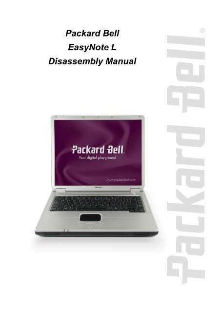
<strong>Packard</strong> <strong>Bell</strong><br />
<strong>EasyNote</strong> L<br />
<strong>Disassembly</strong> <strong>Manual</strong>
Table of Contents<br />
Overview 2<br />
Technician Notes 2<br />
<strong>Disassembly</strong> Instructions 2<br />
Reassembly Instructions 2<br />
Required Tools 2<br />
Hazardous Voltage 3<br />
Avo<strong>id</strong> Electrostatic Discharge 3<br />
Power Supply Unit 3<br />
Removing the Battery 4<br />
Removing the Memory Module 4<br />
Removing the Hard Disk Drive 5<br />
Removing the Keyboard 5<br />
Removing the Optical Disk Drive 7<br />
Removing the LCD Module 7<br />
Removing the LCD Panel 9<br />
Removing the CPU 9<br />
Removing the Top Cover 11<br />
Removing the Touchpad 12<br />
Removing the Chipset Heat Sink 13<br />
Removing the WLAN Card 13<br />
Removing the MDC Modem 14<br />
Removing the Main Board 14<br />
Notice 16<br />
<strong>Packard</strong> <strong>Bell</strong> <strong>EasyNote</strong> L <strong>Disassembly</strong> <strong>Manual</strong><br />
1
Overview<br />
This document contains step-by-step service instructions for the <strong>EasyNote</strong> L. The instructions are<br />
illustrated where necessary with images of the part that is being removed or disassembled.<br />
<strong>Packard</strong> <strong>Bell</strong> reserves the right to make changes to the <strong>EasyNote</strong> L without notice.<br />
Technician Notes<br />
Only technicians <strong>au</strong>thorized by NEC Computers International B.V. should attempt to repair this<br />
equipment. All troubleshooting and repair procedures are detailed to allow only subassembly/module<br />
level repair. Bec<strong>au</strong>se of the complexity of the indiv<strong>id</strong>ual boards and subassemblies, no one should<br />
attempt to make repairs at the component level or to make modifications to any printed wiring board.<br />
Improper repairs can create a safety hazard. Any indication of component replacement or printed wiring<br />
board modifications may vo<strong>id</strong> any warranty or exchange allowances.<br />
<strong>Disassembly</strong> Instructions<br />
When disassembling the system unit, follow these general rules:<br />
n Turn off the power and disconnect all cables and peripherals.<br />
n Label all removed connectors. Note where the connector goes and in what position it was<br />
installed.<br />
n Do not disassemble the system into parts that are smaller than those specified in the<br />
instructions.<br />
Reassembly Instructions<br />
Reassembly is the reverse of the disassembly process. Use care to ensure that all cables and screws are<br />
returned to their proper positions. Check that no tools or any loose parts have been left ins<strong>id</strong>e the casing.<br />
Check that everything is properly installed and tightened.<br />
Required Tools<br />
All disassembly procedures can be performed using the following tools:<br />
n PH 0 x 40 Philips screwdriver<br />
n 4.0 x 60 Flat-bladed screwdriver<br />
n 2.0 x 30 Flat-bladed screwdriver<br />
n SW 5.0 Spacer screwdriver<br />
n Small tweezers<br />
<strong>Packard</strong> <strong>Bell</strong> <strong>EasyNote</strong> L <strong>Disassembly</strong> <strong>Manual</strong><br />
2
Hazardous Voltage<br />
There is hazardous voltage present ins<strong>id</strong>e the<br />
computer when it is connected to an AC supply, even<br />
when the computer’s power switch is off. Exposure to<br />
hazardous voltage could c<strong>au</strong>se personal injury. To<br />
avo<strong>id</strong> risk of injury, contact an Authorized Service<br />
Prov<strong>id</strong>er for proper (un)installation of optional<br />
hardware devices.<br />
Avo<strong>id</strong> Electrostatic Discharge<br />
Electrostatic electricity can easily damage circuit cards<br />
and integrated circuits (ICs). To reduce risk of<br />
damage, store them in protective packaging whenever<br />
they are not installed in your system.<br />
Add-in cards can be extremely sensitive to ESD and<br />
always require careful handling. After removing the<br />
card from the computer, place the card flat on a<br />
grounded, static-free surface, component-s<strong>id</strong>e up. Use<br />
a conductive foam pad if available, but not the card<br />
wrapper. Do not sl<strong>id</strong>e the card over any surface.<br />
Before you install or remove memory modules, v<strong>id</strong>eo<br />
memory, disk drives, circuit cards or other devices,<br />
protect them from static electricity. To do so, make<br />
sure your computer’s power switch is OFF. Then,<br />
unplug the computer’s AC power cord. Before picking<br />
up the device you (un)install, you should wear an antistatic<br />
wrist wrap (available at electronic supply stores).<br />
Be sure to connect the wrist wrap to an unpainted<br />
metal portion of the computer casing. As an<br />
alternative, you can dissipate electrostatic build-up by<br />
touching an unpainted metal portion of the computer<br />
casing with one hand. Then touch the device you are<br />
(un)installing with the other hand, and maintain<br />
continuous contact with it until it is (un)installed in the<br />
computer.<br />
Power Supply Unit<br />
Under no circumstances should you attempt to<br />
disassemble the power supply. The power supply<br />
contains no user-serviceable parts. Ins<strong>id</strong>e the power<br />
supply are hazardous voltages that can c<strong>au</strong>se serious<br />
personal injury. Always return a defective power<br />
supply to your dealer.<br />
<strong>Packard</strong> <strong>Bell</strong> <strong>EasyNote</strong> L <strong>Disassembly</strong> <strong>Manual</strong><br />
WARNING<br />
Ensure that the computer is disconnected<br />
from its power source and from all<br />
telecommunications links, networks, or<br />
modem lines whenever the casing cover is<br />
removed. Do not operate the computer with<br />
the cover removed.<br />
AVERTISSEMENT<br />
Assurez-vous que le système est<br />
débranché de son alimentation ainsi que de<br />
toutes les liaisons de télécommunication,<br />
des rése<strong>au</strong>x, et des lignes de modem avant<br />
d’enlever le capot. Ne pas utiliser le<br />
système quand le capot est enlevé.<br />
WARNUNG<br />
Das System darf weder an eine<br />
Stromquelle angeschlossen sein noch eine<br />
Verbindung mit einer<br />
Telekommunikationseinrichtung, einem<br />
Netzwerk oder einer Modem-Leitung haben,<br />
wenn die Gehäuseabdeckung entfernt wird.<br />
Nehmen Sie das System nicht ohne die<br />
Abdeckung in Betrieb.<br />
ADVERTENCIA<br />
Asegúrese de que cada vez que se quite la<br />
cubierta del chasis, el sistema haya s<strong>id</strong>o<br />
desconectado de la red de alimentación y<br />
de todos lo enlaces de telecomunicaciones,<br />
de red y de líneas de módem. No ponga en<br />
funcionamiento el sistema mientras la<br />
cubierta esté quitada.<br />
WAARSCHUWING<br />
Zorg er voor dat alle verbindingen van en<br />
naar de computer (stroom, modem,<br />
netwerk, etc) verbroken worden voordat de<br />
behuizing geopend wordt. Zet de computer<br />
nooit aan als de behuizing geopend is.<br />
AVVERTENZA<br />
Prima di rimuovere il coperchio del telaio,<br />
assicurarsi che il sistema sia scollegato<br />
dall’alimentazione, da tutti i collegamenti di<br />
comunicazione, reti o linee di modem. Non<br />
avviare il sistema senza aver prima messo<br />
a posto il coperchio.<br />
3
Removing the Battery<br />
Perform the following steps to remove the battery:<br />
i. Make sure to power off the <strong>EasyNote</strong> L.<br />
ii. Disconnect the AC adapter and all peripherals.<br />
iii. Turn the unit over.<br />
iv. Unlock the battery and sl<strong>id</strong>e it out.<br />
Fig. 1 Releasing the battery.<br />
Removing the Memory Module<br />
To remove the memory module, first remove the battery (see Removing the Battery), then perform the<br />
following steps:<br />
1. Remove the screw securing the memory compartment cover.<br />
Fig. 2 Memory compartment cover screw location.<br />
ii. Release with your fingers the s<strong>id</strong>e locks located on the memory slot. As you release the<br />
locks, the module will <strong>au</strong>tomatically pop up and stay in a 45º angle position.<br />
<strong>Packard</strong> <strong>Bell</strong> <strong>EasyNote</strong> L <strong>Disassembly</strong> <strong>Manual</strong><br />
4
Fig. 3 Releasing the memory s<strong>id</strong>e locks.<br />
iii. Pull out the memory module from its slot.<br />
Removing the Hard Disk Drive<br />
To remove the hard disk drive, first remove the battery (see Removing the Battery), then perform the<br />
following steps:<br />
1. Remove the 2 screws securing the hard disk drive compartment cover.<br />
Fig. 4 Removing the hard disk drive cover.<br />
2. Remove the 2 screws that secure the hard disk drive.<br />
3. Carefully pull the Mylar to sl<strong>id</strong>e the hard disk drive assembly out of the bay.<br />
Fig. 5 Removing the HDD assembly.<br />
Removing the Keyboard<br />
To remove the keyboard, first remove the battery (see Removing the Battery), then perform the following<br />
steps:<br />
<strong>Packard</strong> <strong>Bell</strong> <strong>EasyNote</strong> L <strong>Disassembly</strong> <strong>Manual</strong><br />
5
1. Release the keyboard cover from the rear of the notebook.<br />
Fig. 6 Releasing the keyboard cover.<br />
2. Open the notebook and tilt the LCD module entirely backward.<br />
3. Carefully remove the keyboard cover.<br />
Fig. 7 Lifting the keyboard.<br />
4. Pull the keyboard up with your fingertips. Be careful not to break the keyboard locks. Since the<br />
keyboard is connected to the computer through a flat cable, your have to be careful to not<br />
break this cable.<br />
5. With the keyboard lying on top of the palm rest, disconnect the keyboard flat cable from the<br />
unit (see Fig. 8). To do so:<br />
i. Set the flat cable connector on the main board in the unlocked position (#1, Fig. 9).<br />
ii. Remove the keyboard cable from the keyboard connector on the main board (#2, Fig. 9).<br />
Fig. 8 Disconnecting the keyboard flat cable.<br />
<strong>Packard</strong> <strong>Bell</strong> <strong>EasyNote</strong> L <strong>Disassembly</strong> <strong>Manual</strong><br />
6
Fig. 9 Disconnecting the flat cable.<br />
Removing the Optical Disk Drive<br />
To remove the optical disk drive, first remove the battery (see Removing the Battery) and remove the<br />
keyboard (see Removing the Keyboard), then perform the following steps:<br />
1. Remove the 2 screws securing the optical disk drive.<br />
Fig. 10 Releasing the optical disk drive.<br />
2. Flip over the unit, open the LCD and push the optical disk drive module out from the base unit.<br />
Fig. 11 Pushing the optical disk drive out.<br />
Removing the LCD Module<br />
To remove the LCD module, first remove the battery (see Removing the Battery), remove the keyboard<br />
(see Removing the Keyboard), then perform the following steps:<br />
1. Remove the 6 screws securing the heat plate.<br />
<strong>Packard</strong> <strong>Bell</strong> <strong>EasyNote</strong> L <strong>Disassembly</strong> <strong>Manual</strong><br />
7
Fig. 12 Removing the heat plate screws.<br />
2. Close the LCD, flip over the notebook and remove the 2 screws securing the LCD module.<br />
3. Remove the 2 screws on the back.<br />
Fig. 13 Removing the LCD module screws (bottom).<br />
Fig. 14 Removing the LCD module screws (rear).<br />
4. Open up the LCD and gently disconnect the LCD power cable and the 2 WLAN antenna<br />
cables.<br />
Fig. 15 Location WLAN antenna cables and LCD power cable.<br />
Note The black WLAN antenna cable is on the MAIN connector, the grey one on the AUX connector.<br />
<strong>Packard</strong> <strong>Bell</strong> <strong>EasyNote</strong> L <strong>Disassembly</strong> <strong>Manual</strong><br />
8
5. Carefully lift the LCD module away from the unit.<br />
Removing the LCD Panel<br />
To remove the LCD panel, first remove the LCD module (see Removing the LCD Module), then perform<br />
the following steps:<br />
1. Use a pin to remove the rubber covers on the LCD module.<br />
Fig. 16 Location of rubber covers and screws.<br />
2. After removing the rubber covers, remove the screws and release the LCD cover carefully.<br />
3. Remove the inverter board after unscrewing the screw and disconnecting all connectors.<br />
Fig. 17 Removing the inverter board.<br />
4. Carefully lift the LCD panel.<br />
5. Remove the screws on both s<strong>id</strong>es of the LCD panel in order to release the LCD hinges.<br />
Fig. 18 Removing the LCD panel hinges.<br />
Removing the CPU<br />
To remove the CPU first remove the battery (see Removing the Battery) and remove the keyboard (see<br />
Removing the Keyboard), then perform the following steps:<br />
<strong>Packard</strong> <strong>Bell</strong> <strong>EasyNote</strong> L <strong>Disassembly</strong> <strong>Manual</strong><br />
9
1. Remove the screws securing the heat plate (see Fig. 12).<br />
2. After taking out the heat plate, remove the 3 CPU fan screws, disconnect the CPU fan<br />
connector and remove the CPU fan.<br />
Fig. 19 Location CPU fan screws.<br />
3. Remove the 3 remaining screws on the CPU heat sink and take it out.<br />
Fig. 20 Location remaining CPU heat sink screws.<br />
4. Unlock the CPU socket by turning captured screw head fully counter clockwise with a flatbladed<br />
screwdriver.<br />
Fig. 21 Removing the CPU.<br />
<strong>Packard</strong> <strong>Bell</strong> <strong>EasyNote</strong> L <strong>Disassembly</strong> <strong>Manual</strong><br />
10
5. Take out the CPU very carefully.<br />
Note Beware of the screws you use on the CPU heat sink! Make sure to use the original screws,<br />
otherwise it might c<strong>au</strong>se damage to the CPU die.<br />
Note Use extra care when unlocking or locking the CPU socket bec<strong>au</strong>se the screwdriver might<br />
c<strong>au</strong>se damage on CPU’s edge each <strong>tim</strong>e when unlocking or locking the CPU socket..<br />
Removing the Top Cover<br />
To remove the top cover, first remove the battery (see Removing the Battery), remove the hard disk drive<br />
(see Removing the Hard Disk Drive), remove the optical disk drive (see Removing the Optical Disk Drive),<br />
remove the keyboard (see Removing the Keyboard) and remove the LCD module (see Removing the<br />
LCD Module), then perform the following steps:<br />
1. Remove all screws (2 small and 8 larger ones) on the bottom of the base unit.<br />
Fig. 22 Location bottom cover screws.<br />
2. Flip over and open up the notebook completely so that the LCD is levelled with the bottom of<br />
the casing.<br />
3. Release all screws (2 large and 3 smaller ones) on the top cover.<br />
<strong>Packard</strong> <strong>Bell</strong> <strong>EasyNote</strong> L <strong>Disassembly</strong> <strong>Manual</strong><br />
11
Fig. 23 Location top cover screws.<br />
4. Disconnect the touchpad connector and remove the flat cable (same principle as described in<br />
Fig 9).<br />
5. Carefully lift the top cover.<br />
Fig. 24 Disconnecting the touchpad cable.<br />
Removing the Touchpad<br />
To remove the touchpad, first remove the top cover (see Removing the Top Cover), then perform the<br />
following steps:<br />
1. Remove the screws securing the touchpad to the top cover.<br />
<strong>Packard</strong> <strong>Bell</strong> <strong>EasyNote</strong> L <strong>Disassembly</strong> <strong>Manual</strong><br />
12
Fig. 25 Location touchpad screws.<br />
2. Carefully separate the touchpad module from the top cover.<br />
Removing the Chipset Heat Sink<br />
To remove the chipset heat sink, first remove the top cover (see Removing the Top Cover), then perform<br />
the following steps:<br />
1. Remove the 2 screws securing the chipset heat sink to the main board.<br />
Fig. 26 Location chipset heat sink screws.<br />
Removing the WLAN Card<br />
To remove the WLAN card, first remove the LCD module (see Removing the LCD Module) and then<br />
perform the following steps:<br />
1. Release with your fingers the s<strong>id</strong>e locks securing the WLAN card. As you release the locks,<br />
the card will <strong>au</strong>tomatically pop up and stay in a 45º angle position.<br />
<strong>Packard</strong> <strong>Bell</strong> <strong>EasyNote</strong> L <strong>Disassembly</strong> <strong>Manual</strong><br />
13
Fig. 27 Releasing the WLAN s<strong>id</strong>e locks.<br />
2. Carefully take out the WLAN card from the slot.<br />
Removing the MDC Modem<br />
To remove the modem, first remove the top cover (see Removing the Top Cover), then perform the<br />
following steps:<br />
1. Remove the 2 screws securing the modem to the main board.<br />
Fig. 28 Location modem card screws.<br />
2. Turn over the modem and gently disconnect the MDC cable.<br />
Removing the Main Board<br />
To remove the main board, first remove the top cover (see Removing the Top Cover) and then perform<br />
the following steps:<br />
1. Remove the hex screws from the VGA port.<br />
2. Remove all screws on the HDD holder and separate it carefully from the main board.<br />
<strong>Packard</strong> <strong>Bell</strong> <strong>EasyNote</strong> L <strong>Disassembly</strong> <strong>Manual</strong><br />
14
Fig. 29 Screw location on the HDD holder.<br />
3. Disconnect the speaker and L<strong>id</strong> switch connectors from the main board and remove the<br />
screws encircled in the following picture.<br />
Fig. 30 Screws and connectors on main board.<br />
4. Lift the main board and remove it away from the unit.<br />
Fig. 31 Removing the main board.<br />
<strong>Packard</strong> <strong>Bell</strong> <strong>EasyNote</strong> L <strong>Disassembly</strong> <strong>Manual</strong><br />
15
Notice<br />
The information in this gu<strong>id</strong>e is subject to change without notice.<br />
This gu<strong>id</strong>e contains information protected by copyright. No part of this gu<strong>id</strong>e may be photocopied or<br />
reproduced in any form or by any means without prior written consent from NEC Computers International<br />
B.V.<br />
NEC COMPUTERS INTERNATIONAL B.V. SHALL NOT BE LIABLE FOR TECHNICAL OR EDITORIAL<br />
ERRORS OR OMISSIONS CONTAINED HEREIN; NOR FOR INCIDENTAL OR CONSEQUENTIAL<br />
DAMAGES RESULTING FROM THE FURNISHING, PERFORMANCE, OR USE OF THIS MATERIAL.<br />
Copyright © 2005 NEC Computers International B.V. All rights reserved.<br />
<strong>Packard</strong> <strong>Bell</strong> is a trademark of NEC Computers International B.V.<br />
The names of actual companies and products mentioned herein may be trademarks and/or registered<br />
trademarks of their respective owners.<br />
The software described in this gu<strong>id</strong>e is furnished under a license agreement or nondisclosure agreement.<br />
The software may be used or copied only in accordance with the terms of the agreement.<br />
<strong>EasyNote</strong> L <strong>Disassembly</strong> <strong>Manual</strong><br />
Author: Juan M. Calviño & Thomas Herbers - ECCS<br />
First Edition: October 2005<br />
Document Part Number: 7400360000<br />
Version: 1.0<br />
<strong>Packard</strong> <strong>Bell</strong><br />
A division of NEC Computers International B.V.<br />
<strong>Packard</strong> <strong>Bell</strong> <strong>EasyNote</strong> L <strong>Disassembly</strong> <strong>Manual</strong><br />
16


