Wireless IP Camera Version 1.00 (English) - PROLiNK
Wireless IP Camera Version 1.00 (English) - PROLiNK
Wireless IP Camera Version 1.00 (English) - PROLiNK

Create successful ePaper yourself
Turn your PDF publications into a flip-book with our unique Google optimized e-Paper software.
<strong>Wireless</strong> <strong>IP</strong> <strong>Camera</strong><br />
<strong>Version</strong> <strong>1.00</strong><br />
(<strong>English</strong>)<br />
BEFORE GETTING STARTED<br />
This UM is designed to aid you to get started with the device. If you experience problems following these guides or<br />
need further information pertaining to the device, please visit our website at www.prolink2u.com. All specifications<br />
are subject to the manufacturer’s configuration at the time of shipping and may change without prior notice, written<br />
or otherwise.
Table of Contents<br />
Table of Contents .............................................................................................................................................................. 1<br />
1. Introduction ................................................................................................................................................................... 1<br />
1.1. The Differences .................................................................................................................................................. 1<br />
2. Installation & Setup ....................................................................................................................................................... 2<br />
2.1. Hardware Overview .......................................................................................................................................... 2<br />
2.2. Quick Installation and Usage ............................................................................................................................ 3<br />
2.2.1. First, Connect the <strong>IP</strong> CAM to the home/office network ............................................................................ 3<br />
2.2.2. Second, Install the LiveView Software on the notebook/PC ...................................................................... 3<br />
2.2.3. Third, Use LiveView program to see the video .......................................................................................... 4<br />
2.2.4. Seeing the video in a remote location ....................................................................................................... 4<br />
2.3. <strong>Wireless</strong> Connection .......................................................................................................................................... 5<br />
2.3.1. First, set the WiFi security settings on the web configuration page. ........................................................ 5<br />
2.3.2. Second, test if the WiFi settings are correct .............................................................................................. 5<br />
2.3.3. Third, unplug the Ethernet cable ............................................................................................................... 6<br />
3. Web Configurations ...................................................................................................................................................... 7<br />
3.1. Information ....................................................................................................................................................... 8<br />
3.2. Video Display ..................................................................................................................................................... 9<br />
3.3. Network ........................................................................................................................................................... 10<br />
3.4. WiFi Security .................................................................................................................................................... 12<br />
3.5. Advanced Network .......................................................................................................................................... 15<br />
3.6. Video Settings.................................................................................................................................................. 16<br />
3.7. Night Mode Control ......................................................................................................................................... 18<br />
3.8. 3GPP/RTSP Settings......................................................................................................................................... 19<br />
3.9. Email/Ftp Alarm .............................................................................................................................................. 20<br />
3.10. NAS Settings ................................................................................................................................................ 22<br />
3.11. SD-Card Settings .......................................................................................................................................... 24<br />
3.12. Scheduling ................................................................................................................................................... 26<br />
3.13. Date/Time ................................................................................................................................................... 28<br />
3.14. Admin .......................................................................................................................................................... 29<br />
3.15. Upgrade....................................................................................................................................................... 30<br />
3.16. Reboot ......................................................................................................................................................... 32<br />
3.17. Safe Mode ................................................................................................................................................... 33<br />
3.18. Set To Factory Default ................................................................................................................................. 34
4. Features & Specifications ............................................................................................................................................ 35<br />
4.1. Features........................................................................................................................................................... 35<br />
4.2. Specifications .................................................................................................................................................. 35<br />
5. Package Contents ........................................................................................................................................................ 37<br />
Appendix A. List of Tested NAT/Router Devices .............................................................................................................. 38<br />
Appendix B. Maximum Allowed Video Users .................................................................................................................. 39<br />
Appendix C. Performance Information ............................................................................................................................ 40<br />
Appendix D. Troubleshooting .......................................................................................................................................... 41<br />
Appendix E. 3GPP/ISMA Operation ................................................................................................................................. 48<br />
Appendix F. Third Party and Embedded Web Page Integration ...................................................................................... 49<br />
Worldwide Customer Care Centers ................................................................................................................................. 50
1. Introduction<br />
The <strong>PROLiNK</strong>® PIC1005WN <strong>Wireless</strong> <strong>IP</strong> <strong>Camera</strong> (will be referred to as “<strong>IP</strong> <strong>Camera</strong>” for the entire document) is<br />
designed with the “user-friendly” idea deep in mind. The user can install the <strong>IP</strong> <strong>Camera</strong> easily on his/her home network<br />
and then access the <strong>IP</strong> <strong>Camera</strong> anywhere in the world through the accompanied video management software -<br />
LiveView program without setting some complicated DNS name or changing the router’s settings. It’s just a plug &<br />
play action.<br />
With 3GPP/ISMA support, users can see the video of the <strong>IP</strong> camera on any 3G mobile phone anywhere, anytime. The<br />
big difference is that there is software for downloading to the mobile phone so that the fixed <strong>IP</strong> address is not needed<br />
for the <strong>IP</strong> camera. The video settings including frame rate, resolution and bandwidth could be different for PC<br />
monitoring and mobile viewing.<br />
For indoor surveillance and remote monitoring, the <strong>IP</strong> <strong>Camera</strong> provides the best image quality in its class, and<br />
excellent performance. The <strong>IP</strong> <strong>Camera</strong> also provides the best bandwidth efficiency, it offers 640x480 resolutions, 30 fps<br />
frame rate, real MPEG4 image compression ability. The built-in microphone enables remote users to not only view, but<br />
also listen for additional monitoring options.<br />
The NAS storage function can easily turn any NAS device to a NVR device. The schedule function provides full<br />
scheduling of email/ftp sending, motion detection and NAS recording event. With the built-in Web server, the <strong>IP</strong><br />
<strong>Camera</strong> can also be managed from a standard web browser on a Windows computer.<br />
With the very low light sensitive video sensor and IR LEDs, the <strong>IP</strong> <strong>Camera</strong> can work day and night, satisfying all home<br />
security and indoor surveillance needs. With the motor controlled IR-cut filter, the day-time video quality is not<br />
affected.<br />
The <strong>IP</strong> Cam(w) provides both wireless IEEE 802.11 b/g and wired Ethernet network interfaces for flexible installation. It<br />
supports the WEP and WPA (Wi-Fi Protected Access) security modes to provide the best security for wireless networks.<br />
(<strong>IP</strong> Cam model only support wired Ethernet interface)<br />
The <strong>IP</strong> <strong>Camera</strong> provides motion detection function. Users can easily setup this function and receive the notification<br />
with the snapshot images through email and/or ftp when some motion events are detected.<br />
The <strong>IP</strong> <strong>Camera</strong> is ideal for securing small businesses, home offices and residences over a local area network and/or the<br />
Internet.<br />
1.1. The Differences<br />
It’s very easy to see the video of the <strong>IP</strong> <strong>Camera</strong>, you only need to key in the ID/Password of the <strong>IP</strong> CAM<br />
anywhere in the world, and you DO NOT need to remember the <strong>IP</strong> address or domain name or DDNS name or<br />
port number. And you do not need to modify the settings (like port mapping, fixed <strong>IP</strong>, DDNS, virtual server) of<br />
the NAT/router devices, it’s just a plug & play usage.<br />
EN 1
2. Installation & Setup<br />
The <strong>IP</strong> <strong>Camera</strong> is designed to be very easy to install and use. First, let’s see the major components of the <strong>IP</strong> <strong>Camera</strong><br />
products.<br />
2.1. Hardware Overview<br />
Figure 2-1: <strong>IP</strong> <strong>Camera</strong> Hardware Overview<br />
1 Microphone For receiving the audio/voice. Effective distance is about 5 meters.<br />
2 Infrared LED There are totally 11 IR LEDs that can provide approximately 10m distance night vision.<br />
3 Lens The lens is inside the mask and the focus of the lens is fixed, you DO NOT need to spend time to<br />
adjust the focus, the effective focus range is from 30cm to infinity.<br />
4 Light Sensor This light detector can detect when the light is becoming dark and turn on the IR LEDs<br />
automatically<br />
5 Status indication LED<br />
(Red)<br />
6 Ethernet indication LED<br />
(Blue)<br />
This LED is to indicate the Internet connection status. When the Internet connection is connected,<br />
the LED will be constant red light. If there is any Internet connection problem, the LED will be<br />
blinking red light.<br />
This LED is to indicate if the Ethernet link is ok and packet traffic is sending/receiving. When the<br />
Ethernet cable is connected, the LED is constant blue light. When there is packet<br />
sending/receiving, the LED is blinking blue light.<br />
7 Wall mount This is the place to hang the <strong>IP</strong> <strong>Camera</strong> on the ceiling or on the wall.<br />
8 Antenna This is the 802/11 b/g wireless antenna.<br />
9 Micro-SD card slot For inserting the micro SD-Card. (support up to 16G bytes)<br />
10 ID & Password Label This label contains the information of the <strong>IP</strong> <strong>Camera</strong>, including the unique <strong>Camera</strong> ID and default<br />
Password. User can always refer from this label if forgotten <strong>Camera</strong> ID and Password.<br />
11 Bracket screw jack This is the position to screw in the bracket of the <strong>IP</strong> <strong>Camera</strong>. With the bracket, you can put the <strong>IP</strong><br />
<strong>Camera</strong> on the desk, on the wall or on the ceiling. (Bracket not provided)<br />
12 Antenna Jack This is the place to hold the wireless antenna. The antenna must be plugged to let the 802.11 b/g<br />
wireless work.<br />
13 Power Jack This is the place to plug in the power adaptor. The power needed for this <strong>IP</strong> <strong>Camera</strong> is 5V/1.0A,<br />
please make sure you are using the correct power adaptor.<br />
14 Reset button This is the button to reset the <strong>IP</strong> <strong>Camera</strong> to default factory settings. You need to use a small stick<br />
like pencil or tooth stick to press the reset button for more than 3 seconds to enable the reset<br />
function. Usually when you forgot the administrator account, you will probably need to reset to<br />
the default factory settings. Please refer to section 3.19 for more details.<br />
15 Ethernet Jack This is the place to plug in the RJ45 Ethernet cable. When the Ethernet link is ok, the Ethernet<br />
indication LED on the front side will be blue light.<br />
EN 2
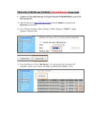
2.2. Quick Installation and Usage<br />
There are only three things that you need to do to see the video from the <strong>IP</strong> <strong>Camera</strong>.<br />
1. Connect the <strong>IP</strong> <strong>Camera</strong> to the home/office network.<br />
2. Install the LiveView Software on the notebook/PC.<br />
3. Key in the ID/password of the <strong>IP</strong> <strong>Camera</strong> on the LiveView, and then you can see the video.<br />
2.2.1. First, Connect the <strong>IP</strong> CAM to the home/office network<br />
Please connect the <strong>IP</strong> <strong>Camera</strong> accessories to the <strong>IP</strong> <strong>Camera</strong> body correctly, including the power<br />
adapter and Ethernet cable (as shown in Figure 2-2). And connect the other end of the Ethernet cable<br />
to the home network or office network. Usually, this Ethernet cable is plugged into a home<br />
NAT/router device or an Ethernet switch if in the office (as shown in Figure 2-3). Since the default<br />
settings of the <strong>IP</strong> <strong>Camera</strong> use DHCP function and very often there is a DHCP server on most of the<br />
Home/office network, the <strong>IP</strong> <strong>Camera</strong> should be connected to the Internet immediately. The Internet<br />
status LED is constant red light to indicate this good connection status. If the LED is blinking, please<br />
refer to section 3.3~3.5 to try other network settings.<br />
Figure 2-2: <strong>IP</strong> <strong>Camera</strong> connection diagram.<br />
Figure 2-3: Connect Ethernet cable to a switch/router.<br />
2.2.2. Second, Install the LiveView Software on the notebook/PC<br />
Please insert the installation CD into the CD-ROM drive in your notebook<br />
or personal computer (must be running Microsoft Windows OS). Execute<br />
the program LiveViewInstaller-xxx.exe on the disk. The program will popup<br />
some windows about the installation options, please press the “next”<br />
button to proceed with the installation. After the installation is complete,<br />
there will be a LiveView icon on the desktop of your computer screen,<br />
please execute this icon. The LiveView program will run immediately.<br />
Figure 2-4: Setup CD<br />
EN 3
2.2.3. Third, Use LiveView program to see the video<br />
If the computer and <strong>IP</strong> <strong>Camera</strong> are connected to the same<br />
network, the <strong>IP</strong> <strong>Camera</strong> ID will be displayed in the “Auto Search”<br />
list. You can double click the “Auto Search” to search all the<br />
connected <strong>IP</strong> <strong>Camera</strong>s any time. The only thing left right now<br />
for seeing the video is to double click the <strong>IP</strong> <strong>Camera</strong> ID item in<br />
the “Auto Search” list. For example, if the <strong>IP</strong> <strong>Camera</strong> ID is 001-<br />
001-029, you can then double click the 001001029 item in the<br />
“Auto Search” list to view the video. A window asking for<br />
password input will pop up. Please key-in the password into this<br />
field and click “ok”. The video will then be displayed on the<br />
window. Password can be retrieved from label located at rear of<br />
the <strong>IP</strong> <strong>Camera</strong> as shown in Figure 2-5.<br />
Notice<br />
Figure 2-5: <strong>Camera</strong> ID & Password<br />
1. You can modify this play-video password by entering into the web configuration pages. Please refer<br />
to section 3.6 for more information.<br />
2. You can also add the <strong>IP</strong> <strong>Camera</strong> into the <strong>Camera</strong>List in the LiveView Software to have more<br />
convenient video display, please refer to the user manual of the LiveView Software for more<br />
functions.<br />
2.2.4. Seeing the video in a remote location<br />
After the <strong>IP</strong> <strong>Camera</strong> is installed and you can see the video from the LiveView Software in the local<br />
network, it’s very easy to see the video in a remote location. All you need to do is add a camera item<br />
in the “<strong>Camera</strong>List” folder of the LiveView Software; key in the <strong>IP</strong> <strong>Camera</strong> ID and Password (refer to<br />
2.2.3 for <strong>Camera</strong> ID and Password). And then double click this camera item. You will then see the<br />
<strong>Camera</strong> video immediately. No further NAT/router setting modifications are needed.<br />
Figure 2-6: LiveView Software User Interface<br />
EN 4
Figure 2-7: Pop-up play-video password window<br />
2.3. <strong>Wireless</strong> Connection<br />
The <strong>IP</strong> <strong>Camera</strong> can also be connected to the home/office network through the 802.11 b/g wireless connection.<br />
There are only three things that you need to do to have the wireless connection:<br />
1. Set the WiFi security settings on the web configuration page.<br />
2. Test if the WiFi settings are correct.<br />
3. Unplug the Ethernet cable.<br />
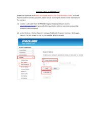
2.3.1. First, set the WiFi security settings on the web configuration page.<br />
Make sure there is a WiFi AP/router on your home/office network. Write down the WiFi security<br />
parameters used in this WiFi AP/router, including the SSID, security mode, encryption protocols and<br />
the “key” values. The supported WiFi security mode of the <strong>IP</strong> <strong>Camera</strong> is WEP (64 bits and 128 bits) and<br />
WPA-PSK (TK<strong>IP</strong> and AES). In most of the home/office WiFi environment, this is quite enough.<br />
The easiest way to set the WiFi settings on the <strong>IP</strong> <strong>Camera</strong> is through LiveView Software. Right-click the<br />
searched <strong>IP</strong> <strong>Camera</strong> in the “Auto Search” list and click the “Web Configure” to open the login window<br />
of the <strong>IP</strong> <strong>Camera</strong>. Fill in all the WiFi security parameters you have written down. The WiFi configuration<br />
is complete now.<br />
Please refer to section 3.4 for more detailed description if needed.<br />
2.3.2. Second, test if the WiFi settings are correct<br />
You can now test if the above WiFi settings are correct. Click the “WiFi test” on the “WiFi Security”<br />
settings web page. The testing result will be displayed in less than 60 seconds. If the test is failed,<br />
please check the WiFi security parameters and test again.<br />
EN 5
2.3.3. Third, unplug the Ethernet cable<br />
If the WiFi test is successful, you can then enable<br />
the WiFi connection by unplugging the Ethernet<br />
cable from the <strong>IP</strong> <strong>Camera</strong>. The <strong>IP</strong> <strong>Camera</strong> will detect<br />
the Ethernet cable unplugged condition and start<br />
the WiFi connection. After the WiFi is connected,<br />
the <strong>IP</strong> <strong>Camera</strong> will connect to the Internet<br />
immediately.<br />
Figure 2-8: Unplug the Ethernet cable to enable<br />
the WiFi function<br />
Notice<br />
1. Please remember that the WiFi connection will use a different <strong>IP</strong> address, you will need to do the<br />
“Auto Search” function in the LiveView again to find the <strong>IP</strong> <strong>Camera</strong> again after the WiFi is connected.<br />
2. If you want to switch back to the wired Ethernet connection, just plug in the Ethernet cable into the<br />
<strong>IP</strong> <strong>Camera</strong> again. Do not need to disable the WiFi function on the web pages.<br />
EN 6
3. Web Configurations<br />
You can login into the web configuration page by directly key-in the <strong>IP</strong> address of the <strong>IP</strong> <strong>Camera</strong> or right-click the<br />
searched <strong>IP</strong> <strong>Camera</strong> in the “Auto Search” list of the LiveView Software and click the “Web Configure” to open the login<br />
window of the <strong>IP</strong> <strong>Camera</strong>.<br />
Figure 3-1: Open the web configuration page from LiveView Software<br />
The default login account is “admin”, leave the Password field empty.<br />
Figure 3-2: <strong>IP</strong> <strong>Camera</strong> Web configuration login page<br />
EN 7
3.1. Information<br />
The first page of the web configuration of the <strong>IP</strong> <strong>Camera</strong> is the information page. You can see the model<br />
name/firmware version, <strong>IP</strong> <strong>Camera</strong> ID, registration status, network type and current video settings (bandwidth,<br />
resolution) in this page.<br />
The <strong>IP</strong> <strong>Camera</strong> can be viewed remotely by the LiveView Software only when the <strong>IP</strong> <strong>Camera</strong> is registered. If this<br />
<strong>IP</strong> <strong>Camera</strong> is not registered, please check the Ethernet wiring of your network environment. The “Network type”<br />
field displays the network connection (wired or wireless) and method (DHCP, PPPoE or static <strong>IP</strong>) the <strong>IP</strong> <strong>Camera</strong><br />
is running. The “Video users” field displays the number of connected video viewing users.<br />
Figure 3-3: <strong>IP</strong> <strong>Camera</strong> Information page<br />
EN 8
3.2. Video Display<br />
This display page allows you to view the video display and control the pan/tilt movement of the <strong>IP</strong> <strong>Camera</strong>.<br />
For the first time use of this display on a computer, an ActiveX component will be automatically downloaded<br />
into the browser. This could take some time, depends on the internet speed. The component is downloaded<br />
from a public domain, so that the computer must be connected to the Internet.<br />
If you want to modify the video display screen size, please refer to section 3.6 for more details.<br />
Figure 3-4: Video display page<br />
Pan/tilt control:<br />
1. Control by LiveView – this is to enable/disable the pan/tilt control function by LiveView Software.<br />
2. Speed – this is to control the pan/tilt moving step distance for each pan or tilt movement, fast means<br />
larger step movement.<br />
3. Pan – click this button will let the <strong>IP</strong> <strong>Camera</strong> do one horizontal pan scan movement.<br />
4. Tilt – click this button will let the <strong>IP</strong> <strong>Camera</strong> do one vertical tilt scan movement.<br />
5. Patrol control – you can set up to 5 patrol points that will let the <strong>IP</strong> <strong>Camera</strong> to patrol through these patrol<br />
points. To set the patrol point, first move the <strong>IP</strong> <strong>Camera</strong> to the desired view position by clicking the<br />
different arrow buttons, and then press the “position” button of the specific patrol point. The (x,y) axis<br />
values will be updated accordingly. You can click the (x,y) axis of the patrol point to direct the view to this<br />
specific patrol point directly. After the patrol points are set, you can click the “Patrol” button to start the<br />
patrol through these points one time.<br />
6. Stay xx secs – this is the time for each patrol point to stay before going to next patrol point.<br />
7. Patrol – click this button to start the patrol movement of the <strong>IP</strong> <strong>Camera</strong>.<br />
8. Stop – this will stop the patrol movement.<br />
EN 9
3.3. Network<br />
The Network page allows you to modify the network settings of the wired Ethernet. The default settings use<br />
DHCP to obtain an <strong>IP</strong> address automatically. In most of the home and office network environment, there is a<br />
DHCP server running. In this situation, by using these default settings, the <strong>IP</strong> <strong>Camera</strong> can work immediately in<br />
most of the time.<br />
If the Ethernet cable is unplugged, the <strong>IP</strong> <strong>Camera</strong> will lose connection. But as soon as the Ethernet cable is<br />
plugged in again, the <strong>IP</strong> <strong>Camera</strong> will obtain a new <strong>IP</strong> address immediately.<br />
Figure 3-5: Network settings page for DHCP function<br />
If the network environment does not support DHCP function, you will need to set the network settings of the<br />
<strong>IP</strong> <strong>Camera</strong> manually. Please fill all the fields including “<strong>IP</strong> address”, “Subnet mask”, “Default gateway” and “DNS<br />
server” to let the network work. All these settings must be correct for your network environment, otherwise the<br />
<strong>IP</strong> <strong>Camera</strong> cannot work.<br />
The default setting is “Obtain an <strong>IP</strong> address automatically”.<br />
EN 10
Figure 3-6: Network settings page for fixed <strong>IP</strong> address<br />
EN 11
3.4. WiFi Security<br />
You can use the wireless to connect the <strong>IP</strong> <strong>Camera</strong> to the network. If your network environment has an 802.11<br />
b/g router or AP running, you can check the “Enable WiFi function” button to use the wireless.<br />
Figure 3-7: WiFi security disabled page<br />
In order to use the wireless network, you need to fill the following fields:<br />
1. SSID – this is the ID of the wireless router or AP of your wireless network environment, must be set<br />
correctly.<br />
2. Security mode – this is the security mode used in the wireless router or AP. Need to choose one of the<br />
three modes – None, WEP and WPA-PSK.<br />
WEP: <strong>Wireless</strong> Encryption Protocol.<br />
WPA: WiFi Protected Access.<br />
PSK: Pre-Shared Key.<br />
TK<strong>IP</strong>: Temporal Key Integrity Protocol.<br />
AES: Advanced Encryption Standard.<br />
3. WEP mode – when the WEP mode is chosen, you need also choose between 64-bit (5 char), 64-bit (10 hex),<br />
128-bit (13 char) and 128-bit (26 hex) encryption mode, and then fill the WEP key correctly.<br />
4. WPA-PSK mode - when the WPA-PSK mode is chosen, you need also choose between TK<strong>IP</strong> and AES<br />
encryption mode, and then fill the WPA-PSK key correctly. WPA2-PSK is also supported. But WPA<br />
Enterprise or WPA2 Enterprise is not supported.<br />
All the fields in this page must be filled correctly with the same settings the wireless router or AP using.<br />
EN 12
Figure 3-8: WiFi security enabled page<br />
You can click the “WiFi test” button to check if the <strong>IP</strong> <strong>Camera</strong> can connect to the wireless network for these<br />
settings. You will need to unplug the Ethernet cable to enable the wireless connection after the “WiFi test” is<br />
successful.<br />
You can click the “WiFi scan” button to scan for all the available access points nearby.<br />
If you want to define fixed <strong>IP</strong> address when using WiFi connection, please press the “<strong>IP</strong> address” button and<br />
key in your preferred <strong>IP</strong> address.<br />
After the setting and “Save & Apply”, do not need to restart the <strong>IP</strong> <strong>Camera</strong> to let the WiFi work, only need to<br />
unplug the Ethernet cable.<br />
The default setting is “Disable WiFi Function”.<br />
EN 13
Figure 3-9: WiFi testing page<br />
EN 14
3.5. Advanced Network<br />
In some special situation, your network environment only provides PPPoE connection (ADSL service); there is<br />
no NAT/router available. You will then need to set the PPPoE settings in the “Advanced Network” page. Only<br />
the PPPoE username and password are needed to let PPPoE work. After the “Save & Apply” button is pressed,<br />
the PPPoE function will work immediately. You can check the “Registration status” in the “Information” page to<br />
see if the <strong>IP</strong> <strong>Camera</strong> is registered using the PPPoE connection.<br />
Please be noticed that the DHCP or static <strong>IP</strong> settings in the “Network” page can work together with the PPPoE<br />
connection. Only that the PPPoE has higher priority, so, if the PPPoE is working, the <strong>IP</strong> <strong>Camera</strong> will use PPPoE<br />
to connect to the Internet.<br />
The default setting is “Disable PPPoE”.<br />
Figure 3-10: Advanced network settings page<br />
EN 15
3.6. Video Settings<br />
The <strong>IP</strong> <strong>Camera</strong> is designed to provide high quality video for viewing from LiveView Software. In this page, you<br />
can modify some settings related to the video viewing:<br />
1. Password (play video) – this is the password needed for viewing the video from the LiveView Software.<br />
Together with the <strong>IP</strong> <strong>Camera</strong> ID, you can view the video of this <strong>IP</strong> <strong>Camera</strong> anywhere in the world through<br />
the Internet.<br />
2. Internet speed – this is the Internet bandwidth of your network environment. Higher value will generate<br />
higher video quality. But if your internet connection cannot provide more bandwidth than the specified<br />
value, the video quality could degrade. So, please key in a value that is lower than your internet bandwidth.<br />
3. Select resolution & frame rate automatically – you can let the system select the suitable video resolution<br />
and frame rate automatically for you. The selection is based on the “Internet speed” value. This is the<br />
recommended default setting.<br />
4. Resolution – there are three choices: 160x120, 320x240 and 640x480. If you decide to choose the value<br />
manually, you can choose one of the three values. But, please be noticed that if the Internet speed is slow<br />
(low value), high resolution (640x480) or frame rate could cause very bad video quality.<br />
5. Frame rate – the video frame display rate. Higher value means faster movement and continuity in the<br />
video display.<br />
6. Favor/Preference – choose between “Video motion” and “Image quality”. When the real bandwidth is not<br />
enough for the selected “Internet speed”, the system will need to degrade the video motion or image<br />
quality. This selection will decide if the user want to maintain the “video motion” or “image quality” when<br />
the internet speed is not good enough.<br />
7. Brightness – the brightness of the video, lower value means darker display.<br />
8. Sharpness – the sharpness of the video, higher value means sharper video.<br />
9. Low light sensitivity – The low light sensitivity could be normal, high or very high. When the low light<br />
sensitivity is high, the system could see better video clearance under low light situation, but the moving<br />
object will not be very clear under this low light environment. Under very dark environment, set to “very<br />
high” will get better video clearance. The default value of this setting is “high”.<br />
10. Video color – choose between “colored” and “black & white”.<br />
11. Video flip – can do “normal” or “flip” video display, this is needed if the <strong>IP</strong> <strong>Camera</strong> is hung on the ceiling or<br />
wall.<br />
12. Outdoor/Indoor video – for better video display quality, modify this setting when taking indoor or outdoor<br />
video. The default setting is “Outdoor video”, in most cases; this is also ok for indoor usage. Under some<br />
special cases, there could be some strip lines on the video display when the <strong>IP</strong> <strong>Camera</strong> is taking indoor<br />
video. In this situation, change the setting to “Indoor video” will solve the problem. Please also be noticed<br />
that in “Indoor video” setting, the video display of outdoor view is very vague. For indoor usage, if there is<br />
strong sun light into the room, please select the “Indoor + sun light” choice.<br />
13. Enable/disable audio microphone – you can enable or disable the audio microphone on the <strong>IP</strong> <strong>Camera</strong>. If<br />
disable, there will be no voice on the LiveView video viewing.<br />
14. Enable/disable time display on video – if enabled, the date/time of the system will be displayed on the<br />
left-upper corner of the video.<br />
When this modification is “Save & Apply”-ed, it works immediately, but all the connected video viewing users<br />
will be disconnected.<br />
EN 16
Figure 3-11: Video settings page<br />
EN 17
3.7. Night Mode Control<br />
The <strong>IP</strong> Cam is able to work both in day time and night time. There are some IR LEDs that can let the <strong>IP</strong> camera<br />
see the objects in the night time. This night mode control page is to control when the time the IR LEDs will be<br />
on. There are three ways to control the night mode (IR LEDs):<br />
a) Automatic day and night mode switch: the <strong>IP</strong> cam will automatically turn on the IR LEDs when the<br />
night time is arrived or the environment is becoming dark. There is a light sensor on the <strong>IP</strong> cam that is<br />
doing this light detection.<br />
b) Scheduled time of night mode: the <strong>IP</strong> Cam can also be scheduled to turn on the IR LEDs in a time<br />
range of each day.<br />
c) Manual night mode control: the <strong>IP</strong> Cam can be manually forced to night mode( IR LEDs on ) or day<br />
mode( IR LEDs off ).<br />
In order to get better video color display during day time and night time, there is an ICR(IR Cutter Remover) in<br />
the <strong>IP</strong> Cam. This ICR will be controlled automatically to filter out the IR(Infrared) light during the day time and<br />
allow the IR light to pass during the night time. This make sure the video color quality is excellent compared to<br />
other <strong>IP</strong> camera.<br />
Figure 3-12: Night mode control page<br />
EN 18
3.8. 3GPP/RTSP Settings<br />
The <strong>IP</strong> <strong>Camera</strong> is able to be viewed from a 3G mobile phone, for detailed settings on the 3G mobile phone,<br />
please refer to Appendix E.<br />
Users can disable the 3G mobile access ability in this page. After the 3GPP/RTSP feature is disabled, no 3G<br />
mobile phone is allowed to access the video of the <strong>IP</strong> <strong>Camera</strong>. When this is disabled, the RTSP stream with<br />
MPEG2 audio is still working, please refer to Appendix F for more details about RTSP stream with MPEG2<br />
audio.<br />
When the 3GPP is enabled, the video frame rate, resolution and bandwidth for 3G mobile access could be set<br />
independently from the video settings for LiveView (PC) access. The maximum allowed resolution is 352x255<br />
and maximum allowed bandwidth is 256 kbps. When the audio is enabled for both 3GPP and LiveView (PC)<br />
and the video/audio is displayed in LiveView, the audio will be disabled in 3G mobile display.<br />
The “Access URL” line is the URL address for 3G mobile phone to input for seeing the video of the <strong>IP</strong> <strong>Camera</strong>.<br />
Different 3G mobile may need to input this URL in different way, detailed information could be found in the<br />
user manual of different 3G mobiles. Please be noticed that usually public <strong>IP</strong> address is needed for the <strong>IP</strong><br />
<strong>Camera</strong>, so that the 3G mobile could access the <strong>IP</strong> <strong>Camera</strong>’s video.<br />
The default setting is “Enable 3GPP/RTSP”.<br />
Figure 3-12: 3GPP/RTSP enabled page<br />
EN 19
3.9. Email/Ftp Alarm<br />
The <strong>IP</strong> <strong>Camera</strong> provides the Email/ftp function, you can enable or schedule the Email/ftp ability in this page,<br />
the <strong>IP</strong> <strong>Camera</strong> will then send out an email with a jpeg picture attached in the email and/or send out the jpeg<br />
picture file to an ftp server. The related settings are explained below:<br />
1. Email/FTP trigger – choose between “motion”, “D/I”, “schedule” and “disable”<br />
a) If “motion” is selected, it means that when there is a motion detected, the system will send out the<br />
email and/or ftp with the captured video snapshot.<br />
b) If “D/I” is selected, it means that when there is a Digital input alarm detected, the system will send out<br />
the email and/or ftp with the captured video snapshot. If the D/I alarm is constantly on, the <strong>IP</strong> <strong>Camera</strong><br />
will keep sending out email/ftp message every second for up to 30 seconds.<br />
c) If “schedule” is selected, it means that the email/ftp alarm detection and triggering will be scheduled<br />
by the “scheduling” in section 3.12.<br />
d) ”Disable” will disable the email/ftp alarm.<br />
2. Motion sensitivity – there are three possible choices in this field.<br />
“High” means high sensitivity, i.e., the motion detection is triggered by a very small movement in the<br />
video image. If “High” is selected and the size of the moving object is larger than about 1% of the<br />
whole video area, it is detected. Please be noticed that the real size of the object could be large or<br />
small, anyway, the detection is only based on the relative size of the object. Probably a small pencil<br />
moving near the <strong>IP</strong> <strong>Camera</strong> could be detected, but a moving car far away from the <strong>IP</strong> <strong>Camera</strong> could<br />
not be detected.<br />
“Low” means low sensitivity, i.e., the motion detection is triggered by a very large movement. If the<br />
size of the moving object is larger than about 10% of the whole video area, it is detected. “Median”<br />
means 3% to trigger the detection.<br />
3. Send email message – if this item is enabled, the <strong>IP</strong> <strong>Camera</strong> will send out an email message with the jpeg<br />
picture attached to the specified email account.<br />
4. Email recipient – this is the email address to receive the detection notice message. An email message with<br />
the jpeg picture file named by the date/time of the triggered moment will reach this address.<br />
5. SMTP server – this is the SMTP server that will help to transfer the email message. This server is irrelevant<br />
to the “Email recipient” address.<br />
6. SMTP username/password – this is the account to use the SMTP server to transfer the email message. The<br />
SMTP server and username/password account are only for transfer the email message to the “Email<br />
recipient”, the “Email recipient” could be on another email server or any reachable email address. The<br />
username and password fields could be left empty if no authentication is needed for the SMTP server.<br />
7. SMTP server test – after the settings are filled, you could press “SMTP server test” to check if all the<br />
settings are correct.<br />
8. Send FTP message – if this item is enabled, the <strong>IP</strong> <strong>Camera</strong> will send out a jpeg picture file to the specified<br />
ftp account.<br />
9. FTP server – this is the FTP server address to receive the jpeg file.<br />
10. FTP username/password – this is the username/password to login into the FTP server, so, this triggered<br />
jpeg file will be allowed to reach this FTP server.<br />
11. Remote folder – the jpeg file will be put under this folder of the FTP server.<br />
When this modification is “Save & Apply”-ed, it works immediately, but all the connected video viewing users<br />
will be disconnected.<br />
The default setting is “Disable”.<br />
EN 20
Figure 3-13: Email/FTP Alarm page<br />
EN 21
3.10. NAS Settings<br />
The <strong>IP</strong> <strong>Camera</strong> provides the recording of the video files into a standard NAS (Network Access Storage) device.<br />
The <strong>IP</strong> <strong>Camera</strong> connects to the NAS device using the standard LMX_NS/CIFS/SSN protocols that are the same<br />
as the Microsoft Windows network neighborhood protocols. This makes the <strong>IP</strong> <strong>Camera</strong> easily record the video<br />
files to all the standard NAS devices in the market. Since there are a lot of different choices, including prices<br />
and scales, users can decide by themselves which is best for their needs. By using this function, the standard<br />
NAS device is becoming a NVR (Network Video Recorder) device.<br />
Notice<br />
When the <strong>IP</strong> <strong>Camera</strong> is doing NAS recording, this is counted as one video user. Please refer to appendix B about<br />
allowed maximum video users.<br />
1. If the “Always Recording” is selected, the system will start to record to the NAS storage device immediately<br />
and keep recording always. If the “Schedule Recording” is selected, the system will do the NAS recording<br />
according to the “scheduling” in section 3.12. “Disable Recording” will disable this NAS recording.<br />
2. When doing the NAS recording, the system will check the free disk space of the NAS device. If the free<br />
disk space is less than the specified number, the system will do “Circular recording” (overwrite the oldest<br />
recorded files of this <strong>IP</strong> <strong>Camera</strong> in the NAS device) or “Stop recording” as selected. If the “keep recorded<br />
video for xx days” is selected, the system will do circular recording and over write the recorded video files<br />
older than xx days ago.<br />
3. The <strong>IP</strong> <strong>Camera</strong> can connect to the NAS device by using the “NAS name” or “NAS <strong>IP</strong> address”. If the NAS<br />
device and the <strong>IP</strong> <strong>Camera</strong> are in the same local area network, the <strong>IP</strong> <strong>Camera</strong> can automatically locate and<br />
connect to the NAS device by the “NAS name”. If the NAS device uses a fixed <strong>IP</strong> address (either in the local<br />
area network or in the public internet), the <strong>IP</strong> <strong>Camera</strong> can connect to it by the “NAS <strong>IP</strong> address”.<br />
4. The “Shared folder name” is the folder in the NAS device that will record the video files of the <strong>IP</strong> <strong>Camera</strong>.<br />
5. The “NAS access account” and “NAS access password” are the username and password to login into the<br />
specified “Shared folder name” of the NAS device.<br />
6. NAS Scan – use this to scan for some specific NAS devices in the same network. Not all the NAS devices<br />
are supported for this scan function.<br />
7. NAS Info – display the NAS storage capacity and available disk space.<br />
8. Configure NAS (web) – click this to connect to the web configuration page of the NAS device. Need to key<br />
in the login username/password of the NAS device.<br />
9. Access NAS files – on the Microsoft Windows platform, click this to access the files on the NAS devices.<br />
In the Microsoft Windows environment, you can access to the NAS device by keying the URL address \\”NAS<br />
name”\”shared folder name” or \\”NAS <strong>IP</strong> address”\”shared folder name” in the windows Internet Explorer, and<br />
then key in the “NAS access account” and “NAS access password” to the prompted login window. The video<br />
files are recorded under the subfolder <strong>IP</strong>CamRecordFiles/Recording/ID-ID, where ID is the ID of this <strong>IP</strong> <strong>Camera</strong>.<br />
All the recorded files are with the name of hhmmss.crf format, where hh is the hour, mm is the minute, ss is<br />
the second of the starting time of the recording video. The files are segmented every five minutes. Users can<br />
use the free bundled LivePlay software to play back the video files.<br />
EN 22
Figure 3-15: NAS Storage Settings page<br />
EN 23
3.11. SD-Card Settings<br />
The <strong>IP</strong> <strong>Camera</strong> provides the recording of the video files into a standard Micro SD-Card. Since this recording is<br />
directly to the SD-Card, there is no network packets loss problem when recording to remote device through<br />
internet.<br />
Notice<br />
When the <strong>IP</strong> <strong>Camera</strong> is doing SD-Card recording, this is counted as one video user. Please refer to appendix B<br />
about allowed maximum video users.<br />
1. If the “Always Recording” is selected, the system will start to record to the SD-Card immediately and keep<br />
recording always. If the “Schedule Recording” is selected, the system will do the SD-Card recording<br />
according to the “scheduling” in section 3.12. “Disable Recording” will disable this SD-Card recording.<br />
2. When doing the SD-Card recording, the system will check the free disk space of the SD-Card. If the disk<br />
space is full (no free disk space), the system will do “Circular recording” (overwrite the oldest recorded files<br />
in the SD-Card) or “Stop recording” as selected.<br />
3. SD-Card status – the SD-Card inserted or removed status is displayed here.<br />
4. SD-Card files – as shown in fig.3-14, all the recorded video files with information including file name and<br />
recorded time are listed in this page under the directory of each date. The recorded file could be<br />
separately downloaded or deleted on this page.<br />
Figure 3-16: SD-Card Settings page<br />
EN 24
Figure 3-17: SD-Card information page<br />
EN 25
3.12. Scheduling<br />
The <strong>IP</strong> <strong>Camera</strong> provides the scheduling function for the motion detection triggered email/ftp sending and/or<br />
the NAS recording with the individual parameters set in the . “Email/ftp alarm” settings and the “NAS settings”<br />
page. Totally 12 schedule list items are allowed. There is no conflict check for the scheduling, it means that the<br />
scheduling time could be overlapped, and the <strong>IP</strong> <strong>Camera</strong> will do all the scheduled events during the<br />
overlapped time period. For the scheduling of the Email/ftp sending and/or NAS recording, the “Schedule”<br />
option must enabled in the “Email/ftp alarm” settings and/or the “NAS settings”.<br />
1. Schedule list – all the scheduling are listed in this area. Each listed item can be modified or deleted by<br />
pressing the “Edit” or “Delete” button.<br />
2. Email/ftp Alarm – for each scheduling, if this is selected and the “Motion triggered” and/or “D/I triggered”<br />
is enabled, the <strong>IP</strong> <strong>Camera</strong> will trigger the email/ftp sending in the scheduled time period when the video<br />
motion is detected and/or digital input alarm is detected.<br />
3. D/O Alarm – for each scheduling, if this is selected and the “Motion triggered” and/or “D/I triggered” is<br />
enabled, the <strong>IP</strong> <strong>Camera</strong> will trigger the D/O alarm in the scheduled time period when the video motion is<br />
detected and/or digital input alarm is detected.<br />
4. NAS Record – for each scheduling, if this is selected, either “Continuous” or “Motion triggered” or “D/I<br />
triggered” could be enabled. For “Continuous”, it means that the <strong>IP</strong> <strong>Camera</strong> will do the video recording to<br />
the NAS device during the whole scheduled period. For “Motion triggered” and/or “D/I triggered”, it<br />
means that the <strong>IP</strong> <strong>Camera</strong> will do the video recording to the NAS device for 30 seconds during the<br />
scheduled period each time when the video motion is detected and/or digital input alarm is detected.<br />
5. SD-Card Record – for each scheduling, if this is selected, either “Continuous” or “Motion triggered” or “D/I<br />
triggered” could be enabled. For “Continuous”, it means that the <strong>IP</strong> <strong>Camera</strong> will do the video recording to<br />
the SD-Card during the whole scheduled period. For “Motion triggered” and/or “D/I triggered”, it means<br />
that the <strong>IP</strong> <strong>Camera</strong> will do the video recording to the SD-Card for 30 seconds during the scheduled period<br />
each time when the video motion is detected and/or digital input alarm is detected.<br />
6. For the scheduling period, can choose between “Every week”, “Every day” or “Fixed time” :<br />
a) For “Every week”, can choose week days of the week and set the time duration of each day.<br />
b) For “Every day”, can set the time duration of every day for the scheduling.<br />
c) For “Fixed time”, can set the starting date/time and the end date/time of the scheduling period.<br />
EN 26
Figure 3-18: Schedule management page<br />
EN 27
3.13. Date/Time<br />
The <strong>IP</strong> <strong>Camera</strong> can synchronize the date/time with the universally available time server (for example<br />
stdtime.gov.tw) through NTP protocol. The date/time will then be corrected with the time server anytime when<br />
the Internet is connected.<br />
Users can choose the different Time Zone of their areas to display the correct time. For some Time Zone areas,<br />
the “Daylight Saving Time” could be enabled or disabled. When the “Daylight Saving Time” is enabled, the<br />
start and stop time of the Daylight Saving Time could be edited.<br />
Figure 3-20: System date/time settings page<br />
EN 28
3.14. Admin<br />
In this page, you can modify the web login account. With this account, you can login to the <strong>IP</strong> <strong>Camera</strong> and do<br />
any modifications. The default account is “admin” without password. If the login account is forgotten, you can<br />
reset the <strong>IP</strong> <strong>Camera</strong> to the factory default settings by following the steps in section 3.19 and login with the<br />
“admin” account.<br />
Please be noticed that this account is different from the video play password in the “Video settings” page.<br />
Figure 3-21: Admin settings page<br />
EN 29
3.15. Upgrade<br />
If there is some new firmware available from the supplier of this <strong>IP</strong> <strong>Camera</strong>, you can upgrade the firmware on<br />
this page. Please ask for the correct information about FTP server, username/password account and firmware<br />
filename from your supplier, and then do this upgrade. A status message about the percentage done in the<br />
upgrade procedure is displayed. Please be noticed that during the upgrade procedure, do not power off the <strong>IP</strong><br />
<strong>Camera</strong>, otherwise, the <strong>IP</strong> <strong>Camera</strong> could probably enter into the safe mode (section 3.18). After the upgrade<br />
procedure is finished, the system will restart automatically.<br />
You can upgrade from the ftp server or from the local file in your computer.<br />
During this upgrade procedure, do not try to modify other settings or view the video.<br />
Figure 3-22: Firmware upgrade settings page<br />
EN 30
Figure 3-23: Firmware upgrade status page<br />
EN 31
3.16. Reboot<br />
You can restart the <strong>IP</strong> <strong>Camera</strong> manually on this page. All the connected video viewing users will be<br />
disconnected.<br />
Figure 3-24: System reboot settings page<br />
Figure 3-25: System reboot under-going page<br />
EN 32
3.17. Safe Mode<br />
If by some abnormal operation, for example, powered off during the critical point of the upgrade procedure,<br />
the <strong>IP</strong> <strong>Camera</strong> will enter into the safe mode. In this mode, you will see the following “Safe mode” page when<br />
login into this <strong>IP</strong> <strong>Camera</strong>. Please do the upgrade operation immediately to recover the system. On this safe<br />
mode, the <strong>IP</strong> <strong>Camera</strong> cannot display the video on the LiveView Software, but you can still find this <strong>IP</strong> <strong>Camera</strong><br />
on the “Auto search” list.<br />
The steps to recover from “safe mode” are the followings:<br />
1. Use LiveView to locate the <strong>IP</strong> <strong>Camera</strong> by clicking the “Auto Search” item on the LiveView Software.<br />
2. Login into the web configuration page of the <strong>IP</strong> <strong>Camera</strong>.<br />
3. Upgrade the firmware from the “Upgrade” page.<br />
Figure 3-26: Safe mode information page<br />
EN 33
3.18. Set To Factory Default<br />
For some reason, for example you forgot the web login password, you may want to set the <strong>IP</strong> <strong>Camera</strong> to the<br />
factory default settings. The only thing you need to do is using a stick to press the “reset” button on the back<br />
of the <strong>IP</strong> <strong>Camera</strong> body for more than 4 seconds and release it, do this when the <strong>IP</strong> <strong>Camera</strong> is powered on. The<br />
<strong>IP</strong> <strong>Camera</strong> will reset to the factory default settings and restart automatically.<br />
The web login account will be “admin” (no password), the play-video password will be “ipcam” after reset to<br />
factory default.<br />
Figure 3-27: Stick on the reset button to set to the factory default<br />
EN 34
4. Features & Specifications<br />
4.1. Features<br />
Easily access the camera from anywhere in the world via the ID/password (Through accompanied video<br />
management software, no complicated DNS settings needed )<br />
3GPP/ISMA support<br />
Dual video streaming with separate frame rate/resolution/bandwidth settings for PC and mobile.<br />
IR led control – support automatic, manual and scheduled modes. But only can see black & white video<br />
when IR led is on.<br />
802.11 b/g wireless with WEP and WPA security support<br />
Connect up to 20 users simultaneously<br />
Supports enhanced MPEG-4 compression<br />
Supports resolution of up to 640x480 pixels at 30 fps.<br />
Free video management software LiveView accompanied for easy access and multi-camera management.<br />
View the video anywhere in the Internet.<br />
View video from your <strong>Wireless</strong> or wired Ethernet network<br />
Motion Detection and E-mail/FTP notification<br />
Synchronize the system time through NTP protocol.<br />
Built-in Web server for managing via standard web browser.<br />
Built-in microphone for synchronized audio.<br />
Event scheduling.<br />
NAS storage access.<br />
Online Firmware upgrade will enter safe mode when power is off during critical firmware upgrade point.<br />
Watchdog function to prevent system failure.<br />
4.2. Specifications<br />
Item<br />
Power<br />
Processors<br />
Network interface<br />
<strong>Wireless</strong> interface<br />
Image sensor<br />
Descriptions<br />
DC 5V, 1A<br />
RISC CPU, hardware video processing and compression.<br />
Ethernet 10BaseT/100BaseTX, Auto-MDIX, RJ-45<br />
IEEE 802.11g 6 - 54 Mbps<br />
IEEE 802.11b 1 - 11 Mbps<br />
Transmit power: 14.5dBm typically @ 802.11g<br />
17.5dBm typically @ 802.11b<br />
Receiver sensitivity: 54Mbps: Typical -73dBm @ 10% PER<br />
11Mbps: Typical -86dBm @ 10% PER<br />
Modes: Infrastructure and ad-hoc<br />
Antenna gain: 1.8 dBi<br />
RGB VGA 1/4 inch CMOS<br />
Automatic exposure control, automatic white balance, automatic gain control, automatic<br />
brightness control.<br />
Light sensitivity 0.2 Lux (IR led off )<br />
0 Lux (with 10 meters IR leds on)<br />
Automatically turn on the IR led in low light environment.<br />
Lens<br />
4.5 mm, F1.9, viewing angle: 55.6°, fixed iris.<br />
focus range: 30 cm to infinity<br />
Day & night IR lens<br />
Motor controlled IR-cut filter (ICR).<br />
Buttons<br />
One reset button, to factory default settings<br />
Indicators<br />
One LED for internet connection status indication<br />
One LED for Ethernet connection indication<br />
Video compression MPEG-4 Part 2 (ISO/IEC 14496-2) with motion detection, profiles: Simple Profile, level 0-3<br />
EN 35
Resolutions<br />
Frame rate<br />
Video streaming<br />
Image settings<br />
Audio<br />
Security<br />
Installation,<br />
management and<br />
maintenance<br />
Minimum Web<br />
browsing and<br />
management software<br />
requirements<br />
Supported protocols<br />
Accessories (included)<br />
Video management<br />
software<br />
Users<br />
Alarm and event<br />
management<br />
Dimensions (HxWxD)<br />
and weight<br />
Approvals<br />
160x120, 320x240, 640x480<br />
Up to 30 fps in all resolutions<br />
MPEG-4<br />
Separate frame rate/resolution/bandwidth settings for PC and mobile.<br />
Resolution: VGA(640x480), QVGA(320x240), QQVGA(160x120)<br />
Bandwidth : 64k, 128k, 256k, 512k, 768k, 1M, 1.2M, 1.5M bps<br />
Frame rate : 1~5, 10, 15, 20, 25, 30 fps<br />
Built-in microphone for audio monitoring<br />
Audio compression:<br />
MPEG2 audio, AMR-NB for 3GPP/ISMA<br />
Web management username/password protection<br />
Video display ID/password protection<br />
WiFi WEP and WPA security mode<br />
Installation tool on CD and Web-based configuration<br />
Automatic configuration backup and restore<br />
Video management software-CamView for video access and multi-camera management<br />
Firmware upgrades via FTP<br />
Built-in web server for standard web browser access<br />
Pentium 4 CPU 1.0 GHz or higher, or equivalent AMD<br />
1GB RAM<br />
<strong>IP</strong>v4, HTTP, TCP, ICMP, RTSP, RTP, UDP, IGMP, RTCP, SMTP, SNTP, FTP, DHCP, UPnP, ARP,<br />
DNS, PPPoE, etc.<br />
Power adaptor, camera bracket, RJ45 ethernet cable, quick installation guide, CD with<br />
installation tool/software and User’s Manual, ID/Password card, antenna(for <strong>IP</strong> Cam(w)).<br />
Surveillance application for viewing and archiving up to 16 cameras<br />
Up to 20 simultaneous unicast users<br />
(please see appendix B)<br />
Unlimited users using multicast<br />
Events triggered by video motion detection<br />
Notification/upload of JPEG images over FTP and/or email<br />
125 x 75 x 35 mm,<br />
280 g, incl. camera bracket, excl. power adaptor<br />
CE, FCC Part 15 Subpart B Class B<br />
<strong>Wireless</strong> RF - CE, FCC Part 15 Subpart C<br />
Power supply: FCC, UL EN 60950<br />
Operating conditions 0-50 °C<br />
Humidity 20 - 80% RH (non-condensing)<br />
EN 36
5. Package Contents<br />
Figure 5-1: The <strong>IP</strong> <strong>Camera</strong> body<br />
Figure 5-2: Quick Installation Guide<br />
Figure 5-3: Setup CD<br />
Figure 5-4: Ethernet cable<br />
Figure 5-5: <strong>Camera</strong> Mounting Bracket<br />
Figure 5-6: Detachable Antenna<br />
Figure 5-7: Power Adaptor<br />
Figure 5-8: Anchors & Screws<br />
EN 37
Appendix A. List of Tested NAT/Router Devices<br />
The followings are the list of tested NAT/router devices that can work with the <strong>IP</strong> <strong>Camera</strong> and LiveView Software when<br />
viewing in a remote location. You do not need to do any modification on the default settings of the NAT/routers. In<br />
some office environment, if some strict firewall function is enabled, it’s possible that you cannot view the <strong>IP</strong> <strong>Camera</strong><br />
video through the firewall router. In this situation, please contact your MIS person to solve the problem.<br />
Brand Name<br />
<strong>PROLiNK</strong><br />
Asus<br />
Belkin<br />
Buffalo<br />
Buffalo<br />
Corega<br />
D-Link<br />
LanTech<br />
Linksys<br />
Netgear<br />
PCi<br />
SMC<br />
ZyXEL<br />
Model Name<br />
WNR1004, WNR1008, WNR1009, WN1010,<br />
WNR1011, H5001N, H5004N, PWH2004<br />
WL-550gE<br />
P5D7230-4<br />
WHR-G54S<br />
WHR-HP-G54<br />
CG-WLBARGO<br />
DI-524<br />
WL54G-BR<br />
WRT54G<br />
WNR834B<br />
BLW-HPMM<br />
SMCWBR14-G2<br />
P-334WH<br />
Table A-1: List of tested <strong>Wireless</strong> AP/router devices<br />
Brand Name<br />
Model Name<br />
AboCom<br />
CAS5047<br />
ASUS<br />
RX3041<br />
Buffalo<br />
BBR-4HG<br />
Corega<br />
CG-BARSD<br />
DLink<br />
DI-604<br />
Edimax<br />
BR-6104K<br />
LanTech<br />
HR-114Pro<br />
Lemel<br />
LM-IS6500<br />
PCi<br />
BRL-04R<br />
ZyXEL<br />
Prestige-334<br />
Table A-2: List of tested Wired NAT/router devices<br />
EN 38
Appendix B. Maximum Allowed Video Users<br />
The maximum allowed video users for a single Pan/Tilt camera at the same time is dependent on the video settings<br />
including “Internet speed” and resolution. The followings are the summary of the maximum allowed video users:<br />
1. When audio is disabled.<br />
For video resolution of 160x120 pixels<br />
Frame rate\bandwidth 64k ~ 512k 1M ~ 1.5M<br />
5fps ~ 30 fps 20 4<br />
For video resolution of 320x240 pixels<br />
Frame rate\bandwidth 64k ~ 256k 512k 768k 1M ~ 1.5M<br />
5fps ~ 30 fps 20 18 9 4<br />
For video resolution of 640x480 pixels<br />
Frame rate\bandwidth 512k 768k 1M ~ 1.5M<br />
5fps ~ 30 fps 8 6 4<br />
2. When audio is enabled.<br />
For video resolution of 160x120 pixels<br />
Frame rate\bandwidth 64k ~ 256k 512k 1M ~ 1.5M<br />
5fps ~ 30 fps 20 14 4<br />
For video resolution of 320x240 pixels<br />
Frame rate\bandwidth 64k ~ 256k 512k 768k 1M ~ 1.5M<br />
5fps ~ 30 fps 20 12 8 4<br />
For video resolution of 640x480 pixels<br />
Frame rate\bandwidth 512k 768k ~ 1.2M 1.5M<br />
5fps ~ 30 fps 6 4 3<br />
EN 39
Appendix C. Performance Information<br />
1. Video Performance Information<br />
The video quality is dependent on the video parameter settings and the network quality. If you want to have a<br />
better video quality, you will usually set higher resolution and higher frame rate. This is fine when you are<br />
viewing the video locally in the same network. But when you want to see the video remotely through the<br />
Internet, you need to know the Internet speed (bandwidth) connected to your home network. If the “Internet<br />
speed” setting of your <strong>IP</strong> <strong>Camera</strong> is very large, but your real Internet speed (bandwidth) is relatively low, the<br />
video quality could be very bad. In some worst case, the video display could be disconnected. In order to have<br />
the best video quality, you better have broadband service from your ISP and set the “Internet speed” of the <strong>IP</strong><br />
<strong>Camera</strong> a little lower than the real Internet speed provided by your ISP.<br />
Also need to notice that when multiple users are displaying the videos from the same <strong>IP</strong> <strong>Camera</strong> at the same<br />
time, the video bandwidth times number of users will be needed for the Internet speed.<br />
2. WiFi Performance Information<br />
The WiFi performance is dependent on the distance between the <strong>IP</strong> <strong>Camera</strong> and the AP (Access Point) / router<br />
and dependent on the number of devices connected to the AP/router. Also need to consider that if there are<br />
any barriers like wall or floor between the <strong>IP</strong> <strong>Camera</strong> and the AP/router. IF there are some open space between<br />
the <strong>IP</strong> <strong>Camera</strong> and the AP/router, you also need to know that the performance will be interfered in rainy day.<br />
The antenna gain and it’s direction in the AP/router will also affect the WiFi performance. In general case,<br />
when the <strong>IP</strong> <strong>Camera</strong> is set to the default video setting (256k bps) and there are no other interferences between<br />
the <strong>IP</strong> <strong>Camera</strong> and the AP/router, the working straight distance is about 100 meters between <strong>IP</strong> <strong>Camera</strong> and<br />
the AP/router.<br />
EN 40
Appendix D. Troubleshooting<br />
1. What is going on when the red led light on the <strong>IP</strong> <strong>Camera</strong> is blinking / flashing?<br />
When the <strong>IP</strong> <strong>Camera</strong> is connected to the Internet and working correctly, the red led light will be on constantly. If<br />
the red led light is blinking / flashing, it's probably because there is some network connecting problem. Please<br />
check the network connection again and follow the instructions on the user manual to set it up again.<br />
2. How many numbers of users can access to my <strong>IP</strong> <strong>Camera</strong>?<br />
The PIC1005WN can allow up to 20 users login simultaneously<br />
3. What is the video compression format for my <strong>IP</strong> <strong>Camera</strong>?<br />
The video is compressed using the MPEG4 compression technology, which is a very high efficient compression<br />
standard. Therefore, the video quality should be good if you are using Internet connection with more than 256k<br />
upload bandwidth for <strong>IP</strong> <strong>Camera</strong>.<br />
4. What is the viewing angle of the pan and tile control?<br />
PIC1005WN does not designed with Pan and Tile control; please refer to model PIC1003WP which is designed with<br />
Pan and Tile control. The viewing angle of the <strong>IP</strong> <strong>Camera</strong> is about 60 degrees.<br />
5. If I have more than 1 <strong>IP</strong> <strong>Camera</strong>, where can I multi view all the camera video at the same time.<br />
Please use LiveView program to do multi-viewing. LiveView can support up to 36 display windows.<br />
6. Can I view the <strong>IP</strong> <strong>Camera</strong> image from other web browser like Firefox or Safari?<br />
ActiveX is a Microsoft technology that is used to add functionality to Windows programs. It is only available on<br />
Microsoft Internet Explorer (IE) web browser. Below is guide to setup ActiveX for IE.<br />
i. Click to Control Panel > Internet Options, Internet Properties will be prompted.<br />
ii. Select Security tab<br />
iii. Click on Custom Level button, Security Settings - Internet Zone will be prompted.<br />
iv. Scroll the list of settings to Download unsigned ActiveX controls and click either Prompt or Enable.<br />
v. Click OK button on the Security Settings - Internet Zone window,<br />
vi. A warning message will be prompted, click Yes to confirm.<br />
vii. Click OK button on the Internet Properties to confirm all settings and Internet Properties window will be<br />
closed automatically.<br />
EN 41
7. Can I use LiveView in Macintosh OS X or other operating system without ActiveX?<br />
As most <strong>IP</strong> surveillance devices are using ActiveX control for seeing live video, if you would like to use Plug & Play<br />
<strong>IP</strong> video system on Mac OS, you will need to install software to emulate Microsoft Windows OS like Parallels<br />
Desktop for Mac. Once you'd installed the Windows Emulator, you'll be able to run LiveView on Mac OS without<br />
any problem.<br />
8. Is there any other ways to view the <strong>IP</strong> <strong>Camera</strong> video on my Mac OS?<br />
You may use RTSP protocol by typing rtsp://ip_cam_public_address/ID.password on the QuickTime Player (Open<br />
Location) to access the video of the <strong>IP</strong> <strong>Camera</strong>.<br />
For example: rtsp://60.250.205.59/001001003.ipcam<br />
You can find the <strong>IP</strong> <strong>Camera</strong> public <strong>IP</strong> address from your router configuration status page.<br />
9. Can I adjust the effective focus of the <strong>IP</strong> <strong>Camera</strong>?<br />
The focus of the <strong>IP</strong> <strong>Camera</strong> is pre-adjusted and fixed during production; you cannot adjust the effective focus of<br />
the <strong>IP</strong> <strong>Camera</strong>.<br />
10. What should I do if my <strong>IP</strong> <strong>Camera</strong> password is forgotten?<br />
The easiest way to solve this problem is to reset the <strong>IP</strong> <strong>Camera</strong> to the factory default. Please use a pointed object<br />
to hold the reset button on the bottom for 5-10 seconds to reset to factory default setting. The default password<br />
to view the camera video is ipcam.<br />
11. How can I access the <strong>IP</strong> <strong>Camera</strong> web configuration page?<br />
Open the LiveView software > Under Auto search > Right click the camera ID and click Web configure<br />
12. How can I change my <strong>IP</strong> <strong>Camera</strong> video-play password?<br />
Go to the web configuration page of the camera > Login Credential > Video > Video Settings > Password (play<br />
video): type in your new password here > Save & Apply<br />
13. What should I do if I cannot hear any audio sound from the <strong>IP</strong> <strong>Camera</strong>?<br />
Go to the web configuration page of the camera > Login Credential > Video > Video Settings > Make sure Enable<br />
audio microphone is selected > Save & Apply<br />
14. How could I know if I need to install the Microsoft .NET Framework?<br />
Since LiveView program is developed based on Microsoft .NET Framework 2.0, it is a must to install .NET 2.0 or<br />
later. However, if you're using Windows XP SP3 Professional, Windows Vista and Windows7, it's not needed to<br />
install .NET framework.<br />
EN 42
15. How can I do a turn the camera lens 180° if I want to hang the camera on the ceiling wall?<br />
Go to the web configuration page of the camera > Login Credential > Video > Video Flip > Select Video Flip ><br />
Save & Apply<br />
I can see the video in a remote place, but the video quality is not good and sometimes the video will disconnect<br />
and reconnect again by itself.<br />
This is probably due to the internet bandwidth (internet speed) is not big enough. You can decrease the<br />
bandwidth settings of the <strong>IP</strong> <strong>Camera</strong>.<br />
From LiveView > Under <strong>Camera</strong> List > Right click and select Video Settings > Quality > Bandwidth > Choose the<br />
bandwidth you want to set > Update<br />
16. Does the <strong>IP</strong> Cam provide the recording function?<br />
You can do the recording of the video/audio of the <strong>IP</strong> Cam from the LiveView Software with the LiveView Software<br />
version later than the version number v1.1. Another software LivePlay is needed to play the recorded video/audio<br />
files.<br />
17. What is the recommended hard disk capacity I should prepare for the video recording?<br />
Unit : Giga Bytes/day<br />
Either recording to LiveView, NAS or Micro-SD card<br />
The storage size is independent of video resolution, bandwidth and frame rate<br />
EN 43
18. Does the PIC1005WN <strong>IP</strong> <strong>Camera</strong> come with night vision?<br />
Yes, PIC1005WP is designed with Night Vision (or Night Mode). Please go to Web Configuration > Video > Night<br />
Mode to configure.<br />
19. I can’t hear any audio from my mLiveView apps on my phone.<br />
Please go to Edit CamID/Password and set the Streaming type from Mobile to Normal.<br />
For Apple iOS Devices:<br />
For Android OS Devices:<br />
20. How to do Motion Recording in LiveView?<br />
Right click camera image > tick Motion Recording<br />
Motion Recording Status:<br />
Green: Standby mode<br />
Yellow: Motion detected and Recording in progress.<br />
EN 44
21. How to view or playback the recorded clips?<br />
i. Execute LivePlay from Start > All Programs > <strong>PROLiNK</strong>(R) > <strong>IP</strong> <strong>Camera</strong> > LivePlay<br />
ii. Click Open Record, the record data windows will be prompted and all recorded clips are listed on the<br />
Recorded Files section follow by date (YYYYMMDD) of the recording sessions. Select a date.<br />
iii. Select Cam Name available on the left side (below the Recorded Files) and the video clips will be playing<br />
automatically.<br />
Note:<br />
a) All recorded video clips on the same day will be combined into one video clip playable by the LivePlay<br />
player.<br />
b) User can playback the recorded video clips through third-party video player, eg: VLC Player (visit official<br />
website http://www.videolan.org/vlc), and:<br />
i. Open the video clips saved folder.<br />
ii. Right click the video clips (file type as .crf format)<br />
iii. Choose Open with option, then select to VLC media player.<br />
22. When the recorded video is playback from my NAS storage, the top half of the video image will be running, but<br />
the bottom half will be blurred out. Why is this so?<br />
This video distortion is due to the CPU/RAM overload for the NAS device as it took a lot of CPU resources for the<br />
NAS to write-in the video data from the many different <strong>IP</strong> <strong>Camera</strong> recording to the same NAS device.<br />
Solution:<br />
a) Decrease the number of <strong>IP</strong> <strong>Camera</strong> for NAS recording simultaneously (recommends not more than 3 camera<br />
at the same time)<br />
b) Lower the video quality and bandwidth to make the video data smaller in order to reduce CPU load for the<br />
NAS.<br />
EN 45
23. How to configure with Night Mode?<br />
There are two way in configure the <strong>IP</strong> <strong>Camera</strong> with Night Mode:<br />
Method 1 : Via Web Configuration<br />
Open IE and locate to the <strong>IP</strong> Address of the <strong>IP</strong><br />
<strong>Camera</strong>>login with credential> Video> Night Mode<br />
Method 2 : Via LiveView<br />
From the <strong>Camera</strong> List, right-click any <strong>IP</strong> <strong>Camera</strong>> tick<br />
Night mode control<br />
Choose either one of the following options:<br />
a) Automatic day and night mode switch<br />
The <strong>IP</strong> <strong>Camera</strong> will automatically turn on the IR LEDs when the night time is arrived or the environment is<br />
becoming dark. There is a light sensor on the <strong>IP</strong> <strong>Camera</strong> that is doing this light detection.<br />
b) Scheduled time of night mode<br />
The <strong>IP</strong> <strong>Camera</strong> can also be scheduled to turn on the IR LEDs in a time range of each day.<br />
c) Manual night mode control<br />
The <strong>IP</strong> <strong>Camera</strong> can be manually forced to night mode (IR LEDs on) or day mode (IR LEDs off).<br />
Automatic day and night mode<br />
switch<br />
Scheduled time of night mode<br />
Manual night mode control<br />
24. When the <strong>IP</strong> Cam is connected to the network through wireless connection, the video quality is not good, how<br />
could I fix this problem?<br />
When the <strong>IP</strong> Cam is connected using wireless network and the video quality is not good, it’s probably because the<br />
distance of the <strong>IP</strong> Cam is too far away from the wireless AP(Access Point) or WiFi router, or there are too many<br />
devices connected to the AP, or maybe because the WiFi antenna is not in the best position. Please try to figure<br />
out which one is the cause of the problem and you can then fix this problem.<br />
25. What’s the longest distance using the <strong>IP</strong> Cam to see the video?<br />
When using the <strong>IP</strong> Cam to see a long-distance object, whether it’s clear or not depends on the size of the object.<br />
Usually when your eyes can see something clearly in that distance, the <strong>IP</strong> Cam can also see that object clearly in<br />
about the same distance.<br />
EN 46
26. The video seems a little dark when the <strong>IP</strong> Cam is used inside the house, how could I improve this?<br />
You can increase the “Low light sensitivity” in the “video settings” page either through web configuration or<br />
through LiveView settings to “High” or “Very high”. This will tremendously improve the video quality in dark<br />
environment. Another model of our <strong>IP</strong> Cam products PIC1005WN with IR led inside could help on some of the<br />
very tough environment even in wholly darkness. But please be noticed that when the IR led is turned on in the<br />
dark room, the video will be black and white only.<br />
27. Can I connect the <strong>IP</strong> <strong>Camera</strong> directly to my PC/notebook with an Ethernet cable?<br />
If the <strong>IP</strong> <strong>Camera</strong> is directly connected to your PC/notebook computer using an Ethernet cable, the <strong>IP</strong> <strong>Camera</strong> will<br />
automatically use an <strong>IP</strong> address called “auto <strong>IP</strong>” with <strong>IP</strong> address 169.254.xxx.xxx. If your PC/notebook computer is<br />
configured to DHCP, it will also use an “auto <strong>IP</strong>” address. But this will take about one minute after the <strong>IP</strong> <strong>Camera</strong> is<br />
connected to the computer and you need to make sure that the WiFi interface on your PC/notebook computer is<br />
disabled. After about one minute, you can run the LiveView Software to access the <strong>IP</strong> <strong>Camera</strong>; the CAM ID should<br />
be displayed on the “auto-search” list. You can then see the video by double clicking the CAM ID icon. But you<br />
need to know that in this situation, other local or remote computer cannot see the video.<br />
EN 47
Appendix E. 3GPP/ISMA Operation<br />
3GPP/ISMA is using RTSP protocol for 3G mobile phone to display the video stream from some network devices,<br />
including <strong>IP</strong> <strong>Camera</strong>. The <strong>IP</strong> <strong>Camera</strong> supports the RTSP protocol and video/audio codec needed by 3GPP/ISMA. Users<br />
only need to access the address RTSP://ip_cam_address/CAM_ID.password on the 3G mobile phone to access the<br />
video of the <strong>IP</strong> <strong>Camera</strong>. No other extra configuration is needed on the <strong>IP</strong> <strong>Camera</strong>. Where ip_cam_address is the public<br />
<strong>IP</strong> address of the <strong>IP</strong> <strong>Camera</strong>. CAM_ID is the unique <strong>Camera</strong> ID of the specific <strong>IP</strong> <strong>Camera</strong>. Password is the video play<br />
password of the specific <strong>IP</strong> <strong>Camera</strong>(detailed in section 3.6). Different 3G mobile phone may need different operation to<br />
be able to key in the RTSP address, please contact the 3G mobile phone customer service for more details.<br />
The video quality and resolution is the same value as set on the “video settings” page. Since the bandwidth provided<br />
by the 3G service is under 256k bps, better to configure the “Internet speed” of the <strong>IP</strong> <strong>Camera</strong> to 128k or 64k bps.<br />
Notice 1:<br />
When the audio microphone is enabled on the <strong>IP</strong> <strong>Camera</strong>, if the “Internet speed” in “video settings” page is bigger than<br />
256k or the resolution is 640x480, the audio will be disabled for 3GPP/ISMA access. In all other cases, the 3G mobile<br />
phone will be able to hear the audio from the <strong>IP</strong> <strong>Camera</strong>.<br />
Notice 2:<br />
When the audio microphone is enabled on the <strong>IP</strong> <strong>Camera</strong>, if there is any 3G mobile access to the <strong>IP</strong> <strong>Camera</strong>(the mobile<br />
will hear the audio ), in this same time, there will be no audio on the LiveView playing window for this <strong>IP</strong> <strong>Camera</strong>.<br />
For more information about operation on different 3G mobile phones, please contact us for detailed document.<br />
For iPhone users please download software mLiveView from App Store.<br />
For Android users please download software mLiveView from Market Store.<br />
EN 48
Appendix F. Third Party and Embedded Web Page Integration<br />
For third party and embedded web page integration, the <strong>IP</strong> <strong>Camera</strong> supports the standard RTSP protocol and<br />
video/audio codecs needed by most generally used video play software, including Apple QuickTime and VideoLAN.<br />
The supported media protocols including TCP and UDP. The <strong>IP</strong> <strong>Camera</strong> will automatically use TCP or UDP media<br />
stream depends on the connection request. The video codec supported is MPEG4, the audio codecs supported are<br />
AMR-NB and MPEG2-audio.<br />
The access methods are the followings:<br />
RTSP://ip_cam_address/CAM_ID.password.mp2<br />
RTSP://ip_cam_address/CAM_ID.password<br />
for MPEG4 video + MPEG2 audio<br />
for MPEG4 video + AMR-NB audio<br />
Where ip_cam_address is the <strong>IP</strong> address of the <strong>IP</strong> <strong>Camera</strong>. CAM_ID is the unique <strong>Camera</strong> ID of the specific <strong>IP</strong> <strong>Camera</strong>.<br />
Password is the video play password of the specific <strong>IP</strong> <strong>Camera</strong> (detailed in section 3.6). Users can modify the password<br />
of the <strong>IP</strong> <strong>Camera</strong> to prevent others to see the video.<br />
For embedded web page integration, add the following codes into the proper position of the desired web page:<br />
<br />
<br />
<br />
EN 49
Worldwide Customer Care Centers<br />
SINGAPORE Office (Head Quarter)<br />
FIDA INTERNATIONAL (S) PTE LTD<br />
Walk-In : Block 16 Kallang Place #06-02, Kallang Basin Industrial Estate, Singapore 339156.<br />
Email Support : support@fida.com<br />
MALAYSIA Office<br />
FIDA SYSTEMS (M) SDN BHD<br />
Walk-In : 29 Jalan USJ 1/31, 47600 Subang Jaya, Selangor Darul Ehsan, Malaysia.<br />
Email Support : support_my@fida.com<br />
INDONESIA Office<br />
PT <strong>PROLiNK</strong> INTIDATA NUSANTARA<br />
Walk-In : Jl. Cideng Barat No. 79, Jakarta Pusat 10150, Indonesia.<br />
Email Support : support@prolink.co.id<br />
Technical Support Hotline<br />
SINGAPORE : +65 6357 0666<br />
MALAYSIA : +60 3 8023 9151<br />
INDONESIA : +62 21 3483 1717<br />
VIETNAM : +84 942 274 727<br />
Note: Closed on Saturdays, Sundays and local/regional Public Holidays.<br />
Register Online For Your Product Warranty @ www.prolink2u.com/register<br />
<strong>PROLiNK</strong>® is a trademark of FIDA INTERNATIONAL (S) PTE LTD and is manufactured under its authority. All other brands, products,<br />
services, logos and company names mentioned herein are trademarks of their respective owners. All specifications, designs and<br />
contents are subject to changes without prior notice. © Copyright 2011. <strong>PROLiNK</strong>® all rights reserved.