MC52i Terminal Hardware Interface Description.pdf - Cinterion
MC52i Terminal Hardware Interface Description.pdf - Cinterion
MC52i Terminal Hardware Interface Description.pdf - Cinterion
Create successful ePaper yourself
Turn your PDF publications into a flip-book with our unique Google optimized e-Paper software.
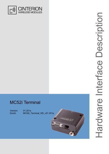
<strong>MC52i</strong> <strong>Terminal</strong><br />
Version: 01.201a<br />
DocId: <strong>MC52i</strong>_<strong>Terminal</strong>_HD_v01.201a<br />
<strong>Hardware</strong> <strong>Interface</strong> <strong>Description</strong>
<strong>MC52i</strong> <strong>Terminal</strong> <strong>Hardware</strong> <strong>Interface</strong> <strong>Description</strong><br />
2<br />
<br />
Document Name:<br />
<strong>MC52i</strong> <strong>Terminal</strong><br />
<strong>Hardware</strong> <strong>Interface</strong> <strong>Description</strong><br />
Version: 01.201a<br />
Date: 2010-04-16<br />
DocId:<br />
Status<br />
<strong>MC52i</strong>_<strong>Terminal</strong>_HD_v01.201a<br />
Confidential / Released<br />
GENERAL NOTE<br />
THE USE OF THE PRODUCT INCLUDING THE SOFTWARE AND DOCUMENTATION (THE "PROD-<br />
UCT") IS SUBJECT TO THE RELEASE NOTE PROVIDED TOGETHER WITH PRODUCT. IN ANY<br />
EVENT THE PROVISIONS OF THE RELEASE NOTE SHALL PREVAIL. THIS DOCUMENT CON-<br />
TAINS INFORMATION ON CINTERION PRODUCTS. THE SPECIFICATIONS IN THIS DOCUMENT<br />
ARE SUBJECT TO CHANGE AT CINTERION'S DISCRETION. CINTERION WIRELESS MODULES<br />
GMBH GRANTS A NON-EXCLUSIVE RIGHT TO USE THE PRODUCT. THE RECIPIENT SHALL NOT<br />
TRANSFER, COPY, MODIFY, TRANSLATE, REVERSE ENGINEER, CREATE DERIVATIVE WORKS;<br />
DISASSEMBLE OR DECOMPILE THE PRODUCT OR OTHERWISE USE THE PRODUCT EXCEPT<br />
AS SPECIFICALLY AUTHORIZED. THE PRODUCT AND THIS DOCUMENT ARE PROVIDED ON AN<br />
"AS IS" BASIS ONLY AND MAY CONTAIN DEFICIENCIES OR INADEQUACIES. TO THE MAXIMUM<br />
EXTENT PERMITTED BY APPLICABLE LAW, CINTERION WIRELESS MODULES GMBH DIS-<br />
CLAIMS ALL WARRANTIES AND LIABILITIES. THE RECIPIENT UNDERTAKES FOR AN UNLIMITED<br />
PERIOD OF TIME TO OBSERVE SECRECY REGARDING ANY INFORMATION AND DATA PRO-<br />
VIDED TO HIM IN THE CONTEXT OF THE DELIVERY OF THE PRODUCT. THIS GENERAL NOTE<br />
SHALL BE GOVERNED AND CONSTRUED ACCORDING TO GERMAN LAW.<br />
Copyright<br />
Transmittal, reproduction, dissemination and/or editing of this document as well as utilization of its contents<br />
and communication thereof to others without express authorization are prohibited. Offenders will<br />
be held liable for payment of damages. All rights created by patent grant or registration of a utility model<br />
or design patent are reserved.<br />
Copyright © 2010, <strong>Cinterion</strong> Wireless Modules GmbH<br />
Trademark notice<br />
Microsoft and Windows are either registered trademarks or trademarks of Microsoft Corporation in the<br />
United States and/or other countries. All other registered trademarks or trademarks mentioned in this<br />
document are property of their respective owners.<br />
<strong>MC52i</strong>_<strong>Terminal</strong>_HD_v01.201a Page 2 of 45 2010-04-16<br />
Confidential / Released
<strong>MC52i</strong> <strong>Terminal</strong> <strong>Hardware</strong> <strong>Interface</strong> <strong>Description</strong><br />
Contents<br />
45<br />
<br />
Contents<br />
0 Document History ...................................................................................................... 7<br />
1 Introduction ................................................................................................................. 8<br />
1.1 Related Documents ........................................................................................... 8<br />
1.2 Terms and Abbreviations ................................................................................... 9<br />
1.3 Regulatory and Type Approval Information ..................................................... 11<br />
1.3.1 Directives and Standards.................................................................... 11<br />
1.3.2 Safety Precautions.............................................................................. 13<br />
2 Product Concept ....................................................................................................... 15<br />
2.1 Key Features at a Glance ................................................................................ 15<br />
3 <strong>Interface</strong> <strong>Description</strong> ................................................................................................ 17<br />
3.1 Overview .......................................................................................................... 17<br />
3.2 Block Diagram.................................................................................................. 18<br />
3.3 Operating Modes ............................................................................................. 19<br />
3.4 <strong>Terminal</strong> Circuit................................................................................................ 20<br />
3.5 Power Supply................................................................................................... 21<br />
3.5.1 Turn <strong>MC52i</strong> <strong>Terminal</strong> on ..................................................................... 22<br />
3.5.2 Reset <strong>MC52i</strong> <strong>Terminal</strong> ........................................................................ 22<br />
3.5.3 Turn <strong>MC52i</strong> <strong>Terminal</strong> off ..................................................................... 22<br />
3.5.4 Disconnecting power supply ............................................................... 23<br />
3.5.5 Automatic thermal shutdown............................................................... 23<br />
3.5.6 RTC..................................................................................................... 23<br />
3.6 RS-232 <strong>Interface</strong>.............................................................................................. 24<br />
3.7 Audio <strong>Interface</strong>................................................................................................. 25<br />
3.7.1 Supported Audio Modes ..................................................................... 26<br />
3.7.2 Speech processing ............................................................................. 27<br />
3.8 SIM <strong>Interface</strong>.................................................................................................... 28<br />
3.9 Status LED....................................................................................................... 29<br />
3.10 Antenna <strong>Interface</strong>............................................................................................. 30<br />
4 Electrical and Environmental Characteristics........................................................ 32<br />
4.1 Absolute Maximum Ratings ............................................................................. 32<br />
4.2 Operating Temperatures.................................................................................. 33<br />
4.3 Storage Conditions .......................................................................................... 34<br />
4.4 Electrical Specifications of the Application <strong>Interface</strong>........................................ 35<br />
4.4.1 On/Off Control..................................................................................... 35<br />
4.4.2 RS-232 <strong>Interface</strong>................................................................................. 36<br />
4.4.3 Audio <strong>Interface</strong>.................................................................................... 37<br />
4.5 Electrical Characteristics of the Voiceband Part .............................................. 38<br />
4.6 Power Supply Ratings...................................................................................... 39<br />
4.7 Antenna <strong>Interface</strong>............................................................................................. 40<br />
<strong>MC52i</strong>_<strong>Terminal</strong>_HD_v01.201a Page 3 of 45 2010-04-16<br />
Confidential / Released
<strong>MC52i</strong> <strong>Terminal</strong> <strong>Hardware</strong> <strong>Interface</strong> <strong>Description</strong><br />
Contents<br />
45<br />
<br />
5 Mechanical Characteristics...................................................................................... 41<br />
5.1 Mounting Example ........................................................................................... 42<br />
6 Full Type Approval.................................................................................................... 43<br />
6.1 <strong>Cinterion</strong> Reference Setup............................................................................... 43<br />
6.2 Restrictions ...................................................................................................... 44<br />
6.3 CE Conformity.................................................................................................. 44<br />
6.4 EMC ................................................................................................................. 44<br />
7 List of Parts and Accessories.................................................................................. 45<br />
<strong>MC52i</strong>_<strong>Terminal</strong>_HD_v01.201a Page 4 of 45 2010-04-16<br />
Confidential / Released
<strong>MC52i</strong> <strong>Terminal</strong> <strong>Hardware</strong> <strong>Interface</strong> <strong>Description</strong><br />
Tables<br />
5<br />
<br />
Tables<br />
Table 1: Terms and abbreviations.................................................................................. 9<br />
Table 2: Directives ....................................................................................................... 11<br />
Table 3: Standards of European type approval............................................................ 11<br />
Table 4: Requirements of quality ................................................................................. 12<br />
Table 5:<br />
Standards of the Ministry of Information Industry of the<br />
People’s Republic of China............................................................................ 12<br />
Table 6: Toxic or hazardous substances or elements with defined concentration limits 12<br />
Table 7: Overview of operating modes ........................................................................ 19<br />
Table 8: Female 6-pole Western plug for power supply, ignition, power down............ 21<br />
Table 9: 9-pole D-Sub (female) RS-232....................................................................... 24<br />
Table 10: Audio modes .................................................................................................. 26<br />
Table 11: Coding of the green status LED..................................................................... 29<br />
Table 12: Absolute maximum ratings............................................................................. 32<br />
Table 13: Operating supply voltage for <strong>MC52i</strong> <strong>Terminal</strong>................................................ 32<br />
Table 14:<br />
Ambient operating temperature of <strong>MC52i</strong> <strong>Terminal</strong> according to<br />
IEC 60068-2 (w/o forced air circulation)......................................................... 33<br />
Table 15: Storage conditions ......................................................................................... 34<br />
Table 16: On/Off control line specifications (requirements) ........................................... 35<br />
Table 17: RS-232 interface specifications (requirements) ............................................. 36<br />
Table 18: Audio interface specifications (requirements) ................................................ 37<br />
Table 19: Audio parameters adjustable by AT commands ............................................ 38<br />
Table 20: Power supply specifications (to be defined)................................................... 39<br />
Table 21: Antenna interface characteristics................................................................... 40<br />
Table 22: Mechanical characteristics............................................................................. 41<br />
Table 23: List of parts and accessories.......................................................................... 45<br />
<strong>MC52i</strong>_<strong>Terminal</strong>_HD_v01.201a Page 5 of 45 2010-04-16<br />
Confidential / Released
<strong>MC52i</strong> <strong>Terminal</strong> <strong>Hardware</strong> <strong>Interface</strong> <strong>Description</strong><br />
Figures<br />
6<br />
<br />
Figures<br />
Figure 1: <strong>MC52i</strong> <strong>Terminal</strong> rear view ............................................................................... 17<br />
Figure 2: Block diagram ................................................................................................. 18<br />
Figure 3: <strong>MC52i</strong> <strong>Terminal</strong> circuit block diagram............................................................. 20<br />
Figure 4: 6-pole Western jack for power supply, ignition, power down .......................... 21<br />
Figure 5: Pin assignment RS-232 (D-Sub 9-pole female).............................................. 24<br />
Figure 6: Audio Western plug (4-pole female)................................................................ 25<br />
Figure 7: Audio block diagram........................................................................................ 25<br />
Figure 8: SIM interface................................................................................................... 28<br />
Figure 9: Status LED...................................................................................................... 29<br />
Figure 10: Antenna interface............................................................................................ 30<br />
Figure 11: Antenna connector circuit on <strong>MC52i</strong> module .................................................. 30<br />
Figure 12: Recommended antenna connector................................................................. 31<br />
Figure 13: Mechanical dimensions................................................................................... 41<br />
Figure 14: Recommended screws.................................................................................... 42<br />
Figure 15: Attaching <strong>MC52i</strong> <strong>Terminal</strong> to a top-hat rail...................................................... 42<br />
Figure 16: Reference equipment for approval.................................................................. 43<br />
<strong>MC52i</strong>_<strong>Terminal</strong>_HD_v01.201a Page 6 of 45 2010-04-16<br />
Confidential / Released
<strong>MC52i</strong> <strong>Terminal</strong> <strong>Hardware</strong> <strong>Interface</strong> <strong>Description</strong><br />
0 Document History<br />
7<br />
<br />
0 Document History<br />
Preceding document: "<strong>MC52i</strong> <strong>Terminal</strong> <strong>Hardware</strong> <strong>Interface</strong> <strong>Description</strong>" Version 01.201<br />
New document: "<strong>MC52i</strong> <strong>Terminal</strong> <strong>Hardware</strong> <strong>Interface</strong> <strong>Description</strong>" Version 01.201a<br />
Chapter What is new<br />
1 Added remark on <strong>MC52i</strong> <strong>Terminal</strong> being the successor of the MC35i <strong>Terminal</strong>.<br />
1.3.1 Revised directives and standards.<br />
2.1 Added temperature and weight information.<br />
3.5 Revised RTC reset timing (see also Table 20).<br />
Revised PD_IN characteristics in Table 8.<br />
3.10 Added remarks regarding antenna installation.<br />
4.2 Removed Table 15.<br />
Added maximum ambient operating temperatures.<br />
4.6 Added power supply ratings to Table 20.<br />
5 Added temperature and weight information to Table 22.<br />
7 Added ordering information for power supply unit.<br />
New document: "<strong>MC52i</strong> <strong>Terminal</strong> <strong>Hardware</strong> <strong>Interface</strong> <strong>Description</strong>" Version 01.201<br />
Chapter What is new<br />
--- Initial document setup.<br />
<strong>MC52i</strong>_<strong>Terminal</strong>_HD_v01.201a Page 7 of 45 2010-04-16<br />
Confidential / Released
<strong>MC52i</strong> <strong>Terminal</strong> <strong>Hardware</strong> <strong>Interface</strong> <strong>Description</strong><br />
1 Introduction<br />
14<br />
<br />
1 Introduction<br />
This document 1 describes the hardware of the <strong>Cinterion</strong> <strong>MC52i</strong> <strong>Terminal</strong> as successor of the<br />
MC35i <strong>Terminal</strong>.<br />
The scope of this document includes interface specifications, electrical issues and mechanical<br />
characteristics of <strong>MC52i</strong> <strong>Terminal</strong>. It specifies standards pertaining to wireless applications and<br />
outlines requirements that must be adhered to for successful product design. The <strong>MC52i</strong> <strong>Terminal</strong><br />
is a compact GSM modem for the transfer of data, voice, SMS and faxes in GSM networks.<br />
Industrial standard interfaces and an integrated SIM card reader allow using <strong>MC52i</strong><br />
<strong>Terminal</strong> easily as a quad band GSM/GPRS terminal.<br />
1.1 Related Documents<br />
[1] <strong>MC52i</strong> <strong>Terminal</strong> AT Command Set<br />
[2] <strong>MC52i</strong> <strong>Terminal</strong> Release Notes<br />
[3] Application Note 16: Upgrading Firmware<br />
[4] Application Note 24: Application Developer’s Guide<br />
[5] Multiplexer User's Guide<br />
[6] Multiplex Driver Developer’s Guide<br />
[7] Multiplexer Driver Installation Guide<br />
Prior to using the GSM terminal read the latest product information provided in the Release<br />
Notes.<br />
You can use the following link to visit the <strong>Cinterion</strong> Website:<br />
http://www.cinterion.com<br />
1.<br />
The document is effective only if listed in the appropriate Release Notes as part of the technical documentation<br />
delivered with your <strong>Cinterion</strong> wireless product.<br />
<strong>MC52i</strong>_<strong>Terminal</strong>_HD_v01.201a Page 8 of 45 2010-04-16<br />
Confidential / Released
<strong>MC52i</strong> <strong>Terminal</strong> <strong>Hardware</strong> <strong>Interface</strong> <strong>Description</strong><br />
1.2 Terms and Abbreviations<br />
14<br />
<br />
1.2 Terms and Abbreviations<br />
Table 1: Terms and abbreviations<br />
Abbreviation <strong>Description</strong><br />
ADC<br />
Analog-to-Digital Converter<br />
ARP<br />
Antenna Reference Point<br />
ASIC<br />
Application Specific Integrated Circuit<br />
ATC<br />
AT Cellular<br />
BTS<br />
Base Transceiver Station<br />
CB<br />
Cell Broadcast<br />
CODEC Coder-Decoder<br />
CPU<br />
Central Processing Unit<br />
DCE<br />
Data Circuit terminating Equipment<br />
DSP<br />
Digital Signal Processor<br />
DSR<br />
Data Set Ready<br />
DTR<br />
Data <strong>Terminal</strong> Ready<br />
EFR<br />
Enhanced Full Rate<br />
EGSM Enhanced GSM<br />
EMC<br />
Electromagnetic Compatibility<br />
ESD<br />
Electrostatic Discharge<br />
ETS<br />
European Telecommunication Standard<br />
FDMA Frequency Division Multiple Access<br />
FR<br />
Full rate<br />
G.C.F. GSM Conformity Forum<br />
GSM<br />
Global Standard for Mobile Communication<br />
HF<br />
Hands-free<br />
HR<br />
Half rate<br />
HW<br />
<strong>Hardware</strong><br />
IC<br />
Integrated Circuit<br />
IF<br />
Intermediate Frequency<br />
IMEI<br />
International Mobile Equipment Identifier<br />
I/O<br />
Input/ Output<br />
IGT<br />
Ignition<br />
ISO<br />
International Standards Organization<br />
ITU<br />
International Telecommunications Union<br />
kbps<br />
kbits per second<br />
Li-Ion Lithium-Ion<br />
<strong>MC52i</strong>_<strong>Terminal</strong>_HD_v01.201a Page 9 of 45 2010-04-16<br />
Confidential / Released
<strong>MC52i</strong> <strong>Terminal</strong> <strong>Hardware</strong> <strong>Interface</strong> <strong>Description</strong><br />
1.2 Terms and Abbreviations<br />
14<br />
<br />
Table 1: Terms and abbreviations<br />
Abbreviation <strong>Description</strong><br />
LVD<br />
Low voltage Directive<br />
Mbps Mbits per second<br />
MMI<br />
Machine Machine <strong>Interface</strong><br />
MO<br />
Mobile Originated<br />
MS<br />
Mobile Station<br />
MT<br />
Mobile Terminated<br />
NC<br />
Not Connected<br />
NTC<br />
Negative Temperature Coefficient<br />
PA<br />
Power Amplifier<br />
PCB<br />
Printed Circuit Board<br />
PCM<br />
Pulse Code Modulation<br />
PCS<br />
Personal Communication System<br />
PD<br />
Power Down<br />
PDU<br />
Protocol Data Unit<br />
R&TTE Radio and Telecommunication <strong>Terminal</strong> Equipment<br />
RAM<br />
Random Access Memory<br />
RF<br />
Radio frequency<br />
RI<br />
Ring Indication<br />
ROM<br />
Read Only Memory<br />
RX<br />
Receive direction<br />
SIM<br />
Subscriber Identification Module<br />
SMS<br />
Short Message Service<br />
SRAM Static Random Access Memory<br />
SW<br />
Software<br />
TDD<br />
Time Division Duplex<br />
TDMA Time Division Multiple Access<br />
TX<br />
Transmit direction<br />
UART Universal Asynchronous Receiver and Transmitter<br />
VAD<br />
Voice Activity Detection<br />
ZIF<br />
Zero Insertion Force<br />
<strong>MC52i</strong>_<strong>Terminal</strong>_HD_v01.201a Page 10 of 45 2010-04-16<br />
Confidential / Released
<strong>MC52i</strong> <strong>Terminal</strong> <strong>Hardware</strong> <strong>Interface</strong> <strong>Description</strong><br />
1.3 Regulatory and Type Approval Information<br />
14<br />
<br />
1.3 Regulatory and Type Approval Information<br />
1.3.1 Directives and Standards<br />
<strong>MC52i</strong> <strong>Terminal</strong> has been designed to comply with the directives and standards listed below.<br />
Table 2: Directives<br />
99/05/EC Directive of the European Parliament and of the council of 9 March 1999<br />
on radio equipment and telecommunications terminal equipment and the<br />
mutual recognition of their conformity (in short referred to as R&TTE Directive<br />
1999/5/EC).<br />
The product is labeled with the CE conformity mark<br />
2002/95/EC<br />
Directive of the European Parliament and of the Council of<br />
27 January 2003 on the restriction of the use of certain<br />
hazardous substances in electrical and electronic equipment<br />
(RoHS)<br />
2002/96/EC<br />
2003/108/EC<br />
72/245/EC<br />
2004/104/EC<br />
Directive of the European Parliament and of the Council on waste electrical<br />
and electronic equipment (WEEE)<br />
Directive of the European Parliament and of the Council of 8 December<br />
2003 amending directive 2002/96/ec on waste electrical and electronic<br />
equipment (WEEE)<br />
Automotive EMC Directive.<br />
Automotive EMC Directive.<br />
Table 3: Standards of European type approval<br />
3GPP TS 51.010-1<br />
ETSI EN 301 511 V9.0.2<br />
GCF-CC V3.27.1<br />
ETSI EN 301 489-1<br />
V1.8.1<br />
ETSI EN 301 489-7<br />
V1.3.1<br />
EN 62311-2008<br />
EN 60950-1 (2006)<br />
“Digital cellular telecommunications system (Phase 2); Mobile Station<br />
(MS) conformance specification”<br />
Candidate Harmonized European Standard (Telecommunications series)<br />
Global System for Mobile communications (GSM); Harmonized standard<br />
for mobile stations in the GSM 900 and DCS 1800 bands covering essential<br />
requirements under article 3.2 of the R&TTE directive (1999/5/EC)<br />
(GSM 13.11 version 7.0.1 Release 1998)<br />
Global Certification Forum - Certification Criteria<br />
Candidate Harmonized European Standard (Telecommunications series)<br />
Electro Magnetic Compatibility and Radio spectrum Matters (ERM); Electro<br />
Magnetic Compatibility (EMC) standard for radio equipment and services;<br />
Part 1: Common Technical Requirements<br />
Candidate Harmonized European Standard (Telecommunications series)<br />
Electro Magnetic Compatibility and Radio spectrum Matters (ERM); Electro<br />
Magnetic Compatibility (EMC) standard for radio equipment and services;<br />
Part 7: Specific conditions for mobile and portable radio and<br />
ancillary equipment of digital cellular radio telecommunications systems<br />
(GSM and DCS)<br />
Assessment of electronic and electrical equipment related to human exposure<br />
restrictions for electromagnetic fields (0 Hz - 300 GHz)<br />
Safety of information technology equipment<br />
<strong>MC52i</strong>_<strong>Terminal</strong>_HD_v01.201a Page 11 of 45 2010-04-16<br />
Confidential / Released
<strong>MC52i</strong> <strong>Terminal</strong> <strong>Hardware</strong> <strong>Interface</strong> <strong>Description</strong><br />
1.3 Regulatory and Type Approval Information<br />
14<br />
<br />
Table 4: Requirements of quality<br />
IEC 60068<br />
Environmental testing<br />
DIN EN 60529<br />
IP codes<br />
Table 5: Standards of the Ministry of Information Industry of the People’s Republic of China<br />
SJ/T 11363-2006<br />
SJ/T 11364-2006<br />
“Requirements for Concentration Limits for Certain Hazardous Substances<br />
in Electronic Information Products” (2006-06).<br />
“Marking for Control of Pollution Caused by Electronic<br />
Information Products” (2006-06).<br />
According to the “Chinese Administration on the Control<br />
of Pollution caused by Electronic Information Products”<br />
(ACPEIP) the EPUP, i.e., Environmental Protection Use<br />
Period, of this product is 20 years as per the symbol<br />
shown here, unless otherwise marked. The EPUP is valid only as long as<br />
the product is operated within the operating limits described in the <strong>Hardware</strong><br />
<strong>Interface</strong> <strong>Description</strong>.<br />
Please see Table 1.3.2 for an overview of toxic or hazardous substances<br />
or elements that might be contained in product parts in concentrations<br />
above the limits defined by SJ/T 11363-2006.<br />
Table 6: Toxic or hazardous substances or elements with defined concentration limits<br />
<strong>MC52i</strong>_<strong>Terminal</strong>_HD_v01.201a Page 12 of 45 2010-04-16<br />
Confidential / Released
<strong>MC52i</strong> <strong>Terminal</strong> <strong>Hardware</strong> <strong>Interface</strong> <strong>Description</strong><br />
1.3 Regulatory and Type Approval Information<br />
14<br />
<br />
1.3.2 Safety Precautions<br />
The following safety precautions must be observed during all phases of the operation, usage,<br />
service or repair of any cellular terminal or mobile incorporating <strong>MC52i</strong> <strong>Terminal</strong>. Manufacturers<br />
of the cellular terminal are advised to convey the following safety information to users and<br />
operating personnel and incorporate these guidelines into all manuals supplied with the product.<br />
Failure to comply with these precautions violates safety standards of design, manufacture<br />
and intended use of the product. <strong>Cinterion</strong> Wireless Modules GmbH assumes no liability for<br />
customer’s failure to comply with these precautions.<br />
When in hospitals or other health care facilities, observe the restrictions on the use<br />
of mobiles. Switch off the cellular terminal or mobile if to be instructed to do so by<br />
the guidelines posted in sensitive areas. Medical equipment may be sensitive to RF<br />
energy.<br />
The operation of cardiac pacemakers, other implanted medical equipment and<br />
hearing aids can be affected by interference from cellular terminals or mobiles<br />
placed close to the device. If in doubt about potential danger, contact the physician<br />
or the manufacturer of the device to verify that the equipment is properly shielded.<br />
Pacemaker patients are advised to keep their hand-held mobile away from the<br />
pacemaker, while it is on. This personal subgroup always should check the distance<br />
to the mobile.<br />
Switch off the cellular terminal or mobile before boarding an aircraft. Make sure it<br />
cannot be switched on inadvertently. The operation of wireless appliances in an aircraft<br />
is forbidden to prevent interference with communications systems. Failure to<br />
observe these instructions may lead to the suspension or denial of cellular services<br />
to the offender, legal action, or both.<br />
Check the local and actual laws about these themes.<br />
Do not operate the cellular terminal or mobile in the presence of flammable gases<br />
or fumes. Switch off the cellular terminal when you are near petrol stations, fuel<br />
depots, chemical plants or where blasting operations are in progress. Operation of<br />
any electrical equipment in potentially explosive atmospheres can constitute a<br />
safety hazard.<br />
Your cellular terminal or mobile receives and transmits radio frequency energy while<br />
switched on. Remember that interference can occur if it is used close to TV sets,<br />
radios, computers or inadequately shielded equipment. Follow any special regulations<br />
and always switch off the cellular terminal or mobile wherever forbidden, or<br />
when you suspect that it may cause interference or danger.<br />
Road safety comes first! Do not use a hand-held cellular terminal or mobile while<br />
driving a vehicle unless it is securely mounted in a holder for speakerphone operation.<br />
Before making a call with a hand-held terminal or mobile park the vehicle.<br />
Speakerphones must be installed by qualified personnel. Faulty installation or operation<br />
can constitute a safety hazard.<br />
Check the actual and local laws about these themes.<br />
<strong>MC52i</strong>_<strong>Terminal</strong>_HD_v01.201a Page 13 of 45 2010-04-16<br />
Confidential / Released
<strong>MC52i</strong> <strong>Terminal</strong> <strong>Hardware</strong> <strong>Interface</strong> <strong>Description</strong><br />
1.3 Regulatory and Type Approval Information<br />
14<br />
<br />
IMPORTANT!<br />
Cellular terminals or mobiles operate using radio signals and cellular networks. In<br />
that case connections cannot be guaranteed at all times under all conditions. Therefore,<br />
you should never rely solely upon any wireless device for essential communications,<br />
for example emergency calls.<br />
Remember, in order to make calls or receive calls the cellular terminal or mobile<br />
must be switched on in a service area with adequate cellular signal strength.<br />
Some networks do not allow for emergency calls if certain network services or<br />
phone features are in use (e.g. lock functions, fixed dialing etc.). You may need to<br />
deactivate those features before you can make an emergency call.<br />
Some networks require a valid SIM card to be properly inserted in the cellular terminal<br />
or mobile.<br />
If a power supply unit is used to supply the device it must meet the demands placed<br />
on SELV circuits in accordance with EN60950. The maximum permissible connection<br />
length between the device and the supply source should not exceed 3m.<br />
According to the guidelines for human exposure to radio frequency energy, an<br />
antenna connected to the FME jack of the device should be placed at least 20cm<br />
away from human bodies.<br />
<strong>MC52i</strong>_<strong>Terminal</strong>_HD_v01.201a Page 14 of 45 2010-04-16<br />
Confidential / Released
<strong>MC52i</strong> <strong>Terminal</strong> <strong>Hardware</strong> <strong>Interface</strong> <strong>Description</strong><br />
2 Product Concept<br />
16<br />
<br />
2 Product Concept<br />
2.1 Key Features at a Glance<br />
Feature<br />
General<br />
Incorporates <strong>MC52i</strong><br />
module<br />
Frequency bands<br />
GSM class<br />
Output power (according<br />
to Release 99, V5)<br />
Power supply<br />
Ambient operating temperature<br />
according to<br />
IEC 60068-2<br />
Physical<br />
RoHS, WEEE<br />
Implementation<br />
The <strong>MC52i</strong> module handles all processing for audio, signal and data within<br />
the <strong>MC52i</strong> <strong>Terminal</strong>. Internal software runs the application interface and the<br />
whole GSM protocol stack.<br />
Dual band: GSM 900/1800MHz<br />
Small MS<br />
Class 4 (+33dBm ±2dB) for EGSM900<br />
Class 1 (+30dBm ±2dB) for GSM1800<br />
The values stated above are maximum limits. According to Release 99, the<br />
maximum output power in a multislot configuration may be lower. The nominal<br />
reduction of maximum output power varies with the number of uplink<br />
timeslots used and amounts to 3.0dB for 2Tx.<br />
Single supply voltage 8V to 30V<br />
Normal operation: -20°C to +65°C<br />
Restricted operation: -30°C to -20°C and +65°C to +75°C<br />
Dimensions: 65mm x 74mm x 33mm (approx.)<br />
Weight: 110g (approx.)<br />
All hardware components are fully compliant with the EU RoHS and WEEE<br />
Directives<br />
GSM / GPRS features<br />
Data transfer<br />
GPRS:<br />
• Multislot Class 8<br />
• Full PBCCH support<br />
• Mobile Station Class B<br />
• Coding Scheme 1 – 4<br />
CSD:<br />
• V.110, RLP, non-transparent<br />
• 2.4, 4.8, 9.6, 14.4kbps<br />
• USSD<br />
PPP-stack for GPRS data transfer<br />
SMS • Point-to-point MT and MO<br />
• Cell broadcast<br />
• Text and PDU mode<br />
• Storage: SIM card plus 25 SMS locations in mobile equipment<br />
• Transmission of SMS alternatively over CSD or GPRS. Preferred mode<br />
can be user defined.<br />
Fax Group 3; Class 2 and Class 1<br />
<strong>MC52i</strong>_<strong>Terminal</strong>_HD_v01.201a Page 15 of 45 2010-04-16<br />
Confidential / Released
<strong>MC52i</strong> <strong>Terminal</strong> <strong>Hardware</strong> <strong>Interface</strong> <strong>Description</strong><br />
2.1 Key Features at a Glance<br />
16<br />
<br />
Feature<br />
Audio<br />
Implementation<br />
Speech codecs:<br />
• Half rate HR (ETS 06.20)<br />
• Full rate FR (ETS 06.10)<br />
• Enhanced full rate EFR (ETS 06.50/06.60/06.80)<br />
• Adaptive Multi Rate AMR<br />
Echo cancellation, DTMF, 7 ringing tones<br />
Software<br />
AT commands<br />
Firmware update<br />
Hayes 3GPP TS 27.007, TS 27.005, <strong>Cinterion</strong><br />
Upgradeable via serial interface.<br />
<strong>Interface</strong>s<br />
Serial interface • RS-232 interface, bi-directional bus for AT commands and data.<br />
• Multiplex ability according to GSM 07.10 Multiplexer protocol<br />
• Baud rates from 300bps to 115200bps<br />
• Autobauding supports: 1200, 2400, 4800, 9600, 19200, 38.400, 57600<br />
and 115200bps<br />
• Supports RTS/CTS hardware handshake and software XON/XOFF<br />
flow control<br />
Audio<br />
Analog (Microphone, Earpiece)<br />
SIM card reader Supported SIM cards: 3V, 1.8V<br />
Antenna<br />
Connected via antenna FME connector<br />
Power on/off, Reset<br />
Power on<br />
DTR line at RS232 interface or IGT_IN line at power connector<br />
Power off • Normal switch-off by AT^SMSO or On/Off push button<br />
• Emergency switch-off via EMERGOFF line at power connector<br />
• Automatic switch-off in case of critical temperature and voltage conditions<br />
Reset<br />
Orderly shutdown and reset by AT command or power down signal.<br />
Special features<br />
Real time clock<br />
Phonebook<br />
Timer functions via AT commands<br />
SIM card and phone<br />
<strong>MC52i</strong>_<strong>Terminal</strong>_HD_v01.201a Page 16 of 45 2010-04-16<br />
Confidential / Released
<strong>MC52i</strong> <strong>Terminal</strong> <strong>Hardware</strong> <strong>Interface</strong> <strong>Description</strong><br />
3 <strong>Interface</strong> <strong>Description</strong><br />
31<br />
<br />
3 <strong>Interface</strong> <strong>Description</strong><br />
3.1 Overview<br />
<strong>MC52i</strong> <strong>Terminal</strong> provides the following connectors for power supply, interface and antenna:<br />
• 6-pole Western plug (female) for power supply, ignition, power down signal<br />
• 4-pole Western plug (female) for audio accessory, such as a handset<br />
• 9-pole (female) SUB-D plug for RS-232 serial interface<br />
• FME Jack (male) for antenna (Antenna interface)<br />
• SIM card holder<br />
Status LED<br />
Power supply<br />
Audio interface<br />
SIM card holder<br />
RS-232 interface<br />
Antenna interface<br />
Figure 1: <strong>MC52i</strong> <strong>Terminal</strong> rear view<br />
<strong>MC52i</strong>_<strong>Terminal</strong>_HD_v01.201a Page 17 of 45 2010-04-16<br />
Confidential / Released
<strong>MC52i</strong> <strong>Terminal</strong> <strong>Hardware</strong> <strong>Interface</strong> <strong>Description</strong><br />
3.2 Block Diagram<br />
31<br />
<br />
3.2 Block Diagram<br />
Figure 2 shows a block diagram of a sample configuration that incorporates an <strong>MC52i</strong> <strong>Terminal</strong><br />
and typical accessories.<br />
Antenna reference point<br />
(ARP)<br />
Antenna interface<br />
Antenna<br />
MC5xi Module<br />
B2B connector<br />
Adapter board<br />
Flex cable<br />
LED<br />
<strong>Terminal</strong><br />
circuit<br />
SIM card<br />
interface<br />
RS-232<br />
interface<br />
Power supply<br />
Audio interface<br />
on/off<br />
IGT_IN<br />
PD_IN<br />
Fuse<br />
Handset<br />
Host<br />
controller<br />
Power<br />
supply<br />
Data<br />
sink/<br />
source<br />
External<br />
application<br />
MC5xi <strong>Terminal</strong><br />
Figure 2: Block diagram<br />
<strong>MC52i</strong>_<strong>Terminal</strong>_HD_v01.201a Page 18 of 45 2010-04-16<br />
Confidential / Released
<strong>MC52i</strong> <strong>Terminal</strong> <strong>Hardware</strong> <strong>Interface</strong> <strong>Description</strong><br />
3.3 Operating Modes<br />
31<br />
<br />
3.3 Operating Modes<br />
The table below briefly summarizes the various operating modes referred to in the following<br />
chapters.<br />
Table 7: Overview of operating modes<br />
Normal operation GSM / GPRS SLEEP Various power save modes set with AT+CFUN command.<br />
Software is active to minimum extent. If the <strong>Terminal</strong> was<br />
registered to the GSM network in IDLE mode, it is registered<br />
and paging with the BTS in SLEEP mode, too.<br />
Power saving can be chosen at different levels: The<br />
NON-CYCLIC SLEEP mode (AT+CFUN=0) disables the<br />
AT interface. The CYCLIC SLEEP modes AT+CFUN=7<br />
and 9 alternatingly activate and deactivate the AT interfaces<br />
to allow permanent access to all AT commands.<br />
GSM IDLE<br />
Software is active. Once registered to the GSM network<br />
paging with BTS is carried out. The <strong>Terminal</strong> is ready to<br />
send and receive.<br />
GSM TALK<br />
Connection between two subscribers is in progress.<br />
Power consumption depends on network coverage individual<br />
settings, such as DTX off/on, FR/EFR/HR, hopping<br />
sequences, antenna.<br />
GPRS IDLE<br />
<strong>Terminal</strong> is ready for GPRS data transfer, but no data is<br />
currently sent or received. Power consumption depends<br />
on network settings and GPRS configuration (e.g. multislot<br />
settings).<br />
GPRS DATA GPRS data transfer in progress. Power consumption<br />
depends on network settings (e.g. power control level),<br />
uplink / downlink data rates, GPRS configuration (e.g.<br />
used multislot settings) and reduction of maximum output<br />
power.<br />
POWER DOWN<br />
Normal shutdown after sending the AT^SMSO command or after activation of the<br />
PD_IN line.<br />
The RTC works continuously, but the software is not active. <strong>Interface</strong>s are not<br />
accessible.<br />
<strong>MC52i</strong>_<strong>Terminal</strong>_HD_v01.201a Page 19 of 45 2010-04-16<br />
Confidential / Released
Board-to-board connector<br />
Western jack 6 pin<br />
Power Supply<br />
Flex cable<br />
EMC (on/off)<br />
Module adapter<br />
EMC<br />
(Audio)<br />
Western<br />
4 pin<br />
Audio<br />
RS232 Treiber<br />
D-Sub<br />
9-pin<br />
RS232<br />
<strong>Interface</strong>.<br />
GSM/GPRS<br />
status<br />
<strong>MC52i</strong> <strong>Terminal</strong> <strong>Hardware</strong> <strong>Interface</strong> <strong>Description</strong><br />
3.4 <strong>Terminal</strong> Circuit<br />
31<br />
<br />
3.4 <strong>Terminal</strong> Circuit<br />
SIM<br />
Card<br />
<strong>Interface</strong><br />
SIM<br />
CCxxx<br />
6<br />
LED<br />
LED driver<br />
BATT+<br />
DC<br />
DC<br />
Lin . Reg.<br />
VMIC<br />
SYNC<br />
VDD<br />
5V<br />
/ RXD0,/ TXD0,/ RTS0,/ CTS0,/ DTR0,/ DSR0,/ DCD0,/ RING0<br />
VDD<br />
EMC<br />
8<br />
RS 232 interface<br />
EPN, EPP<br />
MICN, MICP<br />
GSM Module<br />
DTR<br />
VPP<br />
VDD<br />
VDD<br />
Microphone<br />
supply<br />
VMIC<br />
Audio<br />
PD_IN<br />
(Power Down)<br />
/ IGT (Ignition)<br />
/EMERGOFF<br />
(Power Down)<br />
Power on/ of<br />
f<br />
Power on/off<br />
logic<br />
VPP<br />
IGT_IN<br />
(Ignition)<br />
ON/ OFF logic<br />
BATT+<br />
(Main supply)<br />
Regulator<br />
Overvoltage<br />
protection<br />
Fuse<br />
EMC<br />
( Power)<br />
VPLUS<br />
(Power)<br />
VDD<br />
VDDLP<br />
(Power down supply)<br />
EN<br />
Voltage<br />
limiter<br />
Power supply<br />
VDD<br />
<strong>Terminal</strong> circuit<br />
Antenna <strong>Interface</strong><br />
RF cable<br />
U.FL-R-SMT (Antenna reference point)<br />
Antenna interface<br />
FME 50 Ohm<br />
Figure 3: <strong>MC52i</strong> <strong>Terminal</strong> circuit block diagram<br />
<strong>MC52i</strong>_<strong>Terminal</strong>_HD_v01.201a Page 20 of 45 2010-04-16<br />
Confidential / Released
<strong>MC52i</strong> <strong>Terminal</strong> <strong>Hardware</strong> <strong>Interface</strong> <strong>Description</strong><br />
3.5 Power Supply<br />
31<br />
<br />
3.5 Power Supply<br />
The power supply of the <strong>MC52i</strong> <strong>Terminal</strong> has to be a single voltage source of V PLUS =8V…30V<br />
capable of providing a peak current (pulsed 2x577ms at T=4.615ms) of about 1.2A at 12V during<br />
an active transmission. The uplink burst causes strong ripple (drop) on the power lines. The<br />
drop voltage should not exceed 1V, but the absolute minimum voltage during drops must be<br />
>7.6V.<br />
The <strong>MC52i</strong> <strong>Terminal</strong> is protected from supply voltage reversal and overvoltage. An internal fuse<br />
that is not removable is intended for electrical safety according to EN60950. An external fast<br />
acting fuse >0.4A with melting integral I 2 t (0.15 … 0.25)A 2 s is necessary to use the <strong>MC52i</strong> <strong>Terminal</strong><br />
at a 12V or 24V power supply system for vehicles.<br />
The power supply must be compliant with the EN60950 guidelines.<br />
A switching regulator regulates the input voltage for the internal supply. In POWER DOWN<br />
mode the switching regulator is turned off by the On/Off logic. A separate voltage regulator supplies<br />
the real time clock (RTC) in the GSM engine.<br />
When power fails for >1ms, <strong>MC52i</strong> <strong>Terminal</strong> resets or switches off. When power fails for >15s<br />
the RTC will be reset.<br />
Table 8: Female 6-pole Western plug for power supply, ignition, power down<br />
Pin Signal name Use Parameters<br />
1 PLUS Power supply 8V – 30V DC, max. 33V for 1 min<br />
2 free --- ---<br />
3 PD_IN Signal for POWER DOWN mode U IH > 5V for t>100ms turns the terminal off.<br />
U IL 5V<br />
Ignition >5V for more than 200ms switches<br />
the <strong>MC52i</strong> <strong>Terminal</strong> on. Ignition is activated<br />
only by a rising edge. The rise time is<br />
<strong>MC52i</strong> <strong>Terminal</strong> <strong>Hardware</strong> <strong>Interface</strong> <strong>Description</strong><br />
3.5 Power Supply<br />
31<br />
<br />
3.5.1 Turn <strong>MC52i</strong> <strong>Terminal</strong> on<br />
The IGT_IN signal (pin 4) switches the <strong>MC52i</strong> <strong>Terminal</strong> on. After start-up, the <strong>MC52i</strong> <strong>Terminal</strong><br />
enters the net searching state. The IGT_IN signal is activated when an appropriate power supply<br />
unit is plugged to the 6-pole Western jack.<br />
While the PD_IN pin (pin3) is not active (voltage 5V to the PD_IN pin (pin 3) for more than 100ms.<br />
The PD_IN signal switches the <strong>MC52i</strong> <strong>Terminal</strong> off. All internal supply voltages are off,<br />
except for the power down voltage, which still feeds the real-time clock (RTC).<br />
Caution: Use the PD_IN pin only when, due to serious problems, the software is not<br />
responding for more than 5 seconds. Pulling the /PD pin causes the loss of all information<br />
stored in the volatile memory since power is cut off immediately. Therefore, this procedure<br />
is intended only for use in case of emergency, e.g. if <strong>MC52i</strong> <strong>Terminal</strong> fails to shut down<br />
properly.<br />
<strong>MC52i</strong>_<strong>Terminal</strong>_HD_v01.201a Page 22 of 45 2010-04-16<br />
Confidential / Released
<strong>MC52i</strong> <strong>Terminal</strong> <strong>Hardware</strong> <strong>Interface</strong> <strong>Description</strong><br />
3.5 Power Supply<br />
31<br />
<br />
When the <strong>MC52i</strong> <strong>Terminal</strong> enters the POWER DOWN mode, e.g. after you have issued the<br />
AT^SMSO command or activated the PD_IN signal, all RS-232 interface lines are active for a<br />
period of 50ms to max. 3.5s. This may cause undefined characters to be transmitted on the<br />
RS-232 lines which can be ignored.<br />
3.5.4 Disconnecting power supply<br />
Before disconnecting the power supply from the PLUS pin, make sure that the <strong>MC52i</strong> <strong>Terminal</strong><br />
is in a safe condition. The best way is to wait 1s after the "^SHUTDOWN" result code has been<br />
indicated.<br />
3.5.5 Automatic thermal shutdown<br />
An on-board NTC measures the temperature of the built-in <strong>MC52i</strong> module. If over- or undertemperature<br />
is detected on the module the <strong>MC52i</strong> <strong>Terminal</strong> automatically shuts down to avoid<br />
thermal damage to the system. Table 14 specifies the ambient temperature threshold for the<br />
<strong>MC52i</strong> <strong>Terminal</strong>.<br />
The automatic shutdown procedure is equivalent to the power-down initiated with the AT^SM-<br />
SO command, i.e. <strong>MC52i</strong> <strong>Terminal</strong> logs off from the network and the software enters a secure<br />
state avoiding loss of data. In IDLE mode it takes typically one minute to deregister from the<br />
network and to switch off.<br />
Alert messages transmitted before the <strong>MC52i</strong> <strong>Terminal</strong> switches off are implemented as Unsolicited<br />
Result codes (URCs). For details see the description of AT^SCTM command provided<br />
in [1].<br />
Thermal shutdown will be deferred if a critical temperature limit is exceeded, while an emergency<br />
call or a call to a predefined phone number is in progress, or during a two minute guard<br />
period after power up. See [1] for details.<br />
3.5.6 RTC<br />
The internal Real Time Clock (RTC) of the <strong>MC52i</strong> <strong>Terminal</strong> retains the time and date and handles<br />
the alarm (reminder) function. The AT+CCLK command serves to set the time and date,<br />
and AT+CALA specifies a reminder message. See [1] for details.<br />
A dedicated voltage regulator backs up the RTC even in POWER DOWN mode and enables<br />
<strong>MC52i</strong> <strong>Terminal</strong> to keep track of time and date.<br />
However, please note that the Alarm mode described in [1], Section AT+CALA, is not intended<br />
for the <strong>MC52i</strong> <strong>Terminal</strong>. The AT+CALA command can only be used to set a reminder message,<br />
but not to configure the mobile to wake up from POWER DOWN mode into Alarm mode. Therefore,<br />
after setting a timer with AT+CALA be sure not to shut down the <strong>MC52i</strong> <strong>Terminal</strong> by<br />
AT^SMSO or PD_IN signal.<br />
<strong>MC52i</strong>_<strong>Terminal</strong>_HD_v01.201a Page 23 of 45 2010-04-16<br />
Confidential / Released
<strong>MC52i</strong> <strong>Terminal</strong> <strong>Hardware</strong> <strong>Interface</strong> <strong>Description</strong><br />
3.6 RS-232 <strong>Interface</strong><br />
31<br />
<br />
3.6 RS-232 <strong>Interface</strong><br />
Via RS-232 interface, the host controller controls the <strong>MC52i</strong> <strong>Terminal</strong> and transports data.<br />
5 4 3 2 1<br />
6<br />
9 8 7<br />
Figure 5: Pin assignment RS-232 (D-Sub 9-pole female)<br />
Table 9: 9-pole D-Sub (female) RS-232<br />
Pin no. Signal name I/O Function<br />
1 /DCD O Data Carrier Detected<br />
2 /RXD O Receive Data<br />
3 /TXD I Transmit Data<br />
4 /DTR I Data <strong>Terminal</strong> Ready<br />
Attention: The ignition of <strong>MC52i</strong> <strong>Terminal</strong> is activated via a rising<br />
edge of high potential (+3 ... +15 V)<br />
5 GND - Ground<br />
6 /DSR O Data Set Ready<br />
7 /RTS I Request To Send<br />
8 /CTS O Clear To Send<br />
9 /RING O Ring Indication<br />
<strong>MC52i</strong> <strong>Terminal</strong> is designed for use as a DCE. Based on the conventions for DCE-DTE connections<br />
it communicates with the customer application (DTE) using the following signals:<br />
• Port TxD @ application sends data to TXD of <strong>MC52i</strong> <strong>Terminal</strong><br />
• Port RxD @ application receives data from RXD of <strong>MC52i</strong> <strong>Terminal</strong><br />
The RS-232 interface is implemented as a serial asynchronous transmitter and receiver conforming<br />
to ITU-T V.24 Interchange Circuits DCE. It is configured for 8 data bits, no parity and<br />
1 stop bit, and can be operated at bit rates from 300bps to 115kbps. Autobauding supports bit<br />
rates from 1.2kbps to 115kbps. <strong>Hardware</strong> handshake using the /RTS and /CTS signals and<br />
XON/XOFF software flow control are supported.<br />
In addition, the modem control signals /DTR, /DSR, /DCD and /RING are available. The modem<br />
control signal RING (Ring Indication) can be used to indicate, to the cellular device application,<br />
that a call or Unsolicited Result Code (URC) is received. There are different modes of operation,<br />
which can be set with AT commands.<br />
Note: The /DTR signal will only be polled once per second from the internal firmware of <strong>MC52i</strong>.<br />
<strong>MC52i</strong>_<strong>Terminal</strong>_HD_v01.201a Page 24 of 45 2010-04-16<br />
Confidential / Released
<strong>MC52i</strong> <strong>Terminal</strong> <strong>Hardware</strong> <strong>Interface</strong> <strong>Description</strong><br />
3.7 Audio <strong>Interface</strong><br />
31<br />
<br />
3.7 Audio <strong>Interface</strong><br />
The audio interface provides an analog input for a microphone and an analog output for an earpiece.<br />
• The microphone input and the earpiece output are balanced.<br />
• For electret microphones a supply source is implemented.<br />
• The microphone supply characteristics are optimized for the recommended Votronic handset.<br />
This handset has been used as the reference handset for type approval (see Chapter<br />
6). An extra approval must be obtained for integrating other handsets or amplifiers.<br />
The amplification of sending direction, receiving direction and sidetone depend on the current<br />
audio mode.<br />
EMC immunity complies with the vehicular environment requirements according to<br />
EN 301 489-7.<br />
2 3<br />
1 4<br />
Pin assignment:<br />
1 MICN (Microphone - )<br />
2 EPN (Earpiece)<br />
3 EPP (Earpiece)<br />
4 MICP (Microphone + )<br />
Figure 6: Audio Western plug (4-pole female)<br />
5.9V<br />
MICP<br />
MICN<br />
4k7<br />
4k7<br />
Ri=9k<br />
+0...42dB in<br />
6dB - steps<br />
(inBbcGain )<br />
A<br />
D<br />
(inCalibrate)<br />
- ...0dB<br />
8<br />
speechcoder<br />
(sideTone)<br />
EPP<br />
EPN<br />
6R8<br />
6R8<br />
0dB;-6dB;-12dB;-18dB<br />
(outBbcGain )<br />
A<br />
D<br />
+<br />
speechdecoder<br />
( outCalibrate[n])<br />
n=0...4<br />
( ) AT parameter<br />
Figure 7: Audio block diagram<br />
<strong>MC52i</strong>_<strong>Terminal</strong>_HD_v01.201a Page 25 of 45 2010-04-16<br />
Confidential / Released
<strong>MC52i</strong> <strong>Terminal</strong> <strong>Hardware</strong> <strong>Interface</strong> <strong>Description</strong><br />
3.7 Audio <strong>Interface</strong><br />
31<br />
<br />
3.7.1 Supported Audio Modes<br />
The audio interface can be configured by AT commands. Refer to [1] for details.<br />
The electrical characteristics of the voiceband part vary with the audio mode. Specifications are<br />
listed in Table 19. To suit several types of audio equipment, three audio modes given by default<br />
can be selected by the AT command AT^SNFS.<br />
Regarding audio performance, compliance with the TS 51010-1 specification and GCF recommendations<br />
has been certified for the parameters provided by audio mode 1 and audio<br />
interface 1. The settings are optimized for the reference handset (type Votronic) connected to<br />
the <strong>MC52i</strong> <strong>Terminal</strong>. To ensure that the reference parameters are always within the limits demanded<br />
by the standards they cannot be changed by AT command. Furthermore, the reference<br />
parameters are set as factory default.<br />
In audio mode 4 and 5, the gain in the microphone, earpiece and the sidetone path can be adjusted<br />
from the cellular device application by using further AT commands.<br />
Please note that the 2 nd audio interface of the <strong>MC52i</strong> module is not connected in the <strong>MC52i</strong><br />
<strong>Terminal</strong>. Audio modes 2, 3 and 6 can be selected by setting AT^SAIC=2,1,1, for further details<br />
refer to [1].<br />
Table 10: Audio modes<br />
Audio mode number: AT^SNFS= 1 (Default settings, 4 5<br />
not adjustable)<br />
Audio mode name Default Handset User Handset Plain Codec 1<br />
Purpose<br />
Recommended handset<br />
(see Chapter 6)<br />
User provided<br />
handset<br />
Direct access to<br />
speech coder<br />
Gain programmable via AT command<br />
NO YES YES<br />
Sidetone YES YES YES<br />
Volume control NO YES YES<br />
Echo control (send) Cancellation Cancellation NO<br />
MIC input signal for 0dBm0<br />
@ 1024 Hz<br />
(at default gain settings)<br />
18mV 18mV 315 mV<br />
Earpiece output signal in mV eff. @<br />
0dBm0, 1024 Hz, no load (at<br />
default gain settings);<br />
@ 3.14 dBm0<br />
620mV<br />
620mV<br />
default @ max volume<br />
880 mV<br />
3.7 Vpp<br />
Sidetone gain (at default settings) 21.5dB 21.5dB - dB<br />
<strong>MC52i</strong>_<strong>Terminal</strong>_HD_v01.201a Page 26 of 45 2010-04-16<br />
Confidential / Released
<strong>MC52i</strong> <strong>Terminal</strong> <strong>Hardware</strong> <strong>Interface</strong> <strong>Description</strong><br />
3.7 Audio <strong>Interface</strong><br />
31<br />
<br />
3.7.2 Speech processing<br />
The voiceband filter includes a digital interpolation low-pass filter for received voiceband signals<br />
with digital noise shaping and a digital decimation low-pass filter for voiceband signals to<br />
be transmitted.<br />
After voiceband (interpolation) filtering the resulting 4Mbit/s data stream is digital-to-analog<br />
converted and amplified by a programmable gain stage in the voiceband processing part. The<br />
output signal can directly be connected to the earpiece of the GSM cellular device or to an external<br />
handset earpiece (via I/O connector). In the opposite direction the input signal from the<br />
microphone is first amplified by a programmable amplifier. After analog-to-digital conversion a<br />
4Mbit/s data stream is generated and voiceband (decimation) filtering is performed.<br />
The resulting speech samples from the voiceband filters are handled by the DSP of the baseband<br />
controller to calculate e.g. amplifications, sidetone, echo cancellation or noise suppression.<br />
Full rate, half rate and enhanced full rate, speech and channel encoding including voice activity<br />
detection (VAD) and discontinuous transmission (DTX) and digital GMSK modulation are also<br />
performed on the GSM baseband processor.<br />
Note: With regard to acoustic shock, the cellular application must be designed to avoid sending<br />
false AT commands that might increase the amplification, e.g. for a high sensitive earpiece.<br />
<strong>MC52i</strong>_<strong>Terminal</strong>_HD_v01.201a Page 27 of 45 2010-04-16<br />
Confidential / Released
<strong>MC52i</strong> <strong>Terminal</strong> <strong>Hardware</strong> <strong>Interface</strong> <strong>Description</strong><br />
3.8 SIM <strong>Interface</strong><br />
31<br />
<br />
3.8 SIM <strong>Interface</strong><br />
The SIM interface is intended for 1.8V and 3V SIM cards in accordance with GSM 11.12 Phase<br />
2. The card holder is a five wire interface according to GSM 11.11. A sixth pin has been added<br />
to detect whether or not a SIM card is inserted.<br />
2.<br />
1.<br />
Figure 8: SIM interface<br />
All signals of the SIM interface are protected from electrostatic discharge with spark gaps to<br />
GND and clamp diodes to 1.8V resp. 2.9V and GND.<br />
Removing and inserting the SIM card during operation requires the software to be reinitialized.<br />
Therefore, after reinserting the SIM card it is necessary to restart <strong>MC52i</strong> <strong>Terminal</strong>.<br />
Note: No guarantee can be given, nor any liability accepted, if loss of data is encountered after<br />
removing the SIM card during operation. Also, no guarantee can be given for properly initializing<br />
any SIM card that the user inserts after having removed a SIM card during operation. In this<br />
case, the application must restart the <strong>MC52i</strong> <strong>Terminal</strong>.<br />
<strong>MC52i</strong>_<strong>Terminal</strong>_HD_v01.201a Page 28 of 45 2010-04-16<br />
Confidential / Released
<strong>MC52i</strong> <strong>Terminal</strong> <strong>Hardware</strong> <strong>Interface</strong> <strong>Description</strong><br />
3.9 Status LED<br />
31<br />
<br />
3.9 Status LED<br />
A green LED displays the operating status of the terminal:<br />
Figure 9: Status LED<br />
The LED is driven by the SYNC line of the integrated <strong>MC52i</strong> module which can be configured<br />
by using the AT^SSYNC command. For the purpose of the <strong>MC52i</strong> <strong>Terminal</strong> it is recommended<br />
to retain the default setting of AT^SSYNC=1 (AT^SSYNC=0 is not applicable).<br />
The following table lists the possible LED patterns and describes the operating status of the<br />
<strong>MC52i</strong> <strong>Terminal</strong> indicated by each pattern if AT^SSYNC=1.<br />
During the transition from one LED pattern to another the "on" and/or "off" periods of the LED<br />
may vary in length. This is because an event that triggers the change may occur any time and,<br />
thus, truncate the current LED pattern at any point.<br />
Table 11: Coding of the green status LED<br />
LED mode<br />
Permanently off<br />
1.<br />
Operating status of <strong>MC52i</strong> <strong>Terminal</strong><br />
<strong>MC52i</strong> <strong>Terminal</strong> is in one of the following modes:<br />
• POWER DOWN mode<br />
• ALARM mode<br />
• NON-CYCLIC SLEEP mode<br />
• CYCLIC SLEEP mode with no temporary wake-up event 1 in<br />
progress.<br />
600 ms on / 600 ms off Limited Network Service: No SIM card inserted or no PIN entered, or network<br />
search in progress, or ongoing user authentication, or network login<br />
in progress.<br />
75 ms on / 3 s off IDLE mode: The mobile is logged to the network (monitoring control<br />
channels and user interactions). No call in progress.<br />
75 ms on / 75 ms off / One or more GPRS contexts activated.<br />
75 ms on / 3 s off<br />
500 ms on / 25 ms off Packet switched data transfer in progress.<br />
Permanently on<br />
Depending on type of call:<br />
Voice call: Connected to remote party.<br />
CSD call: Connected to remote party or exchange of parameters while<br />
setting up or disconnecting a call.<br />
When a temporary wake-up event (for example URC, call, packet switched transfer) occurs in CYCLIC<br />
SLEEP mode the LED flashes. See Chapter AT+CFUN provided in [1] for details on the various SLEEP<br />
modes and wake-up events.<br />
<strong>MC52i</strong>_<strong>Terminal</strong>_HD_v01.201a Page 29 of 45 2010-04-16<br />
Confidential / Released
<strong>MC52i</strong> <strong>Terminal</strong> <strong>Hardware</strong> <strong>Interface</strong> <strong>Description</strong><br />
3.10 Antenna <strong>Interface</strong><br />
31<br />
<br />
3.10 Antenna <strong>Interface</strong><br />
The external antenna is connected via the terminal’s FME jack (male).<br />
Figure 10: Antenna interface<br />
An internal antenna cable adapts the antenna reference point (antenna connector type U.FL-<br />
R-SMT from Hirose) to the FME (male) connector. The position of the antenna reference point<br />
can be seen in Figure 2.<br />
• Cable loss of the internal cable<br />
<strong>MC52i</strong> <strong>Terminal</strong> <strong>Hardware</strong> <strong>Interface</strong> <strong>Description</strong><br />
3.10 Antenna <strong>Interface</strong><br />
31<br />
<br />
For the application it is recommended to use an antenna with the following FME (female) connector:<br />
Figure 12: Recommended antenna connector<br />
Please note that the terminal should be installed and operated with a minimum distance of<br />
20cm between the antenna connected to the terminal and any human bodies. Also, the transmitter<br />
must not be co-located or operating in conjunction with any other antenna or transmitter.<br />
The allowed maximum antenna gain is 4.35dBi.<br />
<strong>MC52i</strong>_<strong>Terminal</strong>_HD_v01.201a Page 31 of 45 2010-04-16<br />
Confidential / Released
<strong>MC52i</strong> <strong>Terminal</strong> <strong>Hardware</strong> <strong>Interface</strong> <strong>Description</strong><br />
4 Electrical and Environmental Characteristics<br />
40<br />
<br />
4 Electrical and Environmental Characteristics<br />
4.1 Absolute Maximum Ratings<br />
Table 12: Absolute maximum ratings<br />
Parameter Port / <strong>Description</strong> Min. Max. Unit<br />
Supply voltage PLUS -50 30 V<br />
Overvoltage PLUS / for 1min 33 V<br />
Input voltage for on/off /IGT_IN, /PD_IN -5 30 V<br />
Control lines<br />
RS-232 input voltage range /TXD, /DTR, /RTS -20 +20 V<br />
/RXD, /CTS, /DSR, /DCD, /RING -0.3 +5.3 V<br />
Microphone input line voltage<br />
MICP, MICN -0.3 +10 V<br />
Earpiece input voltage EPP, EPN -0.3 +0.3 1 V<br />
Immunity against discharge<br />
all connectors (lines) -8 +8 kV<br />
of static electricity<br />
Protection Class<br />
IP40 (avoid exposing <strong>MC52i</strong> <strong>Terminal</strong> to<br />
IP 40<br />
liquid or moisture, for example do not use<br />
it in a shower or bath)<br />
Mechanical vibrations<br />
amplitude<br />
Mechanical pulse-acceleration<br />
1.<br />
max. 3.0V while <strong>MC52i</strong> <strong>Terminal</strong> is switched on.<br />
@ 5-200Hz 7.5 mm<br />
@ 18 ms duration 30 g<br />
Table 13: Operating supply voltage for <strong>MC52i</strong> <strong>Terminal</strong><br />
Parameter Min Typ Max Unit<br />
Supply voltage PLUS measured<br />
at (6-pole) western<br />
jack plug (1 to 6)<br />
7.6 lowest voltage<br />
(minimum peak) incl.<br />
all ripple and drops<br />
12 30 V<br />
<strong>MC52i</strong>_<strong>Terminal</strong>_HD_v01.201a Page 32 of 45 2010-04-16<br />
Confidential / Released
<strong>MC52i</strong> <strong>Terminal</strong> <strong>Hardware</strong> <strong>Interface</strong> <strong>Description</strong><br />
4.2 Operating Temperatures<br />
40<br />
<br />
4.2 Operating Temperatures<br />
Table 14: Ambient operating temperature of <strong>MC52i</strong> <strong>Terminal</strong> according to IEC 60068-2 (w/o forced air circulation)<br />
Parameter Min Max Unit<br />
Normal operation -20 +65 °C<br />
Restricted operation 1<br />
-20 to -30 +65 to +75 °C<br />
Automatic thermal shutdown 2 3<br />
+75 °C<br />
1.<br />
2.<br />
3.<br />
Restricted operation according to 3GPP TS 45.005 V6.7.0 (2004-11), Annex D, D.2.1, Temperature<br />
(GSM 400, GSM 900 and DCS 1 800): “Outside this temperature range the MS, if powered on, shall not<br />
make ineffective use of the radio frequency spectrum. In no case shall the MS exceed the transmitted<br />
levels as defined in 3GPP TS 45.005 for extreme operation.”<br />
When an emergency call is in progress automatic thermal shutdown is deferred. See also Section 3.5.5.<br />
Due to temperature measurement uncertainty, a tolerance of ±3°C on these switching thresholds may<br />
occur.<br />
<strong>MC52i</strong>_<strong>Terminal</strong>_HD_v01.201a Page 33 of 45 2010-04-16<br />
Confidential / Released
<strong>MC52i</strong> <strong>Terminal</strong> <strong>Hardware</strong> <strong>Interface</strong> <strong>Description</strong><br />
4.3 Storage Conditions<br />
40<br />
<br />
4.3 Storage Conditions<br />
Table 15: Storage conditions<br />
Type Condition Unit Reference<br />
Air temperature: Low<br />
High<br />
-30<br />
+75<br />
°C ETS 300 019-2-1: T1.2, IEC 60068-2-1 Ab<br />
ETS 300 019-2-1: T1.2, IEC 60068-2-2 Bb<br />
Humidity relative:<br />
Air pressure:<br />
Low<br />
High<br />
Condens.<br />
Low<br />
High<br />
10<br />
90 at 30°C<br />
90-100 at 30°C<br />
70<br />
106<br />
% ---<br />
ETS 300 019-2-1: T1.2, IEC 60068-2-56<br />
Cb<br />
ETS 300 019-2-1: T1.2, IEC 60068-2-30<br />
Db<br />
kPa<br />
IEC TR 60271-3-1: 1K4<br />
IEC TR 60271-3-1: 1K4<br />
Movement of surrounding air 1.0 m/s IEC TR 60271-3-1: 1K4<br />
Water: rain, dripping, icing and Not allowed --- ---<br />
frosting<br />
Radiation: Solar<br />
Heat<br />
1120<br />
600<br />
W/m 2 ETS 300 019-2-1: T1.2, IEC 60068-2-2 Bb<br />
ETS 300 019-2-1: T1.2, IEC 60068-2-2 Bb<br />
Chemically active substances Not<br />
IEC TR 60271-3-1: 1C1L<br />
recommended<br />
Mechanically active substances Not<br />
recommended<br />
IEC TR 60271-3-1: 1S1<br />
Vibration sinusoidal:<br />
Displacement<br />
Acceleration<br />
Frequency range<br />
Shocks:<br />
Shock spectrum<br />
Duration<br />
Acceleration<br />
1.5<br />
5<br />
2-9 9-200<br />
semi-sinusoidal<br />
1<br />
50<br />
mm<br />
m/s 2<br />
Hz<br />
ms<br />
m/s 2<br />
IEC TR 60271-3-1: 1M2<br />
IEC 60068-2-27 Ea<br />
The conditions stated above are only valid for devices in their original packed state in weather<br />
protected, non-temperature-controlled storage locations. Normal storage time under these<br />
conditions is 12 months maximum.<br />
<strong>MC52i</strong>_<strong>Terminal</strong>_HD_v01.201a Page 34 of 45 2010-04-16<br />
Confidential / Released
<strong>MC52i</strong> <strong>Terminal</strong> <strong>Hardware</strong> <strong>Interface</strong> <strong>Description</strong><br />
4.4 Electrical Specifications of the Application <strong>Interface</strong><br />
40<br />
<br />
4.4 Electrical Specifications of the Application <strong>Interface</strong><br />
4.4.1 On/Off Control<br />
Table 16: On/Off control line specifications (requirements)<br />
Parameter <strong>Description</strong> Conditions Min. Typ Max. Unit<br />
V high Input voltage<br />
active high 5 V<br />
V low<br />
/IGT_IN, /PD_IN<br />
2 V<br />
V high Input voltage<br />
active high 3 +15 V<br />
V low<br />
/DTR<br />
-15 1.2 V<br />
R IN<br />
Input resistance of<br />
47 kOhm<br />
/IGT_IN, /PD_IN<br />
R IN<br />
Input resistance of<br />
4 6 8 kOhm<br />
/DTR<br />
t D_IGT Duration of active high /<br />
200 ms<br />
IGT_IN, /DTR<br />
t D_PD Duration of active high /<br />
100 ms<br />
PD_IN<br />
t R_IGT Rise time /IGT_IN for 0% to 100% 20 ms<br />
power up<br />
t R_RTS Rise time /DTR 0% to 100% 20 ms<br />
for power up<br />
t D_passive Duration passive (low)<br />
of /IGT_IN, /DTR before<br />
restart<br />
after power down 500 ms<br />
<strong>MC52i</strong>_<strong>Terminal</strong>_HD_v01.201a Page 35 of 45 2010-04-16<br />
Confidential / Released
<strong>MC52i</strong> <strong>Terminal</strong> <strong>Hardware</strong> <strong>Interface</strong> <strong>Description</strong><br />
4.4 Electrical Specifications of the Application <strong>Interface</strong><br />
40<br />
<br />
4.4.2 RS-232 <strong>Interface</strong><br />
Table 17: RS-232 interface specifications (requirements)<br />
Parameter <strong>Description</strong> Conditions Min. Typ Max. Unit<br />
V OUT Transmitter output voltage<br />
for<br />
/RXD, /CTS, /DSR, /<br />
DCD, /RING<br />
@ 3kOhm load ±5 ±6 ±7 V<br />
R OUT<br />
R IN<br />
V In<br />
Transmitter output<br />
resistance<br />
/RXD, /CTS, /DSR, /<br />
DCD, /RING<br />
Resistance<br />
/TXD, /RTS, /DTR<br />
Receiver input voltage<br />
range<br />
/TXD, /RTS, /DTR<br />
300 Ohm<br />
3 5 7 kOhm<br />
-15 +15 V<br />
V RIHYS Input hysteresis 0.2 0.5 1 V<br />
V Ilow Input threshold low 0.8 1.2 V<br />
V Ihigh Input threshold high 1.7 2.8 V<br />
Baudrate Autobauding 1.2 115 kbps<br />
Fixed range 0.300 115 kbps<br />
LE Cable Length of RS-232 cable 1.8 2 m<br />
<strong>MC52i</strong>_<strong>Terminal</strong>_HD_v01.201a Page 36 of 45 2010-04-16<br />
Confidential / Released
<strong>MC52i</strong> <strong>Terminal</strong> <strong>Hardware</strong> <strong>Interface</strong> <strong>Description</strong><br />
4.4 Electrical Specifications of the Application <strong>Interface</strong><br />
40<br />
<br />
4.4.3 Audio <strong>Interface</strong><br />
Table 18: Audio interface specifications (requirements)<br />
Parameter Min. Typ. Max. Unit<br />
Microphone<br />
MICP, MICN<br />
Earpiece<br />
EPP, EPN<br />
DC (no load) at MICP 5.6 5.9 6.2<br />
DC at MICP<br />
0 V<br />
in POWER DOWN<br />
DC (no load) at MICN 0 V<br />
DC resistance differential 9.3 9.4 9.5 kOhm<br />
MICN, MICP (balanced)<br />
Impedance<br />
4.0 4.3 4.6 kOhm<br />
Z i (balanced)<br />
Input level<br />
U imax<br />
1.03 V PP<br />
Gain range<br />
0 42 dB<br />
6 dB steps<br />
Frequency range 300 3400 Hz<br />
Fine scaling by DSP (inCalibrate) - 0 dB<br />
Impedance (audio not active) 30 kOhm<br />
Impedance<br />
15 Ohm<br />
(balanced)<br />
AC output level U O<br />
Gain = 0dB @ 3.14 dBm0<br />
no load<br />
audio mode = 5,<br />
outBbcGain = 0,<br />
outCalibrate = 32767<br />
3.3 3.7 4.07 V PP<br />
Gain range -18 0 dB<br />
Gain accuracy 0.8 dB<br />
Frequency area 300 3400 Hz<br />
DC Offset<br />
100 mV<br />
(balanced)<br />
Attenuation distortion<br />
1 dB<br />
for 300...3900Hz<br />
Out-of-band discrimination 60 dB<br />
• Unless otherwise stated, all specified values are valid for gain setting (gs) 0dB and 1kHz<br />
test signal.<br />
• gs = 0dB means audio mode = 5 for EPP to EPN, inBbcGain= 0, inCalibrate = 32767, out-<br />
BbcGain = 0, OutCalibrate = 16384, sideTone = 0.<br />
<strong>MC52i</strong>_<strong>Terminal</strong>_HD_v01.201a Page 37 of 45 2010-04-16<br />
Confidential / Released
<strong>MC52i</strong> <strong>Terminal</strong> <strong>Hardware</strong> <strong>Interface</strong> <strong>Description</strong><br />
4.5 Electrical Characteristics of the Voiceband Part<br />
40<br />
<br />
4.5 Electrical Characteristics of the Voiceband Part<br />
The electrical characteristics of the voiceband part depend on the current audio mode selected<br />
by the AT command AT^SNFS. See Table 10: Audio modes.<br />
The audio modes 4 and 5 can be adjusted by parameters. Each audio mode is assigned a separate<br />
parameter set.<br />
Table 19: Audio parameters adjustable by AT commands<br />
Parameter Influence to Range Gain range Calculation<br />
inBbcGain MICP/MICN analogue amplifier<br />
gain of baseband controller before<br />
ADC<br />
0...7 0...42dB 6dB steps<br />
inCalibrate<br />
outBbcGain<br />
outCalibrate[n]<br />
n = 0...4<br />
sideTone<br />
digital attenuation of input signal<br />
after ADC<br />
EPP/EPN analogue output gain of<br />
baseband controller after DAC<br />
digital attenuation of output signal<br />
after speech decoder, before summation<br />
of sidetone and DAC<br />
present for each volume step[n]<br />
digital attenuation of sidetone<br />
is corrected internally by outBbc-<br />
Gain to obtain a constant sidetone<br />
independently to output volume<br />
0...32767 -...0dB 20 * log (inCalibrate/<br />
32768)<br />
0...3 0...-18dB 6dB steps<br />
0...32767 -...+6dB 20 * log (2 * out-<br />
Calibrate[n]/<br />
32768)<br />
0...32767 -...0dB 20 * log (sideTone<br />
32768)<br />
Note: The parameters inCalibrate, outCalibrate and sideTone accept also values from 32768<br />
to 65535. These values are internally truncated to 32767.<br />
<strong>MC52i</strong>_<strong>Terminal</strong>_HD_v01.201a Page 38 of 45 2010-04-16<br />
Confidential / Released
<strong>MC52i</strong> <strong>Terminal</strong> <strong>Hardware</strong> <strong>Interface</strong> <strong>Description</strong><br />
4.6 Power Supply Ratings<br />
40<br />
<br />
4.6 Power Supply Ratings<br />
Table 20: Power supply specifications (to be defined)<br />
Parameter <strong>Description</strong> Conditions Min. Typ Max. Unit<br />
V PLUS<br />
I PLUS<br />
2<br />
t PLUS-Fail<br />
Allowed voltage ripple (peakpeak),<br />
drop during transmit<br />
burst peak current<br />
Average supply current<br />
(average time 3 min.)<br />
Peak supply current (during<br />
577µs transmission slot every<br />
4.6ms)<br />
Allowed powerfail time without<br />
terminal reset or power down<br />
Allowed powerfail time without<br />
RTC (real time clock) reset<br />
TALK mode, power control<br />
level for P out max 1<br />
Power Down<br />
mode<br />
SLEEP mode<br />
(GSM/GPRS)<br />
Net searching<br />
mode (no net)<br />
1 V<br />
@8V 480 µA<br />
@12V 700<br />
@30V 1750<br />
@8V 45 mA<br />
@12V 30<br />
@30V 17<br />
@8V 70 mA<br />
@12V 50<br />
@30V 30<br />
IDLE mode @8V 60 mA<br />
(GSM/GPRS)<br />
@12V 45<br />
@30V 25<br />
GSM TALK mode @8V 270 mA<br />
@12V 170<br />
@30V 70<br />
GPRS DATA @8V 290 mA<br />
mode(1 Tx, 4 Rx)<br />
@12V 180<br />
@30V 75<br />
GPRS DATA @8V 370 mA<br />
mode(2 Tx, 3 Rx)<br />
@12V 230<br />
@30V 90<br />
Power control<br />
level for Pout max<br />
After this time the <strong>MC52i</strong><br />
<strong>Terminal</strong> will be reset or<br />
switched off<br />
After this time the RTC will<br />
be reset<br />
@8V 1.7 A<br />
@12V 1.2<br />
@30V 0.7<br />
1 ms<br />
15 s<br />
t R_PLUS Allowed rise time of V PLUS 0% to 100% 20 ms<br />
1.<br />
Lowest voltage (minimum peak) incl. all ripple and drops >7.6V including voltage drop, ripple and spikes,<br />
measured at western jack (6-pole) pin (1 to 6).<br />
2.<br />
Typical values measured with antenna impedance = 50 Ohm (return loss >20dB).<br />
<strong>MC52i</strong>_<strong>Terminal</strong>_HD_v01.201a Page 39 of 45 2010-04-16<br />
Confidential / Released
<strong>MC52i</strong> <strong>Terminal</strong> <strong>Hardware</strong> <strong>Interface</strong> <strong>Description</strong><br />
4.7 Antenna <strong>Interface</strong><br />
40<br />
<br />
4.7 Antenna <strong>Interface</strong><br />
Table 21: Antenna interface characteristics<br />
Parameter Min Typ Max Unit<br />
Frequency range E-GSM 900 880 915 MHz<br />
Uplink (MS BTS) GSM 1800 1710 1785 MHz<br />
Frequency range E-GSM 900 925 960 MHz<br />
Downlink (BTS MS) GSM 1800 1805 1880 MHz<br />
RF power @ ARP with 50 load E-GSM 900 1 31 33 35 dBm<br />
GSM 1800 2 28 30 32 dBm<br />
Number of carriers E-GSM 900 174<br />
GSM 1800 374<br />
Duplex spacing E-GSM 900 45 MHz<br />
GSM 1800 95 MHz<br />
Carrier spacing 200 kHz<br />
Multiplex, Duplex<br />
TDMA / FDMA, FDD<br />
Time slots per TDMA frame 8<br />
Frame duration 4.615 ms<br />
Time slot duration 577 µs<br />
Modulation<br />
GMSK<br />
Receiver input sensitivity @ ARP<br />
E-GSM 900 -102 3 -107 4<br />
dBm<br />
BER Class II < 2.4% (static input level)<br />
GSM 1800 -102 3 -107 4 dBm<br />
1.<br />
Power control level PCL 5<br />
2.<br />
Power control level PCL 0<br />
3.<br />
Under fading conditions<br />
4.<br />
Typical value is at least -107dBm<br />
<strong>MC52i</strong>_<strong>Terminal</strong>_HD_v01.201a Page 40 of 45 2010-04-16<br />
Confidential / Released
<strong>MC52i</strong> <strong>Terminal</strong> <strong>Hardware</strong> <strong>Interface</strong> <strong>Description</strong><br />
5 Mechanical Characteristics<br />
42<br />
<br />
5 Mechanical Characteristics<br />
Table 22: Mechanical characteristics<br />
Weight<br />
Dimensions (max) LxWxH =<br />
Temperature range<br />
Protection class<br />
Mechanical vibrations Amplitude<br />
Max. pulse acceleration<br />
Air humidity<br />
Class of flammability<br />
110g (approx.)<br />
65x74x33mm<br />
Normal operation: -20°C to +65°C<br />
Restricted operation: -30°C to -20°C and +65°C to +75°C<br />
IP40 (Avoid exposing <strong>MC52i</strong> <strong>Terminal</strong> to liquid or moisture, for example<br />
do not use it in a shower or bath.)<br />
7.5 mm at 5-200 Hz sinus<br />
30g pulse with 18 ms duration time<br />
5...80% (non condensing)<br />
UL94 HB<br />
Casing material PC/ABS Cycoloy 1200 HF grey 96444<br />
Figure 13: Mechanical dimensions<br />
<strong>MC52i</strong>_<strong>Terminal</strong>_HD_v01.201a Page 41 of 45 2010-04-16<br />
Confidential / Released
<strong>MC52i</strong> <strong>Terminal</strong> <strong>Hardware</strong> <strong>Interface</strong> <strong>Description</strong><br />
5.1 Mounting Example<br />
42<br />
<br />
5.1 Mounting Example<br />
The <strong>MC52i</strong> <strong>Terminal</strong> can be attached e.g. to a 35mm top-hat rail installation using two<br />
M3 x 50mm screws and an additional fixture element, see Figure 15. In case you wish to order<br />
the recommended mounting kit, please refer to Chapter 7 for detailed information.<br />
Figure 14: Recommended screws<br />
Figure 15: Attaching <strong>MC52i</strong> <strong>Terminal</strong> to a top-hat rail<br />
<strong>MC52i</strong>_<strong>Terminal</strong>_HD_v01.201a Page 42 of 45 2010-04-16<br />
Confidential / Released
<strong>MC52i</strong> <strong>Terminal</strong> <strong>Hardware</strong> <strong>Interface</strong> <strong>Description</strong><br />
6 Full Type Approval<br />
44<br />
<br />
6 Full Type Approval<br />
6.1 <strong>Cinterion</strong> Reference Setup<br />
The <strong>Cinterion</strong> reference setup submitted to type approve <strong>MC52i</strong> <strong>Terminal</strong> consists of the following<br />
components:<br />
• <strong>MC52i</strong> <strong>Terminal</strong> with approved GSM module <strong>MC52i</strong><br />
• Votronic Handset type<br />
• PC as MMI<br />
• Power Supply<br />
PC<br />
RS-232<br />
MC5xi<br />
<strong>Terminal</strong><br />
ARP<br />
Antenna<br />
or<br />
50Ohm cable<br />
to the<br />
system simulator<br />
SIM<br />
Power supply<br />
Handset<br />
Figure 16: Reference equipment for approval<br />
For ordering information please refer to Chapter 7.<br />
<strong>MC52i</strong>_<strong>Terminal</strong>_HD_v01.201a Page 43 of 45 2010-04-16<br />
Confidential / Released
<strong>MC52i</strong> <strong>Terminal</strong> <strong>Hardware</strong> <strong>Interface</strong> <strong>Description</strong><br />
6.2 Restrictions<br />
44<br />
<br />
6.2 Restrictions<br />
Later enhancements and modifications beyond the certified configuration require extra approvals.<br />
Each supplementary approval process includes submittal of the technical documentation<br />
as well as testing of the changes made.<br />
• No further approvals are required for customer applications that comply with the approved<br />
<strong>MC52i</strong> <strong>Terminal</strong> configuration.<br />
• Extra approval must be obtained for applications using other accessories than those<br />
included in the approved <strong>MC52i</strong> <strong>Terminal</strong> configuration (handset, power supply, MMI implementation<br />
supported by AT commands).<br />
6.3 CE Conformity<br />
The <strong>MC52i</strong> <strong>Terminal</strong> meets the requirements of the EU directives listed below.<br />
• R&TTE Directive 1999/5/EC<br />
• Automotive Directive 2004/104/EC<br />
6.4 EMC<br />
The <strong>MC52i</strong> <strong>Terminal</strong> meets the EN 301489-7 requirements of equipment for vehicular and fixed<br />
use and the 2004/104/EC Directive.<br />
The <strong>MC52i</strong> <strong>Terminal</strong> does not resist to test pulse 5 according ISO 7637-2 (load dump at vehicles<br />
12V (> level3) and 24V (> level2) supply voltage). In case of failure, the internal slow acting<br />
unremovable fuse would be damaged. For load dump protection, it is recommended to use an<br />
external fast acting fuse >0.4A with melting integral I 2 t (0.15…0.25)A 2 s.<br />
Note: V PLUS power fail time >1ms resets the <strong>MC52i</strong> <strong>Terminal</strong>.<br />
<strong>MC52i</strong>_<strong>Terminal</strong>_HD_v01.201a Page 44 of 45 2010-04-16<br />
Confidential / Released
<strong>MC52i</strong> <strong>Terminal</strong> <strong>Hardware</strong> <strong>Interface</strong> <strong>Description</strong><br />
7 List of Parts and Accessories<br />
45<br />
<br />
7 List of Parts and Accessories<br />
Table 23: List of parts and accessories<br />
<strong>Description</strong> Supplier Ordering information<br />
<strong>MC52i</strong> <strong>Terminal</strong> <strong>Cinterion</strong> Ordering number<br />
L36880-N2110-A100<br />
Power supply unit <strong>Cinterion</strong> <strong>Terminal</strong> Power Supply<br />
Ordering number: L36880-N8490-A12<br />
UK adapter for <strong>Terminal</strong> Power Supply<br />
Ordering number: L36880-N8490-A13<br />
US adapter for <strong>Terminal</strong> Power Supply<br />
Ordering number: L36880-N8490-A14<br />
Mounting kit for top/hat rail installation<br />
AU adapter for <strong>Terminal</strong> Power Supply<br />
Ordering number: L36880-N8490-A15<br />
Sphere Design Ordering number: 20100<br />
Sphere Design<br />
Saarpfalz-Park 17<br />
D-66450 Bexbach / Saar<br />
Phone: +49-6826-5200-0<br />
Fax: +49-6826-5200-25<br />
E-Mail: info@spheredesign.de<br />
http://www.spheredesign.de<br />
Handset Votronic Ordering number: HH-SI-30.3/V1.1/0<br />
Votronic GmbH<br />
Saarbrücker Str. 8<br />
D-86386 St. Ingbert<br />
Phone: +49-6894-9255-44<br />
Fax: +49-6894-9255-88<br />
E-Mail: contact@votronic.com<br />
http://www.votronic.com/<br />
Antenna SMARTEQ Ordering number:<br />
MiniMag 1140.26 (EU, GSM900/1800)<br />
RS-232 cable<br />
(9 pin D-Sub)<br />
E-Mail: info@smarteq.se<br />
http://www.smarteq.com<br />
Tecline Ordering number: 300574<br />
Tecline GmbH<br />
Behrener Straße 8<br />
D-66117 Saarbrücken<br />
Phone: +49-681-926-78-70<br />
Fax: +49-681-926-78-555<br />
http://www.tecline-edv.de/<br />
<strong>MC52i</strong>_<strong>Terminal</strong>_HD_v01.201a Page 45 of 45 2010-04-16<br />
Confidential / Released


