WETLabs ECO FLNTU User Manual - NEPTUNE Canada Wiki
WETLabs ECO FLNTU User Manual - NEPTUNE Canada Wiki
WETLabs ECO FLNTU User Manual - NEPTUNE Canada Wiki

You also want an ePaper? Increase the reach of your titles
YUMPU automatically turns print PDFs into web optimized ePapers that Google loves.
Combination<br />
Fluorometer and<br />
Turbidity Sensor<br />
<strong>ECO</strong> <strong>FLNTU</strong><br />
<strong>User</strong>’s Guide<br />
The user’s guide is an evolving document. If you find sections that are unclear, or missing<br />
information, please let us know. Please check our website periodically for updates.<br />
WET Labs, Inc.<br />
P.O. Box 518<br />
Philomath, OR 97370<br />
541-929-5650<br />
fax: 541-929-5277<br />
www.wetlabs.com<br />
<strong>ECO</strong> <strong>FLNTU</strong> <strong>User</strong>’s Guide (flntu) Revision Z 13 May 2009
<strong>ECO</strong> Sensor Warranty<br />
This unit is guaranteed against defects in materials and workmanship for one year from the<br />
original date of purchase. Warranty is void if the factory determines the unit was subjected to<br />
abuse or neglect beyond the normal wear and tear of field deployment, or in the event the<br />
pressure housing has been opened by the customer.<br />
To return the instrument, contact WET Labs for a Return Merchandise Authorization (RMA)<br />
and ship in the original container. WET Labs is not responsible for damage to instruments<br />
during the return shipment to the factory. WET Labs will supply all replacement parts and labor<br />
and pay for return via 3 rd day air shipping in honoring this warranty.<br />
Shipping Requirements<br />
1. Please retain the original Pelican® shipping case. It meets stringent shipping and insurance<br />
requirements, and protects your meter.<br />
2. Service and repair work cannot be guaranteed unless the meter is shipped in its original case.<br />
3. Clearly mark the RMA number on the outside of your case and on all packing lists.<br />
4. Return instruments using 3 rd day air shipping or better: do not ship via ground.<br />
Return Policy for Instruments with<br />
Anti-fouling Treatment<br />
WET Labs cannot accept instruments for servicing or repair that are treated with anti-fouling<br />
compound(s). This includes but is not limited to tri-butyl tin (TBT), marine anti-fouling paint,<br />
ablative coatings, etc.<br />
Please ensure any anti-fouling treatment has been removed prior to returning instruments to<br />
WET Labs for service or repair.<br />
<strong>ECO</strong> <strong>FLNTU</strong> <strong>User</strong>’s Guide (flntu) Revision Z 13 May 2009
Table of Contents<br />
1. Specifications ............................................................................. 1<br />
2. <strong>ECO</strong> Meter Components ............................................................ 3<br />
2.1 Connectors .......................................................................................................................... 3<br />
2.2 Delivered Items .................................................................................................................. 4<br />
2.3 Optional Equipment ........................................................................................................... 4<br />
3. Theory of Operation .................................................................... 7<br />
4. Instrument Operation .................................................................. 8<br />
4.1 Initial Checkout .................................................................................................................. 8<br />
4.2 Operating the Sensor for Data Output ................................................................................ 8<br />
4.3 Bio-wiper Operation ....................................................................................................... 9<br />
4.4 Deployment ........................................................................................................................ 9<br />
4.5 Upkeep and Maintenance .................................................................................................. 10<br />
5. <strong>FLNTU</strong>B: Using Internal Batteries ............................................. 13<br />
5.1 Removing End Flange and Batteries ................................................................................ 13<br />
5.2 Replacing End Flange and Batteries ................................................................................ 14<br />
5.3 Checking Vent Plug .......................................................................................................... 15<br />
6. Data Analysis ............................................................................ 16<br />
6.1 Scale Factor ...................................................................................................................... 16<br />
6.2 Analog Response .............................................................................................................. 16<br />
6.3 Digital Response ............................................................................................................... 17<br />
7. Characterization and Testing .................................................... 18<br />
8. Terminal Communications ........................................................ 19<br />
8.1 Interface Specifications .................................................................................................... 19<br />
8.2 Command List .................................................................................................................. 19<br />
9. Device and Output Files ........................................................... 20<br />
9.1 Plot Header ....................................................................................................................... 20<br />
9.2 Column Count Specification ............................................................................................ 20<br />
9.3 Column Description ......................................................................................................... 20<br />
9.4 Sample Device Files ......................................................................................................... 21<br />
9.5 Sample Output Files ......................................................................................................... 21<br />
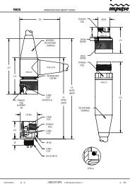
Appendix A: Mounting Bracket Drawing ................................................. 22<br />
<strong>ECO</strong> <strong>FLNTU</strong> <strong>User</strong>’s Guide (flntu) Revision Z 13 May 2009 i
1. Specifications<br />
Model <strong>FLNTU</strong>(RT)/D <strong>FLNTU</strong> <strong>FLNTU</strong>B <strong>FLNTU</strong>S <strong>FLNTU</strong>SB<br />
Mechanical<br />
Diameter<br />
6.3 cm<br />
Length 12.7 cm 25.4 cm 13.3 cm 26.0 cm<br />
6000 m 10.1 in (25.6 cm) --<br />
Weight in air 0.4 kg 0.96 kg 0.5 kg 0.96 kg<br />
6000 m 1.3 kg -- -- --<br />
Weight in water 0.02 kg 0.14 kg 0.08 kg 0.14 kg<br />
6000 m 0.75 kg --<br />
Material, std depth<br />
Acetal copolymer<br />
6000 m Titanium --<br />
Environmental<br />
Temperature range<br />
0–30 deg C<br />
Depth rating 600 m 300 m<br />
“deep” unit 6000 m --<br />
Optional pressure sensor N Y Yes<br />
Optional thermistor N Y Yes<br />
Electrical<br />
Digital output resolution<br />
12 bit<br />
Analog output signals<br />
0–5 V<br />
Internal data logging N Y Y<br />
Internal batteries N Y N Y<br />
Connector<br />
Input<br />
Current, typical<br />
Subconn MCBH6M<br />
7–15 VDC<br />
60 mA<br />
Current, sleep -- 150 µA<br />
Data memory -- 65,000 samples<br />
Sample rate<br />
to 8 Hz<br />
RS-232 output<br />
19200 baud<br />
Optional Anti-fouling<br />
bio-wiper<br />
N<br />
Y<br />
Bio-wiper cycle -- 140 mA<br />
Optical (Turbidity)<br />
Wavelength<br />
Sensitivity (min)<br />
Range, typical<br />
Optical (Fluorescence)<br />
Wavelength excitation<br />
Wavelength emission<br />
Sensitivity (per count)<br />
700 nm<br />
0.01 NTU<br />
0.01–25 NTU<br />
470 nm<br />
695 nm<br />
0.01 µg/l<br />
Range, typical<br />
0.01–50 µg/l<br />
Linearity (both signals) 99% R 2<br />
<strong>ECO</strong> <strong>FLNTU</strong> <strong>User</strong>’s Guide (flntu) Revision Z 13 May 2009 1
<strong>FLNTU</strong>(RT)—Provides analog or RS-232 serial output with 4,000-count range. This unit<br />
operates continuously when powered. Available with a 6,000 m depth rating.<br />
<strong>FLNTU</strong>—Provides the capabilities of the <strong>FLNTU</strong>(RT) with periodic sampling. Available with<br />
a 6,000 m depth rating.<br />
<strong>FLNTU</strong>S—Provides the capabilities of the <strong>FLNTU</strong> with an integrated anti-fouling bio-wiper<br />
and copper faceplate.<br />
<strong>FLNTU</strong>B—Provides the capabilities of the <strong>FLNTU</strong> with internal batteries for autonomous<br />
operation.<br />
<strong>FLNTU</strong>SB—Provides the capabilities of the <strong>FLNTU</strong>S with internal batteries for autonomous<br />
operation.<br />
2 <strong>ECO</strong> <strong>FLNTU</strong> <strong>User</strong>’s Guide (flntu) Revision Z 13 May 2009
2. <strong>ECO</strong> Meter Components<br />
The following subsections describe the bulkhead connectors, items delivered with the <strong>ECO</strong><br />
sensor, and optionally available equipment.<br />
2.1 Connectors<br />
<strong>ECO</strong>-Series meters use a six-pin bulkhead connector.<br />
Pin Function MCBH-6-MP<br />
1 Ground<br />
2 RS-232 RX<br />
3 NTU analog out<br />
4 V in<br />
5 RS-232 TX<br />
6 FL analog out<br />
Input power of 7–15 VDC is applied to V in (pin 4). The power supply current returns<br />
through the common ground pin (pin 1). The input power signal has a bi-directional filter.<br />
This prevents external power supply noise from entering into <strong>ECO</strong>-<strong>FLNTU</strong>, and also<br />
prevents internally generated noise from coupling out on to the external power supply wire.<br />
Data is sent out the serial output pin.<br />
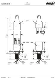
2.1.1 <strong>ECO</strong> <strong>FLNTU</strong>B, <strong>FLNTU</strong>SB Connectors<br />
<strong>FLNTU</strong>B and <strong>FLNTU</strong>SB (units with internal batteries) have a second bulkhead<br />
connector that comes with a jumper plug to supply power to the unit. The pin functions<br />
for this connector are shown below.<br />
<strong>ECO</strong> <strong>FLNTU</strong>B and <strong>FLNTU</strong>SB connector schematic<br />
<strong>ECO</strong> <strong>FLNTU</strong> <strong>User</strong>’s Guide (flntu) Revision Z 13 May 2009 3
Pinout summary for <strong>ECO</strong> <strong>FLNTU</strong>B/<strong>FLNTU</strong>SB<br />
Socket<br />
Function<br />
1 V in<br />
2 N/C<br />
3 Battery out<br />
<strong>FLNTU</strong>B and <strong>FLNTU</strong>SB (internal battery units) are supplied with a jumper plug that<br />
provides power from the internal batteries for autonomous operation.<br />
2.2 Delivered Items<br />
The standard <strong>ECO</strong> delivery consists of the following:<br />
• the instrument itself<br />
• dummy plug with lock collar<br />
• protective cover for optics<br />
• this user’s guide<br />
• <strong>ECO</strong>View user’s guide<br />
• <strong>ECO</strong>View host program and device files (on CD)<br />
• instrument-specific calibration sheet<br />
• Non-battery units only: stainless steel mounting bracket and hardware (See Appendix A<br />
for details)<br />
• Internal battery units: six 9-V Lithium batteries (installed)<br />
Spare Parts (equipment-dependent)<br />
• Fluorescent stick for bench testing<br />
• Bio-wiper units: one 3/32-in. hex key for bio-wiper removal<br />
• Bio-wiper units: Three 4-40 x 3/8 in. 316 stainless steel screws for securing bio-wiper<br />
• Internal battery units:<br />
o Two end flange O-rings (size 224) and two vent plug O-rings (size 010)<br />
o Two jacking screws for connector flange removal<br />
o One 3/32-in. hex key for jacking screws<br />
o Power plug for autonomous operation<br />
o Three pre-cut segments (7 inches) of 0.036-inch diameter monofilament for end flange<br />
o Three pre-cut segments (0.25 inches) of 0.094-inch diameter white nylon bar stock<br />
for replacing the white plastic dowel pin.<br />
2.3 Optional Equipment<br />
2.3.1 Test Cable<br />
A test cable is optionally available with each unit. This cable includes:<br />
1. An inline connector for providing power to the instrument from a user-supplied 9V<br />
battery.<br />
2. An auxiliary analog out connector.<br />
3. A second auxiliary analog out connector for NTU only.<br />
4. A DB-9 serial interface connector.<br />
5. A six-socket connector for providing power and signal to the instrument.<br />
4 <strong>ECO</strong> <strong>FLNTU</strong> <strong>User</strong>’s Guide (flntu) Revision Z 13 May 2009
2.3.2 Copper Faceplate<br />
<strong>ECO</strong> meters are optionally equipped with copper faceplates to improve the meter’s<br />
resistance to biofouling. Refer to Section 4.5.1 for important details on maintenance and<br />
cleaning.<br />
2.3.3 Bio-wiper and Copper Faceplate<br />
The <strong>FLNTU</strong>S and <strong>FLNTU</strong>SB are equipped with an integrated non-contact anti-fouling<br />
Bio-wiper and copper faceplate for use in extended deployments. This wiper can be<br />
manually controlled by a host controller package, or can perform autonomously as part of<br />
a pre-programmed sampling sequence upon instrument power-up. The rate of closure and<br />
opening is dependent upon both temperature and depth.<br />
Refer to Section 4.5.1 for important details on the maintenance and cleaning of the Biowiper<br />
and copper faceplate.<br />
WARNING!<br />
Do NOT rotate the Bio-wiper manually. This can damage the wiper motor and will<br />
void the warranty.<br />
2.3.4 Batteries<br />
<strong>ECO</strong> units with internal batteries are supplied with six 9-volt Lithium batteries as their<br />
power source. They can use either standard alkaline cells for a total capacity of<br />
approximately 1000 mA-hrs, or for longer deployments, LiMnO 2 cells to achieve more<br />
than 2000 mA-hrs of operational capacity. Actual total usage time of the internal<br />
batteries is a function of several parameters. These include nominal water temperature,<br />
sequence timing, sample periods, and total deployment duration.<br />
WARNING!<br />
Be sure to keep the dummy plug on the <strong>FLNTU</strong>B and <strong>FLNTU</strong>SB when not in use.<br />
For even greater deployment capability contact WET Labs for information on external<br />
battery packs.<br />
2.3.5 External Thermistor<br />
<strong>ECO</strong> meters are optionally equipped with an external thermistor. The thermistor is<br />
calibrated at WET Labs and the calibration coefficients are supplied on the instrument’s<br />
calibration sheets. Thermistor output is in counts and can be converted into engineering<br />
units using the instrument’s device file and <strong>ECO</strong>View software or the raw data can be<br />
converted in the user’s software (e.g. MATLAB or Excel) using the calibration equation:<br />
Temperature (deg C) = (Output * Slope) + Intercept<br />
2.3.6 Pressure Sensor<br />
<strong>ECO</strong> meters are optionally equipped with a strain gauge pressure sensor. The pressure<br />
sensor is calibrated at WET Labs and the calibration coefficients are supplied on the<br />
instrument’s calibration sheets. Pressure sensor output is in counts and can be converted<br />
into engineering units using the instruments device file and <strong>ECO</strong>View software or the<br />
<strong>ECO</strong> <strong>FLNTU</strong> <strong>User</strong>’s Guide (flntu) Revision Z 13 May 2009 5
aw data can be converted in the user's software (e.g. MATLAB or Excel) using the<br />
calibration equation:<br />
Relative Pressure (dbar) = (Output * Slope) + Intercept<br />
Please note that strain gauge pressure sensors are susceptible to atmospheric pressure<br />
changes and should be “zeroed” on each deployment or profile. The calibration equation<br />
for pressure above should be used first to get the relative pressure and the cast offset<br />
should then be subtracted to get the absolute pressure:<br />
Absolute Pressure (dbar) = Relative Pressure (dbar) - Relative Pressure at<br />
Atmospheric/Water interface (dbar)<br />
WARNING!<br />
Do not exceed the pressure sensor’s depth rating (see calibration sheet).<br />
Pressure Sensor Maintenance<br />
A plastic fitting filled with silicone oil provides a buffer between the pressure<br />
transducer and seawater. The transducer is both sensitive and delicate. Following the<br />
procedures below will ensure the best results and longest life from your pressure<br />
sensor.<br />
Pressure is transmitted from the water to the stainless steel transducer diaphragm via<br />
a plastic fitting filled with silicone oil. The inert silicone oil protects the pressure<br />
sensor from corrosion, which would occur after long exposure to salt water. The<br />
fitting will generally prevent the oil from escaping from the reservoir into the water.<br />
However, you may occasionally wish to ensure that oil remains in the reservoir on top<br />
of the transducer.<br />
WARNING<br />
Never touch or push on the transducer.<br />
1. Thoroughly clean the top of the instrument.<br />
2. Completely remove the white nylon Swagelock fitting using a 9/16-in. wrench.<br />
3. Check for obstructions in the tiny hole. Blow clear with compressed air or use a<br />
small piece of wire.<br />
4. Wipe clean the o-ring at the base of the Swagelock fitting.<br />
5. Screw the Swagelock fitting into the end flange until finger tight.<br />
6. Tighten it an additional 1/8 turn using a wrench only if necessary.<br />
7. Wipe up any excess oil.<br />
6 <strong>ECO</strong> <strong>FLNTU</strong> <strong>User</strong>’s Guide (flntu) Revision Z 13 May 2009
3. Theory of Operation<br />
The Environmental Characterization Optics (<strong>ECO</strong>) combination fluorometer and turbidity<br />
sensor allows the user to measure chlorophyll fluorescence at 470 nm and turbidity at 700 nm<br />
within the same volume.<br />
The fluorometer allows the user to monitor chlorophyll concentration by directly measuring the<br />
amount of chlorophyll-a fluorescence emission from a given sample volume of water.<br />
Chlorophyll, when excited by the presence of an external light source, absorbs light in certain<br />
regions of the visible spectrum and re-emits a small portion of this light as fluorescence at longer<br />
wavelengths. Two bright blue LEDs (centered at 455 nm and modulated at 1 kHz) provide the<br />
excitation source. A blue interference filter is used to reject the small amount of red light emitted<br />
by the LEDs. The blue light from the sources enters the water volume at an angle of<br />
approximately 55–60 degrees with respect to the end face of the unit. Fluoresced light is received<br />
by a detector positioned where the acceptance angle forms a 140-degree intersection with the<br />
source beam. A red interference filter is used to discriminate against the scattered blue excitation<br />
light. The red fluorescence emitted is synchronously detected by a silicon photodiode.<br />
Turbidity is measured simultaneously by detecting the scattered light from a 700 nm LED at 140<br />
degrees to the same detector used for fluorescence. The turbidity measurement is performed at<br />
the same 140 degree angle as the chlorophyll fluorescence.<br />
<strong>ECO</strong> <strong>FLNTU</strong> <strong>User</strong>’s Guide (flntu) Revision Z 13 May 2009 7
4. Instrument Operation<br />
Please note that certain aspects of instrument operation are configuration-dependent. These are<br />
noted where applicable within the manual.<br />
4.1 Initial Checkout<br />
Supplied from the factory, <strong>ECO</strong>s are configured to begin continuously sampling upon poweron.<br />
Electrical checkout of <strong>ECO</strong> is straightforward using the optional test cable.<br />
Connect the 6-socket connector on the test cable to the instrument to provide power to the<br />
LEDs and electronics (see Section 1 for a diagram of the pin-outs of <strong>ECO</strong>-<strong>FLNTU</strong>). Connect<br />
the battery leads on the test cable to the 9V battery supplied with the meter. Light should<br />
emanate from the meter.<br />
4.1.1 Analog Option<br />
Connect a digital multimeter (DMM) to the auxiliary leg of the test cable: the center of<br />
the RCA connector provides analog out signal and the outside provides ground. Auxiliary<br />
“chl” is the fluorometer output. Auxiliary “NTU” is the NTU output. With the sensor face<br />
clean and dry the instrument should read approximately 0.050–0.095 VDC. The analog<br />
signal will saturate at approximately 5 volts.<br />
4.2 Operating the Sensor for Data Output<br />
Note<br />
<strong>ECO</strong> scattering meters are sensitive to AC light. Before making measurement,<br />
turn AC lighting off.<br />
1. Connect the 6-socket connector to the instrument to provide power to the LEDs and<br />
electronics. Connect the DB-9 connector to a computer with the <strong>ECO</strong>View host program<br />
installed on it.<br />
WARNING!<br />
Always use a regulated power supply to provide power to <strong>ECO</strong> sensors if not using the 9V<br />
battery provided with the test cable: power spikes may damage the meter.<br />
2. Start <strong>ECO</strong>View. Select the appropriate COM Port and Device File. Supply power to the<br />
meter, then click on the Start Data button. Output will appear in the Raw Data window.<br />
Test the instrument’s signal using the fluorescent stick. <strong>ECO</strong> is sensitive to room lighting;<br />
for best results, perform test in ambient light only (turn off AC lighting). Remove the<br />
protective cover. Hold the fluorescent stick 1–4 cm above the optical paths in an<br />
orientation that maximizes exposure of the stick. (Parallel with the beams, not<br />
intersecting them). The signal will increase toward saturation (maximum value on<br />
characterization sheet). When applying power to sensors with a Bio-wiper, it will open<br />
and, depending on the settings, operate until you select Stop Data in <strong>ECO</strong>View (or input<br />
!!!!! in a terminal program) The Bio-wiper will close and the instrument will await<br />
the next command.<br />
8 <strong>ECO</strong> <strong>FLNTU</strong> <strong>User</strong>’s Guide (flntu) Revision Z 13 May 2009
3. If the sensor completes the requested samples (this is common for meters set up in<br />
moored applications), it will go into sleep mode, and the meter will not light when power<br />
is cycled. To “wake” the meter, click Stop Data five times at the rate of two times per<br />
second immediately upon applying power. This interrupts the sensor, returning it to a<br />
“ready” state, awaiting commands.<br />
4. Check the settings for the <strong>ECO</strong> and change if necessary. <strong>ECO</strong>View factory settings for<br />
continuous operation:<br />
Set Number of Samples = 0<br />
Set Number of Cycles = 0<br />
Internal Memory=On<br />
5. If the meter does not light after performing step 3, check the battery. Replace if<br />
necessary, perform steps 2 and 3 to verify communication. If it still does not light, contact<br />
WET Labs.<br />
Refer to the <strong>ECO</strong>View <strong>User</strong>’s Guide for details about using the software.<br />
4.3 Bio-wiper Operation<br />
The <strong>ECO</strong>-<strong>FLNTU</strong>S and -<strong>FLNTU</strong>SB are provided with an anti-fouling bio-wiper and<br />
faceplate that extend the possible deployment duration by retarding biological growth on the<br />
instrument’s optical surface. The Bio-wiper covers the optical surface: 1) while the<br />
instrument is in “sleep” mode; 2) when it has completed the number of samples requested;<br />
and 3) when the user selects Stop Data in <strong>ECO</strong>View or types “!!!!!” in a terminal program.<br />
When the meter wakes up, the optical surface is exposed by the Bio-wiper’s counterclockwise<br />
rotation.<br />
If power is shut off in mid cycle, the Bio-wiper will reinitialize to the beginning of the<br />
user-selected settings when power is applied again.<br />
4.4 Deployment<br />
WARNING!<br />
<strong>FLNTU</strong>B and <strong>FLNTU</strong>SB:<br />
Always check vent seal plug for full insertion immediately prior to deployment.<br />
Caution<br />
The <strong>FLNTU</strong> should be mounted so the LED source will not “see” any part of a cage or<br />
deployment hardware. This will compromise the sensor’s output.<br />
Once power is supplied to the <strong>ECO</strong> meter, the unit is ready for submersion and subsequent<br />
measurements. Some consideration should be given to the package orientation. Do not face<br />
the sensor directly into the sun or other bright lights. For best output signal integrity, locate<br />
the instrument away from significant EMI sources.<br />
<strong>ECO</strong> <strong>FLNTU</strong> <strong>User</strong>’s Guide (flntu) Revision Z 13 May 2009 9
Other than these basic considerations, one only needs to make sure that the unit is securely<br />
mounted to whatever lowering frame is used and that the mounting brackets are not damaging<br />
the unit casing.<br />
4.5 Upkeep and Maintenance<br />
After each cast or exposure of the instrument to natural water, flush with clean fresh water,<br />
paying careful attention to the sensor face. Use soapy water to cut any grease or oil<br />
accumulation. Gently wipe clean with a soft cloth. The sensor face is composed of ABS<br />
plastic and optical epoxy and can easily be damaged or scratched.<br />
WARNING!<br />
Do not use acetone or other solvents to clean the sensor.<br />
4.5.1 Bio-wiper and Faceplate Cleaning and Maintenance<br />
The Bio-wiper and the copper faceplate need to be removed from the meter for<br />
thorough cleaning to maximize anti-fouling capability.<br />
1. Be sure the meter is NOT powered or connected to a power source prior to<br />
uninstalling the Bio-wiper and faceplate.<br />
WARNING!<br />
<strong>Manual</strong>ly turning the motor shaft can damage the wiper motor and will void the warranty.<br />
Make sure the Bio-wiper is loosened from the shaft before attempting to rotate<br />
the Bio-wiper.<br />
2. Remove bio-wiper: Use the factory-supplied 3/32-in. hex key to loosen the screw<br />
that secures the wiper to the shaft on the instrument. It may be necessary to remove<br />
the screw from the clamping hole and screw it into the releasing hole, tightening it<br />
just enough to free the Bio-wiper from the shaft.<br />
clamping screw hole<br />
releasing screw hole<br />
3. Remove faceplate: Use a small Phillips screwdriver to remove the screws that attach<br />
the plate to the optics head.<br />
WARNING!<br />
Be sure to retain and re-use the factory-installed screws as they are vented for<br />
pressure compensation.<br />
10 <strong>ECO</strong> <strong>FLNTU</strong> <strong>User</strong>’s Guide (flntu) Revision Z 13 May 2009
4. Wash bio-wiper and/or copper faceplate with soapy water. Rinse and dry<br />
thoroughly. Note the condition of the copper on the instrument side of the wiper. It is<br />
normal for copper to corrode and turn green, especially after the instrument has been<br />
removed from the water. This corrosion will slightly reduce the shutter’s anti-fouling<br />
ability the next time it is deployed.<br />
5. Buff each with a pad of green Scotch Brite ® (or similar) until shiny.<br />
6. Clean the bio-wiper shaft and the shaft hole using an isopropyl alcohol-saturated<br />
cotton swab. Allow to dry.<br />
7. Re-install faceplate.<br />
8. Check the screw used to secure the bio-wiper to the shaft: a hex key must fit<br />
snugly into the screw socket. If the socket is in any way compromised, use a<br />
new screw (4-40 x 3/8 in. 316 stainless steel treated with anti-seize. These are<br />
shipped as part of the meter’s spare parts kit.)<br />
9. Slide the bio-wiper over the shaft. Be careful not to twist it on, thus rotating<br />
the shaft. If the wiper does not slide on easily, insert the screw into the expander<br />
hole, turning slowly until the bio-wiper slides easily onto the shaft.<br />
10. Rotate the bio-wiper into the closed position.<br />
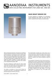
11. Set the gap between the bio-wiper and the instrument face to 0.03 in. (0.8 mm).<br />
An improperly set gap will either fail to clean the face or cause the motor to draw<br />
excessive current.<br />
To gauge 0.03 in., fold a piece of paper in<br />
half, then in half again, then fold a third time,<br />
creasing the edges. It’s now 8 sheets and<br />
about 0.03 in. thick.<br />
<strong>ECO</strong> <strong>FLNTU</strong> <strong>User</strong>’s Guide (flntu) Revision Z 13 May 2009 11
Not enough flex.<br />
Wiper may not be<br />
effective.<br />
Proper flex.<br />
Wiper maintains contact with<br />
instrument face and<br />
optical window.<br />
Too much flex.<br />
Wiper may cause too much<br />
friction, using excessive power.<br />
12. Use the 3/32-in. hex key to tighten the screw to “finger-tight,” then snug an additional<br />
quarter-turn.<br />
13. Run the instrument to verify operation. The bio-wiper must rotate 180 degrees to<br />
clear the optics before sampling, and 180 degrees to cover the optics after sampling.<br />
14. If the wiper needs adjusting, loosen the screw, make any necessary adjustments, and<br />
repeat steps 9 through 13 to ensure the wiper is performing properly.<br />
12 <strong>ECO</strong> <strong>FLNTU</strong> <strong>User</strong>’s Guide (flntu) Revision Z 13 May 2009
5. <strong>FLNTU</strong>B: Using Internal Batteries<br />
<strong>ECO</strong> sensors powered with internal batteries can either run directly from the internal<br />
batteries or can operate from power supplied by an external DC power supply (7–15<br />
volts). Internal-to-external source conversion is facilitated by a jumper plug that plugs<br />
into the unit’s bulkhead connector. When inserted, the plug forms a connection from the<br />
battery to the electronics power supply. By removing the plug, the instrument can be<br />
powered and communicate via a test or deployment cable. Setup conditions, instrument<br />
checkout, real-time operation, and data downloading are thus all achieved identically to<br />
the methods prescribed for the <strong>FLNTU</strong> and <strong>FLNTU</strong>S units.<br />
5.1 Removing End Flange and Batteries<br />
WARNING!<br />
Changing the batteries will require opening the pressure housing of the <strong>ECO</strong><br />
sensor. Only people qualified to service underwater oceanographic<br />
instrumentation should perform this procedure. If this procedure is performed<br />
improperly, it could result in catastrophic instrument failure due to flooding or in<br />
personal injury or death due to abnormal internal pressure as a result of flooding.<br />
WET Labs Inc. disclaims all product liability from the use or servicing of this<br />
equipment. WET Labs Inc. has no way of controlling the use of this equipment or<br />
of choosing qualified personnel to operate it, and therefore cannot take steps to<br />
comply with laws pertaining to product liability, including laws that impose a duty<br />
to warn the user of any dangers involved with the operation and maintenance of<br />
this equipment. Therefore, acceptance of this equipment by the customer shall be<br />
conclusively deemed to include a covenant by the customer to defend and hold<br />
WET Labs Inc. harmless from all product liability claims arising from the use and<br />
servicing of this equipment. Flooded instruments will be covered by WET Labs<br />
Inc. warranties at the discretion of WET Labs, Inc.<br />
1. Make sure the instrument is thoroughly dry.<br />
2. Remove the dummy plugs.<br />
3. With connector end flange pointed downwards away from face, release seal from<br />
vent plug.<br />
4. Remove moisture from vent plug area.<br />
5. Using needle nose pliers, remove filament from end flange.<br />
6. Lift flange from pressure housing until seal is broken. The jacking screws can<br />
be used to “push” the flange from the pressure housing and then can be<br />
removed or left in the end flange.<br />
<strong>ECO</strong> <strong>FLNTU</strong> <strong>User</strong>’s Guide (flntu) Revision Z 13 May 2009 13
7. Remove any excess moisture from flange–can seal area.<br />
8. Work end flange out of pressure housing and remove any residual moisture.<br />
Remove the gray foam spacer and the neoprene insulator.<br />
9. The battery pack is connected to the processor boards by a six-pin Molex<br />
connector: do NOT pull too hard or far on the battery pack or it will come<br />
unplugged and the unit will need to be returned to WET Labs.<br />
10. Gently pull the white cord at the loop to remove the battery pack from the<br />
pressure housing.<br />
11. Remove the black plastic protectors from the ends of the long screws securing the<br />
batteries.<br />
12. Loosen and remove the screws (3/16-in slotted driver).<br />
5.2 Replacing End Flange and Batteries<br />
1. Replace the batteries.<br />
2. Re-install the screws:<br />
• Align the groove in each of the plates so the six-wire extension bundle will fit<br />
in it along its length.<br />
• Be careful not to cross-thread into the bottom end plate nor to over-tighten the<br />
screws.<br />
• If they are too tight, the fiber washers that act as separators between the<br />
batteries will flex.<br />
• Make sure there are equal amounts of screw threads protruding from the<br />
bottom end plate when they are secure. This will ensure the pack is straight<br />
and will fit into the pressure housing with no difficulty.<br />
3. Re-install the black plastic protective covers on the ends of the screws.<br />
4. Remove and check the pressure housing O-ring for nicks or tears. Replace if<br />
necessary. Before re-installing, apply a light coat of vacuum grease on the O-ring.<br />
5. Carefully replace the battery pack in the pressure housing. Place the neoprene<br />
insulator on the battery assembly and lay the white cord on the top.<br />
6. Plug in the three-pin, then the six-pin Molex connectors. Sensor operation can<br />
now be tested if desired.<br />
7. Align the hole in the end flange (NOT the jack screw holes) with the white dowel<br />
pin. While coiling the six wire bundle and making sure none are pinched between<br />
the end flange and the pressure housing, position the flange on the housing. Leave<br />
14 <strong>ECO</strong> <strong>FLNTU</strong> <strong>User</strong>’s Guide (flntu) Revision Z 13 May 2009
space to re-insert the gray foam spacer, making sure the cut-out accommodates<br />
the vent plug screw.<br />
8. Push the end flange all the way on to the pressure housing, making sure no wires<br />
are pinched. Be sure the vent plug does not pop up. If it does, you’ll need to reposition<br />
the foam spacer.<br />
9. Re-insert the monofilament.<br />
5.3 Checking Vent Plug<br />
If there is fouling on the vent plug, it should be cleaned and the two 010 O-rings<br />
replaced. Otherwise, this mechanism should be maintenance-free.<br />
WARNING!<br />
The pressure housing is made of plastic material that scratches easily. Do not let<br />
the screwdriver slip and scratch the can when removing or replacing the vent<br />
plug. Use a toothpick (something softer than the plastic) to remove the O-rings<br />
from the vent plug.<br />
1. Pull vent plug out about half way; hold plug while unscrewing the truss screw.<br />
When screw is removed, pull vent plug from end flange.<br />
2. “Pinch” bottom O-ring around vent plug to form a small gap you can work a<br />
toothpick into. Use the toothpick to help roll the bottom O-ring off the plug.<br />
3. Perform the same procedure with the top O-ring.<br />
4. Clean the vent plug and vent plug hole using a dry lint-free tissue or cotton swab.<br />
5. Lightly coat two undamaged or new O-rings with silicon grease. Install the top O-<br />
ring (nearest to large end of plug) first, then the bottom one.<br />
6. Insert vent plug into its hole in the end flange and hold it while inserting the truss<br />
screw. Rotate the vent plug to begin tightening the screw. Finish tightening using<br />
a screwdriver, being careful not to over-tighten truss screw.<br />
Note<br />
A portion of the truss screw head has been removed to allow for venting in case<br />
of pressure buildup.<br />
<strong>ECO</strong> <strong>FLNTU</strong> <strong>User</strong>’s Guide (flntu) Revision Z 13 May 2009 15
6. Data Analysis<br />
Data from the <strong>ECO</strong> fluorometer and turbidity sensor, whether digital or analog, represents<br />
raw output from the sensor. Applying linear scaling constants, this data can be expressed in<br />
meaningful forms of chlorophyll fluorescence and NTUs.<br />
6.1 Scale Factor<br />
The scale factor is factory-calculated by obtaining a consistent output of a solution<br />
with a known concentration, then subtracting the meter’s dark counts. The scale<br />
factor, dark counts, and other characterization values are given on the instrument’s<br />
characterization sheet.<br />
Chlorophyll<br />
For chlorophyll, WET Labs uses the chlorophyll equivalent concentration (CEC) as<br />
the signal output using a fluorescent proxy approximately equal to 25 µg/l of a<br />
Thalassiosira weissflogii phytoplankton culture.<br />
Scale Factor = 25 µg/l ÷ (Chl Equivalent Concentration – dark counts)<br />
For example: 25 ÷ (3198 – 71) = 0.0080.<br />
NTU<br />
Scale Factor = xx ÷ (meter output – dark counts), where xx is the value of a<br />
Formazin concentration.<br />
For example: 12.2 ÷ (2011 – 50) = 0.0062.<br />
The scale factor is then applied to the output signal to provide the direct conversion of<br />
the output signal to chlorophyll concentration. WET Labs supplies a scale factor on<br />
the instrument-specific calibration sheet that ships with each meter. While this<br />
constant can be used to obtain approximate values, field calibration is highly<br />
recommended.<br />
6.2 Analog Response<br />
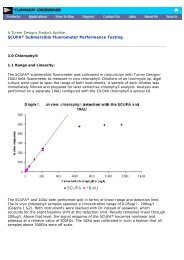
The <strong>ECO</strong>-<strong>FLNTU</strong> response is linear over the measurement range provided. Because<br />
of the varied environments in which each user will work, it is important to do<br />
calibrations using similar seawater as you expect to encounter in situ. Refer to the<br />
characterization section for further details. This will provide an accurate blank,<br />
equivalent phytoplankton types and similar physiological conditions for calculating<br />
the scale factor, thereby providing an accurate and meaningful calibration. Once a<br />
zero point has been determined and a scale factor established, the conversion of DC<br />
volts to chlorophyll concentration and NTUs is straightforward using the equations:<br />
16 <strong>ECO</strong> <strong>FLNTU</strong> <strong>User</strong>’s Guide (flntu) Revision Z 13 May 2009
Chlorophyll:<br />
[Chl] sample = (V output – V dc ) * Scale Factor<br />
where<br />
[Chl] sample = concentration of a chlorophyll sample of interest (µg/l)<br />
V output = output when measuring a sample of interest (VDC)<br />
V dc = dark counts, the measured signal output (in VDC) of meter in clean water<br />
with black tape over the detector<br />
Scale factor = multiplier in µg/l/volts<br />
NTU:<br />
[NTU] sample = (V output – V dc ) * Scale Factor<br />
where<br />
[NTU] sample = level of turbidity (NTU)<br />
V output = output when measuring a sample of interest (VDC)<br />
V dc = dark counts, the measured signal output (in VDC) of meter in clean water<br />
with black tape over the detector<br />
Scale factor = multiplier in NTU/volts<br />
6.3 Digital Response<br />
Digital data is processed in a similar fashion to analog data. Scaling is linear, and<br />
obtaining a “calibrated” output simply involves subtracting a digital offset value from<br />
output when measuring a sample of interest and multiplying the difference by the<br />
instrument scaling factor.<br />
Chlorophyll:<br />
[Chl] sample = (C output – C dc ) * Scale Factor<br />
where<br />
[Chl] sample = concentration of a chlorophyll sample of interest (µg/l)<br />
C output = output when measuring a sample of interest (counts)<br />
C dc = dark counts, the measured signal output of meter in clean water with black<br />
tape over the detector<br />
Scale factor = multiplier in µg/l/counts.<br />
NTU:<br />
[NTU] sample = (NTU output – C dc ) * Scale Factor<br />
where<br />
[NTU] sample = concentration of NTU solution<br />
NTU output = output when measuring a sample of interest (counts)<br />
C dc = dark counts, the measured signal output of meter in clean water with black<br />
tape over the detector<br />
Scale factor = multiplier in NTU/counts.<br />
<strong>ECO</strong> <strong>FLNTU</strong> <strong>User</strong>’s Guide (flntu) Revision Z 13 May 2009 17
7. Characterization and Testing<br />
<strong>ECO</strong> <strong>FLNTU</strong> is configured for a chlorophyll measurement range of 0.04–50 µg/l. The<br />
turbidity sensor’s measurement range is 0–25 NTU. Gain selection is done at WET Labs<br />
by setting several gain settings inside the instrument, and running a dilution series to<br />
determine the zero voltage offset and to ensure that the dynamic range covers the<br />
measurement range of interest. The dilution series also establishes the linearity of the<br />
instrument’s response. As is the case with other fluorometers, a detailed characterization<br />
must be done by the user to determine the actual zero point and scale factor for his/her<br />
particular use.<br />
The tests below ensure the meter’s performance.<br />
1. Dark counts: The meter’s baseline reading in the absence of source light is the dark<br />
count value. This is determined by measuring the signal output of the meter in clean,<br />
de-ionized water with black tape over the detector.<br />
2. Pressure: To ensure the integrity of the housing and seals, <strong>ECO</strong>s are subjected to a<br />
wet hyperbaric test before final testing. The testing chamber applies a water pressure<br />
of at least 40 PSI.<br />
3. Mechanical Stability: Before final testing, the <strong>ECO</strong> meters are subjected to a<br />
mechanical stability test. This involves subjecting the unit to mild vibration and<br />
shock. Proper instrument functionality is verified afterwards.<br />
4. Electronic Stability: This value is computed by collecting a sample once every<br />
second for twelve hours or more. After the data is collected, the standard deviation of<br />
this set is calculated and divided by the number of hours the test ran. The stability<br />
value must be less than 2.0 counts/hour.<br />
5. Noise: Noise is computed from a standard deviation over 60 samples. These samples<br />
are collected at one-second intervals for one minute. A standard deviation is then<br />
performed on the 60 samples, and the result is the published noise on the calibration<br />
form. The calculated noise must be below 2 counts.<br />
6. Voltage and Current Range Verification: To verify the <strong>ECO</strong> operates over the<br />
entire specified voltage range (7–15 V), a voltage test is performed at 7 and 15V, and<br />
the current draw and operation is observed. The current must remain constant at both<br />
7 and 15V.<br />
18 <strong>ECO</strong> <strong>FLNTU</strong> <strong>User</strong>’s Guide (flntu) Revision Z 13 May 2009
8. Terminal Communications<br />
As an alternative to the <strong>ECO</strong>View host software, <strong>ECO</strong> sensors can be controlled from a<br />
terminal emulator or customer-supplied interface software. This section outlines<br />
hardware requirements and low-level interface commands for this type of operation.<br />
8.1 Interface Specifications<br />
• baud rate: 19200 • data bits: 8 • parity: none<br />
• stop bits: 1 • flow control: none<br />
8.2 Command List<br />
Command Parameters passed Description<br />
!!!!! none Stops data collection; allows user to input setup parameters.<br />
Note that if the meter is in a sleep state, the power must be<br />
turned off for a minute, then powered on while the “!” key is<br />
held down for several seconds. If this does not “wake” the<br />
meter, refer to the <strong>ECO</strong>View user’s guide Operation Tip to<br />
“wake” a meter in a low power sleep state to enable inputting<br />
setup parameters.<br />
$ave single number, 1 to 65535 Number of measurements for each reported value<br />
$clk 24hr format time, hhmmss Sets the time in the Real Time Clock<br />
$dat date, format ddmmyy Sets the date in the Real Time Clock<br />
$emc none Erases the Atmel memory chip, displays menu when done<br />
$get none Reads data out of Atmel memory chip. Prints "etx" when<br />
completed.<br />
$int 24hr format time, hhmmss Time interval between packets in a set<br />
$mnu none Prints the menu, including time and date<br />
$pkt single number, 0 to 65535 Number of individual measurements in each packet<br />
$rec 1 (on) or 0 (off) Enables or disables recording data to Atmel memory chip<br />
$rls none Reloads settings from flash<br />
$run none Executes the current settings<br />
$set single number, 0 to 65535 Number of packets in a set<br />
$sto none Stores current settings to internal flash<br />
<strong>ECO</strong> <strong>FLNTU</strong> <strong>User</strong>’s Guide (flntu) Revision Z 13 May 2009 19
9. Device and Output Files<br />
Each meter is shipped with a CD containing the meter-specific device file, a sample output file,<br />
characterization information, and the applicable user’s guides.<br />
The <strong>ECO</strong>View host program requires a device file to provide engineering unit outputs for any of<br />
its measurements. Except for the first line in the device file, all lines of information in the<br />
device file that do not conform to one of the descriptor headers will be ignored. Every<br />
<strong>ECO</strong>View device file has three required elements: Plot Header, Column Count Specification,<br />
and Column Description.<br />
9.1 Plot Header<br />
The first line in the device file is used as the plot header for the <strong>ECO</strong>View Plots.<br />
9.2 Column Count Specification<br />
The Column Count Specification identifies how many columns of data to expect. It follows<br />
the format “Column=n.” The Column Count Specification must be present before any of the<br />
Column Descriptions are listed.<br />
9.3 Column Description<br />
Every column in the <strong>ECO</strong> meter’s output must have a corresponding Column Description in<br />
the device file. The following notation is used in identifying the elements of each Column<br />
Description.<br />
x = the column number, starting with 1 as the 1 st column<br />
sc = scale<br />
dc = dark counts: meter output in clean water with optics head taped<br />
mw = wavelength measured by the sensor<br />
dw = display wavelength: color to plot scattering data in<br />
v = measured volts dc<br />
Valid Column Descriptions are listed in the subsections below.<br />
9.3.1 Fluorescence Measurements<br />
CHL= x sc dc<br />
IENGR= x sc dc<br />
PHYCOERYTHRIN=x sc dc<br />
URANINE= x sc dc<br />
RHODAMINE= x sc dc<br />
CDOM= x sc dc<br />
9.3.2 Turbidity Measurements<br />
NTU= x sc dc<br />
9.3.3 Miscellaneous<br />
Date= x MMDD/YY<br />
Time= x HH:MM:SS<br />
N/U= x Not Used<br />
20 <strong>ECO</strong> <strong>FLNTU</strong> <strong>User</strong>’s Guide (flntu) Revision Z 13 May 2009
Scale, offset, and output are factory-set engineering unit calculations the user can manually<br />
adjust. Engineering units are displayed through <strong>ECO</strong>View in the Plot Data tab. Parameters<br />
for changing the internally calculated engineering units:<br />
iengrscale=sc<br />
iengroffset=off<br />
iengrunits=label where label is any continuous character string.<br />
9.4 Sample Device Files<br />
Below are sample device files for <strong>ECO</strong> <strong>FLNTU</strong> meters.<br />
9.4.1 Firmware Version 3.01 and Higher<br />
<strong>ECO</strong> <strong>FLNTU</strong>S-785<br />
Created on: 08/03/07<br />
COLUMNS= 7<br />
DATE= 1<br />
TIME= 2<br />
N/U= 3<br />
CHL= 4 0.0128 62.0<br />
N/U= 5<br />
NTU= 6 0.0063 85.0<br />
N/U= 7<br />
9.4.2 Firmware Versions Prior to 3.01<br />
<strong>ECO</strong> <strong>FLNTU</strong>S-045<br />
Created on: 07/03/03<br />
COLUMNS= 7<br />
DATE= 1<br />
TIME= 2<br />
REF= 3<br />
CHL= 4 0.0128 62.0<br />
REF= 5<br />
NTU= 6 0.0063 85.0<br />
N/U= 7<br />
9.5 Sample Output Files<br />
The reference column is unused by both firmware versions, but in 3.01 the emission<br />
wavelength of the chlorophyll signal and the scattering wavelength are displayed.<br />
9.5.1 Firmware Versions 3.01 and Higher<br />
Date<br />
(MM/DD/YY)<br />
Time<br />
(HH:MM:SS)<br />
λ<br />
CHL<br />
Signal<br />
<strong>ECO</strong> <strong>FLNTU</strong> <strong>User</strong>’s Guide (flntu) Revision Z 13 May 2009 21<br />
λ<br />
NTU<br />
Signal<br />
Thermistor<br />
08/03/07 11:22:51 695 49 700 69 536<br />
08/03/07 11:22:53 695 48 700 68 536<br />
08/03/07 11:22:54 695 49 700 68 536<br />
08/03/07 11:22:56 695 49 700 67 536<br />
08/03/07 11:22:58 695 47 700 69 536<br />
08/03/07 11:23:00 695 48 700 68 536<br />
9.5.2 Firmware Versions Prior to 3.01<br />
Date<br />
(MM/DD/YY)<br />
Time<br />
(HH:MM:SS)<br />
Chl Ref<br />
Chl<br />
Signal<br />
NTU<br />
Ref<br />
NTU<br />
Signal<br />
Thermistor<br />
05/01/03 10:06:51 1817 49 1583 69 536<br />
05/01/03 10:06:53 1818 48 1583 68 536<br />
05/01/03 10:06:54 1818 49 1583 68 536<br />
05/01/03 10:06:56 1818 49 1584 67 536<br />
05/01/03 10:06:58 1819 47 1584 69 536<br />
05/01/03 10:07:00 1819 48 1583 68 536
Appendix A:<br />
Mounting Bracket Drawing<br />
<strong>ECO</strong> <strong>FLNTU</strong> <strong>User</strong>’s Guide (flntu) Revision V 7 March 2007 22
Revision History<br />
Revision Date Revision Description Originator<br />
A 7/24/03 New document (DCR 322) H. Van Zee<br />
B 9/22/03 Correct syntax in 8.3.2 (DCR 336) H. Van Zee<br />
C 10/2/03 Add Terminal Communications section (DCR 337) H. Van Zee<br />
D 11/24/03<br />
Modify explanation for stop data collection command (DCR<br />
342) W. Strubhar<br />
E 11/25/03 Update specifications (DCR 338) I. Walsh<br />
F 2/17/04<br />
Update bio-wiper maintenance and column description for<br />
device files (DCR 367)<br />
A. Derr, I. Walsh<br />
G 3/10/04<br />
Add new test cable description, operational description,<br />
mounting diagram (DCR 381)<br />
A. Derr, D. Whiteman<br />
H 5/10/04 Delete warning about pins 3 and 6 (DCR 390) I. Walsh<br />
I 6/29/04 Update specifications (DCR 400) I. Walsh<br />
J 9/28/04<br />
Add text for optional thermistor and pressure sensor (DCR<br />
429) I. Walsh<br />
K 10/14/04<br />
Add references to Lithium batteries for applicable models<br />
(DCR 433)<br />
I. Walsh<br />
L 7/26/05<br />
Remove reference to Clean Water Offset, replace with<br />
Dark Counts<br />
M. Johnson<br />
H. Van Zee, R. Watte, C.<br />
Wetzel<br />
M 12/7/05 Clarify Section 6 (DCR 477)<br />
N 1/13/06 Clarify warranty statement (DCR 481) A. Gellatly, S. Proctor<br />
O 1/23/06 Add “deep” specs (DCR 483) D. Hankins, H. Van Zee<br />
P 3/3/06 Add copper faceplate (DCR 490, ECN 217) H. Van Zee, I. Walsh<br />
Q 5/31/06<br />
Correct reference to cleaning section, add annual<br />
maintenance recommendation (DCR 498)<br />
S. Proctor<br />
R 6/28/06<br />
Cleaning and maintenance of modified bio-wiper (ECN<br />
230, DCR 502) A. Derr, H. Van Zee<br />
S 7/27/06<br />
Change length of securing screw on bio-wiper (ECN # not<br />
assigned; DCR 504)<br />
J. da Cunha, H. Van Zee<br />
T 9/28/06 Update optical and electrical specifications (DCR 507) M. Johnson<br />
U 11/1/06<br />
Correct Pressure Sensor and Thermistor output equations<br />
(DCR 509)<br />
M. Johnson<br />
V 8/28/07<br />
Change unused Reference column in output to “N/U.”<br />
Correct battery units to 300 m depth rating. Remove<br />
reference to refilling silicone oil in pressure sensors (ECN<br />
251, DCR 513) M. Johnson, H. Van Zee<br />
Use one instead of two LEDs, (ECN 264) delete reference<br />
to refilling pressure sensor, update shipping requirements<br />
W 9/11/07 (DCR 531)<br />
Change dark counts derivation to reflect current production<br />
X 7/10/08 methodology (DCR 600)<br />
Update specs, correct Molex connector information (DCR<br />
Y 11/12/08 621) S. Lohse<br />
Z 5/13/09 Correct electronic stability test parameters (DCR 669) M. Johnson<br />
M. Johnson, H. Van Zee<br />
A. Barnard, M. Johnson,<br />
H. Van Zee<br />
<strong>ECO</strong> <strong>FLNTU</strong> <strong>User</strong>’s Guide (flntu) Revision Z 13 May 2009