Hinds PEM-90 v5
Hinds PEM-90 v5
Hinds PEM-90 v5

Create successful ePaper yourself
Turn your PDF publications into a flip-book with our unique Google optimized e-Paper software.
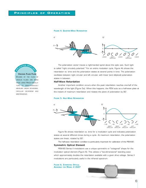
FIGURE 4. QUARTER-WAVE RETARDATION<br />
a)<br />
b)<br />
R =<br />
4<br />
4<br />
0<br />
4<br />
LINEAR<br />
RIGHT<br />
CIRCULAR<br />
LINEAR<br />
LEFT<br />
CIRCULAR<br />
LINEAR<br />
The polarization vector traces a right-handed spiral about the optic axis. Such light<br />
is called "right circularly polarized." For an entire modulator cycle, Figure 4b shows the<br />
VISCOUS FLUID FLOW<br />
STUDIES OF THE FLOW OF<br />
VISCOUS FLUIDS ARE BEING<br />
MADE USING HINDS MODULA-<br />
TORS TO SIMULTANEOUSLY<br />
MEASURE LINEAR DICHROISM,<br />
CIRCULAR DICHROISM AND<br />
BIREFRINGENCE.<br />
retardation vs. time and the polarization states at several points in time. The polarization<br />
oscillates between right circular and left circular, with linear (and elliptical) polarization<br />
states in between.<br />
Half-Wave Retardation<br />
Another important condition occurs when the peak retardation reaches one-half of the<br />
wavelength of the light (Figure 5a). When this happens, the <strong>PEM</strong> acts as a half-wave plate at<br />
the instant of maximum retardation and rotates the plane of polarization by <strong>90</strong>˚.<br />
FIGURE 5. HALF-WAVE RETARDATION<br />
a)<br />
b)<br />
R =<br />
2<br />
2<br />
0<br />
2<br />
+ 45 - 45 + 45 - 45 + 45<br />
RIGHT<br />
CIRCULAR<br />
RIGHT<br />
CIRCULAR<br />
LEFT<br />
CIRCULAR<br />
LEFT<br />
CIRCULAR<br />
Figure 5b shows retardation vs. time for a modulator cycle and indicates polarization<br />
states at several different times during a cycle. At maximum retardation, the polarization<br />
states are linear, rotated by <strong>90</strong>˚.<br />
The half-wave retardation condition is particularly important for calibration of the <strong>PEM</strong>-<strong>90</strong>˚.<br />
Symmetric Optical Element<br />
<strong>PEM</strong>-<strong>90</strong> Series II modulators use a unique symmetric or "octagonal" shape for the<br />
modulator optical element (Figure 6). This utilizes a "two-dimensional" standing wave<br />
which approximately doubles the retardation available with a given drive voltage. Series II<br />
modulators are particularly useful in the infrared spectrum.<br />
FIGURE 6. SYMMETRIC OPTICAL<br />
ASSEMBLY FOR MODEL II/ZS37<br />
6