pdf file - Plasma Science and Fusion Center - MIT
pdf file - Plasma Science and Fusion Center - MIT
pdf file - Plasma Science and Fusion Center - MIT

Create successful ePaper yourself
Turn your PDF publications into a flip-book with our unique Google optimized e-Paper software.
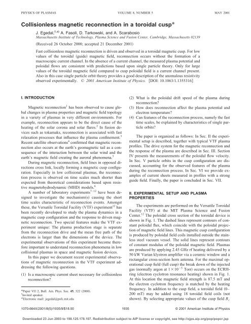
PHYSICS OF PLASMAS VOLUME 8, NUMBER 5 MAY 2001<br />
Collisionless magnetic reconnection in a toroidal cusp*<br />
J. Egedal, †,a) A. Fasoli, D. Tarkowski, <strong>and</strong> A. Scarabosio<br />
Massachusetts Institute of Technology, <strong>Plasma</strong> <strong>Science</strong> <strong>and</strong> <strong>Fusion</strong> <strong>Center</strong>, Cambridge, Massachusetts 02139<br />
Received 26 October 2000; accepted 21 December 2001<br />
Fast collisionless magnetic reconnection is driven <strong>and</strong> observed in a toroidal magnetic cusp. For low<br />
values of the toroidal guide magnetic field, reconnection occurs without the formation of a<br />
macroscopic current channel. In the absence of a current channel, the measured plasma potential <strong>and</strong><br />
poloidal flows are consistent with predictions based upon single particle theory. Only for large<br />
values of the toroidal magnetic field compared to cusp poloidal field is a current channel present.<br />
Also in this case single particle orbit theory provides a good description of the anomalous resistivity<br />
observed experimentally. © 2001 American Institute of Physics. DOI: 10.1063/1.1355316<br />
I. INTRODUCTION<br />
Magnetic reconnection 1 has been observed to cause global<br />
changes in plasma properties <strong>and</strong> magnetic field topology<br />
in a variety of plasmas in very different environments. For<br />
example, reconnection appears to be the direct cause of the<br />
heating of the solar corona <strong>and</strong> solar flares. 2 In fusion devices<br />
such as tokamaks, reconnection is associated with fast<br />
relaxation processes that influence the plasma confinement. 3<br />
Recent satellite observations 4 confirmed that magnetic reconnection<br />
also occurs at the earth’s geomagnetic tail as a consequence<br />
of the interaction between the solar wind <strong>and</strong> the<br />
earth’s magnetic field creating the auroral phenomena. 5<br />
During magnetic reconnection, field lines in opposed directions<br />
cross link, locally forming a magnetic cusp configuration.<br />
Especially in low collisional plasmas, the reconnection<br />
process is observed on time scales much shorter than<br />
expected from theoretical considerations based upon resistive<br />
magnetohydrodynamic MHD models. 6<br />
A number of laboratory experiments 7–12 have been designed<br />
to investigate the mechanisms causing the short<br />
time scales characteristic of reconnection events. Amongst<br />
these, the Versatile Toroidal Facility VTF experiment 12 has<br />
been recently developed to study the plasma dynamics in a<br />
magnetic cusp configuration <strong>and</strong> the response to driven magnetic<br />
reconnection. Two special features make the VTF experiment<br />
unique: The plasma production stage is separate<br />
from the reconnection drive <strong>and</strong> the mean free path of the<br />
electrons is larger than the dimensions of the device. The<br />
experimental observations of this experiment become therefore<br />
important to underst<strong>and</strong> reconnection phenomena in low<br />
collisional plasmas in space <strong>and</strong> magnetic fusion devices.<br />
In this paper we document recent experimental observations<br />
of magnetic reconnection in the VTF experiment addressing<br />
the following questions.<br />
1 Is a macroscopic current sheet necessary for collisionless<br />
reconnection?<br />
*Paper VI1 2, Bull. Am. Phys. Soc. 45, 322 2000.<br />
† Invited speaker.<br />
a Electronic mail: jegedal@psfc.mit.edu<br />
2 What is the poloidal drift speed of the plasma during<br />
reconnection?<br />
3 How does reconnection affect the plasma potential <strong>and</strong><br />
electron temperature?<br />
4 Can features of the reconnection process, namely the fast<br />
time scales, be explained by characteristics of single particle<br />
orbits?<br />
The paper is organized as follows: In Sec. II the experimental<br />
setup is described, together with typical VTF plasma<br />
pro<strong>file</strong>s. The drive system for the magnetic reconnection <strong>and</strong><br />
the response of the plasma are described in Sec. III. Section<br />
IV presents the measurements of the poloidal flow velocity.<br />
In Sec. V particle orbits in the cusp configuration are discussed,<br />
accounting for the observed features of the plasma<br />
during the reconnection process. In Sec. VI we provide examples<br />
of current sheets measured in pro<strong>file</strong>s with a strong<br />
guide field. Finally, the paper is concluded in Sec. VII.<br />
II. EXPERIMENTAL SETUP AND PLASMA<br />
PROPERTIES<br />
The experiments are performed on the Versatile Toroidal<br />
Facility VTF at the <strong>MIT</strong> <strong>Plasma</strong> <strong>Science</strong> <strong>and</strong> <strong>Fusion</strong><br />
<strong>Center</strong>. 12 The poloidal cross section of the toroidal device is<br />
shown in Fig. 1. The dashed lines represent contours of constant<br />
poloidal flux, which coincide with the poloidal projection<br />
of magnetic field lines. This magnetic cusp configuration<br />
is produced by poloidal field coils installed outside the stainless<br />
steel vacuum vessel. The solid lines represent contours<br />
of constant modulus of the poloidal magnetic field. <strong>Plasma</strong>s<br />
are produced by applying 2.45 GHz rf heating delivered by a<br />
50 kW Varian klystron amplifier via a ceramic window <strong>and</strong> a<br />
rectangular cross-section horn antenna. For the maximal operational<br />
cusp field full cusp the break down of the injected<br />
gas normally argon at 110 5 Torr occurs on the ECRHring<br />
electron cyclotron resonance heating shown in Fig. 1.<br />
At this location the magnetic field strength is 87.5 mT <strong>and</strong><br />
the electron cyclotron frequency is matched by the heating<br />
frequency. In addition to the cusp field, a toroidal field 0–<br />
200 mT may be added using 18 toroidal field coils not<br />
shown. By selecting appropriate values of the cusp field B c<br />
1070-664X/2001/8(5)/1935/9/$18.00<br />
1935<br />
© 2001 American Institute of Physics<br />
Downloaded 23 Jun 2003 to 198.125.178.107. Redistribution subject to AIP license or copyright, see http://ojps.aip.org/pop/popcr.jsp
1936 Phys. <strong>Plasma</strong>s, Vol. 8, No. 5, May 2001 Egedal et al.<br />
FIG. 1. Poloidal cross section of VTF. The solid contour<br />
lines represent the poloidal magnetic field strength.<br />
The dashed contour lines correspond to constant levels<br />
of the poloidal magnetic flux, , which coincide with<br />
magnetic field lines.<br />
<strong>and</strong> the toroidal field B , it is possible to modify the shape<br />
<strong>and</strong> location of the ECRH-ring. Highly reproducible target<br />
plasmas are produced during shots lasting up to 100 ms <strong>and</strong><br />
taken typically every 2 minutes.<br />
The snapshots in time of the steady state density pro<strong>file</strong>s<br />
shown in Fig. 2 were measured by a 16-tip Langmuir probe<br />
moved though the plasma 29 plasma shots per pro<strong>file</strong>. For<br />
each magnetic configuration the location of the ECRH-ring<br />
is indicated by the red lines. The plasma is confined partly by<br />
mirror effects 12 <strong>and</strong> partly electrostatically.<br />
The pro<strong>file</strong> in Fig. 2A was obtained in the absence of<br />
toroidal magnetic field. In this case the magnetic moment is<br />
not conserved for the particles on field lines passing through<br />
the region of the absolute magnetic null. As a consequence,<br />
the measured density is reduced along the separatrix. In Fig.<br />
2B a small toroidal component (B 30 mT is added, improving<br />
the confinement of the particles on the separatrix.<br />
The 1/R dependence of the toroidal magnetic field<br />
strength makes it possible to place the ECRH-ring to the<br />
right of the X point. The density pro<strong>file</strong>s obtained in two<br />
such examples are given in Figs. 2C <strong>and</strong> 2D.<br />
The pro<strong>file</strong>s in Fig. 3 were obtained by sweeping the<br />
bias on the multiple Langmuir probe tips. Electron temperatures<br />
in the range of 20 eV are typical for the VTF plasmas.<br />
The plasma potential is, for most of the possible configurations,<br />
in the range of 60 to 100 V.<br />
III. RECONNECTION DRIVE SYSTEM AND RESPONSE<br />
OF THE PLASMA<br />
For driving magnetic reconnection VTF is equipped with<br />
a 1 mH ohmic coil system fed through a semiconductor<br />
switch by a1mFcapacitor. 12 The capacitor is charged to 3<br />
kV. As shown in Fig. 4, the LC resonance circuit produces<br />
sinusoidal current pulses inducing electric field pulses of 10<br />
V/m in the center of the vacuum vessel.<br />
The density contours in Fig. 5A represent another example<br />
where the plasma is produced entirely to the right of<br />
the X line. According to ideal MHD it should not be possible<br />
for this plasma to cross the separatrix into the quadrants to<br />
the left of the X line. However, as seen in Figs. 5B <strong>and</strong><br />
5C, during the electric field pulses the plasma drifts unhindered<br />
across the separatrix. The direction of the drifts in the<br />
plasma agrees with the EB drift. The measurements described<br />
in the next section show that the drift velocity is<br />
given by E /B cusp .<br />
During the reconnection experiments, the time evolution<br />
of the magnetic flux over the plasma cross section is measured<br />
by a multiple magnetic probe. This movable probe has<br />
30 pick-up coils each with a total area of 0.5 cm 2 for each<br />
of the three direction in space, providing a spatial resolution<br />
of 1 cm in the radial direction. Due to the reproducibility of<br />
the VTF plasma the resolution in the vertical direction can be<br />
made arbitrarily fine by moving the probe in between plasma<br />
shots. The signals are integrated ( int 0.5 ms <strong>and</strong> amplified<br />
gain100 before digitization.<br />
These magnetic measurements reproduce the magnetic<br />
fields obtained in the absence of plasma. In turn, these measurements<br />
agree with the fields calculated on the basis of the<br />
currents applied in the VTF magnetic coils system. Hence,<br />
we see no evidence of currents in the plasma. Taking into<br />
account the sensitivity of the magnetic probes, it can be concluded<br />
that the total toroidal current induced in the plasma is<br />
less than 5 A. If classical Spitzer resistivity were valid for the<br />
experimental configuration, a current of the order of 10 kA<br />
should have been observed.<br />
Significant plasma currents are only observed in pro<strong>file</strong>s<br />
where the maximal poloidal magnetic field in the cross section<br />
is less than 2% of the toroidal field see Sec. VI.<br />
Downloaded 23 Jun 2003 to 198.125.178.107. Redistribution subject to AIP license or copyright, see http://ojps.aip.org/pop/popcr.jsp
Phys. <strong>Plasma</strong>s, Vol. 8, No. 5, May 2001<br />
Collisionless magnetic reconnection in a toroidal cusp<br />
1937<br />
FIG. 2. Color Contours of electron density in various<br />
magnetic configurations.<br />
IV. MEASUREMENT OF THE POLOIDAL DRIFT SPEED<br />
Flows with directions consistent with the EB drift<br />
have been measured in VTF during reconnection using a<br />
Mach probe. 12 However, the numerical value of the flow<br />
speed was not accurately obtained using this method. In order<br />
to accurately measure the drift speed of the plasma during<br />
the reconnection process, experiments were conducted<br />
where the rf heating is pulsed at 2 kHz with a duty cycle of<br />
12%. Using a sampling rate of 20 kHz for the acquisition of<br />
the ion saturation current signals measured by the Langmuir<br />
probe, the evolution of the decaying plasma density pro<strong>file</strong><br />
is monitored with good time resolution during the time intervals<br />
where no rf heating is applied. Figure 6 shows the time<br />
history of the rf heating A, the electric field induced B,<br />
<strong>and</strong> the resulting ion saturation current on one of the Langmuir<br />
probe tips C.<br />
The evolution of the plasma density is obtained throughout<br />
the poloidal cross section as a function of time. It is<br />
found that the plasma density is at all times nearly constant<br />
along the magnetic field lines. We may therefore illustrate<br />
the experimental results by plotting contours of the density<br />
as function of the magnetic flux <strong>and</strong> t. The contours<br />
FIG. 3. Color Contours of density, temperature, pressure<br />
<strong>and</strong> plasma potential in a magnetic configuration<br />
with full cusp <strong>and</strong> B 80 mT.<br />
Downloaded 23 Jun 2003 to 198.125.178.107. Redistribution subject to AIP license or copyright, see http://ojps.aip.org/pop/popcr.jsp
1938 Phys. <strong>Plasma</strong>s, Vol. 8, No. 5, May 2001 Egedal et al.<br />
shown in Fig. 6D are obtained by evaluating the density<br />
along the poloidal location indicated by the dashed red line<br />
in Fig. 5D. The data used in creating the diagram in Fig.<br />
6D corresponds to data samples obtained at constant time<br />
interval t0.5 ms after the rf heating pulses.<br />
Similarly, the data used in creating the diagrams in Figs.<br />
7 was obtained with t0.3, 0.5 ms. The value of l 0<br />
B /B cusp for the magnetic configuration of Fig. 6 <strong>and</strong><br />
Figs. 7A <strong>and</strong> 7B is 0.3 m, whereas l 0 0.5 m for the<br />
magnetic configurations forming the basis for the data shown<br />
in Figs. 7C <strong>and</strong> 7D. In the diagram of Fig. 6D <strong>and</strong> the<br />
four diagrams in Fig. 7 the locations of the plasma boundaries<br />
are well defined <strong>and</strong> coincide with the location of the<br />
black dashed lines. These lines obtained through (t)<br />
tRE (t) represent the theoretical location of the plasma<br />
boundary assuming that the plasma is frozen into the poloidal<br />
magnetic flux. Hence, we find experimentally that the<br />
plasma is frozen into the poloidal magnetic flux. Due to the<br />
absence of a detectable toroidal current <strong>and</strong> an associate diffusion<br />
region, the poloidal magnetic field reconnect unhindered<br />
<strong>and</strong> arbitrarily fast. The rate of reconnection in the<br />
VTF experiment is solely determined by the operator by imposing<br />
a given value of the induced toroidal electric field.<br />
The poloidal drift speed, expressed in terms of the flux<br />
variable, d/dtRE , translates into a drift speed in real<br />
space given by v d E /B cusp , independent of the toroidal<br />
magnetic field. In the presence of a toroidal magnetic field,<br />
this drift speed is much larger than usual EB drift speed<br />
given by E /B inferred on the basis of the induced electric<br />
field where B is the total magnetic field.<br />
FIG. 4. Loop voltage induced by the ohmic pulse on a copper wire at the<br />
center of the vessel.<br />
V. INTERPRETATION OF EXPERIMENTAL RESULTS<br />
ON THE BASIS OF SINGLE PARTICLE ORBITS<br />
The mean free path between collisions for the electrons<br />
in VTF is in the order of 5 m. The thermal speed of the<br />
electrons is typically 110 6 m/s, so during a particle confinement<br />
time, p 0.2 ms, the electrons execute hundreds of<br />
complete particle bounce orbits in the poloidal cross sections.<br />
It is therefore natural to seek the explanation for the<br />
observed plasma behavior in the properties of the particle<br />
orbits.<br />
The particle confinement in the VTF device is analyzed<br />
in Ref. 12, based upon the guiding center approximation. In<br />
Ref. 13 an analysis was given for the particle orbits in a<br />
linear magnetic cusp including <strong>and</strong> electric field along the<br />
direction of the X line, summarized here below.<br />
The crucial mechanism for confining the particles in a<br />
magnetic cusp is the adiabatic invariance of the magnetic<br />
moment mv 2 /(2B), where v is the particle velocity<br />
perpendicular to the magnetic field. We assume that a sufficient<br />
magnetic guide field in the direction of the X line is<br />
present, such that the magnetic moment is conserved at all<br />
locations throughout the cross section. In the absence of an<br />
electric field the particles gyrate around specific field lines<br />
<strong>and</strong> are confined to regions of the magnetic configuration<br />
where BE k . Here E k is the particle kinetic energy, which,<br />
FIG. 5. Color Density contours measured before, during<br />
<strong>and</strong> after an ohmic pulse. The ohmic pulse induces<br />
EB-flows, the directions of which are illustrated by<br />
the red arrows in B <strong>and</strong> C, which perturb the shape<br />
of the density pro<strong>file</strong>. The red dashed lines in D indicate<br />
the locations along which the plasma density is<br />
evaluated in Figs. 6 <strong>and</strong> 7 as a function of time <strong>and</strong> the<br />
magnetic flux variable .<br />
Downloaded 23 Jun 2003 to 198.125.178.107. Redistribution subject to AIP license or copyright, see http://ojps.aip.org/pop/popcr.jsp
Phys. <strong>Plasma</strong>s, Vol. 8, No. 5, May 2001<br />
Collisionless magnetic reconnection in a toroidal cusp<br />
1939<br />
FIG. 6. Color Experimental scheme for measuring the<br />
poloidal flow of the plasma during an ohmic pulse. A<br />
The rf power is pulsed at 2 kHz with a duty cycle of<br />
12%. B Time history of induced electric field. C The<br />
resulting ion saturation current measured on a single<br />
probe tip. D Density contours as a function of <strong>and</strong><br />
t, using data samples measured t0.5 ms after the rf<br />
pulses.<br />
FIG. 7. Color <strong>Plasma</strong> density measured as a function<br />
of <strong>and</strong> t during two ohmic pulses for two different<br />
plasma configurations: A, B full cusp; C, D half<br />
cusp. The data is measured at, respectively, t0.3<br />
ms <strong>and</strong> t0.5 ms after the rf pulses. The dashed lines<br />
indicate the theoretical location of the plasma edges<br />
when the plasma moves across field lines with the<br />
speed v d E z /B p .<br />
Downloaded 23 Jun 2003 to 198.125.178.107. Redistribution subject to AIP license or copyright, see http://ojps.aip.org/pop/popcr.jsp
1940 Phys. <strong>Plasma</strong>s, Vol. 8, No. 5, May 2001 Egedal et al.<br />
FIG. 8. Trajectories of an argon ion in a linear magnetic cusp, see text.<br />
in the absence of an electric field, is a constant of motion.<br />
Since the strength of the magnetic cusp field varies linearly<br />
with the distance from the center of the X line, the particles<br />
are confined to a certain region of a field line. The points<br />
where BE k are the orbit bounce points. Here the velocity<br />
component v , parallel to the magnetic field, changes sign<br />
<strong>and</strong> the particle is reflected back along the same field line.<br />
With an electric field E in the direction of X line, the<br />
particle can gain or lose a certain energy E as it travels<br />
along a field line. The sign <strong>and</strong> value of E depend on the<br />
specific magnetic configuration. The orbit bounce points are<br />
now shifted to the location where BE k E. For now,<br />
the exact location of the bounce point is not important. What<br />
is important is that the particles are trapped even when an<br />
electric field is present. Apart from deviations due to the E<br />
B, curvature <strong>and</strong> B drifts across field lines, the particle<br />
will mirror back along the path it initially followed. Due to<br />
this trapping, when the orbit motion is averaged over one<br />
orbit bounce time, the particle conducts no current in the<br />
direction of the induced electric field. This situation is similar<br />
to the trapped particles in tokamaks, which do not contribute<br />
to the toroidal conductivity. The main difference is<br />
that in a cusp configuration all particles are trapped, including<br />
particles on the separatrix. Therefore in the absence of<br />
collisional detrapping the plasma has no conductivity in the<br />
direction of the X line.<br />
Figure 8A shows an example of an orbit of a 15 eV<br />
single ionized argon ion in a linear magnetic cusp: B<br />
b 0 (xxˆyŷl 0 ẑ). The orbit is calculated for b 0 0.3 T/m<br />
<strong>and</strong> l 0 0.25 m, for a homogeneous electric field E z 10<br />
V/m imposed along the direction of the X line. Figure 8B<br />
shows the guiding center representation of the same orbit.<br />
We note how the argon ion practically follows the magnetic<br />
field lines trapped between the dashed lines B1 <strong>and</strong> B2. The<br />
ion is not conducting any current in the negative z direction,<br />
rather it experiences a drift in the positive z direction as it<br />
approaches the separatrix.<br />
In Ref. 14 it was found that trapped particles in tokamaks<br />
in the presence of a toroidal electric field, E , experience<br />
a pinch effect known as the Ware pinch causing the<br />
trapped particles to drift across the poloidal cross section at<br />
the speed v d E /B p , where B p is the poloidal magnetic<br />
field strength. By arguments similar to those applied in the<br />
paper by Ware we find 13 that all particles in the cusp are<br />
subject to this pinch effect <strong>and</strong> drift across the cross section<br />
at the Ware pinch speed. This is exactly the speed that is<br />
measured experimentally see Figs. 5 <strong>and</strong> 6.<br />
As discussed above, the gain in energy of the particle as<br />
it moves along the B-field line in the direction of the electric<br />
field causes a shift in the location of the bounce point. This<br />
explains why the loci of the bounce points B1 <strong>and</strong> B2 in Fig.<br />
8B are not symmetric around the lines yx. The<br />
bounce points are found to be shifted in the positive y direction.<br />
Similarly, for the electrons one finds that the bounce<br />
points are shifted in the positive x direction. In a plasma, this<br />
macroscopic separation of the charges is not possible: An<br />
electrostatic potential will build up enforcing charge<br />
quasineutrality. Note that an electrostatic potential in the<br />
cross section does not influence the Ware pinch drift. Macroscopic<br />
charge separation is avoided if the particles do not<br />
experience a change in energy as they move along field<br />
lines. 13 This requires the electrostatic potential<br />
0.5E z l 0 logx/y.<br />
This potential was included when calculating the particle orbit<br />
shown in Fig. 8C. The argon ion now bounces symmetrically<br />
around the lines yx, while drifting with the<br />
magnetic field lines at the Ware pinch speed.<br />
A direct measurement of the electrostatic potential was<br />
conducted on VTF during driven reconnection. The data<br />
shown in Fig. 9 was obtained under conditions identical to<br />
those used when obtaining the data shown in Figs. 3 <strong>and</strong> 5.<br />
The diagrams A–C show the changes in the plasma density,<br />
electron temperature, <strong>and</strong> plasma potential obtained by<br />
Downloaded 23 Jun 2003 to 198.125.178.107. Redistribution subject to AIP license or copyright, see http://ojps.aip.org/pop/popcr.jsp
Phys. <strong>Plasma</strong>s, Vol. 8, No. 5, May 2001<br />
Collisionless magnetic reconnection in a toroidal cusp<br />
1941<br />
FIG. 9. Color A–C Changes in plasma parameters<br />
as a response to the induced reconnection electric field<br />
E . D The theoretical predicted change given in the<br />
plasma potential. The intervals above the figures correspond<br />
to the full range 1, 1 in the color code.<br />
subtracting two pro<strong>file</strong>s for each of these quantities measured<br />
during periods with opposite sign of the induced electric<br />
field. It is seen that the changes in density <strong>and</strong> temperature<br />
are very modest, implying that no significant heating of the<br />
electrons is taking place during the magnetic reconnection<br />
process. We attribute the changes which are present to the<br />
induced flows combined with the localized ECR-heating of<br />
the plasma.<br />
In the area of the dashed field lines the density <strong>and</strong> temperature<br />
remain constant under the sign reversal of the reconnecting<br />
electric field. In this area the measured change in<br />
plasma potential is consistent with the theoretical change<br />
given by the equation above.<br />
Besides the induced electric field E , the total electric<br />
field E in the plasma includes the contribution from<br />
the electrostatic potential. The total electric field is perpendicular<br />
to the magnetic field <strong>and</strong> the frozen in-law, E<br />
v EB B0, is fulfilled at all locations where the actual<br />
electrostatic potential in the plasma agrees with the expression<br />
of calculated above. Here v EB EB/B 2 is the<br />
usual EB drift. Note that the poloidal component of v EB<br />
is indeed the pinch speed E /B cusp , independent of .<br />
FIG. 10. Color Density contours measured during the<br />
formation of current layers for four different ratios between<br />
the toroidal field <strong>and</strong> the cusp fields: l 0<br />
B /B cusp 23,17,12 m. The dashed lines represent<br />
contours of constant poloidal magnetic flux.<br />
Downloaded 23 Jun 2003 to 198.125.178.107. Redistribution subject to AIP license or copyright, see http://ojps.aip.org/pop/popcr.jsp
1942 Phys. <strong>Plasma</strong>s, Vol. 8, No. 5, May 2001 Egedal et al.<br />
FIG. 11. Color Contours measured current densities<br />
for the same conditions as in Fig 10. The dashed lines<br />
represent contours of constant poloidal magnetic flux.<br />
VI. MEASUREMENTS OF CURRENT SHEETS<br />
In magnetic configurations where the toroidal magnetic<br />
field is much stronger than the cusp field, the majority of the<br />
particles are no longer trapped. In such configurations we do<br />
indeed find a current sheet. In Figs. 10 <strong>and</strong> 11 snap shots in<br />
time of the plasma density <strong>and</strong> current density at the beginning<br />
of the formation of the current layers are shown. These<br />
correspond to the formation of current sheets for three different<br />
values of the ratio of toroidal field <strong>and</strong> cusp field: l 0<br />
B /B cusp 23, 17, 12 m note that the pro<strong>file</strong>s of all<br />
the previous figures are obtained with l 0 1m. In Fig. 12<br />
*E / j max is the ratio of the electric field <strong>and</strong> the current<br />
density at the center of the current sheet. Here E <br />
(R,Z)<br />
(d/dt)/R, where (R,Z) R0,Z0 RB dl is the<br />
poloidal flux variable, R is the major radius, Z describes the<br />
vertical position, <strong>and</strong> the subscript denotes the poloidal<br />
plane. is calculated on the basis of the currents applied in<br />
the poloidal field coils <strong>and</strong> the plasma current pro<strong>file</strong>s<br />
j (R,Z). The pro<strong>file</strong>s of j (R,Z) are obtained through a<br />
singular fit to the measured magnetic field pro<strong>file</strong>s.<br />
The Spitzer resistivity s is calculated using an electron<br />
temperature of 20 eV. It is seen that the constant Spitzer<br />
resistivity is insufficient to account for the low values of the<br />
current observed. Using an approach similar to that of Ref.<br />
15, the discrete particle enhanced inertial resistivity pei was<br />
introduced in Ref. 16 to describe the inertial resistivity based<br />
upon the time each individual particle spends in the region of<br />
the X line in a linear magnetic cusp. Although the values of<br />
pei are too low by a factor of about 6 to describe the<br />
measured values of * it is seen that pei accurately reproduces<br />
the scaling of * as a function of l 0 . It should be<br />
noted that pei was obtained on the basis of heuristic arguments<br />
for a linear cusp geometry. Using the measured geometry<br />
of the magnetic field a more accurate value of pei can<br />
be obtained which may fully account for the observed values<br />
of *. This work is currently underway. The current sheets<br />
shown in Fig. 11 evolve very differently in time. For the case<br />
where l 0 23 m, the X point evolves into an O point <strong>and</strong> the<br />
total plasma current increases from 1 kA to 10 kA. In the<br />
other two cases the X points are maintained throughout the<br />
pulses <strong>and</strong> the total plasma currents do not increase.<br />
VII. CONCLUSION<br />
Collisionless magnetic reconnection is routinely observed<br />
in the Versatile Toroidal Facility. In the cases where<br />
the strength of the cusp magnetic field is in the order of or<br />
larger than the strength of the toroidal magnetic field (l 0<br />
1 m the following experimental observations have been<br />
made<br />
1 Fast collisionless magnetic reconnection occurs without<br />
the formation of a macroscopic current sheet.<br />
FIG. 12. Inferred resistivities. A circles; *E / j ; diamonds, pei ;<br />
triangles, s ; B diamonds, */ pei ; triangles, */ s .<br />
Downloaded 23 Jun 2003 to 198.125.178.107. Redistribution subject to AIP license or copyright, see http://ojps.aip.org/pop/popcr.jsp
Phys. <strong>Plasma</strong>s, Vol. 8, No. 5, May 2001<br />
Collisionless magnetic reconnection in a toroidal cusp<br />
1943<br />
2 The poloidal drift speed of the plasma is given by v d<br />
E /B p , where E is the toroidal reconnection electric<br />
field <strong>and</strong> B p is the field strength in the poloidal cross<br />
section.<br />
3 During the reconnection process a poloidal electrostatic<br />
potential is present. The electrostatic potential is such<br />
that the sum of the reconnection electric field <strong>and</strong> the<br />
electrostatic field is perpendicular to the magnetic field<br />
lines everywhere, except very close to the magnetic X<br />
line <strong>and</strong> separatrix.<br />
4 The temperature of the electrons is observed to be essentially<br />
constant during the reconnection process.<br />
We find that the observed behavior of the plasma is consistent<br />
with effects that can be attributed to the conservation<br />
of the magnetic moments of the individual particle. The conservation<br />
of magnetic moment implies that particles follow<br />
well-defined trajectories trapped in the direction of the X<br />
line. Hence, in the absence of collisional detrapping, the particles<br />
cannot conduct any current in this direction. Rather, an<br />
electric field along the X line causes them to drift across the<br />
poloidal cross section including the separatrix at the velocity<br />
E /B cusp . Furthermore, based on the orbit analysis, we<br />
find that an electrostatic potential is necessary to avoid<br />
charge separation. Away from the immediate vicinity of the<br />
separatrix, the theoretical potential is consistent with the<br />
measured electrostatic potential. In these areas the plasma<br />
obeys the frozen in-law. The frozen in-law is broken in the<br />
vicinity of the X line where finite Larmor radius effects or<br />
other mechanisms eliminates the unphysical discontinuities<br />
in the theoretically predicted potential. Because the poloidal<br />
pinch velocity E /B cusp applies to all particles in the plasma,<br />
the plasma is at all locations frozen into the poloidal magnetic<br />
flux.<br />
Only in magnetic configurations in which the toroidal<br />
magnetic field is much stronger than the cusp magnetic field<br />
(l 0 10 m do we observe a toroidal current. Our preliminary<br />
results for these configurations where trapping of particles<br />
does not apply suggest that the ratio *E / j of the<br />
toroidal electric field <strong>and</strong> toroidal current density scales with<br />
the particle enhanced inertial resistivity pei introduced in<br />
Ref. 16. However, it should be noted that */ pei 6. Work<br />
is underway to improve the estimate of pei using the measured<br />
magnetic field configuration.<br />
ACKNOWLEDGMENTS<br />
The authors acknowledge the help <strong>and</strong> support of Professor<br />
M. Porkolab, C. Lemmerz, R. Riddols, N. Darlymple,<br />
E. Fitzgerald, D. Gwinn, <strong>and</strong> W. Parkin.<br />
This work was partly funded by Department of Energy,<br />
Junior Faculty Development Award DE-FG02-00ER54601.<br />
1 J. W. Dungey, Philos. Mag. 44, 725 1953.<br />
2 S. Masuda, T. Kosugi, H. Hara, <strong>and</strong> Y. Ogawara, Nature London 371,<br />
495 1994.<br />
3 J. B. Taylor, Rev. Mod. Phys. 28, 243 1986.<br />
4 T. D. Phan, L. M. Kistler, B. Klecker, G. Haerendel, G. Paschmann, B. U.<br />
O. Sonnerup, W. Baumjohann, M. B. Bavassano-Cattaneo, C. W. Carlson,<br />
A. M. DiLellis, K-H. Fornacon, L. A. Frank, M. Fujimoto, E. Georgescu,<br />
S. Kokubun, E. Moebius, T. Mukai, M. Oleroset, W. R. Paterson, <strong>and</strong> H.<br />
Reme, Nature London 404, 848 2000.<br />
5 V. M. Vasyliunas, Rev. Geophys. Space Phys. 13, 3031975.<br />
6 R. M. Kulsrud, Phys. <strong>Plasma</strong>s 2, 1735 1995.<br />
7 Y. Ono, M. Inomoto, T. Okazaki, <strong>and</strong> T. Ueda, Phys. <strong>Plasma</strong>s 4, 1953<br />
1997.<br />
8 M. Yamada, H. T. Ji, S. Hsu, T. Carter, R. Kulsrud, N. Bretz, F. Jobes, Y.<br />
Ono, <strong>and</strong> F. Perkins, Phys. <strong>Plasma</strong>s 4, 19361997.<br />
9 C. G. R. Geddes, T. W. Kornack, <strong>and</strong> M. R. Brown, Phys. <strong>Plasma</strong>s 5, 1027<br />
1998.<br />
10 M. Yamada, H. T. Ji, S. Hsu, T. Carter, R. Kulsrud, Y. Ono, <strong>and</strong> F.<br />
Perkins, Phys. Rev. Lett. 78, 3117 1997.<br />
11 Y. Ono, M. Yamada, T. Akao, T. Tajima, <strong>and</strong> R. M. Matsumoto, Phys.<br />
Rev. Lett. 76, 3328 1996.<br />
12 J. Egedal, A. Fasoli, M. Porkolab, <strong>and</strong> D. Tarkowski, Rev. Sci. Instrum.<br />
71, 3351 2000.<br />
13 J. Egedal <strong>and</strong> A. Fasoli unpublished.<br />
14 A. A. Ware, Phys. Rev. Lett. 25, 151970.<br />
15 Y. E. Litvinenko, Astrophys. J. 462, 997 1996.<br />
16 J. Egedal <strong>and</strong> A. Fasoli ‘‘Discrete particle enchanced inertial resistivity,’’<br />
to be submitted to Phys. <strong>Plasma</strong>s.<br />
Downloaded 23 Jun 2003 to 198.125.178.107. Redistribution subject to AIP license or copyright, see http://ojps.aip.org/pop/popcr.jsp