Hinds PEM-90 v5
Hinds PEM-90 v5
Hinds PEM-90 v5

Create successful ePaper yourself
Turn your PDF publications into a flip-book with our unique Google optimized e-Paper software.
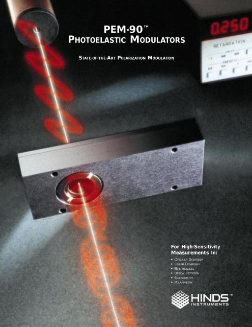
<strong>PEM</strong>-<strong>90</strong> <br />
PHOTOELASTIC MODULATORS<br />
STATE-OF-THE-ART POLARIZATION MODULATION<br />
For High-Sensitivity<br />
Measurements In:<br />
• CIRCULAR DICHROISM<br />
• LINEAR DICHROISM<br />
• BIREFRINGENCE<br />
• OPTICAL ROTATION<br />
• ELLIPSOMETRY<br />
• POLARIMETRY
Founded in 1971, <strong>Hinds</strong> Instruments, Inc. is the world’s leading supplier of photoelastic<br />
modulators. For over 25 years we have been committed to developing this method of polarization<br />
modulation as a basic tool of optical analysis in applications ranging from laboratory<br />
research and development to industrial process monitoring.<br />
The latest result of this ongoing commitment is the new D-Series of the <strong>PEM</strong>-<strong>90</strong>, a<br />
unique photoelastic light modulator system which permits unprecedented levels of sensitivity<br />
in polarized light measurements — to the order of 10 -6 .<br />
Beginning with a single <strong>PEM</strong> model designed for use in the visible spectrum, <strong>Hinds</strong><br />
has developed modulators which extend from the vacuum UV to the mid-IR. Our unique<br />
self-resonating electronic drive design results in a system which is stable, reliable, and easy<br />
to use.<br />
We offer more than a dozen basic <strong>PEM</strong> models for use either as stand-alone<br />
instruments or in integrated systems, as well as several modular accessory instruments that<br />
permit <strong>PEM</strong> users to quickly develop custom configurations.<br />
Custom <strong>PEM</strong> models have been built for use with on-board rocket instruments, laser<br />
microscopes, vacuum chambers, and tokamak fusion experiments, and as standard<br />
components in systems for semiconductor manufacture and process monitoring in a<br />
chemical extraction environment.<br />
Dedicated to serving the scientific and engineering community, our select team of highly<br />
qualified technical professionals has over 65 years combined experience to help you apply<br />
<strong>PEM</strong> polarization modulation technology to your specific application.<br />
<strong>PEM</strong> SYSTEM TESTING AT HINDS INSTRUMENTS IN HILLSBORO, OREGON
COMPACT DISC OPTICAL QUALITY<br />
THE OPTICAL QUALITY OF COMPACT<br />
DISCS HAS BEEN MEASURED USING A<br />
<strong>PEM</strong>-BASED BIREFRINGENCE MEASUR-<br />
ING SYSTEM. THE SYSTEM, SUPPLIED<br />
BY HINDS, SCANS THE FACE OF THE<br />
POLYCARBONATE DISC TO MAP INTER-<br />
NAL STRAIN LEVELS.<br />
The <strong>PEM</strong>-<strong>90</strong> photoelastic modulator is an instrument used for modulating or varying (at a<br />
fixed frequency) the polarization of a beam of light. <strong>Hinds</strong> photoelastic modulators are used<br />
for measurement of circular and linear dichroism, birefringence, optical rotation, and for<br />
ellipsometry, polarimetry, reflection difference spectroscopy, and FTIR double modulation.<br />
The <strong>PEM</strong>-<strong>90</strong> principle of operation is based on the photoelastic effect, in which a<br />
mechanically stressed sample exhibits birefringence proportional to the resulting strain.<br />
Photoelastic modulators are resonant devices, each producing oscillating birefringence at a<br />
fixed frequency in the low frequency ultrasound range (20 kHz to 100 kHz). These factors<br />
result in a number of very useful advantages which are unique to the <strong>PEM</strong> including wide<br />
acceptance angle, large aperture, and high modulation "purity."<br />
In its simplest form the <strong>PEM</strong>-<strong>90</strong> consists of a rectangular bar of a suitable transparent<br />
material (fused silica, for example) attached to a piezoelectric transducer (Figure 1b). The<br />
bar vibrates along its long dimension (Figure 1a) at a frequency determined by the length of<br />
the bar and the speed of a longitudinal sound wave in the optical element material. The<br />
transducer is tuned to the same frequency and is driven by an electronic circuit which<br />
controls the amplitude of vibration. The oscillating birefringence effect is at its maximum at<br />
the center of the fused silica bar.<br />
FIGURE 1. MODULATOR OPTICAL ASSEMBLY FOR MODEL I/FS50.<br />
a) Vibrational motions<br />
b]<br />
Optical Element Aperture Piezoelectric Transducer<br />
To driver circuit<br />
By carefully varying the type, size, and the shape of optical material, and coupling closely<br />
matched drive and control circuits to the <strong>PEM</strong>-<strong>90</strong> optics, we have developed a range of<br />
photoelastic modulators for a variety of applications. In addition to the information provided in<br />
this technical guide, <strong>Hinds</strong> engineers are available for free consultation to help you design<br />
your specific application setup.<br />
3
The <strong>PEM</strong>-<strong>90</strong> line of photoelastic modulators incorporates many design features, including:<br />
• RS-232 interface, allowing computer control and monitoring of all <strong>PEM</strong> functions.<br />
THIN FILM GROWTH<br />
<strong>PEM</strong>-BASED REFLECTANCE DIF-<br />
FERENCE SPECTROMETERS ARE<br />
BEING USED TO MONITOR IN REAL<br />
TIME THE GROWTH OF GALLIUM<br />
ARSENIDE THIN FILMS<br />
(IEEE-488 interface capability is available through a National Instruments converter unit.)<br />
• Digital set-up and display of retardation and source wavelength in user-selectable<br />
units, with automatic adjustment of retardation for varying wavelengths.<br />
• A range of models which spans the spectrum from vacuum UV to mid-IR.<br />
• A retardation function with high sinusoidal accuracy which results in noise-free<br />
modulation or chopping.<br />
• Optional ultra-low residual birefringence optics.<br />
• A documented reputation for stable, trouble-free performance.<br />
Figure 2 details features of the three basic <strong>PEM</strong>-<strong>90</strong> components: the Controller, the<br />
Electronic Head, and the Optical Head.<br />
FIGURE 2. THE <strong>PEM</strong>-<strong>90</strong><br />
PHOTOELASTIC<br />
SYSTEM.<br />
MODULATOR<br />
Selectable display:<br />
modulator frequency,<br />
wavelength of light,<br />
(nanometers, microns,<br />
wavenumber)<br />
Reference signal for<br />
use with lock-in<br />
amplifiers (1f, 2f)<br />
Microprocessor design<br />
provides flexible<br />
retardation control<br />
Wide aperture (1.5 —<br />
3.0 cm for standard<br />
models)<br />
Optical head<br />
orientation<br />
is unrestricted<br />
RS-232 serial interface<br />
to computer<br />
Wide acceptance angle<br />
(+_20˚)<br />
Small size for limited<br />
access or vacuum<br />
chamber use<br />
OPTICAL HEAD<br />
<strong>PEM</strong>-<strong>90</strong><br />
CONTROLLER<br />
Selection of optical<br />
element materials and<br />
designs for different<br />
spectral requirements<br />
Retardation display<br />
Retardation unit<br />
selection (waves,<br />
radians, degrees)<br />
Head interconnect cable<br />
ELECTRONIC HEAD<br />
Key-selectable<br />
retardation:l, l / 2 , l / 4 ,<br />
user defined<br />
Digital interface,<br />
manual selection of<br />
operating parameters<br />
Remote analog signal<br />
control of retardation<br />
Operation error<br />
indicator<br />
Controller drive<br />
signal determines<br />
retardation<br />
Precise frequency<br />
matching<br />
Split head minimizes<br />
optical head size and can<br />
provide magnetic field<br />
compatibility<br />
4
The phenomenon of photoelasticity is the basis for operation of the <strong>PEM</strong>-<strong>90</strong>. If a sample of<br />
transparent solid material is stressed by compression or stretching, the material becomes<br />
birefringent, that is, different linear polarizations of light have slightly different speeds of light<br />
when passing through the material.<br />
<strong>PEM</strong>-<strong>90</strong> Series I modulators use a rectangular shape for the modulator optical element.<br />
In the Model I/FS50, a fused silica bar is made to vibrate with a natural resonant frequency<br />
of about 50 kHz. This vibration is sustained by a quartz piezoelectric transducer attached to<br />
the end of the bar, as shown in Figure 1 (page 3).<br />
At the center of the bar an oscillating birefringence occurs at a frequency of about<br />
50 kHz. The magnitude of the birefringence is controlled electronically with the <strong>PEM</strong>-<strong>90</strong><br />
Controller.<br />
Retardation Effects of Compression and Extension<br />
The effect of the modulator on a linear polarized monochromatic light wave is shown in<br />
Figure 3. The plane of polarization is at 45˚ to the modulator axis before passing through the<br />
modulator. If the optical element is relaxed (Figure 3a) the light passes through with the<br />
polarization unchanged.<br />
a)<br />
E 45 ¡ E y<br />
45 ¡<br />
E x<br />
b)<br />
+ R<br />
c)<br />
- R<br />
If the optical element is compressed, the polarization component parallel to the<br />
modulator axis travels slightly faster than the vertical component. The horizontal component<br />
then “leads” the vertical component after light passes through the modulator (Figure 3b).<br />
If the optical element is stretched, the horizontal component "lags" behind the vertical<br />
component (Figure 3c).<br />
The phase difference between the components at any instant of time is called the<br />
retardation or retardance. The peak retardation is the amplitude of the sinusoidal<br />
retardation as a function of time.<br />
The retardation (in length units) is given by<br />
A(t)=z[n x (t)-n y (t)]<br />
where z is the thickness of the optical element and n x (t) and n y (t) are the instantaneous<br />
values of refractive index along the x and y directions. Common units for retardation include<br />
distance (nanometers, microns), waves (quarter-wave, half-wave), and phase angle (radians,<br />
degrees). As shown in Figure 2 (page 4), the <strong>PEM</strong>-<strong>90</strong> Controller can display retardation in<br />
waves or phase angle.<br />
Quarter-Wave Retardation<br />
An important condition occurs when the peak retardation reaches exactly one-fourth of<br />
the wavelength of light. When this happens, the <strong>PEM</strong> acts as a quarter-wave plate. Figure<br />
4a shows this condition at the instant retardation is at its maximum.
FIGURE 4. QUARTER-WAVE RETARDATION<br />
a)<br />
b)<br />
R =<br />
4<br />
4<br />
0<br />
4<br />
LINEAR<br />
RIGHT<br />
CIRCULAR<br />
LINEAR<br />
LEFT<br />
CIRCULAR<br />
LINEAR<br />
The polarization vector traces a right-handed spiral about the optic axis. Such light<br />
is called "right circularly polarized." For an entire modulator cycle, Figure 4b shows the<br />
VISCOUS FLUID FLOW<br />
STUDIES OF THE FLOW OF<br />
VISCOUS FLUIDS ARE BEING<br />
MADE USING HINDS MODULA-<br />
TORS TO SIMULTANEOUSLY<br />
MEASURE LINEAR DICHROISM,<br />
CIRCULAR DICHROISM AND<br />
BIREFRINGENCE.<br />
retardation vs. time and the polarization states at several points in time. The polarization<br />
oscillates between right circular and left circular, with linear (and elliptical) polarization<br />
states in between.<br />
Half-Wave Retardation<br />
Another important condition occurs when the peak retardation reaches one-half of the<br />
wavelength of the light (Figure 5a). When this happens, the <strong>PEM</strong> acts as a half-wave plate at<br />
the instant of maximum retardation and rotates the plane of polarization by <strong>90</strong>˚.<br />
FIGURE 5. HALF-WAVE RETARDATION<br />
a)<br />
b)<br />
R =<br />
2<br />
2<br />
0<br />
2<br />
+ 45 - 45 + 45 - 45 + 45<br />
RIGHT<br />
CIRCULAR<br />
RIGHT<br />
CIRCULAR<br />
LEFT<br />
CIRCULAR<br />
LEFT<br />
CIRCULAR<br />
Figure 5b shows retardation vs. time for a modulator cycle and indicates polarization<br />
states at several different times during a cycle. At maximum retardation, the polarization<br />
states are linear, rotated by <strong>90</strong>˚.<br />
The half-wave retardation condition is particularly important for calibration of the <strong>PEM</strong>-<strong>90</strong>˚.<br />
Symmetric Optical Element<br />
<strong>PEM</strong>-<strong>90</strong> Series II modulators use a unique symmetric or "octagonal" shape for the<br />
modulator optical element (Figure 6). This utilizes a "two-dimensional" standing wave<br />
which approximately doubles the retardation available with a given drive voltage. Series II<br />
modulators are particularly useful in the infrared spectrum.<br />
FIGURE 6. SYMMETRIC OPTICAL<br />
ASSEMBLY FOR MODEL II/ZS37<br />
6
The <strong>PEM</strong>-<strong>90</strong> may be used in either of two basic modes: as a modulator, to produce polarization<br />
modulation of a light beam, or as an analyzer, to determine the polarization state of a<br />
light beam. More specific applications are discussed in detailed application notes.<br />
Use as a Modulator<br />
The <strong>PEM</strong>-<strong>90</strong> may be used to modulate a beam of light. One frequently used condition of<br />
operation occurs when the peak retardation corresponds to a quarter of the wavelength of<br />
the light being used. This setup is shown in Figure 7.<br />
y<br />
45 ¡ x<br />
As shown in Figure 7, the incoming light is linearly polarized in a plane which is at 45˚<br />
with the long axis of the modulator. The result is light which oscillates between left and right<br />
circularly polarized light, with elliptically polarized light between these extremes. The optical<br />
oscillation frequency is at the modulator frequency (1f). This experimental setup is used for<br />
studies of circular dichroism.<br />
Use as an Analyzer<br />
The <strong>PEM</strong>-<strong>90</strong> may also be used to analyze the state of a polarized beam of light. Figure 8<br />
shows a setup for the measurement of the circular and linear polarization of a beam of light.<br />
y<br />
45 ¡ x<br />
45 ¡<br />
A net circular polarization component will produce an electrical signal in the detector at<br />
the modulator frequency (1f). A net linear polarization component at 45˚ with respect to the<br />
modulator axis will produce an electrical signal in the detector at twice the modulator frequency<br />
(2f). Use of the reference signals from the <strong>PEM</strong>-<strong>90</strong> Controller with lock-in amplifiers<br />
enables the simultaneous measurement of these two polarization components.<br />
Used as a polarimeter, the <strong>PEM</strong>-<strong>90</strong> is capable of detecting polarization components<br />
weaker than 1 part in 10 6 of the total intensity. For complete details on use of the <strong>PEM</strong>-<strong>90</strong><br />
as a polarimeter, consult the Stokes Polarimetry Application Note.
PULSED LASER USE<br />
BY SYNCHRONIZING THE FIRING OF<br />
PULSED LASERS WITH THE<br />
MODULATOR REFERENCE SIGNAL,<br />
HINDS MODULATORS HAVE BEEN<br />
USED FOR TIME-RESOLVED CIRCULAR<br />
DICHROISM AND OTHER FAST PULSE<br />
MEASUREMENTS.<br />
There are several important factors to consider in selecting a <strong>PEM</strong>-<strong>90</strong>. These include the<br />
wavelength of the light to be used, the retardation requirement, use of an antireflection<br />
coating, and the aperture required.<br />
Spectral Range Considerations<br />
The two primary considerations in the selection of a <strong>PEM</strong>-<strong>90</strong> are the spectral region in<br />
which the modulator must operate and the range of retardance required. In general, Series I<br />
modulators are designed for use in UV and visible applications, but they may also be used for<br />
many IR laser diode applications. Model I/CF50 is specifically intended for the vacuum<br />
UV region.<br />
Series II modulators are primarily intended for the near- and mid-IR regions, but some<br />
may be used in the visible spectrum. Consult the specifications table in the Modulator Head<br />
Data Bulletin for details regarding transmission limits and available retardation.<br />
FIGURE 9. SPECTRAL RANGE<br />
ASTRONOMICAL POLARIMETER<br />
HINDS MODULATORS ARE BEING USED<br />
AT NUMEROUS OBSERVATORIES FOR<br />
ASTRONOMICAL POLARIMETRY AT SEN-<br />
SITIVITIES TO 10 -6 AND HIGHER.<br />
EXPERIMENTS HAVE BEEN PER-<br />
FORMED IN THE NEAR UV, THE VISI-<br />
BLE, AND THE IR SPECTRUM OUT TO<br />
10 MICRONS.<br />
Retardation Requirements<br />
A <strong>PEM</strong>-<strong>90</strong> intended for both half-wave and quarter-wave applications should be capable<br />
of providing half-wave retardation throughout the spectral region of interest. Standard linear<br />
dichroism setups require half-wave operation, and it should be possible to achieve half-wave<br />
operation at any wavelength where calibration of the retardation is required.<br />
Many modulator applications require only quarter-wave retardation. These include<br />
circular dichroism, optical rotation, polarimetry, birefringence, and amplitude modulation<br />
or chopping.<br />
Some advanced techniques use a third modulator setting: the first retardation setting<br />
at which the Bessel Function J O (A O )=O. This occurs at a retardation setting of A O =2.405<br />
radians or 0.383 waves. For this setting, the average DC signal may be used for signal<br />
normalization.<br />
8
Optical Considerations<br />
Aperture. <strong>Hinds</strong> can supply custom modulators with special size apertures. For a given<br />
optical element material, the aperture (and optical assembly size) is inversely proportional to<br />
the operating frequency. Standard apertures range from 1.5 to 3.0 cm.<br />
Use with lasers. Laser light sources are monochromatic and have high spatial coherence,<br />
which can lead to undesirable interference effects. Reflections between the optical element<br />
surfaces may cause spurious detector signals at the fundamental and other harmonic<br />
frequencies. Use of antireflective coatings, tilting the modulator, or a special patented “noninterference”<br />
option which deflects internally reflected beams can reduce or eliminate this<br />
problem. Contact <strong>Hinds</strong> engineers for assistance with laser applications.<br />
Antireflection coatings. Antireflection coatings may be used to increase the throughput<br />
of light through the modulator, to reduce the interference effects, and to reduce the fraction<br />
of light which passes through the modulator at an undesired peak retardation. In particular,<br />
zinc selenide and silicon modulators benefit from antireflection coatings because of their high<br />
indices of refraction. Note: An antireflection coating will significantly reduce the usefulness of<br />
the modulator outside the spectral band of the coating.<br />
Detector Considerations<br />
The detector and its associated electronics should receive careful consideration. If<br />
oscilloscope calibration of the system is required, the detector and amplifying electronics<br />
should have a frequency bandwidth several times the fundamental modulator frequency.<br />
Many applications require that a low-pass DC signal component be derived from the detector<br />
signal. For many applications the lock-in amplifier should be able to operate at the second<br />
harmonic of the modulator frequency.<br />
<strong>Hinds</strong> offers several modular accessories including a Photodiode/Preamplifier Assembly<br />
for detecting modulated light signals. This detector module is specially designed for the<br />
requirements of systems which use <strong>PEM</strong>-<strong>90</strong> photoelastic modulators.<br />
Modular Components and Engineering Support<br />
The RS232 serial interface is standard with the <strong>PEM</strong>-<strong>90</strong> controller. If IEEE-488<br />
operation is desired, this may be obtained using a National Instruments Model GPIB-<br />
232CV-A converter. A signal conditioner is available which derives from the detector signal a<br />
low-pass (DC) signal and a wide-band AC signal.<br />
Please call to discuss your application and experimental setup with our engineers before<br />
ordering. Our toll-free number in the United<br />
States and Canada is 1 800 688-4463. (Find our<br />
address and other contact information on the<br />
back cover.)<br />
ON-LINE PROCESS MONITOR<br />
<strong>PEM</strong>-<strong>90</strong> Photoelastic Modulator Systems,<br />
for state-of-the-art polarization modulation.<br />
A CHEMICAL EXTRACTION PROCESS<br />
USES AN ON-LINE <strong>PEM</strong>-BASED CIRCU-<br />
LAR DICHROISM MONITOR, DEVELOPED<br />
AND MANUFACTURED BY HINDS, TO<br />
MEASURE SOLUTION CONCENTRATIONS<br />
AS LOW AS 1 PPM FOR PROCESS<br />
END-POINT DETERMINATION.<br />
9<br />
National Instruments is a trademark of National Instruments Corporation
INTERNATIONAL REPRESENTATIVES<br />
EUROPE<br />
FRANCE:<br />
EQUIPMENTS SCIENTIFIQUES SA<br />
127 RUE DE BUZENVAL, B.P. N˚ 26<br />
92380 GARCHES, FRANCE<br />
TELEPHONE 33 14 7959<strong>90</strong>0 FAX 33 14 7011622<br />
E-MAIL: opt@es-france.com<br />
GERMANY:<br />
NUCLETRON VERTRIEBS GMBH<br />
GAERTNERSTRASSE 60, POSTFACH 50 01 80<br />
8000 MUNICH 50, GERMANY<br />
TELEPHONE 49 89 14 <strong>90</strong> 02 20 FAX 49 89 14 <strong>90</strong> 02 11<br />
E-MAIL: nucletron@compuserve.com<br />
ITALY:<br />
GIOTTO HIGH TECHNOLOGY<br />
GALLERIA SPAGNA 25<br />
I-35127 PADOVA, ITALY<br />
TELEPHONE 39 49 870 1542 FAX 39 49 870 3349<br />
NETHERLANDS:<br />
FAIRLIGHT BV.<br />
P.O. BOX 81037<br />
3009 GA ROTTERDAM, NETHERLANDS<br />
TELEPHONE 31 10 420 6444 FAX 31 10 420 6511<br />
E-MAIL: Fairlight@LOT-Oriel.com<br />
SPAIN:<br />
INSTRUMATIC ESPAÑOLA, S.A.<br />
AVDA, BRASIL, 17-11B<br />
28020 MADRID, SPAIN<br />
TELEPHONE 34 91 555 81 12 FAX 34 91 597 10 77<br />
E-MAIL: instrumatic@instrumatic.es<br />
WEB SITE: www.intstrumatic.es<br />
SWITZERLAND:<br />
GMP SA<br />
19, AV DES BAUMETTES / CP<br />
CH-1020 RENENS 1, SWITZERLAND<br />
TELEPHONE 41 21 634 8181 FAX 41 21 635 3295<br />
E-MAIL: gmp@gmp.ch<br />
UNITED KINGDOM:<br />
THE RODITI INTERNATIONAL CORP., LTD.<br />
CARRINGTON HOUSE, 130 REGENT STREET<br />
LONDON W1R 6BR, UNITED KINGDOM<br />
TELEPHONE 44 171 439 43<strong>90</strong> FAX 44 171 434 0896<br />
E-MAIL: caw@roditi.co.uk<br />
WEB SITE: www.roditi.co.uk<br />
ASIA<br />
INDIA:<br />
KLB INSTRUMENTS CO. PVT. LTD.<br />
1E/17 JHANDEWALAN EXTN.<br />
POST BOX NO 5726<br />
NEW DELHI 110 055, INDIA<br />
TELEPHONE 91 11 3541718 FAX 91 11 3541720<br />
E-MAIL: klbninst@del2.vsnl.net.in<br />
JAPAN:<br />
TOKYO INSTRUMENTS, INC.<br />
T.I. BUILDING, 6-18-14 NISHIKASAI<br />
EDOGAWA-KU, TOKYO 134, JAPAN<br />
TELEPHONE 81 3 3686 4711 FAX 81 3 3686 0831<br />
E-MAIL: ac2s-srg@j.asahi-net.or.jp<br />
WEB SITE: www.kagaku.com/t-inst<br />
KOREA:<br />
HK INTERNATIONAL CORPORATION<br />
ROOM 202, CORE BUILDING, #1543-6 SEOCHO 3-DONG<br />
SEOUCHO-KU, SEOUL, KOREA<br />
TELEPHONE 822 587 4366 FAX 822 587 4369<br />
E-MAIL: hkip@unitel.co.kr<br />
TAIWAN:<br />
UNICE E-O SERVICES, INC.<br />
NO 25 CHUNG-MING ROAD<br />
CHUNG LI, TAIWAN ROC<br />
TELEPHONE 886 34 91 2245 FAX 886 34 91 2243<br />
E-MAIL: unice1@ms4.hinet.net<br />
SOUTH AMERICA<br />
ARGENTINA:<br />
IOTA SA<br />
AVELLANDENA 1567<br />
BUENOS AIRES 1406, ARGENTINA<br />
TELEPHONE 54 1 432 8520 FAX 54 1 432 8459<br />
E-MAIL: gcetera@iota.com.ar<br />
MIDDLE EAST<br />
ISRAEL:<br />
LAHAT TECHNOLOGIES, LTD.<br />
P.O. BOX 1725<br />
RAMAT HASHARON 47166, ISREAL<br />
TELEPHONE 972 3 5472741 FAX 972 3 5472742<br />
E-MAIL: davidp@lahat.co.il<br />
WEB SITE: www.lahat.co.il<br />
HINDS INSTRUMENTS, INC.<br />
3175 NW ALOCLEK DRIVE<br />
HILLSBORO, OR 97124-7135<br />
PHONE: 503/6<strong>90</strong>-2000<br />
FAX: 503/6<strong>90</strong>-3000<br />
TOLL FREE: 1 800 688-4463<br />
COPYRIGHT © 1991, 1994, 1995, 1999<br />
HINDS INSTRUMENTS, INC.<br />
ALL RIGHTS RESERVED<br />
MANUFACTURED IN USA UNDER PATENTS & PATENTS PENDING.<br />
PRINTED IN USA. 5M/10-95