Helium Catalyzed DD Fusion in a Levitated Dipole - Plasma Science ...
Helium Catalyzed DD Fusion in a Levitated Dipole - Plasma Science ...
Helium Catalyzed DD Fusion in a Levitated Dipole - Plasma Science ...

Create successful ePaper yourself
Turn your PDF publications into a flip-book with our unique Google optimized e-Paper software.
<strong>Helium</strong> <strong>Catalyzed</strong> D-D <strong>Fusion</strong> <strong>in</strong> a <strong>Levitated</strong> <strong>Dipole</strong><br />
J. Kesner, D.T. Garnier † , A. Hansen † , M. Mauel † , L. Bromberg<br />
<strong>Plasma</strong> <strong>Science</strong> and <strong>Fusion</strong> Center, MIT, Cambridge, Mass. 02139<br />
†<br />
Dept. Applied Physics, Columbia University, New York, N.Y. 10027<br />
PACS 28.52.-S<br />
Abstract<br />
<strong>Fusion</strong> research has focused on the goal of a fusion power source that utilizes<br />
deuterium and tritium (D-T) because the reaction rate is relatively large.<br />
<strong>Fusion</strong> reactors based on the deuterium-deuterium (D-D) reaction however,<br />
might be superior to D-T based reactors <strong>in</strong> so far as they m<strong>in</strong>imize the power<br />
produced <strong>in</strong> neutrons and do not requires the breed<strong>in</strong>g of tritium. We explore<br />
an alternative D-D based fuel cycle and show that a levitated dipole may be<br />
uniquely suited for this application. We f<strong>in</strong>d that a dipole based D-D power<br />
source can potentially provide a substantially better utilization of magnetic<br />
field energy with a comparable mass power density to a D-T based tokamak<br />
power source.<br />
1
1 Introduction<br />
Dur<strong>in</strong>g the past several decades the focus of controlled fusion research has<br />
been the development of magnetic traps that are appropriate for ignit<strong>in</strong>g and<br />
susta<strong>in</strong><strong>in</strong>g a controlled fusion burn. The fusion cross section and reaction rate<br />
coefficient is significantly larger for deuterium-tritium (D-T) than any other<br />
reaction which makes a D-T based power source very much easier to ignite<br />
and burn than any other fusion reactor. The D-T rate coefficient is two orders<br />
of magnitude larger than the rate coefficient for Deuterium- 3 <strong>Helium</strong> (D- 3 He)<br />
reaction or for the deuterium-deuterium (D-D) reaction. The tokamak has<br />
proven to be the most successful device for produc<strong>in</strong>g near-ignition plasma<br />
conditions and much of the research <strong>in</strong> this area has focused on tokamaks.<br />
For these reasons it seems likely that the first self-susta<strong>in</strong><strong>in</strong>g fusion reaction<br />
will utilize D-T fuel <strong>in</strong> a tokamak.<br />
In this article we propose a different approach for a fusion power source,<br />
based on an alternative fuel cycle which we call “helium catalyzed D-D”.<br />
The D-D cycle is difficult <strong>in</strong> a traditional fusion conf<strong>in</strong>ement device such as a<br />
tokamak because good energy conf<strong>in</strong>ement is accompanied by good particle<br />
conf<strong>in</strong>ement which would lead to a build up of ash <strong>in</strong> the discharge [1].<br />
Recently there has been a develop<strong>in</strong>g <strong>in</strong>terest <strong>in</strong> the conf<strong>in</strong>ement of a plasma<br />
<strong>in</strong> a levitated dipole configuration [2, 3] and a levitated dipole experiment<br />
known as LDX is presently under construction [4]. A dipole may have the<br />
unique capability of produc<strong>in</strong>g excellent energy conf<strong>in</strong>ement accompanied by<br />
low particle conf<strong>in</strong>ement. We will explore the application of a levitated dipole<br />
as a D-D power source.<br />
The basis for this behavior is the MHD prediction that a dipole conf<strong>in</strong>ed<br />
plasma rema<strong>in</strong>s stable below a critical pressure gradient. At marg<strong>in</strong>al stability,<br />
which occurs when pU γ = constant with p the plasma pressure, U the<br />
differential flux tube volume U ≡ ∮ dl/B and γ = 5/3 an exchange of flux<br />
tubes does not modify the pressure profile [5, 6]. When flux tubes exchange<br />
adiabatically the plasma cools as it moves <strong>in</strong>to lower fields and heats as it<br />
2
moves <strong>in</strong>to higher fields and at marg<strong>in</strong>ality it rema<strong>in</strong>s <strong>in</strong> thermal equilibrium<br />
with the local pressure as it circulates. Non-l<strong>in</strong>ear studies <strong>in</strong>dicate that large<br />
scale convective cells will form when the MHD stability limit is violated,<br />
which result <strong>in</strong> rapid circulation of plasma between the hot core and the<br />
cooler edge [7, 8, 9]. In addition there is sufficient energy transport to keep<br />
the plasma pressure profile close to the marg<strong>in</strong>al stability state.<br />
When a dipole conf<strong>in</strong>ed plasma ignites it will heat up to the <strong>in</strong>terchange<br />
stability limit giv<strong>in</strong>g rise to convective flows. Once it ignites we would expect<br />
the pressure gradient to violate the <strong>in</strong>terchange stability criterion which will<br />
give rise to convective cells that will circulate particles between the core and<br />
edge region. The convective cells also unload excess heat so as to ma<strong>in</strong>ta<strong>in</strong><br />
a pressure profile that is close to the marg<strong>in</strong>al state.<br />
Theoretical studies predict that a levitated dipole can support high beta<br />
plasmas and this translates <strong>in</strong>to excellent magnetic field utilization. Studies<br />
also predict that the conf<strong>in</strong>ed plasma can be stable to low frequency (drift<br />
wave) modes and therefore we might expect that the energy conf<strong>in</strong>ement will<br />
rema<strong>in</strong> close to the classical value. Additionally a levitated dipole device<br />
would be <strong>in</strong>tr<strong>in</strong>sically steady state and extract power as surface heat<strong>in</strong>g,<br />
permitt<strong>in</strong>g a th<strong>in</strong> walled vacuum vessel and elim<strong>in</strong>at<strong>in</strong>g the need for a massive<br />
neutron shield.<br />
Although the large rate coefficient associated with the D-T reaction is<br />
appeal<strong>in</strong>g to fusion researchers, burn<strong>in</strong>g D-T entails serious difficulties. As<br />
tritium does not occur naturally it must be bred (us<strong>in</strong>g the n( 6 Li, T )α reaction)<br />
and provid<strong>in</strong>g a sufficient breed<strong>in</strong>g ratio (> 1) poses a serious challenge<br />
for plant design [10]. In addition, tritium is bioactive and is subject to radioactive<br />
decay and so tritium handl<strong>in</strong>g complicates the operation of such a<br />
device. A second difficulty is posed by the production of 14.1 MeV neutrons,<br />
the product of the D-T fusion reaction. Energetic neutrons will degrade,<br />
damage and activate the structural materials of the reactor. Furthermore,<br />
the large mass that is required to stop energetic neutrons leads to the re-<br />
3
quirement that a massive blanket and shield must surround the fus<strong>in</strong>g D-T<br />
plasma and be <strong>in</strong>ternal to the superconduct<strong>in</strong>g toroidal field coils.<br />
The D- 3 He reaction elim<strong>in</strong>ates most of the energetic neutron generation.<br />
The use of a dipole for burn<strong>in</strong>g D- 3 He as both a power source [3] and for<br />
propulsion [15] has been exam<strong>in</strong>ed. However, as with tritium, 3 He is not<br />
abundant on the earth. It has been po<strong>in</strong>ted out that it can be m<strong>in</strong>ed on the<br />
moon [13] or on a longer time scale be obta<strong>in</strong>ed from Jupiter [14] but develop<strong>in</strong>g<br />
the required technology for non-terrestrial m<strong>in</strong><strong>in</strong>g presents a daunt<strong>in</strong>g<br />
task.<br />
The D-D reaction is perhaps the most <strong>in</strong>terest<strong>in</strong>g from the po<strong>in</strong>t of view<br />
of elim<strong>in</strong>at<strong>in</strong>g both the tritium and the energetic neutron problems. However<br />
the relatively small fusion cross section has made this approach problematical.<br />
A direct consequence of the low reactivity is that the buildup of ash <strong>in</strong><br />
the fus<strong>in</strong>g plasma can preclude ignition <strong>in</strong> a tokamak-like device [1].<br />
In this study we show that a levitated dipole device may be ideally suited<br />
for a D-D based fusion power source. Section 2 reviews fusion reaction considerations<br />
and dipole physics. In Sec. 3 we present as a conceptual dipole<br />
configuration that can serve as an example of the plasma and plant parameters<br />
considered. Section 4 presents the conceptual configuration for a small<br />
D-T based ignition experiment that might serve as a crucial test of the approach<br />
and Sec. 5 presents a discussion of this approach. Conclusions are<br />
presented <strong>in</strong> Sec. 6.<br />
2 D-D <strong>Fusion</strong><br />
The most important reactions for controlled nuclear fusion are as follows:<br />
D + T → 4 He(3.5 MeV ) + n(14.1 MeV )<br />
D + 3 He → 4 He(3.6 MeV ) + p(14.7 MeV )<br />
D + D 50%<br />
−→ 3 He(0.82 MeV ) + n(2.45 MeV )<br />
D + D 50%<br />
−→ T (1.01 MeV ) + p(3.02 MeV ) (1)<br />
4
D-T and D- 3 He require difficult-to-obta<strong>in</strong> fuels whereas the D-D cycle utilizes<br />
only deuterium for fuel, which can be easily extracted from sea water.<br />
Unfortunately the low fusion reaction rate requires exceptionally good conf<strong>in</strong>ement<br />
for ignition. Furthermore the particle to energy conf<strong>in</strong>ement time<br />
ratio, τp ∗ /τ e is a sensitive parameter for the ignition of a D-D system and rema<strong>in</strong>s<br />
relatively constant <strong>in</strong> currently studied systems because both particle<br />
and energy conf<strong>in</strong>ement derive from the same underly<strong>in</strong>g process of microturbulence.<br />
Studies show [1] that ignition requires τp ∗ /τ E < 2 whereas tokamak<br />
experiments generally observe τp ∗ /τ E > 5. Ignition of D-D fuel therefore<br />
requires a system that can decouple the particle and energy conf<strong>in</strong>ement.<br />
This requirement suggests the use of a closed-field-l<strong>in</strong>e system like a dipole<br />
<strong>in</strong> which large scale convective cells can rapidly convect particles out of the<br />
fus<strong>in</strong>g plasma core. (In a properly designed system the plasma is quiescent<br />
up to the po<strong>in</strong>t of ignition. Thereafter the large <strong>in</strong>ternal power production<br />
would give rise to <strong>in</strong>stability that leads to the formation of convective cells<br />
which would serve to ma<strong>in</strong>ta<strong>in</strong> the pressure profile at close to a critical value.)<br />
Referr<strong>in</strong>g back to the fusion reactions shown <strong>in</strong> Eq. (1) there are two<br />
equally likely D-D fusion reactions. The first reaction produces a 3 He whereas<br />
the second produces a triton. The 3 He will fuse with the background deuterium.<br />
Permitt<strong>in</strong>g the tritium to fuse leads to the ”catalyzed <strong>DD</strong>” fuel<br />
cycle. However because the D-T reaction would produce an energetic (14.1<br />
MeV) neutron that would be difficult to prevent from enter<strong>in</strong>g and heat<strong>in</strong>g<br />
an <strong>in</strong>ternal coil, we propose to remove the triton before a substantial fraction<br />
can fuse and replace it with the 3 He tritium decay product. This leads to the<br />
production of 22 MeV of energy per D-D fusion reaction. This fusion cycle<br />
has been discussed <strong>in</strong> References [11, 12] and will be referred to as “<strong>Helium</strong><br />
catalyzed D-D” fusion.<br />
The Lawson criterion is obta<strong>in</strong>ed by balanc<strong>in</strong>g the fusion power that is<br />
produced <strong>in</strong> energetic ions (which can self-heat the plasma) with Bremsstrahlung<br />
radiation and with energy transport losses characterized by a conf<strong>in</strong>ement<br />
5
time, τ E . We will assume that we can extract the tritium produced <strong>in</strong> the<br />
D-D reaction and re<strong>in</strong>ject the 3 He decay product <strong>in</strong>to the plasma. In equilibrium<br />
the deuterium density is determ<strong>in</strong>ed from the follow<strong>in</strong>g balance:<br />
d n D<br />
dt<br />
= 0 = S D − n 2 D〈σv〉 <strong>DD</strong> − n D n T 〈σv〉 DT − n D<br />
τ p<br />
. (2)<br />
with S D the deuterium source and τ p the particle conf<strong>in</strong>ement time. For<br />
simplicity we will assume that all ions have a similar conf<strong>in</strong>ement time and<br />
later discuss the implications of selectively remov<strong>in</strong>g tritium. The 3 He density<br />
is then determ<strong>in</strong>ed by a balance of production of 3 He [1], i.e.<br />
d n He3<br />
dt<br />
= 0 = 1 4 n2 D〈σv〉 <strong>DD</strong> + n T<br />
τ p<br />
− n He3 n D 〈σv〉 DHe3 . (3)<br />
The tritium density is obta<strong>in</strong>ed from the D-T rate equation, i.e.<br />
d n T<br />
dt<br />
= 0 = 1 4 n2 D〈σv〉 <strong>DD</strong> − n D n T 〈σv〉 DT − n T<br />
τ p<br />
. (4)<br />
These equations will determ<strong>in</strong>e the fraction of the non-deuterium ions, which<br />
are found to be low compared with the deuterium density. F<strong>in</strong>ally the power<br />
balance will yield;<br />
3<br />
2 n eT e + 3 2 (n T + n D + n He3 )T i<br />
τ E<br />
+ n 2 eP Brem (T e )<br />
= 1 2 n2 D〈σv〉 <strong>DD</strong> E <strong>DD</strong> + n D n He3 〈σv〉 DHe3 E DHe3 + n D n T 〈σv〉 DT E DT . (5)<br />
Additionally neutrality requires n D + n T + 2n He = n e . The E αα notation<br />
<strong>in</strong> Eq. (5) represents the energy produced <strong>in</strong> the respective fusion reactions.<br />
Sett<strong>in</strong>g T e = T i , assum<strong>in</strong>g a fixed ratio τ E /τ p and apply<strong>in</strong>g quasi-neutrality<br />
(n e = n D + n T + 2n He3 ) we can solve for the equilibrium fraction of each<br />
species and formulate the Lawson criterion, n e T τ E vs T. Fig. 1 compares<br />
the Lawson criterion for <strong>Helium</strong> catalyzed D-D fusion for τ E /τ p = 5 with<br />
the fusion reactions of Eq.(1). (Later we will see that τ E /τ p can greatly<br />
exceed this value.)<br />
For operation at an ion temperatures of 40 KeV the<br />
He-catalyzed-<strong>DD</strong> cycle presents a favorably low requirement on nτ E T .<br />
6
The energetic triton produced <strong>in</strong> the primary D-D reaction, however, will<br />
slow down and thermalize before it can be convected out to the plasma edge<br />
and removed. We can estimate the beam-plasma fusion rate for an energetic<br />
triton slow<strong>in</strong>g down <strong>in</strong> a thermal deuterium plasma. Us<strong>in</strong>g the energy loss<br />
rate from Ref. [16] and the D-T fusion cross-sections from Ref. [17] we can<br />
obta<strong>in</strong> the fusion probability for a 1 MeV triton <strong>in</strong> a warm deuterium plasma.<br />
The fusion probability as a function of plasma temperature (T e = T i ) is shown<br />
<strong>in</strong> Fig. 2. For a 40 KeV deuterium plasma we f<strong>in</strong>d that approximately ≈ 7%<br />
of the tritons fuse as they slow down.<br />
2.1 Review of <strong>Dipole</strong> Physics<br />
The dipole fusion concept was motivated by satellite observations of planetary<br />
magnetospheres that show centrally peaked plasma pressure profiles<br />
form<strong>in</strong>g naturally when the solar w<strong>in</strong>d drives plasma circulation and heat<strong>in</strong>g<br />
[2]. In the magnetosphere the primary loss for bulk plasma is flow along<br />
field l<strong>in</strong>es <strong>in</strong>to the planetary poles and as a fusion concept we want to elim<strong>in</strong>ate<br />
this loss by utiliz<strong>in</strong>g a levitated float<strong>in</strong>g coil to ma<strong>in</strong>ta<strong>in</strong> the magnetic<br />
field. The field l<strong>in</strong>es close around the coil and we will assume that a high<br />
beta plasma surrounds the r<strong>in</strong>g. This plasma may be characterized as be<strong>in</strong>g<br />
divided <strong>in</strong>to two regions: In the “<strong>in</strong>ner” region, R c < R < R p with R the flux<br />
tube radius on the outer mid-plane, R c the outer radius of the float<strong>in</strong>g coil<br />
cryostat and R p the radius at the pressure peak. In this region the plasma<br />
pressure is close to zero at the r<strong>in</strong>g, p(R c ) ∼ 0 and rises <strong>in</strong> a region of “good<br />
curvature” to a peak value at R = R p . In the “outer” region R p < R < R w<br />
with R w the mid-plane wall radius the pressure falls <strong>in</strong> a region of “bad curvature”<br />
from its peak value to its value on the separatrix as <strong>in</strong>dicated <strong>in</strong><br />
Fig. 3.<br />
The equilibrium of high beta plasmas follows from the Grad-Shafranov<br />
equation and it has been shown that dipole equilibrium can be obta<strong>in</strong>ed<br />
at all beta values [19, 20].<br />
The plasma <strong>in</strong> a closed field l<strong>in</strong>e system can<br />
7
e stabilized <strong>in</strong> the outer region of so-called “bad curvature” by plasma<br />
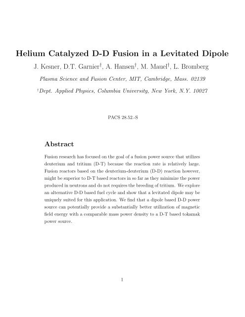
compressibility [5, 6]. Figure 4 shows an equilibrium that we shall exam<strong>in</strong>e<br />
for a model reactor. In Fig. 4 we have chosen R c =9.7 m, R p =10.15 m,<br />
R w =30 m and an edge plasma pressure p(R w )=500 Pa which yields a peak<br />
β value of β(R p )=3.1.<br />
In magnetohydrodynamic (MHD) theory the stability of <strong>in</strong>terchange modes<br />
limits the pressure gradient to a value:<br />
d ≡ − dln p<br />
dln U < γ (6)<br />
with U = ∮ dl/B and γ is the ratio of specific heats (γ ≡ c p /c v = 5/3 is<br />
the ratio of specific heats <strong>in</strong> three-dimensional systems at constant pressure<br />
and volume). It has been shown that the <strong>in</strong>terchange criterion is valid for<br />
marg<strong>in</strong>al stability at all beta values and that balloon<strong>in</strong>g modes do not limit<br />
stability [18, 19, 20]. Recent work utiliz<strong>in</strong>g resistive MHD <strong>in</strong>dicates that the<br />
usual fractional power resistive modes (γ ∝ η 1/3 ) do not appear <strong>in</strong> a dipole<br />
although a weak residual resistive mode may be present that has a growth<br />
rate proportional to resistivity, γ R ∝ η [21].<br />
When the pressure profile exceeds the flute mode stability limit it has been<br />
predicted that the system will develop large-scale convective cells which can<br />
lead to non-local transport [22, 23, 24, 25, 26]. The non-l<strong>in</strong>ear evolution of a<br />
hard-core z-p<strong>in</strong>ch (which is a large aspect ratio approximation for a dipole)<br />
has recently been studied by Pastukhov [7, 8, 27]. His simulations <strong>in</strong>dicate<br />
that when the <strong>in</strong>terchange stability condition (Eq. 6) is violated, large scale<br />
convective cells will form that lead to sufficiently large non-local energy transport<br />
so as to ma<strong>in</strong>ta<strong>in</strong> the system at close to the marg<strong>in</strong>al pressure profile.<br />
Additionally he shows that these cells will rapidly convect particles that emanate<br />
from a particle source at the plasma edge <strong>in</strong>to the core, lead<strong>in</strong>g to a<br />
n e ∝ 1/U density profile [28] <strong>in</strong> the outer dipole region.<br />
Equation (6) <strong>in</strong>dicates that <strong>in</strong> a bad curvature region the pressure must<br />
decay relatively slowly and this implies that ignition <strong>in</strong> a dipole requires a<br />
8
small plasma <strong>in</strong> a relatively large vacuum chamber. For a sufficiently large<br />
dipole power source, the conf<strong>in</strong>ed plasma will rema<strong>in</strong> MHD stable as it is<br />
heated to ignition. Once it ignites we would expect the pressure gradient to<br />
violate the <strong>in</strong>terchange stability criterion which will give rise to convective<br />
cells that will circulate particles between the core and edge region.<br />
The<br />
convective flow speed has been shown to be ɛc s with c s the sound speed and<br />
ɛ ∼ 0.01 is a small scal<strong>in</strong>g parameter, ɛ ≈ (χ/ac s ) 1/3 with χ the thermal<br />
diffusivity and a the plasma half width [8]. For the electron temperature<br />
T e ∼ 30 KeV and a ∼ 10 m the circulation time of the cells is milliseconds<br />
while we will see that the energy conf<strong>in</strong>ement time is seconds. The particle<br />
conf<strong>in</strong>ement time is a fraction of the energy conf<strong>in</strong>ement time s<strong>in</strong>ce particles<br />
need only to diffuse the small distance between the outer cells and the plasma<br />
edge and tritium can be actively removed from the outer region. Thus tritium<br />
and ash can be removed <strong>in</strong> a time that is a small fraction of the energy<br />
conf<strong>in</strong>ement time.<br />
The convective cells also unload excess heat so as to<br />
ma<strong>in</strong>ta<strong>in</strong> a pressure profile that is close to the marg<strong>in</strong>al state.<br />
For a closed-field l<strong>in</strong>e system the MHD stability requirement (Eq.( 6)) is<br />
<strong>in</strong>tr<strong>in</strong>sically related to the criteria for the stability of drift waves. If we def<strong>in</strong>e<br />
the follow<strong>in</strong>g frequencies:<br />
and<br />
ˆω mhd<br />
d<br />
≡ 2c<br />
e<br />
ˆω ∗p ≡ ⃗ b × ⃗ k · ∇p<br />
Ω i m i n i<br />
(7)<br />
Rk θ T<br />
1 + γ〈β〉/2<br />
∮ dl κ/RB<br />
2<br />
∮ dl/B<br />
(8)<br />
with R the cyl<strong>in</strong>drical radial coord<strong>in</strong>ate, κ the field l<strong>in</strong>e curvature, k θ the<br />
azimuthal part of the perpendicular wave number (k 2 ⊥ = k 2 θ + k 2 R) and k θ R =<br />
m ≫ 1, one can show that d def<strong>in</strong>ed <strong>in</strong> Eq. (6) is equal to d = ˆω ∗p /ˆω mhd<br />
d .<br />
Therefore the MHD stability requirement, d ≤ γ, (Eq. (6)) can be written<br />
as:<br />
ˆω ∗p = ω ∗i (1 + η) ≤ γ ˆω mhd<br />
d . (9)<br />
9
with ω ∗j the diamagnetic drift frequency, ω ∗j = T j<br />
⃗ k × ⃗ b · ∇n0 /(n j m j Ω j ) and<br />
η = dln T/dln n.<br />
It has been shown that the outer region of the dipole can be subject to an<br />
“entropy mode” <strong>in</strong>stability when η < 2/3 [29, 30, 31]. This result holds <strong>in</strong> all<br />
regimes of collisionality [30] and at arbitrary beta [32]. In the <strong>in</strong>ner (goodcurvature)<br />
region the temperature and pressure will rise mov<strong>in</strong>g away from<br />
the coil but the density will fall (assum<strong>in</strong>g complete recycle at the <strong>in</strong>ternal<br />
coil) and therefore η < −1. In this regime <strong>in</strong>stability of the entropy mode<br />
is possible[31]. Ultimately the level of plasma energy transported towards<br />
the r<strong>in</strong>g will be determ<strong>in</strong>ed experimentally and this is one of the goals of the<br />
LDX experiment [4].<br />
3 <strong>Dipole</strong> Based D-D Power Source<br />
We will now consider a dipole based D-D power source. A levitated dipole is<br />
<strong>in</strong>tr<strong>in</strong>sically steady state and leads to a relatively simple reactor configuration.<br />
It requires only two large coils, the float<strong>in</strong>g coil and the levitation coil<br />
that holds up the float<strong>in</strong>g coil, either from above or below. A third coil may<br />
be used to <strong>in</strong>ductively charge the float<strong>in</strong>g coil and small shap<strong>in</strong>g coils may<br />
also be utilized as is the case <strong>in</strong> the LDX experiment [4]. The coils are not<br />
<strong>in</strong>ter-lock<strong>in</strong>g so that replacement of the float<strong>in</strong>g coil would be a relatively<br />
simple procedure.<br />
A dipole fusion source would consist of a relatively small r<strong>in</strong>g <strong>in</strong> a large<br />
vacuum chamber. In the He-catalyzed D-D reaction approximately 94% of<br />
the power is generated <strong>in</strong> energetic ions and a substantial fraction of the<br />
plasma energy leaves the plasma as Bremsstrahlung radiation. The surface<br />
power load<strong>in</strong>g is relatively low (< 0.1 MW/m 2 ) and suggestive of a relatively<br />
th<strong>in</strong>-wall vessel conta<strong>in</strong><strong>in</strong>g a slowly flow<strong>in</strong>g coolant.<br />
The <strong>in</strong>ternal float<strong>in</strong>g coil will operate with a high outer surface temperature<br />
(> 1600 0 K) so as to radiate away all of the surface and neutron heat<strong>in</strong>g<br />
10
via black body radiation (assum<strong>in</strong>g an emissivity≈1). In addition, we envision<br />
that the float<strong>in</strong>g coil will have <strong>in</strong>ternal refrigerators that will pump<br />
to the surface the heat that is deposited directly <strong>in</strong>to the superconduct<strong>in</strong>g<br />
coil via volumetric neutron heat<strong>in</strong>g. We imag<strong>in</strong>e that the coil will utilize<br />
a high temperature ceramic superconductor such as BSCCO or YBCO [33]<br />
capable of operat<strong>in</strong>g at a temperature above 50 0 K. In the neutronics and<br />
thermodynamics studies presented below we will model the coil mass makeup<br />
to be similar to BSCCO and assume an operat<strong>in</strong>g temperature of 70 0 K.<br />
Another promis<strong>in</strong>g superconduct<strong>in</strong>g material is magnesium diboride, which<br />
may operate at temperatures of up to 30 0 K.<br />
For D-D ignition, the peak pressure p(R p ), must exceed ∼ 5 MPa. The<br />
power source characteristics are shown <strong>in</strong> Table 1 for a float<strong>in</strong>g coil that<br />
carries I coil =36 MA with a peak field at the conductor of 30 T (Source A)<br />
and for a less aggressive case (same coil dimensions) with I coil =25 MA. (The<br />
less aggressive case, Source B, reduces the magnetic hoop stress by 50% to<br />
a level which is more compatible with todays magnetic technology.)<br />
Eq. (6) the peak-to-edge pressure ratio is:<br />
From<br />
p(R p )<br />
p(R w ) = ( (<br />
∮ dl/B)wall<br />
( ∮ dl/B) Rp<br />
) γ<br />
(10)<br />
For a given size vacuum chamber we have attempted to maximize the fusion<br />
power produced. We have chosen a high aspect ratio coil because, at high<br />
β, and for a fixed size vacuum chamber, the <strong>in</strong>creased mid-plane field <strong>in</strong> a<br />
high aspect ratio coil more than makes up for the reduced distance to the<br />
first wall s<strong>in</strong>ce P fusion ∝ β 2 B 4 .<br />
The plasma parameters were determ<strong>in</strong>ed by the solution of the Grad-<br />
Shafranov equation. We utilize the DIPEQ code [19] and vary parameters<br />
to obta<strong>in</strong> an equilibrium solution that is ignited (fusion power > radiation<br />
losses) and produces substantial fusion power (fusion power > 500 MW).<br />
The pressure profile which enters <strong>in</strong>to the MHD equilibrium calculation is<br />
assumed to be at the marg<strong>in</strong>al level given by Eq. (6), i.e. p ∝ 1/U γ . We<br />
11
D-D Power D-D Power D-T Ignition<br />
Source (A) Source (B)<br />
Vac. vessel midplane radius (m) 30 30 8<br />
First wall volume (m 3 ) † 269 269 21.4<br />
Float<strong>in</strong>g coil major radius (m) 9 9 1.5<br />
Float<strong>in</strong>g coil m<strong>in</strong>or radius (m) 0.7 0.7 0.38<br />
Coil Current (MAT) 35.9 30 15<br />
Peak field at conductor (T) 30 25 26.6<br />
Coil current density(MA/m 2 ) 330 276 375<br />
Magnet Stored Energy, W B (GJ) 30.7 21.4 0.62<br />
Table 1: Vacuum chamber and float<strong>in</strong>g coil parameters.<br />
† Assume 4 cm thick vessel with elliptic x-section.<br />
D-D Power D-D Power D-T Ignition<br />
Source (A) Source (B)<br />
Peak <strong>Plasma</strong> Pressure, (MPa) 5.4 4.1 0.55<br />
Peak β 3.1 5.9 3.0<br />
Peak pressure radius, R p (m) 10.3 10.3 2.4<br />
Peak ion Temp (KeV) 41 37 10.3<br />
Peak electron temperature (KeV) 30 30 10.3<br />
Electron density at R p (m −3 ) 5.7 × 10 20 4.4 × 10 20 1.8 × 10 20<br />
B field at R p (T) 2.1 1.5 0.68<br />
Edge Temp (eV) 400 400 300<br />
Edge density (m −3 ) 3.7 × 10 18 3.7 × 10 18 4.6 × 10 18<br />
<strong>Fusion</strong> Power, P fus (MW) 610 384 12.1<br />
2.45 MeV Neutron Power (MW) 34 21 ∼ 0<br />
14.1 MeV Neutron Power (MW) 14 8.8 9.73<br />
Bremsstrahlung radiation (MW) 430 362 1.04<br />
<strong>Plasma</strong> Stored Energy, W P (GJ) 2.94 2.43 0.015<br />
Engy Conf<strong>in</strong>ement time, τ global<br />
E (s) 5.1 6.7 6.6<br />
Table 2: <strong>Plasma</strong> parameters<br />
12
assume that once ignited, convective, non-local energy transport will arise<br />
which will clamp the pressure gradient at close to this critical value [8].<br />
Several assumed parameters effect the fusion power production. These<br />
<strong>in</strong>clude the location of the pressure peak, the edge pressure, the impurity<br />
content and the assumed density profile (the pressure profile is specified for<br />
the MHD equilibrium calculation). Table 2 <strong>in</strong>dicates the <strong>in</strong>put parameters<br />
for the equilibrium calculation. We have assumed R p = 10.3 m, an edge pressure<br />
of 400 Pa and an oxygen content of 1%. The total stored energy of the<br />
plasma decreases as the pressure peak location moved outwards. For example<br />
for an <strong>in</strong>crease of the radial location of the pressure peak to R p =10.75 the<br />
total power decreases from 610 to 250 MW. The pressure profile and <strong>in</strong> particular<br />
the pressure peak location of an ignited dipole plasma should be self<br />
consistently determ<strong>in</strong>ed by the ratio of energy transport <strong>in</strong>wards towards the<br />
float<strong>in</strong>g coil and outwards towards the first wall. Therefore a proper determ<strong>in</strong>ation<br />
of the pressure peak location would require a non-l<strong>in</strong>ear evaluation<br />
of transport.<br />
We have utilized a spread sheet to calculate the fusion power generation.<br />
The density profile was assumed to have the dependence n e ∝ 1/U [8] up to<br />
with<strong>in</strong> 5 m of the plasma edge (near the edge, <strong>in</strong> the fuel<strong>in</strong>g region, where we<br />
impose a flat density). Thus the core temperature profile has the dependence<br />
T ∝ 1/U γ−1 .We assume temperature equilibration, (T i = T e ) throughout<br />
the plasma profile except where T i > 30 KeV. In this region we clamp the<br />
electron temperature at T e = 30 KeV because the copious Bremsstrahlung<br />
radiation from the electron channel serves to limit the electron temperature.<br />
If we were to assume temperature equilibration throughout the profile the<br />
Bremsstrahlung power would rise by 7.2% and the total fusion power fall<br />
by 6.9%. Furthermore we have assumed a high wall reflectivity and have<br />
ignored synchrotron radiation. Synchrotron radiation would <strong>in</strong>crease the<br />
radiated power and could lead to a more str<strong>in</strong>gent ignition condition, i.e. a<br />
larger device. An accurate calculation of synchrotron radiation is beyond<br />
13
the scope of this study. We have set Z eff = 1.5 <strong>in</strong> the Bremsstrahlung<br />
radiation calculation. The fusion power is calculated us<strong>in</strong>g rate coefficients<br />
from Ref. [34]. Furthermore have varied the edge temperature to maximize<br />
the fusion power produced by each equilibrium.<br />
Notice the reactor cases<br />
presented here do not directly conta<strong>in</strong> the parameter τ E /τ p . Rather these<br />
cases assume that the pressure profile is limited to the marg<strong>in</strong>al pV γ =<br />
constant profile which determ<strong>in</strong>es the energy conf<strong>in</strong>ement, that the tritium<br />
is removed sufficiently quickly that D-T fusion events only occur dur<strong>in</strong>g the<br />
slow<strong>in</strong>g down of the energetic tritons and that the deuterium fraction is<br />
consistent with Z eff = 1.5.<br />
The plasma parameters are shown <strong>in</strong> Table 2. We observe a peak local<br />
beta (ratio of plasma pressure to equilibrium magnetic field pressure) of<br />
β max ∼ 3.1 and the peak pressure p(R p )=5.4 MPa. The β reduced magnetic<br />
field at the pressure peak is ∼ 2.1 T which is relatively high due to the<br />
high aspect ratio of the float<strong>in</strong>g coil (compare with the low aspect ratio D-T<br />
design discussed below). S<strong>in</strong>ce fusion power ∝ β 2 B 4 the field is an important<br />
determ<strong>in</strong>ant of power production. Assum<strong>in</strong>g that each triton is replaced by a<br />
3 He the D-D and D- 3 He reactions (Eq. 1) would <strong>in</strong>dicate 5.6% of the power is<br />
carried out by the 2.45 MeV neutrons. Assum<strong>in</strong>g that the tritons cannot be<br />
removed before they slows down we add to the neutron power the 14.1 MeV<br />
D-T neutrons that are generated dur<strong>in</strong>g the slow<strong>in</strong>g down process. Table 2<br />
<strong>in</strong>dicated a neutron power is 34 MW at 2.45 MeV and 14 MW at 14.1 MeV<br />
which is equivalent to 7.9% of the total fusion power.<br />
The total energy stored <strong>in</strong> the plasma W P ∼2.9 GJ so the effective energy<br />
conf<strong>in</strong>ement is τ global<br />
E = 3/2 ∫ (n i T i + n e T e )d 3 r/(0.94 ∗ P fus ) ∼ 5.1 s. We can<br />
formulate a local energy conf<strong>in</strong>ement time τ E (ψ) = 3/2 p/(P fus −P Brem ) and<br />
compare it to a classical transport time, τ cl = L 2 /χ cl , with χ cl the classical<br />
thermal diffusivity and L a characteristic temperature scale length given by<br />
L = (dln T/dR) −1 . The drive for the convective cells occurs <strong>in</strong> the region<br />
just beyond the pressure peak and <strong>in</strong> this region τ cl /τ E | <strong>DD</strong> (R > ∼ R p ) ∼ 20<br />
14
which <strong>in</strong>dicates that additional energy transport must be present to balance<br />
the local fusion heat deposition. This provides a measure of the energy<br />
transport associated with the convective flows. For R > ∼ R p the additional<br />
energy transport mechanism is expected to derive from non-local transport<br />
driven by convective flows.<br />
The pressure profile as a function of the midplane radius is shown <strong>in</strong> Fig.<br />
3. The coil is located between R=8.3 m and 9.7 m. Figure 3 also shows the<br />
fusion power density and Bremsstrahlung radiation along the outer midplane.<br />
Notice that the energy transport provided by convective cells is necessary to<br />
transport power from the region of strong fusion power generation to the region<br />
of strong Bremsstrahlung radiation so as to ma<strong>in</strong>ta<strong>in</strong> the critical gradient<br />
pressure profile (which has been clamped due to the stability requirements<br />
for MHD <strong>in</strong>terchange modes).<br />
3.1 Float<strong>in</strong>g Coil Design<br />
The float<strong>in</strong>g coil consists of a w<strong>in</strong>d<strong>in</strong>g pack surrounded by a cryostat that<br />
provides both thermal and neutron shield<strong>in</strong>g. For steady state operation<br />
the float<strong>in</strong>g coil must <strong>in</strong>clude an <strong>in</strong>ternal refrigerator <strong>in</strong> order to ma<strong>in</strong>ta<strong>in</strong><br />
the superconductor at a low temperature. For such a design it is critical to<br />
m<strong>in</strong>imize the power deposited <strong>in</strong>to the superconduct<strong>in</strong>g coil from volumetric<br />
neutron heat<strong>in</strong>g as it is <strong>in</strong>efficient to extract heat from the cold coil (∼ 70 0 K)<br />
and deposit it on the hot outer surface of the coil<br />
The 3-D geometry of a float<strong>in</strong>g toroidal coil is sufficiently complex that<br />
we have opted for utiliz<strong>in</strong>g a Monte-carlo code, MCNP4C [35] to estimate<br />
neutron power deposited <strong>in</strong>to the superconductor and the shield. In this<br />
calculation the w<strong>in</strong>d<strong>in</strong>g pack and cryostat/shield are approximated by a series<br />
of nested circular tori. For the calculation of neutronic properties we assume<br />
that the coil conta<strong>in</strong>s BSCCO high T C superconductor and it is located with<strong>in</strong><br />
a simple segmented cryostat/shield. We have divided the shield <strong>in</strong>to two<br />
annular toroidal sections: an outer region of tungsten-boride and an <strong>in</strong>ner<br />
15
D-D reactor (A & B) D-T Ignition<br />
Bound<strong>in</strong>g Toroid R major (m) R m<strong>in</strong>or (m) R major (m) R m<strong>in</strong>or (m)<br />
BSCCO Coil 9 0.186 1.5 0.113<br />
B 4 C shield, Inner surface 9.15 0.206 1.5 0.13<br />
B 4 C shield, Outer surface 9.15 0.406 1.65 0.38<br />
WC shield, Inner surface 9.15 0.406 1.5 0.13<br />
WC shield,Outer surface 9.15 0.701 1.65 0.38<br />
<strong>Plasma</strong>, Inner Boundary 9.19 0.78, 0.77† 1.70 0 .47, 0.44 †<br />
<strong>Plasma</strong>, Outer Boundary 9.50 1.28, 1.08† 1.92 0.76, 0.59 †<br />
Table 3: Coil and <strong>Plasma</strong> geometry.<br />
† Horizontal and vertical radii for elliptic cross section tori.<br />
region of boron carbide. The plasma flux surfaces are approximated by<br />
nested elliptic cross section tori and the neutrons are assumed to be emitted<br />
by plasma that is conta<strong>in</strong>ed between two flux surfaces that are chosen so as to<br />
conta<strong>in</strong> 80% of the generated fusion power. The neutron and Bremsstrahlung<br />
photon sources are approximated as be<strong>in</strong>g uniformly distributed with<strong>in</strong> the<br />
fus<strong>in</strong>g plasma. Table 3 <strong>in</strong>dicates the chosen geometry of the plasma and the<br />
coil. The Monte-carlo calculations follow 2×10 5 to 8×10 5 particles and use<br />
the splitt<strong>in</strong>g technique to improve statistical accuracy.<br />
The calculation of a conceptual reactor summarized <strong>in</strong> Table 3 <strong>in</strong>dicates<br />
that ∼ 24% of neutrons and photons will imp<strong>in</strong>ge directly on the coil. S<strong>in</strong>ce<br />
most of the plasma volume is located near the outer mid-plane the coil will<br />
be unevenly irradiated by the neutrons and photons which results <strong>in</strong> a higher<br />
power flux to the outer fac<strong>in</strong>g surface of the coil as compared with the <strong>in</strong>ner<br />
fac<strong>in</strong>g surface. The power flux distribution is shown <strong>in</strong> Fig 5. Notice that<br />
the outer heat flux is 2.57 times the <strong>in</strong>ner flux and approximately 65% of the<br />
power flux imp<strong>in</strong>ges on the outward fac<strong>in</strong>g surface of the torus (def<strong>in</strong>ed by<br />
|θ| < π/2 with θ the poloidal angle the coil surface makes with the mid-plane).<br />
Approximat<strong>in</strong>g the first wall of the reactor by a right circular cyl<strong>in</strong>drical<br />
vacuum chamber with 30 m radius and 20 m height yields the result that<br />
16
D-D Reactor D-T Ignition<br />
Fraction neutron power deposited <strong>in</strong> coil 5.4 × 10 −5 # 0.0045, 0.0039†<br />
Fraction neutron power deposited <strong>in</strong> shield 0.21 # 0.102, 0.125 †<br />
Fraction Bremsstrahlung to coil surface 0.237 0.43<br />
P brem (out)/P brem (<strong>in</strong>) 2.57 2.47<br />
Neutron power to Shield (MW) ** 14.1<br />
Bremsstrahlung to Coil Surface (MW) ** 110<br />
<strong>Plasma</strong> power to Coil Surface (MW) ** 27<br />
Table 4: Monte-carlo results<br />
# Comb<strong>in</strong>ation B 4 C/WB shield (Table 3).<br />
† Respective B 4 C and WB shields.<br />
** High power option (A)<br />
25.9% of the radiated power will imp<strong>in</strong>ge directly on the outer radial surface<br />
and 25.2% on each of the top and bottom planes.<br />
The mid-plane magnetic field of a float<strong>in</strong>g coil is always much higher<br />
on the <strong>in</strong>side as compared with the outside of the coil. The surface of the<br />
cryostat follows a magnetic field flux surface and, as a result, there is less<br />
room for neutron and thermal shield<strong>in</strong>g on the <strong>in</strong>ner region of the cryostat<br />
compared to the outer. Thus, although the neutron flux per surface area<br />
imp<strong>in</strong>g<strong>in</strong>g on the coil surface from the outside is higher than from the <strong>in</strong>side,<br />
the heat enter<strong>in</strong>g the cold w<strong>in</strong>d<strong>in</strong>g pack is dom<strong>in</strong>ated by the flux generated<br />
<strong>in</strong> the <strong>in</strong>side which can penetrate the th<strong>in</strong>ner shield.<br />
The temperature of the outer surface of the coil is determ<strong>in</strong>ed by the<br />
requirement that the heat deposited on the coil surface or with<strong>in</strong> the coil<br />
volume be radiated via black body radiation from the surface of the coil:<br />
A T σTsurf 4 = α 1 P rad + α 2 P neut + α 3 P conv (11)<br />
with P rad , P neut , P conv respectively the total radiated power, neutron power<br />
and convected power leav<strong>in</strong>g the plasma and A T = 253 m 2 is the surface area<br />
of the float<strong>in</strong>g coil. The α i coefficients represent the fraction of this power<br />
17
deposited on/<strong>in</strong>to the float<strong>in</strong>g coil. From the Monte-carlo calculations we<br />
f<strong>in</strong>d α 1 = 0.237 and α 2 = 0.207. Assum<strong>in</strong>g that half of the power leav<strong>in</strong>g the<br />
plasma as conducted and convected particle energy (i.e. the non-radiated<br />
power) goes <strong>in</strong>wards toward the float<strong>in</strong>g coil and that a recycl<strong>in</strong>g gas blanket<br />
forms at the coil surface which radiates half of the power flow<strong>in</strong>g toward<br />
the coil we estimate that α 3 ≈ 1/4. Equation (11) <strong>in</strong>dicates that the outer<br />
surface of the coil will rise to an average temperature, T surf ≈ 1, 800 0 K.<br />
The low thermal efficiency associated with ma<strong>in</strong>ta<strong>in</strong><strong>in</strong>g the superconductor<br />
at a low temperature will require that a great deal of attention be focused<br />
on the design of the float<strong>in</strong>g coil shield. The shield must protect the coil from<br />
both low (2.45 MeV) and high (14.1 MeV) energy neutrons. To get a rough<br />
estimate of the difficulty of this problem we have considered several simple<br />
shield designs <strong>in</strong>clud<strong>in</strong>g shields made up of W C, B 4 C, or the segmented<br />
comb<strong>in</strong>ation shown <strong>in</strong> Table 3. The best results (least direct heat<strong>in</strong>g of superconductor)<br />
were found for the latter segmented shield which <strong>in</strong>dicates a<br />
direct deposition <strong>in</strong>to the coil of 1.4 KW from high energy and 2.2 KW from<br />
low energy neutrons. The low level of heat<strong>in</strong>g from the 14 MeV neutrons<br />
requires the removal of thermal tritium as we have assumed.<br />
In total we f<strong>in</strong>d that there is 137 MW of power deposited <strong>in</strong>to the surface<br />
of the coil (<strong>DD</strong> study <strong>in</strong> Table 4). If we thermally isolate the outer and <strong>in</strong>ner<br />
shells we can use the temperature difference to drive a refrigerator. Assume<br />
the <strong>in</strong>ner, cooler half of the torus is at a temperature T c and the outer, hotter<br />
half at T h . The refrigerator efficiency is η r = (1/ɛ)(T c − T sc )/ T sc ≈ T c /ɛT sc<br />
with T sc the temperature of the superconductor and ɛ ∼ 0.5 will be assumed<br />
to be the reduction of the efficiency below Carnot. Assum<strong>in</strong>g that we can use<br />
the temperature difference to generate electric power to run the refrigerator,<br />
the efficiency of this process is η = ɛ(T h − T c )/T h . The radiation balance<br />
from the two surfaces determ<strong>in</strong>es the relative temperatures as follows:<br />
A h σT 4 h = P h + P shield − η r(T c )<br />
η(T c , T h ) P sc<br />
18
A c σT 4 c = P c + η r(T c )<br />
η(T c , T h ) P sc. (12)<br />
For P h =85 MW of power to outer side of the coil, P c =52 MW to the <strong>in</strong>ner<br />
side, P shield =14 MW neutron heat<strong>in</strong>g of the shield, P sc =3.65 KW of direct<br />
neutron heat<strong>in</strong>g to the superconductor and we f<strong>in</strong>d T h = 1925 0 K and T c =<br />
1641 0 K.<br />
4 D-T Ignition Experiment<br />
The D-T fusion reaction produces 80% of the fusion power output <strong>in</strong> energetic<br />
(14.1 MeV) neutrons and it is difficult to adequately shield the superconductor<br />
with<strong>in</strong> the float<strong>in</strong>g coil. However s<strong>in</strong>ce the D-T fusion reaction<br />
rate coefficient [34] is much larger than the D-D coefficient, a small experiment<br />
test<strong>in</strong>g ignition <strong>in</strong> a dipole configuration is worth consider<strong>in</strong>g as a first<br />
step toward a dipole based D-D power source. In this application the float<strong>in</strong>g<br />
r<strong>in</strong>g would be m<strong>in</strong>imally shielded and once ignition occurs the r<strong>in</strong>g would be<br />
permitted to warm up to a level at which the coil will quench. We have found<br />
that that a pulsed ignition experiment could permit greater than 5 m<strong>in</strong>utes<br />
of float time for the coil.<br />
D-T ignition can be achieved <strong>in</strong> a relatively small dipole experiment. One<br />
such conceptual design is <strong>in</strong>dicated <strong>in</strong> Table 1 and the plasma parameters,<br />
consistent with the high-β equilibrium are listed <strong>in</strong> Table 2. We f<strong>in</strong>d that <strong>in</strong><br />
this relatively small device D-T fusion will generate 15.4 MW of total power<br />
or 12.3 MW of neutron power.This power level is small compared to proposed<br />
tokamak-based ignition experiments and <strong>in</strong>dicates that ignition <strong>in</strong> a dipole<br />
would require a relatively small facility. As <strong>in</strong> the D-D case discussed above<br />
classical conf<strong>in</strong>ement exceeds power generation (τ cl /τ E | DT (R > ∼ R p ) ∼ 3 <strong>in</strong><br />
the absence of convective cells.<br />
Monte-carlo calculations have been performed for the the coil and shield<br />
geometry listed <strong>in</strong> Table 3. The shield<strong>in</strong>g of energetic 14.1 MeV neutrons<br />
is difficult and a study was performed to compare several different shield<br />
19
Shield Material Fraction to SC Fraction to Shield Float time (m)<br />
WC 0.0031 0.127 8.6<br />
B 4 C .00045 0.102 7.1<br />
LiH 0.0054 0.178 6.4<br />
Table 5: D-T Study for coil with WC, B 4 C and LiH shields: fraction of<br />
neutron power to superconductor, fraction neutron power to shield, float<br />
time.<br />
materials. Results of the study are shown <strong>in</strong> Table 5 for three shields, WC,<br />
B 4 C and LiH respectively. With a B 4 C shield there will be 55.5 KW of direct<br />
neutron heat<strong>in</strong>g to the superconduct<strong>in</strong>g coil and 1.57 MW to the shield. With<br />
a WB shield direct neutron heat<strong>in</strong>g of the conductor is reduced to 47.5 KW<br />
with 1.26 MW to the shield.<br />
Consider<strong>in</strong>g D-T fusions we f<strong>in</strong>d that 43% of neutrons and photons imp<strong>in</strong>ge<br />
on the 24.7 m 2 surface of the float<strong>in</strong>g coil. This leads to 204 KW of<br />
Bremsstrahlung surface heat<strong>in</strong>g <strong>in</strong> addition to 604 KW of convective power<br />
that flows onto the coil surface. With a B 4 C (WC) shield 10.2% (12.5%) of<br />
the neutron power is deposited <strong>in</strong>to the shield and 0.45% (0.39%) is deposited<br />
<strong>in</strong>to the coil.<br />
The BSSCO superconductor has a specific heat of ∼ 0.26 J/(g− 0 K).<br />
Tak<strong>in</strong>g account of the direct neutron heat<strong>in</strong>g of the superconductor we can<br />
estimate the float time of the coil assum<strong>in</strong>g that the temperature of the coil<br />
can rise from 20 to 45 0 K. The results of this calculation, shown <strong>in</strong> Table<br />
5, <strong>in</strong>dicate a float time of 6 to 9 m<strong>in</strong>utes. Thus we can estimate that once<br />
ignited a dipole experiment can have a burn time of greater than 6 m<strong>in</strong>, a<br />
time <strong>in</strong>terval which greatly exceeds any of the characteristic plasma times,<br />
i.e. the slow<strong>in</strong>g down time, the energy conf<strong>in</strong>ement time or the particle<br />
conf<strong>in</strong>ement time.<br />
20
5 Discussion<br />
We have provided a conceptual design based on accurate equilibria and neutron<br />
and photon calculations. However, s<strong>in</strong>ce a dipole is a radically different<br />
fusion conf<strong>in</strong>ement concept than those systems that ga<strong>in</strong> stability due to rotational<br />
transform, (i.e. a tokamak, stellerator, etc.) there rema<strong>in</strong>s many<br />
<strong>in</strong>terest<strong>in</strong>g questions relat<strong>in</strong>g to both physics and technology that must be<br />
answered. While there is a history of research <strong>in</strong> supported dipole conf<strong>in</strong>ed<br />
laboratory plasmas [36, 38], the first levitated dipole experiment is now be<strong>in</strong>g<br />
built [4].<br />
We have assumed that the levitated dipole device provides a sufficient<br />
energy conf<strong>in</strong>ement for ignition. The ability to ignite the device without violat<strong>in</strong>g<br />
the critical pressure gradient (set by MHD <strong>in</strong>terchange modes) determ<strong>in</strong>es<br />
the size of the device. In the self-susta<strong>in</strong>ed, ignited plasma, convective<br />
cells are assumed to be present which give rise to a rapid particle circulation<br />
and to a sufficient energy transport to ma<strong>in</strong>ta<strong>in</strong> the pressure gradient at<br />
close to its critical value. (The assumption that turbulent transport does not<br />
substantially degrade conf<strong>in</strong>ement is based on theoretical studies [30]). The<br />
experimental verification of turbulence free plasma operation <strong>in</strong> the presence<br />
of convective flows that do not transport significant energy rema<strong>in</strong>s to be exam<strong>in</strong>ed<br />
experimentally. In planetary magnetospheres as well as <strong>in</strong> supported<br />
dipole experiments the primary loss mechanism for bulk plasma is flow along<br />
field l<strong>in</strong>es <strong>in</strong>to the planetary poles or coil supports and cross-field transport<br />
is difficult to observe.<br />
We have assumed that the plasma is heated up to ignition by traditional<br />
methods, i.e. neutral beams and RF. If experiments <strong>in</strong>dicate that it is important<br />
to utilize a specific heat<strong>in</strong>g profile <strong>in</strong> order to avoid <strong>in</strong>stability before<br />
ignition is achieved then the heat<strong>in</strong>g system may require a comb<strong>in</strong>ation of<br />
heat<strong>in</strong>g methods. The device was chosen to be sufficiently large so that the<br />
pressure gradient will rema<strong>in</strong> below the <strong>in</strong>stability threshold as the plasma<br />
heats to ignition. Furthermore it will be necessary to control the heat depo-<br />
21
sition profile so that the pressure gradient rema<strong>in</strong>s subcritical as the plasma<br />
is heated to ignition.<br />
When the outer flux tube is determ<strong>in</strong>ed by an magnetic seperatrix conta<strong>in</strong><strong>in</strong>g<br />
a field null the stability criterion given by Eq. (6) no longer limits<br />
the edge pressure gradient (∇p → ∞ as U → ∞ [37]). This suggests the<br />
possible formation of an edge pressure pedestal which could reduce the size<br />
of the proposed device.<br />
In the <strong>in</strong>ner plasma which is embedded <strong>in</strong> a magnetic field exhibit<strong>in</strong>g<br />
“good curvature” (between the pressure peak and the float<strong>in</strong>g coil), η (=<br />
dln T/dln n) can be negative and theory <strong>in</strong>dicates the possibility of low<br />
frequency <strong>in</strong>stability [30, 31, 32]. The level of transport for such modes depends<br />
on the non-l<strong>in</strong>ear saturation mechanism. Transport of energy towards<br />
the r<strong>in</strong>g is important for determ<strong>in</strong><strong>in</strong>g the heat<strong>in</strong>g of the <strong>in</strong>ternal r<strong>in</strong>g. The<br />
relative transport of plasma energy <strong>in</strong>wards toward the r<strong>in</strong>g and outwards<br />
towards the vacuum chamber wall will determ<strong>in</strong>e the location of the pressure<br />
peak which <strong>in</strong> turn determ<strong>in</strong>es the energy production of a reactor.<br />
We have proposed to pump the tritium as it convects from the core out<br />
to the plasma edge (otherwise it would circulate back <strong>in</strong>to the core). As<br />
the field at the plasma edge is low (B edge < 0.1 T) we might use cyclotron<br />
heat<strong>in</strong>g to eject tritons with large gyro-radii. If we heat at the cyclotron<br />
frequency of tritium and the cyclotron layer occurs close to an edge limiter<br />
the fundamental frequency layer for deuterium and alpha particles may be<br />
arranged to occur beyond the conf<strong>in</strong>ement zone s<strong>in</strong>ce deuterium and alphas<br />
would be resonant at 2/3 of the field of the tritium cyclotron resonance.<br />
Similarly the fundamental cyclotron frequency layer for 3 He occurs at 1/2 of<br />
the tritium resonance field and for protons it occurs at 1/3 the field. Higher<br />
harmonic resonances do occur deeper <strong>in</strong>to the conf<strong>in</strong>ed plasma but cyclotron<br />
heat<strong>in</strong>g of higher harmonics is weak for the low edge temperatures envisioned.<br />
The antenna heat<strong>in</strong>g/pump<strong>in</strong>g arrangement could utilize near-field heat<strong>in</strong>g<br />
to limit field penetration. The efficiency of this or other possible pump<strong>in</strong>g<br />
22
techniques will be explored <strong>in</strong> future publications.<br />
Ma<strong>in</strong>ta<strong>in</strong><strong>in</strong>g a superconduct<strong>in</strong>g r<strong>in</strong>g with<strong>in</strong> a fus<strong>in</strong>g plasma is a challeng<strong>in</strong>g<br />
task. One must design of refrigerator that can eject heat at above<br />
1600 0 K. Furthermore the refrigerator must be powered by a generator that<br />
operates between the high temperatures of the outer shell of the float<strong>in</strong>g coil,<br />
i.e. between 1500-1600 0 K and 1800-1900 0 K . In this regard we have presented<br />
estimates based on a Carnot cycle but the efficiency can be improved<br />
through the use of thermoelectric generators.<br />
We have assumed that the synchrotron radiation is reflected at the vacuum<br />
chamber wall and reabsorbed <strong>in</strong> the plasma. Alternatively it can be<br />
guided beyond the first wall and converted directly <strong>in</strong>to electric power by<br />
rectennas.<br />
The first wall of the surround<strong>in</strong>g vacuum chamber will absorb the fusion<br />
power that flows onto it as surface heat<strong>in</strong>g. The surface area of the vacuum<br />
chamber wall is > 5000 m 2 and the power load<strong>in</strong>g is < 0.1 MW/m 2 . The<br />
cool<strong>in</strong>g of the large plasma fac<strong>in</strong>g surface can be challeng<strong>in</strong>g. Systems can<br />
be devised to <strong>in</strong>crease the wall load<strong>in</strong>g. For example we can permit a part of<br />
the wall to run at a hot (∼ 1000 0 K) temperature so that it will re radiate<br />
the surface heat. The heat may then be collected <strong>in</strong> a smaller region (at<br />
500 − 600 0 K) and at a higher power density. The large vacuum chamber can<br />
be built under ground with the walls anchored <strong>in</strong>to the surround<strong>in</strong>g medium<br />
so as to support the vacuum stresses.<br />
The necessity for an <strong>in</strong>ternal coil puts a large premium on the development<br />
of high temperature superconductors. There are <strong>in</strong>dications that superconductors<br />
with properties that are superior to BSSCO may be available <strong>in</strong> the<br />
next several decades.<br />
The storage of the of the tritium that is removed from the discharge<br />
dur<strong>in</strong>g its 12.3 year half life will require the safe storage of 100 to 200 Kg<br />
of tritium. Most tritium storage systems (i.e. for DT fusion applications)<br />
require the ability to recover the tritium quickly when it is needed and a<br />
23
favored storage medium for tritium is a uranium bed. For the dipole reactor<br />
the requirement is somewhat different as we want to b<strong>in</strong>d the tritium <strong>in</strong> a<br />
stable system and only extract the 3 He decay product. One suggestion is to<br />
use titanium for tritium storage [39]. Indications are that such systems can<br />
get a T/Ti ratio of 2/1 and that storage of quantities like 100-200 Kg does<br />
not appear to be unreasonable. Of course strategies need to be worked out<br />
for 3 He fuel<strong>in</strong>g dur<strong>in</strong>g the first decade of operation.<br />
6 Conclusions<br />
We have proposed a novel approach for a fusion power source, based on an alternative<br />
fuel cycle which we call “He catalyzed D-D”. Due to the possibility<br />
of high beta and high energy conf<strong>in</strong>ement with low particle conf<strong>in</strong>ement we<br />
f<strong>in</strong>d that a levitated dipole is ideally suited as a D-D based power source. A<br />
levitated dipole device would be <strong>in</strong>tr<strong>in</strong>sically steady state and extract power<br />
as surface heat<strong>in</strong>g, permitt<strong>in</strong>g a th<strong>in</strong> walled vacuum vessel and elim<strong>in</strong>at<strong>in</strong>g<br />
the need for a massive neutron shield. The magnetic field would be produced<br />
by a coil that is <strong>in</strong>ternal to the plasma and the plasma pressure falls off as<br />
the magnetic field falls off lead<strong>in</strong>g to a good utilization of the field. Therefore<br />
although the vacuum chamber envisioned is relatively large this does not lead<br />
to an unreasonably large magnetic field energy. Compared with a tokamak,<br />
there are no <strong>in</strong>terlock<strong>in</strong>g coils. The device has only one difficult coil and coil<br />
replacement would be relatively straight forward.<br />
From Tables 1 and 3 we observe that the ratio of plasma stored energy to<br />
magnet energy is R W = 0.096 whereas for an advanced tokamak reactor it is<br />
several times smaller: for the ARIES AT [40] advanced tokamak conceptual<br />
reactor study W B = 45 GJ, W P =0.75 GJ and therefore R W =0.017. The ratio<br />
(R dipole<br />
W /RE<br />
aries ∼5.7) <strong>in</strong>dicates a substantially better utilization of magnetic<br />
field energy <strong>in</strong> a dipole which results from the high average beta that a<br />
dipole can support. Although the Aries AT wall load<strong>in</strong>g (3.3 MW/m 2 from<br />
24
neutrons) exceeds the dipole reactor wall load<strong>in</strong>g (photons and particles) by<br />
a factor of 40, the mass power density [41], i.e. the power per unit volume<br />
of structure ( first wall + coil) for the dipole (1.7 MW/m 3 ) is comparable<br />
to the mass power density of Aries, estimated to be 1.5 MW/m 3 (thermal<br />
power=2 GW, system volume= 1300 m 3 ). The low surface heat flux leads<br />
one to expect that the first wall will not suffer damage from either neutron<br />
or surface heat flux and that the divertor heat flux will not pose a problem.<br />
The D-T study presented here <strong>in</strong>dicates that an important ignition test<br />
experiment could be performed <strong>in</strong> a relatively small facility. Additionally<br />
tritium may be used to ignite the burn <strong>in</strong> a D-D reactor. The comparison of<br />
the small D-T ignition test and the large D-D power source is illustrative of<br />
the scal<strong>in</strong>g of a dipole configuration. For the power source, we have chosen<br />
a large aspect ratio coil so as to raise the outboard field and to permit more<br />
space for the shield<strong>in</strong>g of the <strong>in</strong>ner region of the shield.<br />
The LDX experiment, presently under construction [4] will focus on many<br />
of the questions that have been raised.<br />
Acknowledgements<br />
The authors would like to thank Dr. W. Nev<strong>in</strong>s (LLNL) for supply<strong>in</strong>g the<br />
cross-section code. We would like to thank Dan Berkley (Bates College) for<br />
valuable assistance <strong>in</strong> runn<strong>in</strong>g the MCNP code. This work was supported by<br />
the US DoE.<br />
Figure Captions<br />
1. Lawson criteria for various fusion reactions. The solid red l<strong>in</strong>e is for D-T,<br />
the blue l<strong>in</strong>e is D- 3 He, the dashed l<strong>in</strong>e shows catalyzed D-D, and the black<br />
l<strong>in</strong>e is He catalyzed D-D.<br />
2. Beam-plasma fusion probability for a 1 MeV triton slow<strong>in</strong>g down <strong>in</strong> a<br />
warm deuterium plasma.<br />
25
3. Pressure, fusion power density and Bremsstrahlung profiles on the dipole<br />
midplane.<br />
4. <strong>Plasma</strong> equilibrium for R c = 9.7 m, R p =10.15 m, R w =30 m and the edge<br />
plasma pressure p(R w )=400 Pa which yields a peak β value of β(R p )=3.1.<br />
5. Surface heat flux as a function of poloidal angle of the the coil.<br />
26
References<br />
[1] W.M. Nev<strong>in</strong>s, Journal of <strong>Fusion</strong> Energy 17, (1998) 25.<br />
[2] A. Hasegawa, Comments <strong>Plasma</strong> Phys. Controlled <strong>Fusion</strong>, 1, (1987) 147.<br />
[3] Hasegawa, A., Chen, L., Mauel, M., Nucl. <strong>Fusion</strong> 30, (1990) 2405.<br />
[4] J. Kesner, L. Bromberg, D.T. Garnier, M.E. Mauel, “<strong>Plasma</strong> Conf<strong>in</strong>ement <strong>in</strong><br />
a Magnetic <strong>Dipole</strong>”, 17th IAEA <strong>Fusion</strong> Energy Conf, Paper IAEA-F1-CN-<br />
69-ICP/09 Yokohama, Japan (1998), <strong>Fusion</strong> Energy 1998. (Proc. 17th Int.<br />
Conf. Yokohama, 1998) (Vienna: IAEA) CD-ROM file IAEA-CSP-1/C and<br />
http://www.iaea.org/programmes/ripc/physics/start.htm.<br />
[5] M.N. Rosenbluth and C.L. Longmire, Ann. Phys. 1, (1957) 120.<br />
[6] I.B. Bernste<strong>in</strong>, E. Frieman, M. Kruskal, R. Kulsrud, Proc. R. Soc. Lond. A<br />
244 (1958) 17.<br />
[7] V.P. Pastukhov, <strong>Plasma</strong> Physics Reports 26, (2000) 529.<br />
[8] V.P. Pastukhov and N.V. Chud<strong>in</strong>, <strong>Plasma</strong> Physics Reports 27, (2001) 907.<br />
[9] J. Tonge, J.N. Leboeuf, C. Huang, J.M. Dawson, Phys. <strong>Plasma</strong>s 10, (2003)<br />
3475.<br />
[10] W. Kuan, M.A. Abdou and R.S. Williams, <strong>Fusion</strong> Technology 28, (1995) 664.<br />
[11] V.I. Khvesyuk and A.Yu Chirkov, <strong>Plasma</strong> Phys. Control <strong>Fusion</strong> 44, (2002)<br />
253.<br />
[12] M.E. Sawan, S.J. Z<strong>in</strong>kle, J. Sheffield, ”Impact of Tritium Removal and He-<br />
3 Recycl<strong>in</strong>g on Structure Damage Parameters <strong>in</strong> a D-D <strong>Fusion</strong> System,”<br />
UWFDM-1176 (April 2002) [presented at the 6th International Symposium<br />
on <strong>Fusion</strong> Nuclear Technology, 7-12 April 2002, San Diego CA; pubished <strong>in</strong><br />
<strong>Fusion</strong> Eng<strong>in</strong>eer<strong>in</strong>g and Design, vol. 61-62, pp. 561-567 (2002)].<br />
[13] L. Wittenberg, J.F. Santarius and G.L. Kulc<strong>in</strong>ski, <strong>Fusion</strong> Technology 10,<br />
(1986)167.<br />
[14] J.S. Lewis Space Power, 10 (1991) 363.<br />
[15] E. Teller, A. Glass, T.K. Fowler, J. Santarius, <strong>Fusion</strong> Technology 22, (1992)<br />
82.<br />
[16] B.A. Trubnikov, Particle Interactions <strong>in</strong> a Fully Ionized <strong>Plasma</strong>. Reviews of<br />
Modern Physics, Vol. 1 (Consultants Bureau, New York, 1965), p 105.<br />
[17] G.H. Miley, H. Towner and N. Ivich, <strong>Fusion</strong> Cross-section and Reactivities,<br />
Rept. C00-2218-17 (Univ of Ill<strong>in</strong>ois, Urbana, Ill, 1974).<br />
[18] B. Lehnert, <strong>Plasma</strong> Physics 10 (1968) 263.<br />
[19] D.T. Garnier, J. Kesner, M.E. Mauel, Phys. <strong>Plasma</strong>s 6, (1999) 3431.<br />
[20] A.N. Simakov, P.J. Catto, S.I. Krashen<strong>in</strong>nikov, J.J. Ramos, Phys. <strong>Plasma</strong>s<br />
7, (2000) 2526.<br />
27
[21] A. Simakov, P. Catto, R.J. Hastie, J.J. Ramos, Phys <strong>Plasma</strong>s 9, (2002) 4985.<br />
[22] J. M. Dawson, H. Okuda and R. Carlile, Phys. Rev. Lett. 27, (1971) 491.<br />
[23] H. Goede, D. Humanic, J. Dawson, Phys Fluids 26, (1983) 1812.<br />
[24] A. Hassam, R. Kulsrud, Phys Fluids 22, (1979) 2097 .<br />
[25] J. Kesner, D.T. Garnier, Phys. <strong>Plasma</strong>s 7, (2000) 2733.<br />
[26] A.M. Rey and A.B. Hassam, Phys. <strong>Plasma</strong>s 8, (2001) 5151.<br />
[27] J. Kesner, Phys. <strong>Plasma</strong>s 10, (2003) 908.<br />
[28] V.P. Pastukhov and N.V. Chud<strong>in</strong>, “Non-L<strong>in</strong>ear 2D Convection<br />
and enhanced Cross-Field Transport Near the MHD Instability<br />
Threshold” 19th IAEA <strong>Fusion</strong> Energy Conf, Paper IAEA-TH/2-5,<br />
Lyon, France, (2002), <strong>Fusion</strong> Energy 2002 (Proc. 19th Int. Conf.<br />
Lyon, 2002) (Vienna: IAEA) CD-ROM file IAEA-CSP-19/CD and<br />
http://www.iaea.org/programmes/ripc/physics/fec2002/html/fec2002.htm.<br />
[29] J. Kesner, Phys. <strong>Plasma</strong>s 7, (2000) 3837 .<br />
[30] J. Kesner, R.J. Hastie, Phys. <strong>Plasma</strong>s 9, (2002) 395.<br />
[31] A. Simakov, P. Catto, R.J. Hastie, Phys. <strong>Plasma</strong>s 8, (2001) 4414.<br />
[32] A. Simakov, R.J. Hastie, P. Catto, Phys. <strong>Plasma</strong>s 9, (2002) 201.<br />
[33] T.P. Sheahen, Intro to High Temperature Superconductivity (Plenum Press,<br />
New York (1994)).<br />
[34] H.S. Bosch and G.M. Hale, Nuclear <strong>Fusion</strong> 32, (1992) 611.<br />
[35] J.F. Briesmeister, Ed., MCNP4C: Monte Carlo N-Particle Transport Code<br />
System, Oak Ridge National laboratory Report CCC-700 (2000).<br />
[36] B. Lehnert, <strong>Plasma</strong> Physics and Controlled Nuc Fus Res, 1971, (International<br />
Atomic Energy Agency, Vienna 1971) p59.<br />
[37] T. Hellsten, Physica Scripta 13 (1976) 313.<br />
[38] H. P. Warren and M. E. Mauel, Phys. Rev. Lett. 74 (1995) 1351.<br />
[39] D.K. Sze, UCSD, private communication, 8/2003.<br />
[40] F. Najmabadi, S.C. Jard<strong>in</strong>, M. Tillack , L.M. Waganer and the AIRIES<br />
Team, “ARIES-AT: An Advanced Tokamak, Advanced Technology <strong>Fusion</strong><br />
Power Plant”, 19th IAEA <strong>Fusion</strong> Energy Conf, Paper IAEA-CN-77-<br />
FTP2/15, Lyon, France, (2002), <strong>Fusion</strong> Energy 2002 (Proc. 19th Int.<br />
Conf. Lyon, 2002) (Vienna: IAEA) CD-ROM file IAEA-CSP-19/CD and<br />
http://www.iaea.org/programmes/ripc/physics/fec2002/html/fec2002.htm.<br />
To be published <strong>in</strong> <strong>Fusion</strong> Eng. and Design (2003) .<br />
28
[41] R.A. Krakowski, R.L. Miller, J.G. Delene, “Directions for improved<br />
fusion reactors”, <strong>Fusion</strong> Reactor Design and Technology 1986, Proceed<strong>in</strong>gs<br />
of the Fourth Technical Committee Meet<strong>in</strong>g and Workshop,<br />
STI-PUB-754. (1987) vol.1, p 265-83. Detailed parameters from<br />
http://aries.ucsd.edu/miller/AT31002/output.html.<br />
29
10 24 1<br />
nTt<br />
(KeV-sec / m3)<br />
10 23<br />
10 22 0<br />
10 21<br />
20 40 60 80 100<br />
T (KeV)<br />
Fig. 1
Te (=Ti) KeV<br />
<strong>Fusion</strong> Probability; 1.01 MeV triton <strong>in</strong> Deuterium <strong>Plasma</strong><br />
0.12<br />
0.1<br />
0.08<br />
0.06<br />
0.04<br />
0.02<br />
Fraction <strong>Fusion</strong>s Dur<strong>in</strong>g Slow<strong>in</strong>g Down<br />
0<br />
0 10 20 30 40 50 60
Midplane Profiles<br />
7.00E+07<br />
6.00E+06<br />
6.00E+07<br />
5.00E+06<br />
5.00E+07<br />
Pfusion<br />
4.00E+06<br />
4.00E+07<br />
(W/m3) 3.00E+07<br />
2.00E+07<br />
Pressure<br />
Pbrem<br />
3.00E+06<br />
2.00E+06<br />
P<br />
1.00E+06<br />
1.00E+07<br />
Power from <strong>Fusion</strong> and Bremstrahlung<br />
F-coil<br />
0.00E+00<br />
0.00E+00<br />
6 7 8 9 10 11 12 13 14 15<br />
Midplane Radius, R (m)
12<br />
8<br />
4<br />
Z (m)<br />
0<br />
-4<br />
-8<br />
-12<br />
-16<br />
5 15 25<br />
R (m)
1.80E-07<br />
Angular Bremstrahlung Heat<strong>in</strong>g of Coil<br />
(q=0 on outer midplane of coil)<br />
1.60E-07<br />
1.40E-07<br />
1.20E-07<br />
1.00E-07<br />
8.00E-08<br />
6.00E-08<br />
4.00E-08<br />
fraction of photons/area (cm-2)<br />
2.00E-08<br />
0.00E+00<br />
0.000 0.500 1.000 1.500 2.000 2.500 3.000<br />
Angle q around vessel (radians)