Download Chapter - PUK Benelux BV
Download Chapter - PUK Benelux BV
Download Chapter - PUK Benelux BV

Create successful ePaper yourself
Turn your PDF publications into a flip-book with our unique Google optimized e-Paper software.
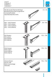
Contents E<br />
Systems overview, manuals for planning and installation<br />
Technical information<br />
E2 - E7<br />
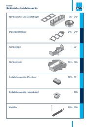
Equipment of data-device carriers<br />
E8 - E9<br />
Screed flush ducts<br />
E10 - E14<br />
Heavy-duty floor duct<br />
E15 - E17<br />
Hollow-space floor box<br />
E18 - E21<br />
Cable duct<br />
E22 - E24<br />
Installation units made of plastic<br />
E25 - E30<br />
Installation units made of high-grade steel, heavy-duty<br />
E31<br />
Installation units made of high-grade steel, cartridge units<br />
E32 - E34<br />
Single outlets, round<br />
E35 - E36<br />
Single outlets, quadrangular<br />
E37 - E39<br />
Device mounting cups<br />
E40 - E41<br />
Device installation cup and cover plates / Device carriers<br />
E42 - E43<br />
Data-device carriers<br />
E44<br />
Device carrier CEE socket<br />
E45
Systems overview, manuals for planning and installation<br />
Premises for assembly<br />
Premises for assembly – on site<br />
The following premises need to be fulfilled before assembly of a<br />
underfloor duct system can begin:<br />
<br />
of all installation units.<br />
<br />
<br />
<br />
<br />
tolerances of DIN 18 202<br />
<br />
<br />
and subsonic noise behaviour<br />
<br />
extraneous material<br />
<br />
provided<br />
The underfloor system must be designed according to<br />
DIN EN 50085 and DIN VDE 0604.<br />
Floor screed works<br />
Duct systems and accessories are components that reach<br />
their full capacity of working load for their intended use only in<br />
connection with floor screed.<br />
In detail the following requirements are indispensable:<br />
<br />
inserted,<br />
<br />
<br />
<br />
strained by other weight,<br />
<br />
must be provided,<br />
<br />
<br />
completely hardened,<br />
<br />
35 mm thick at least for office and work areas with<br />
distributed loads of up to 1.5 kN/m² the minimum screed cover<br />
over the duct system is 35 mm. In case of higher loads the<br />
nominal thickness of the screed needs to be accordingly higher.<br />
The areas around the floor boxes and the screed flush ducts<br />
need a good densification and concision in order to avoid later<br />
unevenness and cracking of the bottom covering.<br />
The floor boxes can be used from the following minimum screed<br />
thickness:<br />
Marking Duct Minimum Application<br />
height height<br />
UBDHB350/250 28 28 mm 65 mm Feeding box<br />
UBDHB350/250 38 38 mm 75 mm Feeding-/Installation box<br />
UBDHB350/250 48 48 mm 85 mm Feeding-/Installation box<br />
In case of using the hollow space floor box with shuttering unit it<br />
is necessary to:<br />
<br />
damage,<br />
<br />
<br />
<br />
decoupling the floor box from screed,<br />
<br />
Hot asphalt<br />
<br />
temperatures with adequate insulating layers.<br />
<br />
be removed after the asphalt has cooled down. The resulting<br />
opening between shuttering unit and asphalt needs to be filled<br />
with appropriate material flush with the surface area.<br />
<br />
hardening.<br />
Including the duct system into the safety measures<br />
<br />
the safety measures.<br />
<br />
<br />
welding the parts, riveting or construction of a firm compression<br />
<br />
<br />
conductor for potential equalisation.<br />
<br />
equalisation during electric installation works.<br />
<br />
used it is sufficient to include only the floor boxes into the<br />
safety measures. Each floor box body comes with a grounded<br />
conductor clamp.<br />
<br />
components must be carried out flexible.<br />
The defined linear electric impedance of duct systems for electric<br />
installation is 0.001 ohm per meter.<br />
E2
Systems overview, manuals for planning and installation<br />
Impact noise characteristics<br />
Sound insulation in case of usage of screed covered<br />
underfloor installation ducts<br />
Sound insulation requirements for buildings are regulated by DIN<br />
4109. The aim is to keep the noise emission as low as possible.<br />
Acoustic decoupling between raw floor, duct system and screed<br />
by means of insulation layers is the basic requirement, resulting<br />
in the construction of a floating floor screed.<br />
If that is not the case excitation of structure-borne noise is directly<br />
transferred to the raw floor and the subsonic noise can only be<br />
minimized with a soft resilient floor covering.<br />
Measurement method<br />
L = level | = difference | n,w = evaluated on site<br />
Result of examination<br />
The measuring results show that the <strong>PUK</strong> Underfloor System<br />
meets the requirements of subsonic noise protection for ceilings<br />
in office buildings of 53 dB in all tests with all proper applications.<br />
Measuring the subsonic noise behaviour of screed covered duct<br />
systems took place between testing rooms on site according to<br />
DIN EN ISO 140-7.<br />
A standardised forge initiates structure-borne noise in the<br />
broadcasting room. The received levels are measured with the<br />
measurement equipments real-time-analyser and microphone.<br />
Taking volume and reverberation period into consideration this<br />
results in the normalised impact sound pressure level L`n,w<br />
as a<br />
parameter for the structural element.<br />
The reduction of subsonic noise L w<br />
<br />
between the stated subsonic noise on the raw floor L`n,w,eq,R<br />
and<br />
the respective measuring result L`n,w<br />
.<br />
<br />
enough to make sure that the required standard subsonic noise<br />
level in office buildings is not transgressed.<br />
ting<br />
screed is completely unproblematic with reference to subsonic<br />
noise behaviour.<br />
<br />
directly to the installation unit or the screed if carpet- or parquetfloor<br />
cover is in use.<br />
An additional decoupling of the levelling system from<br />
<br />
results in the increase of subsonic noise protection of 6 dB compared<br />
to the assembly of the levelling system directly to the raw<br />
floor.<br />
The new hollow space floor box has the advantage of complete<br />
mechanical decoupling from the duct system which is especially<br />
<br />
floor constructions.<br />
The required standard subsonic noise level in office buildings has<br />
been specified as follows:<br />
<br />
L`n,w<br />
≤ 53 db (DIN 4109 table 3)<br />
<br />
L`n,w<br />
≤ 46 db (DIN 4109 supplement 2 table 3)<br />
E3
Systems overview, manuals for planning and installation<br />
Impact noise characteristics<br />
Inspection with duct 3-38-350S, hollow space floor box UBDHB350 38-308R and installation unit UEKDD3-R-G, round<br />
Test setup<br />
Floor assembly without duct system and floor cover<br />
L`n,w<br />
41 dB<br />
3<br />
5<br />
1<br />
6<br />
2<br />
4<br />
Duct system installed into floating screed, structure-borne<br />
noise is initiated without floor covering material<br />
Duct system installed into floating screed, structure-borne<br />
noise is initiated on textile floor covering material<br />
45 dB<br />
36 dB<br />
Assembly:<br />
1. 6 mm carpet 4. 10 mm noise-insulating board<br />
2. 45 mm cement screed 5. 40 mm noise-insulating board<br />
3. 2 mm foil 6. 160 mm raw floor<br />
L`n,w,eq,R<br />
= 75 dB<br />
Measured data from test report 3-091 dated 2003.07.23.<br />
Inspection with duct UK 2-38-250S, hollow space floor box UBDHB250 38-259V and installation unit UEKDD-V-G, angular<br />
Test setup<br />
L`n,w<br />
5<br />
2<br />
3<br />
1<br />
6<br />
4<br />
Floor assembly without duct system and floor cover<br />
Duct system installed into floating screed, structure-borne<br />
noise is initiated on textile floor covering material<br />
Duct system installed into floating screed, structure-borne<br />
noise is initiated on installation unit with textile floor<br />
covering material<br />
38 dB<br />
29 dB<br />
30 dB<br />
Assembly:<br />
1. 6 mm carpet 4. 20 mm noise-insulating board<br />
2. 85 mm cement screed 5. 30 mm thermal insulation board<br />
3. 2 mm foil 6. 300 mm raw floor<br />
L`n,w,eq,R<br />
= 69 dB<br />
Measured data from test report 08-079 dated 19.08.2008<br />
Inspection with duct UK 2-38-250S, hollow space floor box UBDHB250 38-259V and high-grade steel installation unit UEKD<br />
25-V E, angular, mounted on levelling unit UNEG 260V-60S<br />
Test setup<br />
Floor without duct system and without floor cover<br />
L`n,w<br />
38 dB<br />
2<br />
3<br />
1<br />
6<br />
4<br />
5<br />
Duct system installed into floating screed, structure-borne<br />
35 dB<br />
noise is initiated on parquet floor covering material<br />
Duct system installed into floating screed, structure-borne<br />
noise is initiated on installation unit with parquet floor 42 dB<br />
covering material<br />
Assembly:<br />
1. 22 mm parquet 4. 20 mm noise-insulating board<br />
2. 85 mm cement screed 5. 30 mm thermal insulation board<br />
3. 2 mm foil 6. 300 mm raw floor<br />
= 69 dB<br />
L`n,w,eq,R<br />
Measured data from test report 08-079 dated 19.08.2008<br />
E4
Systems overview, manuals for planning and installation<br />
Cable design inside the duct<br />
H B B1 B2 B3<br />
mm mm mm mm mm<br />
high voltage IT-line<br />
Ø 10 CAT-6 Ø 8<br />
pieces pieces<br />
UK<br />
screed covered duct, 2 compartments<br />
H<br />
20<br />
B<br />
B1<br />
Pmax<br />
B2<br />
20<br />
L<br />
S<br />
UK 2-28-190S 28 190 95 95 - 32 50<br />
UK 2-28-250S 28 250 125 125 - 42 66<br />
UK 2-28-350S 28 350 175 175 - 59 92<br />
UK 2-38-190S 38 190 95 95 - 43 68<br />
UK 2-38-250S 38 250 125 125 - 57 89<br />
UK 2-38-350S 38 350 175 175 - 80 125<br />
UK 2-48-190S 48 190 95 95 - 55 86<br />
UK 2-48-250S 48 250 125 125 - 72 113<br />
UK 2-48-350S 48 350 175 175 - 101 158<br />
UKL<br />
screed covered duct, 3 compartments<br />
S<br />
UKL 3-28-250S 28 250 82 84 82 42 66<br />
UKL 3-28-350S 28 350 116 116 116 59 92<br />
H<br />
Pmax<br />
UKL 3-38-250S 38 250 82 84 82 57 89<br />
UKL 3-38-350S 38 350 116 116 116 80 125<br />
UKL 3-48-250S 48 250 82 84 82 72 113<br />
UKL 3-48-350S 48 350 116 116 116 101 158<br />
20<br />
B1<br />
B<br />
B2<br />
B1<br />
20<br />
L<br />
Planning must be based on the cable volume.<br />
The diameters of the selected customary cable types<br />
are average values.<br />
Duct filling factor max 60% with a distance of 8 m<br />
between floor boxes recommended.<br />
Current load see DIN VDE 0100/0298<br />
UK<br />
UKL<br />
H<br />
H<br />
B1<br />
B2<br />
B1<br />
B2<br />
B3<br />
20 B<br />
20<br />
20 B<br />
20<br />
E5
Systems overview, manuals for planning and installation<br />
Cable design inside the duct<br />
H B B1 B2 B3<br />
mm mm mm mm mm<br />
high voltage IT-line<br />
Ø 10 CAT-6 Ø 8<br />
pieces pieces<br />
UKR 2<br />
cable duct bottom piece 2 compartments<br />
S<br />
UKR 35-30S 35 300 150 150 - 63 98<br />
H<br />
B<br />
B1<br />
B2<br />
L<br />
UKR 3<br />
cable duct bottom piece 3 compartments<br />
H<br />
B1<br />
B<br />
B2<br />
B3<br />
L<br />
S<br />
UKR 35-40S 35 400 133 133 133 84 131<br />
UKR 35-50S 35 500 166 166 166 105 164<br />
UKR 60-40S 60 400 133 133 133 144 225<br />
UKR 60-50S 60 500 166 166 166 180 281<br />
UKR 85-40S 85 400 133 133 133 204 319<br />
UKR 85-50S 85 500 166 166 166 225 398<br />
UKR 110-40S 110 400 133 133 133 204 413<br />
UKR 110-50S 110 500 166 166 166 330 516<br />
Planning must be based on the cable volume.<br />
The diameters of the selected customary cable types<br />
are average values.<br />
Duct filling factor max 60% with a distance of 8 m<br />
between floor boxes recommended.<br />
Current load see DIN VDE 0100/0298<br />
UKR 2 UKR 3<br />
H<br />
H<br />
B1<br />
B2<br />
B1<br />
B2<br />
B3<br />
B<br />
B<br />
E6
Systems overview, manuals for planning and installation<br />
Casing depth device cup including installation MA-Article device<br />
Casing depth device cup including installation device in plastic installation units<br />
A head space > 65 mm between raw ceiling and floor cover<br />
surface is needed for coupler plugs in device insert.<br />
A head space > 87 mm between raw ceiling and floor cover<br />
surface is needed for angle plug in electrical socket inside<br />
device cup.<br />
A head space > 102 mm between raw ceiling and floor cover<br />
surface is needed for flexible straight line plug in electrical<br />
socket inside device cup.<br />
A head space > 131 mm between raw ceiling and floor<br />
cover surface is needed for inflexible straight line plug<br />
resp. charging set in electrical socket inside device cup<br />
in connection with registering extension for device cup<br />
installation.<br />
Please observe the above specified dimensions for floor construction!<br />
Installation into high-grade steel installation units may require increased casing depths.<br />
E7
Systems overview, manuals for planning and installation<br />
Equipment of data-device carriers<br />
Mounting boards UDEP and device carrier UGET 113 to contain data and media technology for<br />
Device carrier UGETD<br />
Device mounting cup UG<br />
UDEP Manufacturer Mounting UGET 113<br />
light wave technology<br />
UDEP-SCD 4<br />
SC-Duplex<br />
UGET-3-SCD 113<br />
UDEP-SCS 4<br />
SC-Simplex<br />
LC-Duplex<br />
UGET-3-SCS 113<br />
LC Duplex multimedia<br />
UGET-2-LCDM 113<br />
data technology<br />
UDEP-BTR 3<br />
BTR<br />
BTR<br />
BTR<br />
BTR<br />
BTR<br />
Dätwyler<br />
Leoni Kerpen<br />
Rutenbeck<br />
E-DAT module Cat.6 8(8)<br />
E-DAT module connector 8(8) Cat.6 8(8) 90° Cat.6<br />
UAE module Cat.5e 8(8) or Cat.6 8(8)<br />
OpDAT module LC or ST<br />
KOAX module F/F or F/IEC-plug or socket<br />
unilan® RJ45-Modul MS 1/8 Cat.6/EA screened<br />
VarioKeystone® socket module RJ45 or 4K7 or 4K6<br />
UM-real.Cat.6a B screened<br />
UGET-2-BTR 113<br />
UDEP-COR 3<br />
Corning LANscape S250 module RJ45 Kat. 6<br />
UGET-2-COR 113<br />
UDEP-AMP 3<br />
AMP<br />
Corning<br />
Siemon<br />
FutureCom F S1200 module<br />
TERA<br />
UGET-2-AMP 113<br />
UDEP-AMP SL3<br />
AMP<br />
AMP<br />
AMP<br />
TWIST 6AS SL Jack<br />
TWIST 6S SL Jack<br />
TWIST 7AS SL Jack<br />
UGET-2-AMPSL 113<br />
UDEP-GG45 3<br />
3M Deutschland GmbH<br />
3M Deutschland GmbH<br />
3M Deutschland GmbH<br />
Brand-Rex<br />
Brand-Rex<br />
CobiNet<br />
Dätwyler<br />
Nexans<br />
<br />
<br />
<br />
Cat6Plus screened module C6CJAKS000<br />
10GPlus screened module AC6JAKS000<br />
RJ45-module TopKey Cat. 6 class E<br />
Unilan PS-GG45 7A 1000 MHz with clip<br />
LANmark module with Keystone clip red<br />
UGET-2-GG45 113<br />
UDEP-KR 2<br />
ADC KRONE<br />
ADC KRONE<br />
Brand-Rex<br />
Brand-Rex<br />
Dätwyler<br />
Dätwyler<br />
Leoni Kerpen<br />
Rutenbeck<br />
Rutenbeck<br />
Telegärtner<br />
Telegärtner<br />
TrueNet® KM8® RJ45 socket Kat. 6<br />
TrueNet® CL RJ45 socket Kat. 6<br />
Cat6Plus screened module C6CJAKS000CR "old version"<br />
10G screened module AC6JAKS000CR "old version"<br />
Unilan MS-K 1/8 socket module<br />
Unilan KS-T 1/8 socket module<br />
Eline Keystone-socket RJ45 Kat. 6 tool-less<br />
UM-real.Cat.6 U A not screened<br />
UM-real.Cat.6a A screened<br />
AMJ-Modul K Cat.6A (J00029K0036 / J00029A0077)<br />
AMJ-S-Modul Cat.6A (J00029A2000 / J00029A2001)<br />
UGET-2-KR 113<br />
E8
Systems overview, manuals for planning and installation<br />
Equipment of data-device carriers<br />
data technology<br />
UDEP-RM 2<br />
R&M<br />
R&M<br />
R&M<br />
module fixture for E-2000-Compact,<br />
module fixture for universal adapter with carrier plate<br />
module fixture for SC-RJ coupler with carrier plate<br />
UGET-1-RM 113<br />
UDEP-RMSC 2<br />
R&M<br />
R&M<br />
Anschlussmodul, Kat. 5e, 1xRJ45/s, Snap-In<br />
Anschlussmodul, Kat. 6, Real 10, 1xRJ45/s, Snap-In<br />
UDEP-RMSC 3<br />
Brand-Rex<br />
Brand-Rex<br />
Dätwyler<br />
Dätwyler<br />
ECOLAN<br />
EFB<br />
eku Kabel & Systeme<br />
Leoni Kerpen<br />
R&M<br />
R&M<br />
Rutenbeck<br />
Rutenbeck<br />
Telegärtner<br />
Telegärtner<br />
Cat6Plus screened module C6CJAKS000CR "old version"<br />
10G screened module AC6JAKS000CR "old version"<br />
Unilan MS-K 1/8 socket module<br />
Unilan KS-T 1/8 socket module<br />
ELN336102 Cat.6a<br />
E-20070 Cat.6a<br />
E-Stone module Cat.6A, t66851000<br />
Eline socket RJ45 Kat. 6 tool-less<br />
Kat. 5e, 1xRJ45/s, Snap-In<br />
Kat. 6, Real 10, 1xRJ45/s, Snap-In<br />
UM-real.Cat.6 U A not screened<br />
UM-real.Cat.6a A screened<br />
AMJ-module K Cat.6A (J00029K0036 / J00029A0077)<br />
AMJ-S-module Cat.6A (J00029A2000 / J00029A2001)<br />
UGET-2-RMSC 113<br />
UDEP-KEL 3<br />
LEONI Kerpen<br />
LEONI Kerpen<br />
LEONI Kerpen<br />
LEONI Kerpen<br />
LEONI Kerpen<br />
ELine 1200® EC7<br />
ELine 500 plus socket<br />
ELine 500 RJ45 S socket<br />
ELine 250® RJ45 S socket<br />
ELine 250® RJ45 U socket<br />
UDEP-SYS 2<br />
Systimax<br />
Systimax<br />
MPS 100E cat5, MPS S200E<br />
MGS 300, MGS 400, MGS 500X10D, MGS 600X10D<br />
(required: Systimax Einbaurahmen type: M30MC)<br />
plug-in systems<br />
UDEP-5PK 1<br />
WAGO<br />
WINSTA ® MIDI Snap-In sockets or plugs 5-pole<br />
UGET-1-5PK 113<br />
UDEP-5PCOM 1<br />
WAGO<br />
Snap-In spcket X-COM, 5-pole, 500 V, 32 A<br />
UGET-1-5PCOM 113<br />
UDEP-3PK 2<br />
Wieland<br />
Snap-In sockets or<br />
plugs 2-pole (EIB-Bus) and 3-polig (Net)<br />
UGET-2-3PK 113<br />
audio- / video technology<br />
UDEP-KM 1<br />
Kindermann<br />
UDEP-KM 1:<br />
<br />
UGET-2-KM 113:<br />
<br />
UGET-2-KM 113<br />
UDEP-XLR 2<br />
Neutrik<br />
D Serie, DL Serie, DLX Serie<br />
UGET-2-XLR 113<br />
installation units, pre-snap-in<br />
PEHA<br />
Legrand<br />
Simon<br />
2 x 22,5 x 45 mm or<br />
1 x 45 x 45 mm<br />
UGET-1-UST45 113<br />
E9
Systems overview, manuals for planning and installation<br />
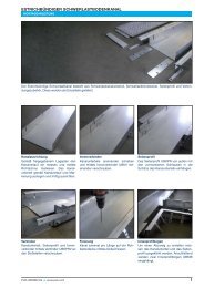
Screed flush duct<br />
Assembly instructions – screed flush duct systems<br />
Screed flush duct<br />
<br />
and accessories<br />
<br />
alloy profile and bolt together<br />
<br />
<br />
<br />
<br />
<br />
E10
Systems overview, manuals for planning and installation<br />
Screed flush duct<br />
Assembly instructions – screed flush duct systems<br />
Screed flush duct<br />
<br />
<br />
<br />
the branch<br />
<br />
<br />
<br />
<br />
<br />
<br />
<br />
E11
Systems overview, manuals for planning and installation<br />
Screed flush duct Mounting kit T-branch<br />
Assembly instructions – screed flush duct systems<br />
Screed flush duct – Mounting kit T-branch<br />
For duct branches a cut-out needs to be made in the side profile (1) and<br />
in the plastic angle profile (2) as wide as the branching UEBK-duct. Please<br />
note that the carpet profile (3) needs to be 12 mm longer on each side.<br />
Both plastic couplers UEBKV (4) are inserted into the side profile and the<br />
corner connections UEBKVE S (5) are pushed into the provided profile,<br />
then fastened with the included screws. Two additional levelling supports<br />
UEBKST (6) are mounted.<br />
The UEBK-duct branch can now be pushed and then fastened into the<br />
prepared opening. Now you can apply the duct cover UEBKD (9) and<br />
screw it together with the transverse cross bar UEBKT (8) and the side<br />
profiles.<br />
A (mm)<br />
UEBK 60-20S 230,5<br />
UEBK 60-30S 330,5<br />
UEBK 60-40S 430,5<br />
A threaded rod GB M10 (10) needs to be screwed in dead centre into the<br />
thread in order to support the transverse cross bar (8). Cut the protruding<br />
threaded rod flush.<br />
Mounting material for a T-branch: 1 x UEBKMA<br />
E12
Systems overview, manuals for planning and installation<br />
Screed flush duct Mounting kit 90° bend<br />
Assembly instructions – screed flush duct systems<br />
Screed flush duct – Mounting kit 90° bend<br />
For corner branches in ducts a cut-out needs to be made in the side<br />
profile (1) and in the plastic angle profile (2) as wide as the branching<br />
UEBK-duct. Please note that the carpet profile (3) needs to be 12 mm<br />
longer on each side.<br />
Now a transverse cross bar UEBKT (4) is mounted and an additional<br />
levelling support UEBKST (5+6) is placed at the ends of the side profiles.<br />
The end piece UEBKEB (7) in the respective width closes the front end.<br />
Push the included plastic connecting block UEBKV (8) into the free side<br />
profile.<br />
The couplers UEBKVE S (10) and UEBKV S (11) are pushed into the<br />
provided profile and fastened with the included screws. The branching<br />
UEBK-duct (9) can now be pushed and then fastened into the prepared<br />
opening.<br />
Now you can apply the duct cover UEBKD (12) and screw it together with<br />
the transverse cross bar UEBKT (8) and the side profiles.<br />
Mounting material for a corner branch: 1x UEBKMB<br />
A (mm)<br />
UEBK 60-20S 219,0<br />
UEBK 60-30S 319,0<br />
UEBK 60-40S 419,0<br />
E13
Systems overview, manuals for planning and installation<br />
Screed flush duct Mounting Information<br />
Assembly instructions – screed flush duct systems<br />
Screed flush duct – Mounting Installation<br />
<br />
course<br />
<br />
<br />
<br />
hinged covers<br />
<br />
<br />
<br />
<br />
covering edge<br />
E14
Systems overview, manuals for planning and installation<br />
Heavy-duty floor duct<br />
Assembly instructions – screed flush duct systems<br />
Heavy-duty floor duct<br />
<br />
delivered as individual parts<br />
<br />
<br />
<br />
UBKV<br />
<br />
of the bottom piece from the outside<br />
<br />
<br />
<br />
E15
Systems overview, manuals for planning and installation<br />
Heavy-duty floor duct<br />
Assembly instructions – screed flush duct systems<br />
Heavy-duty floor duct<br />
<br />
<br />
<br />
0,3 m and insert behind the inward profile bend<br />
<br />
<br />
<br />
<br />
<br />
<br />
E16
Systems overview, manuals for planning and installation<br />
Heavy-duty floor duct Mounting Information<br />
Assembly instructions – screed flush duct systems<br />
Heavy-duty floor duct – Mounting Installation<br />
<br />
<br />
<br />
<br />
<br />
<br />
bottom piece<br />
E17
System overview, Manuals for planning and installation<br />
Hollow space floor box, round<br />
Assembly instructions – floor trunking systems<br />
Hollow space floor box, round<br />
Hollow space floor box for round installation units Ø 305 mm or Ø 258 mm and underfloor ducts up to 250 or 350 mm width, heights 28/38/48 mm.<br />
Observe minimum screed covering of 35 mm.<br />
Hollow space floor box<br />
Align floor box dead centre to the duct course.<br />
Fasten to the slab with two nail plugs and screw<br />
tight the grounding lug.<br />
Duct / hollow space floor box<br />
Bend open side walls at the perforation. Push<br />
duct to dead stop into the box. Set one floor box<br />
per change of direction in the duct system.<br />
Duct<br />
Cut duct, lay up and align. Burr and galvanize<br />
cutting edges. Fastening with two nail plugs<br />
<br />
Jointing bracket<br />
Align duct segments flush and push together.<br />
<br />
Fasten with two nail plugs. Factor in potential<br />
equalization when inserting plugs.<br />
Inserting shuttering units<br />
Insert shuttering units straight from the top into<br />
the floor box opening.<br />
Floor box and shuttering unit make one<br />
mounting unit. Latch a second shuttering<br />
unit on top for floor constructions higher than<br />
150 mm.<br />
Insulation<br />
Masking of all openings in the duct system.<br />
Apply insulation flush to duct system and<br />
shuttering unit.<br />
E18
Systems overview, manuals for planning and installation<br />
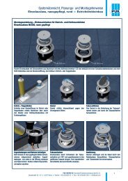
High-grade steel Installation unit, cartridge unit round<br />
Assembly instructions – floor trunking systems<br />
High-grade steel Installation unit, cartridge unit round<br />
Screed works<br />
No levelling needed before screed is applied.<br />
The shuttering unit needs to be sprayed with<br />
formwork oil. Foil thickness must be < 2 mm.<br />
Subsonic noise insulation<br />
The underfloor system needs to be insulated<br />
against subsonic noise. Mask the shuttering<br />
unit revolving with foil. Apply screed neatly to<br />
the shuttering unit.<br />
Removal of shuttering unit<br />
Remove shuttering unit with the release cord<br />
from the hardened screed. Process bottom<br />
covering to the cleaned assembly opening<br />
(Ø 260 mm, Ø 308 mm).<br />
Plastic installation unit<br />
Use for dry maintenance floor.<br />
Loosen cover from the installation frame and<br />
apply carpet. Observe insertion depth. Insert<br />
claws into the frame. Bolt installation unit tightly<br />
into the floor opening.<br />
Levelling device<br />
For parquet or stone floors insert the levelling<br />
device into the floor opening. Fasten the four<br />
levelling bases to the floor with nail plugs.<br />
Lock-in leads<br />
Fasten both lock-in leads to the frame from<br />
the bottom, using 2 screws for each. Make the<br />
grounding connection between levelling device<br />
and floor box.<br />
Alignment to floor<br />
<br />
bolts flush with the final floor height. Seal the<br />
<br />
agent. When using a device plug H = 35 mm,<br />
minimum installation depth Hmin = 100 mm.<br />
Dummy / cable outlet cartridge<br />
Use for wet maintenance floors. Apply parquet<br />
to the cartridge. Observe insertion depth. Insert<br />
cartridge into the frame. Cartridges can be<br />
exchanged.<br />
Tube outlet cartridge<br />
Use for wet maintenance floors.<br />
Apply stone covering material to the cartridge.<br />
Observe insertion depth. Insert cartridge into<br />
the frame. Tube can be bolted together.<br />
E19
System overview, Manuals for planning and installation<br />
Hollow space floor box, quadrangular<br />
Assembly instructions – floor trunking systems<br />
Hollow space floor box, quadrangular<br />
Hollow space floor box for angular installation units 258 x 258 mm or 258 x 184 mm and underfloor ducts up to 250 or 350 mm width, heights<br />
28/38/48 mm. Observe minimum screed covering of 35 mm.<br />
Hollow space floor box<br />
Align floor box dead centre to the duct course.<br />
Fasten to the slab with two nail plugs and screw<br />
tight the grounding lug.<br />
Duct / hollow space floor box<br />
Bend open side walls at the perforation. Push<br />
duct to dead stop into the box. Set one floor box<br />
per change of direction in the duct system.<br />
Duct<br />
Cut duct, lay up and align. Burr and galvanize<br />
cutting edges. Fastening with two nail plugs<br />
<br />
Jointing bracket<br />
Align duct segments flush and<br />
<br />
<br />
potential equalization when inserting plugs.<br />
Inserting shuttering units<br />
Insert shuttering units straight from the top into<br />
the floor box opening.<br />
Floor box and shuttering unit make one<br />
mounting unit. Latch a second shuttering<br />
unit on top for floor constructions higher than<br />
150 mm.<br />
Insulation<br />
Masking of all openings in the duct system.<br />
Apply insulation flush to duct system and<br />
shuttering unit. Prior to screed application no<br />
levelling necessary.<br />
E20
Systems overview, manuals for planning and installation<br />
High-grade steel Installation unit, cartridge unit quadrangular<br />
Assembly instructions – floor trunking systems<br />
High-grade steel Installation unit, cartridge unit quadrangular<br />
Screed work / impact-noise decoupling<br />
Spray shuttering unit with formwork oil. Film<br />
thickness must be < 2 mm. With underfloor<br />
systems impact-noise must be decoupled.<br />
Shuttering unit must be masked with a film all<br />
around. Apply screed neatly to the shuttering<br />
unit.<br />
Removal of shuttering unit<br />
Remove shuttering unit with the release cord<br />
from the hardened screed. Process bottom<br />
covering to the cleaned assembly opening<br />
(261 x 261 mm, 261 x 186 mm).<br />
Plastic installation unit<br />
Use for dry maintenance floor.<br />
Loosen cover from the installation frame and<br />
apply carpet. Observe insertion depth. Insert<br />
claws into the frame. Bolt installation unit tightly<br />
into the floor opening.<br />
Levelling device<br />
For parquet or stone floors insert the levelling<br />
device into the floor opening. Fasten the four<br />
levelling bases to the floor with nail plugs.<br />
High-grade steel frame<br />
Screw the high-grade steel frame to the<br />
levelling device with four screws. Glue rubber<br />
seal in place. Make the grounding connection<br />
between levelling device and floor box.<br />
Alignment to floor<br />
<br />
levelling bolts flush with the final floor height.<br />
<br />
sealing agent.<br />
Lock-in leads<br />
Fasten both lock-in leads to the frame from the<br />
bottom with 2 screws each. Make an earthing<br />
connection between the levelling device and<br />
floor box. When using a device plug H = 35 mm,<br />
minimum installation depth Hmin = 94 mm.<br />
Dummy / cable outlet cartridge<br />
Use for wet maintenance floors. Apply parquet<br />
to the cartridge. Observe insertion depth. Insert<br />
cartridge into the frame. Cartridges can be<br />
exchanged.<br />
Tube outlet cartridge<br />
Use for wet maintenance floors.<br />
Apply stone bottom covering material to the<br />
cartridge. Observe insertion depth. Insert<br />
cartridge into the frame. Tube can be bolted<br />
together.<br />
E21
Systems overview, manuals for planning and installation<br />
Cable duct<br />
Assembly instructions – floor trunking systems<br />
Cable duct<br />
<br />
<br />
<br />
<br />
<br />
<br />
symmetrically with dowels<br />
<br />
E22
Systems overview, manuals for planning and installation<br />
Cable duct<br />
Assembly instructions – floor trunking systems<br />
Cable duct<br />
<br />
<br />
<br />
<br />
<br />
<br />
<br />
<br />
the opening<br />
E23
Systems overview, manuals for planning and installation<br />
MA-Article<br />
Cable duct Mounting Information<br />
Assembly instructions – floor trunking systems<br />
Cable duct – Mounting Information<br />
<br />
<br />
<br />
<br />
<br />
<br />
E24
Systems overview, manuals for planning and installation<br />
Installation unit made of plastic, Installation unit round<br />
Assembly instructions – Installation units for screed and hollow floors<br />
Installation unit made of plastic, Installation unit round<br />
Round installation units, external diameter Ø 305 or Ø 258 mm, for installation of up to three device containers.<br />
Screed floors<br />
For screed covered systems remove shuttering<br />
unit and mount directly into the opening.<br />
Hollow space and raised floors<br />
At hollow space and raised floors insert directly<br />
into the installation opening.<br />
Remove hinged cover<br />
<br />
out with tongs until the snap tabs are released<br />
from the frame. Remove cover to the front.<br />
Mounting claws<br />
Mount the enclosed standard claw fasteners<br />
(range of claws 30 to 50 mm) into the<br />
acceptance in the frame.<br />
Fastening installation frame<br />
Insert installation unit into the opening and level<br />
unit. Fasten Phillips screws and check frame for<br />
straight seating.<br />
Inserting device containers<br />
Click device containers as deep as possible into<br />
the lock-in leads.<br />
E25
Systems overview, manuals for planning and installation<br />
Installation unit made of plastic, Installation unit round<br />
Assembly instructions – Installation units for screed and hollow floors<br />
Installation unit made of plastic, Installation unit round<br />
Lock-in leads<br />
For lowering the device container gradually<br />
down to 30 mm.<br />
Minimum installation height<br />
Minimum installation height 74 mm and 87 mm<br />
for device plugs up to h = 35 mm.<br />
Maximum installation height<br />
Maximum installation height 104 mm for device<br />
plugs up to h = 50 mm.<br />
Loosen device container<br />
Insert screwdriver or mounting lever between<br />
frame and device container. Loosen snap tab<br />
and remove device container.<br />
Insert hinged cover<br />
<br />
snap tabs lock into the opening in the frame.<br />
Insert cover to the back into the frame.<br />
Glue in bottom covering<br />
Cut bottom coverings up to 8 mm accurately<br />
fitting and glue to the steel insert. Optional lid<br />
insert H = 3 mm.<br />
Opening lever<br />
Self-locking opening lever behind the cable<br />
outlet.<br />
Cable outlet<br />
Swing around carriage cover by 180° and snap<br />
in.<br />
Leading cables through<br />
Leading cables through the open cable outlet.<br />
E26
Systems overview, manuals for planning and installation<br />
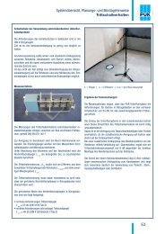
Shuttering unit, round<br />
Assembly instructions – accessories plastic units<br />
Shuttering unit, round<br />
Round shuttering units in 2 designs, deep-drawing piece made of 1 mm plastic, hight 50 mm for providing an opening in the hollow floor.<br />
Levelling of shuttering unit<br />
Provide openings with cross section 307 mm or<br />
260 mm in the assembled basic floor.<br />
Fixation of shuttering unit<br />
Level the shuttering units on the hollow floor<br />
before application of screed.<br />
Mounting of foil<br />
Fix shuttering units to the floor with adhesive<br />
tape, cut out foil and overlap.<br />
Inserting screed<br />
Spread the screed on the whole area and<br />
compact it neatly.<br />
Cut out opening<br />
After the screed has hardened remove the overlapping<br />
lid and sidewalls neatly.<br />
Mounting assembly unit<br />
After the floor covering has been laid insert the<br />
installation unit straight into the opening and<br />
fasten it with the claws evenly to the screed.<br />
E27
Systems overview, manuals for planning and installation<br />
Installation unit made of plastic, Installation unit quadrangular<br />
Assembly instructions – Installation units for screed and hollow floors<br />
Installation unit made of plastic, Installation unit quadrangular<br />
Angular installation units, external dimension 258 x 258 mm or 258 x 184 mm, for installation of up to three device containers.<br />
Screed floors<br />
For screed covered systems remove shuttering<br />
unit and mount directly into the opening.<br />
Hollow space- and raised floors<br />
For hollow space and raised floors mount<br />
directly into the installation opening.<br />
Remove hinged cover<br />
Open cover completely, pull firmly forward at<br />
<br />
a screwdriver.<br />
Mounting claws<br />
Mount the enclosed standard claw fasteners<br />
(range of claws 30 to 50 mm) into the<br />
acceptance in the frame.<br />
Fastening installation frame<br />
Insert installation unit into the opening and level<br />
unit. Fasten Phillips screws and check frame for<br />
straight seating.<br />
Inserting device containers<br />
Click device containers as deep as possible into<br />
the lock-in leads.<br />
E28
Systems overview, manuals for planning and installation<br />
Installation unit made of plastic, Installation unit quadrangular<br />
MA-Article<br />
Assembly instructions – Installation units for screed and hollow floors<br />
Installation unit made of plastic, Installation unit quadrangular<br />
Lock-in leads<br />
For lowering the device container gradually<br />
down to 30 mm.<br />
Minimum installation height<br />
Minimum installation height 74 mm and 87 mm<br />
for device plugs up to h = 35 mm.<br />
Maximum installation height<br />
Maximum installation height 104 mm for device<br />
plugs up to h = 50 mm.<br />
Loosen device container<br />
Insert screwdriver or mounting lever between<br />
frame and device container. Loosen snap tab<br />
and remove device container.<br />
Insert hinged cover<br />
Attach opened hinged cover at the left back<br />
side, push firmly to the back on the right side<br />
<br />
Glue in bottom covering<br />
Cut bottom coverings up to 8 mm accurately<br />
fitting and glue to the steel insert. Optional lid<br />
insert H = 3 mm.<br />
Opening lever<br />
Self-locking opening lever behind the cable<br />
outlet.<br />
Cable outlet<br />
Swing around carriage cover by 180° and snap<br />
in.<br />
Leading cables through<br />
Leading cables through the open cable outlet.<br />
E29
Systems overview, manuals for planning and installation<br />
MA-Article<br />
Shuttering unit, quadrangular<br />
Assembly instructions – accessories plastic units<br />
Shuttering unit, quadrangular<br />
Angular shuttering units in 2 designs, deep-drawing piece made of 1 mm plastic, hight 50 mm for providing an opening in the hollow floor.<br />
Levelling of shuttering unit<br />
Provide openings 261x261 mm or 261x186 mm<br />
in the assembled basic floor.<br />
Fixation of shuttering unit<br />
Level the shuttering units on the hollow floor<br />
before application of screed.<br />
Mounting of foil<br />
Fix shuttering units to the floor with adhesive<br />
tape, cut out foil and overlap.<br />
Inserting screed<br />
Spread the screed on the whole area and<br />
compact it neatly.<br />
Cut out opening<br />
After the screed has hardened remove the<br />
overlapping lid and sidewalls neatly. Side walls<br />
must be maintained.<br />
Mounting assembly unit<br />
After the floor covering has been laid insert the<br />
installation unit straight into the opening and<br />
fasten it with the claws evenly to the screed.<br />
E30
Systems overview, manuals for planning and installation<br />
Installation units made of high-grade steel, heavy-duty<br />
Assembly instructions – Installation units for screed and hollow floors<br />
Installation units made of high-grade steel, heavy-duty<br />
High-grade steel installation cartridge with levelling device, round or angular design, as dummy-, cable-outlet- or tube outlet cartridge with steel insert<br />
for working loads up to 10 or 20 KN.<br />
Levelling device<br />
Remove shuttering unit and insert levelling<br />
device into the floor opening. Fasten the four<br />
levelling bases to the slap with drilling screws.<br />
High-grade steel frame<br />
Attach device container installation frame first<br />
and then high-grade steel frame to the levelling<br />
device and fasten with 4 screws. Glue in rubber<br />
sealing.<br />
Levelling to floor<br />
<br />
the floor construction with the four levelling<br />
bolts. Lock the levelling bases against the frame<br />
with hex-nuts.<br />
Dummy cartridge 10 / 20KN<br />
Insert cartridge with integrated steel inlay into<br />
the frame, seal expansion gap. For coverings<br />
thicker than 16 mm in case of applied load<br />
10 kN and 24 mm in case of applied load 20 kN.<br />
Cable outlet cartridge 10 KN<br />
Insert cartridge with integragted steel inlay into<br />
the frame, seal expansion gap. For coverings<br />
thicker than 16 mm.<br />
Tube outlet cartridge 10 / 20 KN<br />
Insert cartridge with integrated steel inlay and<br />
tube mounting set into the frame. Complete<br />
with tube. Seal expansion gap. For coverings<br />
thicker than 16 mm in case of applied load<br />
10 kN and 24 mm in case of applied load 20 kN.<br />
E31
Systems overview, manuals for planning and installation<br />
Installation units made of high-grade steel<br />
Cartridge Installation units, quadrangular<br />
Assembly instructions – Installation units for screed and hollow floors<br />
Installation units made of high-grade steel – Cartridge Installation units, quadrangular<br />
Quadrangular cartridge installation units with carpet protection frame made of high-grade steel with outer measurements of 284x284 mm or<br />
284x211 mm for the installation in hollow space floors or raised floors. For parquet flooring of 12/22 mm.<br />
Unit<br />
For the installation of up to 3 device cups, place<br />
the cartridge installation unit UEKDD V E into the<br />
opening.<br />
Opening lever<br />
Open the self-locking opening lever behind the<br />
cable outlet. Remove the cover sideways over<br />
the hinge.<br />
Claws<br />
Hinge the enclosed claws with the corresponding<br />
screws into the frame guide and pull tight.<br />
Rubber seal<br />
Glue the rubber seal to the impact-noise<br />
interface.<br />
Device cup<br />
Snap the device cup as deep into the lock-in<br />
leads as possible. When using an device plug<br />
H = 35 mm, minimum installation depth Hmin<br />
= 91 mm.<br />
Earthing connection<br />
Make an earthing connection between the<br />
frame and the cover. Factor the installation unit<br />
into the potential equalization.<br />
E32
Systems overview, manuals for planning and installation<br />
Installation units made of high-grade steel<br />
Cartridge Installation units, quadrangular<br />
Assembly instructions – Installation units for screed and hollow floors<br />
Installation units made of high-grade steel – Cartridge Installation units, quadrangular<br />
Quadrangular cartridge unit with carpet protection frame made of high-grade steel with outside measurements of 187x187 mm for the installation in<br />
hollow floors or raised floors, for a floor cover of 12/22 mm or as an inspection chamber with brush wire outlet.<br />
Unit<br />
For the installation of a device cup, place<br />
cartridge unit UEKDD1-2 V E into the opening.<br />
Opening lever<br />
Activate the self-locking opening lever behind<br />
the cable outlet and lift the lid out of the frame<br />
sideways through the hinge.<br />
Mounting of claws<br />
Hinge the enclosed claws with the corresponding<br />
screws into the holding fixtures in the<br />
frame. Bring the claws in the right position and<br />
pull tight with a crosshead screw. Make sure<br />
the frame sits tightly.<br />
Rubber seal<br />
Glue the rubber seal for impact-noise<br />
decoupling into the frame.<br />
Inserting of device cup<br />
Insert plate with the pre-mounted and loaded<br />
device cup through the plate slide as deep into<br />
the lock-in leads in the frame as possible. A<br />
gradual lowering of the plate to max 20 mm<br />
possible.<br />
Earthing connection<br />
Fixate the plate in the lock-in lead and make an<br />
earthing connection between the single outlet<br />
frame and the cover. Factor the installation unit<br />
into the potential equalization.<br />
E33
Systems overview, manuals for planning and installation<br />
Installation units made of high-grade steel<br />
Cartridge Installation units, quadrangular<br />
Assembly instructions – Installation units for screed and hollow floors<br />
Installation units made of high-grade steel – Cartridge Installation units, quadrangular<br />
Unit<br />
For the cable outlet place the cartridge unit<br />
UKDDB1-2 V E into the installation opening of<br />
the raised floor.<br />
Cover opening<br />
Open high-grade steel cover above the brush<br />
and make an earthing connection between the<br />
single outlet frame and the cover. Factor the<br />
installation unit into the potential equalization.<br />
Mounting of the frame<br />
Fixate the frame above the headless screws on<br />
the side firmly into the opening in the floor.<br />
E34
Systems overview, manuals for planning and installation<br />
Single-outlet, wet-maintained, round Direct mounting MA-Article in screed<br />
Assembly instructions – Installation units for screed and hollow floors<br />
Single outlet BODO, wet maintenance floors<br />
Round single-outlet with protection frame made of aluminium with an outside diameter of 133 mm, equipped with an safety socket and a RJ45 data<br />
box or as revision opening. For installation in screed floor or false floor.<br />
Screed / raised floor<br />
Create a floor opening in the screed or raised<br />
floor using a core cutter or through the use of<br />
hollow space floor box with shuttering unit.<br />
Cover lid<br />
Open lid by means of Allen key counter-clockwise.<br />
Remove tube<br />
Put the lid into the grooving of the tube<br />
receptacle and thus unscrew the tube receptacle.<br />
Attach the frame and insert the strain relief<br />
Protection frame have to seal accordingly<br />
when used in wet-maintained floors. Insert<br />
strain relief from below into the opening and<br />
secure the cable. Tighten the claws by means<br />
of cross-head screws.<br />
Tube insert<br />
Bring single-outlet from closed to open state<br />
by swivelling the tube insert by 180°. Insert the<br />
rubber sleeve for a dust-proof sealing.<br />
Equipment<br />
Insert plug and lead cables through the cable<br />
outlet. Tightly screw together tube insert and<br />
tube lid.<br />
E35
Systems overview, manuals for planning and installation<br />
MA-Article<br />
Single-outlet, dry-maintained, round Direct mounting in screed<br />
Assembly instructions – Installation units for screed and hollow floors<br />
Single outlet BODO, dry maintenance floors<br />
Round single outlet with protection frame made of plastic, external diameter 113 mm, equipped with one isolated ground receptacle or as inspection<br />
chamber. For installation into raised or hollow floors.<br />
Raised / hollow floors<br />
Provide a floor opening in the raised floor with<br />
a drill bit.<br />
Cable outlet lid<br />
Open cable outlet lid with a torx wrench counter<br />
clockwise, pull out to open.<br />
Assembly of receptacle<br />
In order to connect, disassemble the<br />
pre- converted single outlet, insert cable and<br />
connect to receptacle. Then assemble cover<br />
plate, receptacle and device cup.<br />
Fasten strain relief and frame<br />
Insert the strain relieves from below and secure<br />
cable. Tighten claws with Phillips head screws.<br />
Cable outlet<br />
Place plug and insert cable outlet lid counter<br />
clockwise with bayonet locking device.<br />
Equipment<br />
Lead the cable from an angular or straight plug<br />
through the cable outlet.<br />
E36
System overview, manuals for planning and installation<br />
Single-outlet, quadrangular Direct mounting in screed<br />
Assembly instructions – Installation units for screed floors and hollow floors<br />
Single outlet – direct mounting in screed<br />
Quadrangular single outlets with outer measurements of 115x115 mm for the integration of up to 2 installation devices of 45x45 mm for direct screed<br />
mounting.<br />
Fixation<br />
Mount the four levelling legs onto the rough<br />
concrete ceiling with nail plugs<br />
Rubber sealing<br />
Remove the lid and glue the rubber in place.<br />
Cable entry<br />
For the cable entry use a tool to break the lateral<br />
perforation out of the frame and complete with<br />
strain relief.<br />
Safety sockets<br />
Install electrical sockets and fuse strain relief.<br />
Assembly<br />
Latch the sockets into the frame. Factor the single<br />
outlet into the potential equalization.<br />
Floor adjustment<br />
Place the single outlet abreast finished floor<br />
level flush with the four levelling screws. Screed<br />
can now be applied.<br />
E37
System overview, manuals for planning and installation<br />
Single-outlet, quadrangular Hollow space floor box<br />
Assembly instructions – Installation units for screed floors and hollow floors<br />
Single outlet – hollow space floor box<br />
Quadrangular single outlets with outer measurements of 160x160 mm for the integration of up to 2 installation devices of 45x45 mm for fixture in<br />
hollow space floor boxes.<br />
Hollow space floor box<br />
Align floor box in centre to cable run. Mount<br />
onto rough ceiling with two nail plugs.<br />
Duct<br />
Screw on earthing lug. Bend the sides of the<br />
floor box open along the perforation. Insert duct<br />
all the way into the box.<br />
Shuttering unit<br />
Insert the shuttering unit, process screed to<br />
the body, remove the shuttering unit after<br />
precipitation.<br />
Fixation<br />
Insert the frame and mount the four levelling<br />
legs onto the bottom of the hollow floor box<br />
with nail plugs.<br />
Floor adjustment<br />
<br />
four levelling screws. Screw in the lock-in leads.<br />
Cover plate<br />
Fix the cover plate onto the device cup with<br />
screws.<br />
E38
System overview, manuals for planning and installation<br />
Single-outlet, quadrangular Hollow space floor box<br />
Assembly instructions – Installation units for screed floors and hollow floors<br />
Single outlet – hollow space floor box<br />
Fixture of installation tools<br />
Latch installation tools 45x45xmm in the cover<br />
plate UARM-4-1 118 2.<br />
Device cup<br />
Place the device cup into plate, insert the ducts<br />
into strain relief and screw in the fixing bolt.<br />
Lock-in lead<br />
Insert the plate above the plate slide as deeply<br />
into the lock-in leads as possible. For a stepwise<br />
shafting of the plate until up to 20 mm.<br />
Installation of installation devices<br />
In cover plate UARM-3-1 118<br />
Latch 1 installation device 45x45 mm and<br />
1 installation device 22,5x45 mm<br />
Installation of installation devices<br />
In cover plate UARM-2-1 118<br />
Latch 2 installation devices 22,5x45 mm<br />
Rubber seal<br />
Glue the rubber seal into the frame<br />
Earthing connection<br />
Establish an earthing connection between the<br />
single outlet frame and the cover. Factor the<br />
single outlet into the potential equalisation.<br />
Single outlet<br />
Close the cover.<br />
Tube<br />
For wet maintenance floors install tube single<br />
outlet and tube.<br />
E39
System overview, manuals for planning and installation<br />
Device cup UG, pre-converted<br />
Assembly instructions – plug socket systems<br />
Device mounting cup UG, pre-converted<br />
Snap-in device mounting cup for round and angular installation units. For up to four heavy-current-engineering devices or three data-processingtechnology<br />
devices. Angle plug insert for floor constructions higher than 75 mm.<br />
Pre-converted device cup<br />
Delivery of factory-provided device cups,<br />
completed with sockets wired for coupler plugs.<br />
Device installation cup<br />
Insert the socket component of the preconverted<br />
3-pole cable into the snap-in piece<br />
of the device installation cup.<br />
Plug-in connector<br />
Self-locking and coded plug-in connectors<br />
provide for error-free assembly with the device<br />
cup. For unlocking unlatch the grey springcatch<br />
with a screwdriver.<br />
Connecting lines<br />
Choose cables according to colour (black:<br />
power supply system; white: data processing<br />
system) and pull them inside the hollow floor.<br />
Installation unit<br />
Insert the device cup (pre-mounted with<br />
connecting cables) bevelled into lock-in leads<br />
and lock in tightly at the opposing side. Use only<br />
the two bottom lock-in positions.<br />
Underfloor distributor<br />
Insert the plug of the 3-pole cable into one of<br />
the six output-sockets of the distributor and<br />
complete with 5-pole input.<br />
E40
System overview, manuals for planning and installation<br />
Device cup UG45, pre-converted<br />
Assembly instructions – plug socket systems<br />
Device mounting cup UG45, pre-converted<br />
Pre-converted device cup, complete with snap-in plug component and pre-wired sockets. Including all covers and mounting material. For latching into<br />
a round or square installation unit. For up to 4 heavy current engineering installation devices. For the installation of 3-pole connecting lines with plug<br />
connector and socket component.<br />
Pre-converted device cups<br />
Delivery of device cups: fully pre-mounted with<br />
sockets and pre-wired on connector plugs.<br />
Device mounting cup<br />
Place the pre-converted device cup into the<br />
lock-in leads of the installation units as deep<br />
as possible.<br />
Connecting lines<br />
Select cables according to colour (black: normal<br />
net, white: data processing net) and length.<br />
Insert the socket component of the 3-pole<br />
connecting line onto the snap-in piece in the<br />
device cup.<br />
Installation unit<br />
Place the complete installation unit with the<br />
device cups from the top into the existing floor<br />
opening and fixate in the floor with claws.<br />
Plug connector<br />
Self-locking and coded plug connectors<br />
facilitate faultless mounting with the device<br />
cup. To release, unlatch the grey spring catch<br />
with a turn screw.<br />
Underfloor distributor<br />
Insert the plug of the 3-pole connecting line in<br />
one of the six output sockets of the distributor<br />
and complete with 5-pole input.<br />
E41
Systems overview, manuals for planning and installation<br />
Device installation cup and cover plates<br />
Assembly instructions – device installation cups, installation devices<br />
Device installation cup and cover plates<br />
Device assembly container for locking into an assembly unit. For up to four installation devices for heavy current engineering or three installation<br />
devices for data systems technology.<br />
Cover plates<br />
Choose cover plates according to the<br />
tion<br />
if needed.<br />
Safety sockets<br />
Snap safety sockets into the corresponding<br />
cover plate.<br />
Strain relief<br />
Insert the four enclosed strain reliefs into the<br />
side openings of the device container and equip<br />
them with the fixing bolts.<br />
Cables<br />
Insert cables from Ø 6 to Ø 13 mm and fasten<br />
the bolt.<br />
Assembly<br />
Install all components. Snap cover plates into<br />
the device container.<br />
Equipment<br />
Equip empty spaces with dummy covers.<br />
E42
Systems overview, manuals for planning and installation<br />
Device installation cup and device carrier<br />
Assembly instructions – device installation cups, installation devices<br />
Device installation cup and device carrier<br />
Installation<br />
Insert the device container as far as possible<br />
into the lock-in leads.<br />
Can be lowered down to 30 mm.<br />
Minimum / Maximum installation height<br />
Minimum installation height 74 mm without<br />
device plugs and 88 mm for device plugs up to<br />
H = 35 mm.<br />
Maximum installation height 104 mm for device<br />
plugs up to H = 50 mm.<br />
Releasing device cup<br />
Push mounting lever or screwdriver between<br />
frame and device cup. Release latches<br />
separately sideways and take out device cup.<br />
Device separator<br />
<br />
equipment use the device separator. Insert<br />
overvoltage protector into the push-terminals<br />
L, N and PE of the socket and complete with<br />
connecting line.<br />
Coulter clip installation devices<br />
Lock in socket and overvoltage protector with<br />
the cover plate into the device cup. Screw<br />
installation devices with coulter clips into the<br />
device cup.<br />
Finalisation<br />
Snap cover plates and screw cover in place.<br />
Close all openings with blind covers.<br />
Angular insert for half a device cup made of coated metal for components of data, fibre optic cable, audio and video technology, also for plug-in<br />
components and installation devices 45x45 mm.<br />
<br />
E43
Systems overview, manuals for planning and installation<br />
MA-Article<br />
Data-device carriers<br />
Assembly instructions – device installation cups, installation devices<br />
Data-device carriers<br />
Data device carrier made of coated metal for snapping into the installation unit. For installation of up to nine single installation devices of data, audio<br />
and video technology, also for components of plug-in technology.<br />
Strain relief<br />
Screw device carrier with strain relief tight<br />
before installation.<br />
Fitted board<br />
Equip device carrier with up to three fitted<br />
boards according to the product specifications<br />
and screw thight.<br />
Single devices<br />
<br />
fitted board from below. Screw single devices<br />
tight according to the specifications.<br />
Assembly of data-device carriers<br />
<br />
lock-in leads and secure the latch on the<br />
opposite side with a screw into the lock-in.<br />
Tailoring<br />
Complete device cup with the corresponding<br />
cables of manufacturer. Note the daylight.<br />
Device carrier<br />
Insert installation devices with coulter clip into<br />
the device carrier from below and screw tight.<br />
Insert cover from above.<br />
E44
Systems overview, manuals for planning and installation<br />
Device carrier CEE MA-Article socket<br />
Assembly instructions – device cup, installation devices,<br />
Device carrier CEE socket<br />
Carrier made of sheet steel with CEE socket 16A or 32A and box for centre installation into a round or quadrangular installation unit. Necessary installation<br />
height must be observed before assembly.<br />
Levelling unit<br />
Position installation frame on finished floor level<br />
height flush with levelling legs. Screw the locking<br />
ladder set sideways to the frame. Locking<br />
ladder set of 50 or 80mm height available.<br />
CEE-Connection socket<br />
Detach CEE socket from box and device carrier<br />
by unscrewing four screws, insert rubber<br />
seal, insert connecting cable into container and<br />
clamp to CEE box. Reassemble device carrier<br />
completely.<br />
Device carrier<br />
Release socket screws on device carrier and<br />
lock-in lead, insert the assembled device carrier<br />
into the lock-in leads from the bottom, open<br />
hexagon socket bead and insert sideways.<br />
Lock-in lead<br />
Device carrier with CEE socket and box in lockin<br />
lead suitable for floor constructions from<br />
160mm. Always use the lowest locking position.<br />
Clamp device carrier firmly with a socket head<br />
wrench.<br />
Angle Plug<br />
For floor constructions of at least 185mm, insert<br />
angle plug from and cartridge cover with cable<br />
outlet. Observe bending radius to avoid pinched<br />
cables.<br />
Straight connector<br />
When using a straight connector, note that the<br />
cover cannot be closed while in use. Protect installation<br />
unit – accident risk!<br />
E45
Systems overview, manuals for planning and installation<br />
Notes