Download Catalogue - Puk
Download Catalogue - Puk
Download Catalogue - Puk

Create successful ePaper yourself
Turn your PDF publications into a flip-book with our unique Google optimized e-Paper software.
UNDERFLOOR SYSTEMS
A<br />
B<br />
C<br />
D<br />
E<br />
FD<br />
FE<br />
H<br />
h<br />
k<br />
KQ<br />
L<br />
N<br />
P<br />
Pmax<br />
Q<br />
Qmax<br />
QLK<br />
QLK<br />
R<br />
Rb<br />
S | t<br />
StA<br />
T<br />
Tmax<br />
TL<br />
cross section (useable) of cable tray<br />
width<br />
color<br />
diameter<br />
assembly<br />
dowel load<br />
load<br />
height<br />
channel height<br />
clamping range<br />
cable cross section<br />
length<br />
levelling range<br />
bracket load<br />
maximum permissible bracket load<br />
line load<br />
maximum permissible line load<br />
distributed load power cable<br />
distributed load control cable<br />
radius<br />
lock-in range<br />
material thickness<br />
distance between supports<br />
depth<br />
max. installation temperature<br />
separating layer<br />
weight per piece<br />
incl.<br />
ABS<br />
AL<br />
B<br />
CU<br />
delivery includes:<br />
see accessories<br />
see PUK catalog page<br />
KB: „Cable Trays“, KS: „Cable Clamps“, UFS: „Underfloor Systems“<br />
fastenings without specification of material: Steel, galvanized and<br />
bichromated<br />
Acrylonitrile-butadiene-styrene copolymer<br />
Aluminium<br />
Bright rolled<br />
Copper<br />
E 304 Stainless steel, material no. 1.4301 (ANSI 304) (V2A)<br />
E4 316 Stainless steel, material no. 1.4571 (ANSI 316 Ti) / 1.4404 (ANSI 316 L) (V4A)<br />
EPDM<br />
Ethylene-propylene-caoutchouc<br />
F HDG Hot-dip galvanized, according to EN ISO 1461<br />
G<br />
Rubber<br />
GV fastenings galvanized, according to ISO 4042<br />
KT<br />
M<br />
PA<br />
PC<br />
PE<br />
PET<br />
PP<br />
PS<br />
PVC<br />
S<br />
STY<br />
Z<br />
Carton<br />
sand blasted and imprimer<br />
Polyamide<br />
Polycarbonate<br />
Polyethylen<br />
Polyethylene terephthalate<br />
Polypropylene<br />
Polystyrene<br />
Polyvinyl chloride<br />
Continously hot galvanized (Sendzimir process)<br />
(EN 10346) (10244-2 for wire)<br />
Styrofoam<br />
Zinc coated<br />
wet maintained<br />
dry maintained
PUK-WERKE KG<br />
Kunststoff-Stahlverarbeitung GmbH & Co.<br />
PO Box 440260<br />
12002 Berlin<br />
Germany<br />
Headquarters and Plant Berlin<br />
Nobelstr. 45-55<br />
12057 Berlin<br />
Germany<br />
Phone: +49 30 68283 -01<br />
Fax: +49 30 68283 -266 Head of Sales<br />
-261 Sales<br />
-265 Project Management<br />
-267 Technical Consulting Service<br />
E-mail: info@puk.com<br />
Internet: www.puk.com<br />
Plant Schönecken<br />
Industriestr. 1<br />
54614 Schönecken<br />
Germany<br />
Phone: +49 6553 9202-0<br />
Fax: +49 6553 9202-30<br />
(as of 2013-03-05)
Germany<br />
Representations<br />
PUK-WERKE KG | Headquarters Berlin<br />
Phone: +49 30 68283-<br />
Head of Sales<br />
Head of Sales, Key Account / Export<br />
Rudolf Wittmann -240 Dieter Leifert -247<br />
(as of 2013-03-05)<br />
Sales / Office duty Sales District<br />
Robert Brendler -219 (Head of Department)<br />
Detlef Apel -220 1 (North), 2 (East), 3<br />
Anne Noack -221 2 (West), 4, 6<br />
Jakub Plewka -223 5, 7, 8, 9<br />
Barbara Sattelberg -222 1 (South), 10<br />
Romina Menke -292 Export<br />
Ines Polenz -235 Export<br />
Rainer Sambale -224 Export<br />
Planning and Assembling<br />
Claus Arendt -229 (Head of Department)<br />
Michael Schröder -234 (Site Management)<br />
Quotations<br />
Jörg Wefelmeier -294 (Head of Department)<br />
Daniela Grell -231<br />
Udo Günther -239<br />
Angelika Rahn -232<br />
Carsten Wollenzin -230<br />
Underfloor systems<br />
Frank Jeschke -225 (Product Manager)<br />
Svenja Baer -291<br />
Benjamin Busse -185<br />
Nadine Fabini -129<br />
Markus Schitteck -226<br />
Thomas Schug -298<br />
Development and Construction<br />
Erik Vogler -140 (Head of Department)<br />
Patrick Johannsen -192<br />
Eugen Schmidt -141<br />
Sven Stahmer -134<br />
Marc Zinecker -139<br />
Quality control<br />
Marc Zinecker -139 (Quality Management Representative)<br />
Marketing<br />
Oliver Fiechtner -214 (Head of Department)<br />
Samuel R. J. Matthia -237<br />
Stefan Zeiske -217<br />
Daniela Bulić -195<br />
<br />
<br />
Distribution<br />
warehouse:<br />
<br />
<br />
1 12057 Berlin<br />
PUK-WERKE KG<br />
Branch Berlin-Brandenburg<br />
Nobelstr. 45-55<br />
Phone: +49 30 68283-01<br />
Fax: +49 30 68283-266<br />
berlin@puk.com<br />
Henning Petke<br />
Phone: +49 30 68283-218<br />
Mobile: +49 172 9833865<br />
henning.petke@puk.com<br />
2 38112 Braunschweig<br />
PUK-WERKE KG<br />
Branch North Germany<br />
Schmalbachstr. 16<br />
Phone: +49 531 23778-10<br />
Fax: +49 531 23778-15<br />
braunschweig@puk.com<br />
Frank-Helmut Tikwe<br />
Phone: +49 531 23778-10<br />
Mobile: +49 151 42635732<br />
frank-helmut.tikwe@puk.com<br />
Frank Braumann<br />
Mobile: +49 151 62815155<br />
frank.braumann@puk.com<br />
Michael Schimanski<br />
Mobile: +49 151 17434154<br />
michael.schimanski@puk.com<br />
Representation:<br />
WERNER WIRTH GMBH<br />
Hellgrundweg 111<br />
22525 Hamburg<br />
info@wernerwirth.de<br />
Wolfgang Höppner<br />
Phone: +49 40 752491-0<br />
Fax: +49 40 752491-91<br />
3 08371 Glauchau<br />
PUK-WERKE KG<br />
Branch Central Germany<br />
Nikolaus-Otto-Str. 9<br />
Phone: +49 3763 7791-0<br />
Fax: +49 3763 7791-25<br />
glauchau@puk.com<br />
Holm Liebscher<br />
Phone: +49 3763 7791-16<br />
Mobile: +49 172 7676022<br />
holm.liebscher@puk.com<br />
Thomas Fleischer<br />
Mobile: +49 170 2262104<br />
thomas.fl eischer@puk.com<br />
4 45326 Essen<br />
PUK-WERKE KG<br />
Branch Rhein-Ruhr<br />
Fundlandstr. 29<br />
Phone: +49 201 74703-0<br />
Fax: +49 201 331466<br />
essen@puk.com<br />
Marc Winkler<br />
Phone: +49 201 74703-12<br />
Mobile: +49 160 93969614<br />
marc.winkler@puk.com<br />
Andreas Fecker<br />
Mobile: +49 175 1947028<br />
andreas.fecker@puk.com<br />
5 51149 Köln<br />
PUK-WERKE KG<br />
Branch Rhein-Ruhr<br />
Kölner Str. 265<br />
Phone: +49 2203 59946-0<br />
Fax: +49 2203 59946-29<br />
koeln@puk.com<br />
Dieter Schmidt<br />
Phone: +49 2203 59946-11<br />
Mobile: +49 172 2686313<br />
dieter.schmidt@puk.com<br />
6 64823 Groß-Umstadt<br />
PUK-WERKE KG<br />
Branch Rhein-Main<br />
Albert-Einstein-Str. 20<br />
Phone: +49 6078 9687-0<br />
Fax: +49 6078 9687-70<br />
frankfurt@puk.com<br />
Jože Turk<br />
Phone: +49 6078 9687-20<br />
Mobile: +49 151 17428527<br />
joze.turk@puk.com<br />
7 66787 Wadgassen<br />
REPRESENTATION:<br />
K&P-MEBA GmbH<br />
Zum Sitters 18<br />
Phone: +49 6834 40165-0<br />
Fax: +49 6834 40165-17<br />
info@mebagmbh.com<br />
Annja Klein-Schwarz<br />
Phone: +49 6834 4016513<br />
Fax: +49 6834 4016515<br />
8 71522 Backnang<br />
PUK-WERKE KG<br />
Branch Southwest<br />
Johann-Philipp-Reis-Str. 3<br />
Phone: +49 7191 90207-0<br />
Fax: +49 7191 90207-50<br />
stuttgart@puk.com<br />
Jochen Scherer<br />
Phone: +49 7191 90207-10<br />
Mobile: +49 172 9848650<br />
jochen.scherer@puk.com<br />
Bernd Reiss<br />
Mobile: +49 160 96394149<br />
bernd.reiss@puk.com<br />
Daniel Di Stefano<br />
Mobile: +49 160 96394148<br />
daniel.distefano@puk.com<br />
9 84174 Eching/Landshut<br />
PUK-WERKE KG<br />
Branch Bayern<br />
Hofmark 10<br />
Phone: +49 8709 92690-0<br />
Fax: +49 8709 92690-20<br />
bayern@puk.com<br />
Oliver-Wolf Franke<br />
Phone: +49 8709 92690-11<br />
Mobile: +49 173 8823173<br />
oliver-wolf.franke@puk.com<br />
10 85748 Garching<br />
PUK-WERKE KG<br />
Branch Munich<br />
Robert-Bosch-Str. 11<br />
Phone: +49 89 327083-0<br />
Fax: +49 89 327083-22<br />
muenchen@puk.com<br />
Bernhard Grefrath<br />
Phone: +49 89 327083-0<br />
Mobile: +49 171 2870850<br />
bernhard.grefrath@puk.com<br />
Technical consulting<br />
Underground Systems:<br />
Stefan Auweiler<br />
Mobile: +49 151 62824976<br />
stefan.auweiler@puk.com<br />
Dieter Marek<br />
Mobile: +49 160 90777515<br />
dieter.marek@puk.com
Internationally<br />
Representations<br />
1 J. F. KNUDTZEN A/S<br />
Billingstadsletta 97<br />
Postboks 160<br />
N-1378 Nesbru<br />
Phone: +47 66 983350<br />
Fax: +47 66 980955<br />
fi rmapost@jfknudtzen.no<br />
www.jfknudtzen.no<br />
2 L. MICHELS<br />
Technische<br />
Handels onderneming B. V.<br />
Argonweg 15<br />
NL-1362 AA Almere Stad-West<br />
Phone: +31 36 5365055<br />
Fax: +31 36 5292585<br />
info@michels-handel.nl<br />
www.michels-handel.nl<br />
3 PUK Benelux B.V.<br />
Lange Voren 14<br />
P. O. Box 22<br />
NL-5520 AA Eersel<br />
Phone: +31 497 534450<br />
Fax: +31 497 514502<br />
info@pukbenelux.com<br />
www.pukbenelux.com<br />
4 J&P Building Systems Ltd.<br />
Thame Forty<br />
Jane Morbey Road<br />
GB-OX9 3RR Thame - Oxon<br />
Phone: +44 1844 215200<br />
Fax: +44 1844 263257<br />
enquiries@jandpbuildingsystems.com<br />
www.jandpbuildingsystems.com<br />
5 JORDAHL H-BAU AG<br />
Zürichstr. 38a<br />
CH-8306 Brüttisellen<br />
Phone: +41 44 80717-17<br />
Fax: +41 44 80717-18<br />
info@jordahl-hbau.ch<br />
www.jordahl-hbau.ch<br />
6 SERMES S. A.<br />
14, Rue des frères Eberts<br />
F-67025 Strassbourg cedex 1<br />
Phone: +33 3 88407200<br />
Fax: +33 3 88407259<br />
info@sermes.fr<br />
www.sermes.fr<br />
7 PUK-Portacables, S. L.<br />
Pol. Ind. Barcelonés<br />
C/Noguera, Nave 1<br />
E-Abrera 08630, Cataluña<br />
Spain<br />
Phone: +34 93 77034-90 / -91<br />
Fax: +34 93 7703518<br />
puk@pukportacables.com<br />
www.puk.com<br />
8 MP Bolagen<br />
Box 3<br />
S-574 21 Vetlanda<br />
Phone: +46 383 763600<br />
Fax: +46 383 12250<br />
info@mpbolagen.se<br />
www.mpbolagen.se<br />
9 EL-PUK Sp. z o. o,<br />
ul. Koscielna 15<br />
PL-95-050 Konstantynów<br />
Lódzki<br />
Phone: +48 42 2118801<br />
Fax: +48 42 2118804<br />
marketing@elpuk.com.pl<br />
www.elpuk.com.pl<br />
10 Schmachtl CZ, s. r. o.<br />
Vídenská 185<br />
CZ-252 42 Vestec u Prahy<br />
Phone: +420 244 001500<br />
Fax: +420 244 910700<br />
offi ce@schmachtl.cz<br />
www.schmachtl.cz<br />
11 DIETZEL GmbH<br />
1. Haidequerstr. 3-5<br />
A-1111 Wien<br />
Phone: +43 1 76076-0<br />
Fax: +43 1 76076-200<br />
offi ce@dietzel-univolt.com<br />
www.dietzel-univolt.com<br />
12 Rowa-Moser<br />
Bernhard-Höfel-Str. 9<br />
A-6020 Innsbruck<br />
Phone: +43 512 33770<br />
Fax: +43 512 337707<br />
offi ce.ibk@rowa-moser.at<br />
www.rowa-moser.at<br />
13 INPUK OOO<br />
Naukowastr. 7b<br />
UA-79060 Lwiw<br />
Phone: +380 322 244771<br />
Fax: +380 322 244772<br />
offi ce@inpuk.com.ua<br />
www.inpuk.com.ua<br />
14 OOO P&K ENERGO<br />
RUS-127018, Moscow<br />
ul. Streleckaja 6, Offi ce 20<br />
Russia<br />
Phone: +7 495 6562061<br />
Fax: +7 495 6562061<br />
info@pik-energo.ru<br />
www.pik-energo.ru<br />
<br />
<br />
15 TEKOM-PUK<br />
Elektromekanik Sanayi ve<br />
Ticaret A.S.<br />
10006 sokak No:11 AOSB Cigli<br />
35620 Izmir<br />
Turkey<br />
Phone: +90 232 3768160<br />
Fax: +90 232 3768159<br />
info@tekom-puk.com<br />
www.tekom-puk.com<br />
16 Baltgeba<br />
141 Raudondvario plentas<br />
LT 47176 Kaunas<br />
Phone: +370 37 261026<br />
Fax: +370 37 384536<br />
info@baltgeba.lt<br />
www.baltgeba.lt<br />
17 OOO P&K ENERGO<br />
ul. Fajansovaja 22,<br />
pom. 1N 3N, liter. ‚ZHE‘<br />
RUS-192019, Sankt-Petersburg<br />
Phone: +7 495 6468348<br />
Fax: +7 495 6468348<br />
info@pik-energo.ru<br />
www.pik-energo.ru<br />
<br />
18 PUK-WERKE S.R.L.<br />
Braşov str. 13 Decembrie, Nr. 94<br />
500164 Braşov<br />
România<br />
Phone: +40 268 545888<br />
Fax: +40 268 545725<br />
romania@puk.com<br />
www.puk.com<br />
19 PUK MIDDLE EAST<br />
Mohammed Bin Khalifa Street<br />
Golden Tower Building<br />
P.O. Box 39860 Abu Dhabi<br />
UAE<br />
Phone: +9712 6587707<br />
Fax: +9712 6587117<br />
mena@puk.com<br />
www.puk.com<br />
<br />
<br />
<br />
<br />
<br />
<br />
<br />
<br />
<br />
<br />
<br />
<br />
<br />
<br />
(as of 2013-03-05)
Services<br />
Quality<br />
Winning your trust in our quality<br />
PUK-WERKE KG and its branches are certified according to DIN EN ISO 9001<br />
for the<br />
Design,<br />
Manufacturing,<br />
Delivery and Installation<br />
of PUK-Cable Management Systems.<br />
6
Contents<br />
Underfloor Systems<br />
Screed flush duct systems<br />
A<br />
Floor trunking systems<br />
B<br />
Installation units for screed and hollow floors<br />
C<br />
Device installation cups, installation devices<br />
D<br />
System overview, manuals for planning and installation<br />
E
Notes
General Terms and Conditions<br />
Scope<br />
The following delivery and payment conditions are a contractual<br />
component of all delivery and service contracts of the<br />
seller with companies, legal entities of public law, as well as<br />
separate estate under public law.<br />
These also extend to all subsequent transactions even if no<br />
explicit inclusion is agreed upon.<br />
Eventual existing terms and conditions on the part of the buyer<br />
are not an integral part of the contract except in individual<br />
cases where the seller has agreed explicitly and in writing.<br />
No informal arrangements have been made.<br />
Offers and documents<br />
Offers and catalogue information from the seller related to<br />
price, quantity, period of delivery and availability are nonbinding.<br />
Purchaser‘s orders shall be binding upon written or<br />
printed confirmation (including invoices or delivery notes) issued<br />
by the seller.<br />
Drawings, sketches, patterns and other presentations subject<br />
to copyright, as well as quotations may not be made accessible<br />
to third parties; the seller reserves copy and proprietary<br />
rights. Illustrations, as well as weights and dimensions<br />
indicated are approximate. Such details of products are not<br />
warranted conditions, unless such warranties are explicit and<br />
in writing.<br />
Subject to alterations.<br />
Prices<br />
The order confirmation is definitive for the price. In the absence<br />
of a special agreement, the list prices valid at the time<br />
the contract is concluded will be charged. Prices do not include<br />
value-added tax and are ex works or warehouse (at<br />
seller’s option).<br />
Should the agreed delivery period be more than four months<br />
then the seller is entitled to appropriately raise agreed prices<br />
in the event of changes in material prices for metals and alloys<br />
by their suppliers between the signing of the contract<br />
and delivery. Claims arising from the so-called disturbance of<br />
the contractual basis remain unaffected.<br />
Standard packaging by the seller for national truck forwarding<br />
services is included in the prices. Any additional packaging,<br />
e.g. for the carriage of goods by sea, will be invoiced at cost<br />
price. It is, however, non-returnable.<br />
Delivery<br />
Place of fulfilment is the factory or the warehouse of the seller.<br />
The risk passes to the buyer in the case of collection by<br />
the buyer at the time of notification of the availability of the<br />
goods, in the case of shipment at the hand over to a forwarding<br />
agent or freight carrier, at the latest however, upon<br />
leaving the factory or warehouse. Should the shipping be delayed<br />
for reasons for which the seller cannot be held responsible,<br />
then the risk transfers to the buyer as soon as he has<br />
been notified of the readiness for shipment.<br />
There are no fixed delivery deadlines. Only when the seller<br />
guarantees deadlines in writing is this not the case. In case<br />
of doubt, the delivery times commence with the date of order<br />
confirmation. They are valid subject to proper and timely self<br />
delivery. The date of delivery is the date on which the goods<br />
leave the factory or warehouse of the seller. Should a delivery<br />
be made impossible or unreasonable by a circumstance in<br />
the risk area of the buyer, then the delivery period is to be<br />
extended by the length of the interruption, plus a reasonable<br />
start-up time. The same applies so far as the seller has a legal<br />
right of retention.<br />
Force majeure<br />
Every form of force majeure, unforeseeable operational, traffic<br />
or shipping disturbances, war, acts of terror, fire damage,<br />
unforeseeable lack of staff, energy, raw or auxiliary materials,<br />
strikes, lockouts as well as hindrances caused by official directives,<br />
or other impediments, for which the seller is not responsible,<br />
that prevent or render production or delivery unreasonable,<br />
free the seller from the obligation to deliver for the<br />
duration and extent of the disturbance. Should the delivery<br />
be delayed in the wake of the disturbance, then the delivery<br />
time is to be extended by the length of the interruption, plus<br />
a reasonable start-up time.<br />
Return shipments<br />
The buyer has no right of return for unneeded goods to the<br />
seller.<br />
Current catalogue material which is in a sellable condition<br />
and without defects can be returned within 3 months of delivery,<br />
if previously agreed, and delivered free of charge to the<br />
factory or branch.<br />
Compensation takes place after the deduction of administrative<br />
and distribution costs. Any costs necessary for improvements<br />
or repackaging will be invoiced as per expense.<br />
Cable clamps and other small parts will only be taken back<br />
in unopened packaging units. Custom materials may not be<br />
returned.<br />
Payment<br />
In the absence of special agreements the payments are due<br />
as follows:<br />
- one third at conclusion of the contract<br />
- one third at readiness for shipment<br />
- one third on delivery<br />
Discounts shall only be granted if no accounts are outstanding<br />
and legitimate claims are settled in full and on time. If not<br />
agreed otherwise, discount periods are based on a payment<br />
as of the date of invoice.<br />
The punctuality of a payment is determined by the receipt of<br />
payment by the seller. In the case of payment default of one<br />
payment on the part of the buyer, all other claims of the seller<br />
become due immediately, including deferred claims. In the<br />
event of default, the seller is entitled to charge the statutory<br />
interest payable for default.<br />
When payment deadlines are not adhered to and there are<br />
circumstances which justifiably call into question the credit<br />
worthiness of the buyer, the seller is entitled to demand immediate<br />
cash payments for all deliveries.<br />
Setting off with counterclaims is only permissible in the case<br />
of undisputed and legally established counterclaims.<br />
Payment by bill of exchange requires the consent of the seller.<br />
Complaints<br />
The buyer must immediately determine the contractual conformity<br />
of the goods, particularly regarding discrepancies in<br />
sorts, quantities and weight, as well as noticeable defects.<br />
Noticeable defects must be reported in writing to the seller<br />
within one week after receipt of the product or – if the defect<br />
only comes to light later – within one week after detection,<br />
with immediate suspension of any work on the defective
General Terms and Conditions<br />
parts. Should this not occur then the goods shall be regarded<br />
as approved.<br />
If goods are defective, the seller fulfils the implied warranty<br />
by primarily improving or replacing them free of charge, as<br />
per the seller’s choice (supplementary performance). If one<br />
attempt to improve the goods fails the buyer may only claim<br />
after two equally failed attempts or if a reasonable period of<br />
time has passed since reporting the defect without any attempt<br />
to provide rectification. In case of doubt, a reasonable<br />
period of time is equivalent to the contractual delivery period.<br />
The statutory period of limitation for all warranty claims<br />
amounts to one year from the legal commencement of the<br />
period of limitations with the exception of these claims found<br />
in sec. 478 German Civil Code.<br />
This does not apply for goods that were used for construction<br />
work in accordance with their usual application.<br />
Liability<br />
Claims for damages made by the buyer – including extracontractual<br />
damage compensation claims – are excluded in<br />
cases of slightly negligent violation of non-essential duties<br />
for the fulfilment of the contract. In cases of slightly negligent<br />
violation of essential obligations, as well as a deliberate or<br />
serious negligent breach of contractual obligations by nonmanagerial<br />
employees, the level of liability of the seller is limited<br />
to the normal amount of damage that might be expected.<br />
All liability limitations contained in these delivery conditions<br />
are not valid in the event of damage to persons, damage that<br />
is caused by the absence of a guaranteed quality and claims<br />
pursuant to the Product Liability Act.<br />
Retention of property rights<br />
The seller retains the property right to the product until the<br />
sales price has been paid in full and all claims from the business<br />
relationship against the buyer have been fulfilled. This<br />
also applies if individual or all claims are placed in a running<br />
invoice and the balance has been struck and accepted.<br />
The buyer is only authorised and entitled to process or resell<br />
reserved goods over the course of a proper business transaction<br />
and under the condition that the subsequent stipulations<br />
are observed. The buyer is not authorised to dispose<br />
of reserved goods or claims which he had ceded or will cede<br />
to the seller according to these regulations in any other way.<br />
If the delivered goods are processed to a new product by the<br />
buyer, the processing is done for the seller. An acquisition of<br />
property by the buyer according to sections 946-950 German<br />
Civil Code is excluded. In the case of processing with other<br />
products, not property of the seller, the seller acquires joint<br />
ownership of the new products as per the value ratio. The<br />
new product is a reserved good. The buyer already cedes his<br />
claims to a reselling of the reserved goods to the seller to an<br />
amount that corresponds to the value of the reserved goods.<br />
The seller accepts this cession. The value of the reserved<br />
goods according to these conditions is the invoice value of<br />
the seller plus a safety fee of 10%.<br />
The seller authorises the buyer, under reserve of revocation,<br />
to collect claims from reselling. The seller will not make use<br />
of his own collection authorisation, as long as the buyer fulfils<br />
his payment obligations.<br />
Upon request, the buyer must name the debtors of the ceded<br />
claims to the seller and display this cession. Thus, the seller<br />
will be authorised to show the debtor the cession in the name<br />
of the buyer.<br />
Should the value of the surety provided to the seller exceed<br />
the claims by more than 10%, at the buyer’s request, the<br />
seller is obligated to retransfer or release the securities; the<br />
selection of securities to be released shall be made by the<br />
seller.<br />
In case of foreclosure or other measures of third parties which<br />
could legally or actually affect the rights of the seller to the reserved<br />
goods or ceded claims, the buyer must immediately<br />
inform the seller and provide the documents necessary for an<br />
intervention. In case of an impoundment or other seizures,<br />
the buyer is obligated to notify the foreclosure officials of the<br />
property of the seller and to report this to the seller within<br />
three days by sending a copy of the impoundment report.<br />
The buyer bears the costs of protecting the proprietary rights<br />
of the seller.<br />
Place of jurisdiction ; Choice of law<br />
The place of jurisdiction dealing with traders is 12057 Berlin.<br />
The seller is entitled, however, to sue where the buyer has his<br />
office or delivery address. German law under exclusion of the<br />
UN Sales Convention is exclusively valid.<br />
Miscellaneous<br />
Should individual regulations of these general business terms<br />
and conditions of payment be or become fully or partially ineffective,<br />
the effectiveness of the remaining conditions will<br />
not be affected. The parties are to replace an ineffective provision<br />
by one that is effective and most closely approximates<br />
the commercial purpose of the original.<br />
(As of 2010-01)<br />
Errors and technical modification subject to change, reproduction as well as electronic duplication only<br />
with our written permission.<br />
With appearance of this print all preceding documents lose their validity.
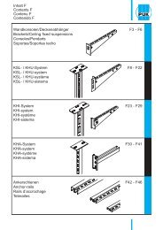
Contents A<br />
Screed flush duct systems<br />
Screed flush duct<br />
A5 - A8<br />
Heavy-duty floor duct<br />
A11 - A14
Screed flush duct systems<br />
Index<br />
Article Description Page Article Description Page<br />
UBK bottom piece A11<br />
UBKAB outward profile bend A13<br />
UBKD dummy cover A11<br />
UBKDB spacer A14<br />
UBKEB end piece A13<br />
UBKIB inward profile bend A13<br />
UBKPR side profile A12<br />
UBKPRV coupler A14<br />
UBKPRVE coupler A14<br />
UBKS screed flush heavy-duty duct, 1 compartment A11<br />
UBKTR barrier strip A14<br />
UBKV coupler A14<br />
UEBK screed flush duct, 1 compartment A5<br />
UEBKD dummy cover A8<br />
UEBKDA R assembly cover, round A5<br />
UEBKDA V assembly cover, quadrangular A5<br />
UEBKEA screed anchor A8<br />
UEBKEB end piece A6<br />
UEBKMA mounting Kit T-branch A6<br />
UEBKMB mounting Kit 90° bend A6<br />
UEBKPR side profile A8<br />
UEBKPT carpet flange A8<br />
UEBKSN height of mounting kit, Screed flush duct A6<br />
UEBKST levelling support A7<br />
UEBKT transverse cross bar A7<br />
UEBKTR barrier strip A8<br />
UEBKV coupler A7<br />
UEBKV S coupler A7<br />
UEBKVE S coupler A7
Screed flush duct systems<br />
Exploded view<br />
UEBKT<br />
UBKPRV<br />
UEBKD<br />
UEBKPT<br />
UEBKEB<br />
UBKDB<br />
UBKAB<br />
UBKV<br />
UEBKV<br />
UBKD<br />
UBKTR<br />
UBKIB<br />
UEBKVE<br />
UBK<br />
UBKEB<br />
UEBKST<br />
UEBKEA<br />
UEBKDA
Screed flush duct systems<br />
Screed flush duct
Screed flush duct systems<br />
Screed flush duct<br />
Hmin N B L Pmax E t<br />
mm mm mm mm kg kN mm mm<br />
UEBK<br />
screed flush duct, 1 compartment<br />
AL S<br />
UEBK 60-20S 60 + 50 200 2400 22,20 1,50 3<br />
UEBK 60-30S 60 + 50 300 2400 26,70 1,50 3<br />
UEBK 60-40S 60 + 50 400 2400 33,00 1,50 4<br />
Hmin<br />
B<br />
Pmax<br />
L<br />
inkl. 3 x UEBKT A7<br />
6 x UEBKST A7<br />
3 x UEBKD A8<br />
6 x UEBKEA A8<br />
2 x UEBKPR A8<br />
2 x UEBKPT A8<br />
UEBKV S A7<br />
UN<br />
B21<br />
Pmax<br />
B1<br />
t<br />
B2<br />
B3<br />
B4<br />
B1 B2 B3 B4<br />
UEBK 60-20S 230 160 203 330<br />
UEBK 60-30S 330 260 303 430<br />
UEBK 60-40S 430 360 403 530<br />
UEBKDA V<br />
assembly cover, quadrangular<br />
t<br />
B<br />
E<br />
L<br />
S<br />
UEBKDA-185V 20S 200 800 1,70 185x260 3<br />
UEBKDA-185V 30S 300 800 2,60 185x260 3<br />
UEBKDA-185V 40S 400 800 3,60 185x260 4<br />
UEBKDA-260V 30S 300 800 2,50 260x260 3<br />
UEBKDA-260V 40S 400 800 3,50 260x260 4<br />
UDKSEB C52<br />
UEBKDA R<br />
assembly cover, round<br />
S<br />
UEBKDA-260R 30S 300 800 2,5 260 3<br />
UEBKDA-260R 40S 400 800 3,5 260 4<br />
t<br />
B<br />
E<br />
L<br />
UDKSEB C52<br />
Assembly instructions, see page E10.<br />
A5
Screed flush duct systems<br />
Screed flush duct Mounting kit<br />
Hmin N B L<br />
mm mm mm mm kg<br />
UEBKSN<br />
height of mounting kit, screed flush duct<br />
S<br />
UEBKSN 135S 110 + 25 2400 2,70<br />
UEBKSN 155S 130 + 25 2400 3,30<br />
Hmin<br />
L<br />
inkl. 2 x UEBKPR A8<br />
6 x UKS M8x150 C56<br />
UEBKMA<br />
mounting Kit T-branch<br />
S<br />
UEBKMA 60-20S 60 + 50 1,60<br />
UEBKMA 60-30S 60 + 50 1,80<br />
UEBKMA 60-40S 60 + 50 2,00<br />
inkl. 2 x UEBKV A7<br />
2 x UEBKVE S A7<br />
2 x UEBKT A7<br />
3 x UEBKST A7<br />
UN B21<br />
UEBKMB<br />
mounting Kit 90° bend<br />
S<br />
UEBKMB 60-20S 60 + 50 2,95<br />
UEBKMB 60-30S 60 + 50 3,35<br />
UEBKMB 60-40S 60 + 50 3,70<br />
inkl. 1 x UEBKV A7<br />
1 x UEBKV S A7<br />
1 x UEBKVE S A7<br />
1 x UEBKT A7<br />
1 x UEBKEB A6<br />
3 x UEBKST A7<br />
UN B21<br />
UEBKEB<br />
end piece<br />
B<br />
Hmin<br />
AL<br />
UEBKEB 60-20S 60 + 50 200 1,90<br />
UEBKEB 60-30S 60 + 50 300 2,10<br />
UEBKEB 60-40S 60 + 50 400 2,30<br />
inkl. 1 x UEBKST A7<br />
2 x UEBKV A7<br />
UN B21<br />
A6<br />
Assembly instructions, see page E10.
Screed flush duct systems<br />
Screed flush duct Accessories<br />
Hmin N B<br />
mm mm mm kg<br />
UEBKV<br />
coupler<br />
PP<br />
UEBKV 0,05<br />
UEBKVE S<br />
coupler<br />
S<br />
UEBKVE S 0,05<br />
UEBKV S<br />
coupler<br />
S<br />
UEBKV S 0,05<br />
UEBKST<br />
levelling support<br />
AL S<br />
UEBKST 55 + 60 0,30<br />
Hmin<br />
UN B21<br />
UEBKT<br />
transverse cross bar<br />
S<br />
UEBKT 20 200 0,30<br />
UEBKT 30 300 0,50<br />
UEBKT 40 400 0,70<br />
B-25<br />
GB KB-G7<br />
A7
Screed flush duct systems<br />
Screed flush duct Accessories<br />
H B L H1 H2<br />
mm mm mm kg mm mm<br />
UEBKD<br />
dummy cover<br />
B<br />
L<br />
S<br />
UEBKD 20S 200 800 3,70<br />
UEBKD 30S 300 800 5,50<br />
UEBKD 40S 400 800 7,40<br />
inkl. 4 x BSS 4.8x22 D35<br />
UEBKTR<br />
barrier strip<br />
S<br />
UEBKTR 60S 50 3000 2,00<br />
UEBKTR 85S 80 3000 2,70<br />
H<br />
L<br />
SNA B21<br />
UEBKPR<br />
side profile<br />
S<br />
UEBKPR 135S 90 30 2400 1,20<br />
UEBKPR 155S 110 30 2400 1,50<br />
H<br />
B<br />
L<br />
PVC<br />
UEBKPR 60 40 2400 0,90<br />
UEBKPT<br />
carpet flange<br />
PVC<br />
UEBKPT 12 2400 0,30 7 3<br />
H2<br />
H1<br />
H<br />
L<br />
UEBKEA<br />
screed anchor<br />
PP<br />
UEBKEA 0,01<br />
A8
Screed flush duct systems<br />
Notes
Screed flush duct systems<br />
Heavy-duty floor duct
Screed flush duct systems<br />
Heavy-duty floor duct<br />
H B L Pmax t<br />
mm mm mm kg kN mm<br />
UBKS<br />
screed flush heavy-duty duct, 1 compartment<br />
S F<br />
The screed flush heavy-duty duct consists of the following parts: 1x heavy-duty<br />
duct bottom piece UBK; 3x heavy-duty dummy covers UBKD; 2x<br />
side profiles UBKPR with appropriate installation and connection materials.<br />
Other dimensions on request.<br />
UBK<br />
bottom piece<br />
H<br />
S<br />
UBK 100-20S 90 194 3000 17,2<br />
UBK 100-30S 90 294 3000 21,9<br />
UBK 100-40S 90 394 3000 26,9<br />
UBK 135-20S 125 194 3000 18,8<br />
UBK 135-30S 125 294 3000 25,2<br />
UBK 135-40S 125 394 3000 30,0<br />
UBK 170-20S 160 194 3000 23,8<br />
UBK 170-30S 160 294 3000 28,5<br />
UBK 170-40S 160 394 3000 33,3<br />
B<br />
L<br />
UBKD A11<br />
UBKPR<br />
A12<br />
UBKV<br />
A14<br />
UBKDB<br />
A14<br />
SNA<br />
B21<br />
UBKD<br />
dummy cover<br />
B<br />
L<br />
F<br />
UBKD5 25F 238 1000 9,8 5 5<br />
UBKD5 35F 338 1000 13,7 5 5<br />
UBKD5 45F 438 1000 17,7 5 5<br />
UBKD8 25F 250 1000 15,7 15 8<br />
UBKD8 35F 350 1000 22,0 15 8<br />
UBKD8 45F 450 1000 28,3 15 8<br />
UBKD10 25F 250 1000 19,7 25 10<br />
UBKD10 35F 350 1000 27,5 25 10<br />
UBKD10 45F 450 1000 35,4 25 10<br />
Assembly instructions, see page E15.<br />
A11
Screed flush duct systems<br />
Screed flush duct<br />
H B L T<br />
mm mm mm kg mm<br />
UBKPR<br />
side profile<br />
F<br />
UBKPR5F 45 40 3000 10,8 5<br />
UBKPR8F 57 50 3000 14,6 8<br />
UBKPR10F 60 50 3000 18,3 10<br />
L<br />
inkl. 1 x UBKPRV A14<br />
5 x FRS 8x25 KB-G8<br />
5 x SEMS 8 KB-G11<br />
UGD20 C55<br />
A12
Screed flush duct systems<br />
Heavy-duty floor duct Fittings<br />
H B L<br />
mm mm mm kg<br />
UBKEB<br />
end piece<br />
H<br />
B<br />
S<br />
UBKEB 100-20S 86 188 0,4<br />
UBKEB 100-30S 86 288 0,6<br />
UBKEB 100-40S 86 388 0,7<br />
UBKEB 135-20S 121 188 0,6<br />
UBKEB 135-30S 121 288 0,8<br />
UBKEB 135-40S 121 388 1,0<br />
UBKEB 170-20S 156 188 0,8<br />
UBKEB 170-30S 156 288 1,1<br />
UBKEB 170-40S 156 388 1,3<br />
KLS KB-G8<br />
UBKIB<br />
inward profile bend<br />
L<br />
UBKAB<br />
outward profile bend<br />
F<br />
UBKIB5F 300 2,5<br />
UBKIB8F 300 3,0<br />
UBKIB10F 300 3,6<br />
inkl. 1 x UBKPRV A14<br />
4 x FRS 8x25 KB-G8<br />
4 x SEMS 8 KB-G11<br />
F<br />
UBKAB5F 300 2,5<br />
UBKAB8F 300 3,1<br />
UBKAB10F 300 3,7<br />
L<br />
inkl. 1 x UBKPRV A14<br />
1 x UBKPRVE A14<br />
4 x SEMS 8 KB-G11<br />
4 x FRS 8x25 KB-G8<br />
A13
Screed flush duct systems<br />
Heavy-duty floor duct<br />
Accessories<br />
H B L t<br />
mm mm mm kg mm<br />
UBKV<br />
coupler<br />
t<br />
H<br />
S<br />
UBKV 100S 60 230 0,21 2<br />
UBKV 135S 95 230 0,34 2<br />
UBKV 170S 130 230 0,46 2<br />
L<br />
inkl. 2 x FRS 8x25 KB-G8<br />
2 x SEMS 8 KB-G11<br />
UBKPRV<br />
coupler<br />
t<br />
H<br />
S<br />
UBKPRV 35 150 0,16 3<br />
L<br />
UBKPRVE<br />
coupler<br />
t<br />
H<br />
S<br />
UBKPRVE 30 90 0,20 3<br />
L<br />
UBKDB<br />
spacer<br />
B<br />
t<br />
F<br />
UBKDB5 25F 242 0,25 5<br />
UBKDB5 35F 342 0,35 5<br />
UBKDB5 45F 442 0,45 5<br />
UBKDB8 25F 254 0,27 5<br />
UBKDB8 35F 354 0,37 5<br />
UBKDB8 45F 454 0,57 5<br />
UBKTR<br />
barrier strip<br />
L<br />
S<br />
UBKTR 100S 80 3000 6,3 1<br />
UBKTR 135S 115 3000 8,2 1<br />
UBKTR 170S 150 3000 10,1 1<br />
H<br />
SNA B21<br />
t<br />
A14
Contents B<br />
Floor trunking systems<br />
Floor trunking<br />
B5 - B7<br />
Hollow space floor box<br />
B9 - B12<br />
Cable duct<br />
B15 - B17<br />
Shuttering unit<br />
B19<br />
Accessories<br />
B21
Floor trunking systems<br />
Index<br />
Article Description Page Article Description Page<br />
SNA nail plug B21<br />
UB clip B5<br />
UBDEL grounding lug B21<br />
UBDHB 122R hollow-space floor box, single, round B12<br />
UBDHB Z grounding clamp B21<br />
UBDHB190 1R hollow-space floor box, single, round B12<br />
UBDHB190 1V hollow space floor box single, quadrangular B11<br />
UBDHB250 2R hollow space floor box double, round B10<br />
UBDHB250 2V hollow space floor box double, quadrangular B11<br />
UBDHB250 3V hollow space floor box triple, quadrangular B10<br />
UBDHB350 3R hollow space floor box triple, round B9<br />
UBDHB350 3V hollow space floor box triple, quadrangular B9<br />
UBKM bitumen glue B21<br />
UBRS channel partition - fire resistant B7<br />
UE end piece B7<br />
UGKB protection strip B21<br />
UK screed covered duct, 2 compartments B5<br />
UKAZ extension accessories B17<br />
UKD dummy cover for cable duct B15<br />
UKDA 185V cable duct assembly cover, quadrangular B16<br />
UKDA 260R cable duct assembly cover, round B16<br />
UKDA 260V cable duct assembly cover, quadrangular B16<br />
UKDA 308R cable duct assembly cover, round B16<br />
UKEB end piece B17<br />
UKL screed covered duct, 3 compartments B5<br />
UKR 2 cable duct bottom piece 2 compartments B15<br />
UKR 3 cable duct bottom piece 3 compartments B15<br />
UKR S screed-covered cable duct B15<br />
UKTR barrier strip B17<br />
UM mounting sleeve B6<br />
UN nail plug B21<br />
USK shuttering unit quadrangular B19<br />
USKH heat-resistant formwork element, quadrangular B19<br />
USKR formwork element, round B19<br />
USR shuttering tube B19<br />
USRH heat-resistant formwork pipe, round B19<br />
UVB 2 vertical bend, 2 partitions B6<br />
UVB 3 vertical bend, 3 partitions B6
Floor trunking systems<br />
Exploded view<br />
USK 160<br />
USR 308<br />
USK 259<br />
UVB 2<br />
UBDHB190 1V<br />
UBDHB350 3R<br />
UB<br />
UK<br />
UE<br />
UK<br />
UBDHB350 3V<br />
USR 308<br />
UKD<br />
UKDA R<br />
USK 259<br />
UKDA V<br />
UKTR<br />
UKAZ<br />
UKR 3<br />
UKEB
Floor trunking systems<br />
Floor trunking
Floor trunking systems<br />
Floor trunking<br />
H B L B1 B2 Pmax<br />
mm mm mm kg mm mm kN<br />
UK<br />
screed covered duct, 2 compartments<br />
S<br />
UK 2-28-190S 28 190 3000 15,5 95 95 0,75<br />
UK 2-28-250S 28 250 3000 19,0 125 125 0,75<br />
UK 2-28-350S 28 350 3000 24,7 175 175 0,75<br />
UK 2-38-190S 38 190 3000 16,5 95 95 0,75<br />
UK 2-38-250S 38 250 3000 19,8 125 125 0,75<br />
UK 2-38-350S 38 350 3000 25,5 175 175 0,75<br />
L<br />
UK 2-48-190S 48 190 3000 17,3 95 95 0,75<br />
UK 2-48-250S 48 250 3000 20,7 125 125 0,75<br />
UK 2-48-350S 48 350 3000 26,8 175 175 0,75<br />
UB B5<br />
UGKB<br />
B21<br />
UN<br />
B21<br />
UKL<br />
screed covered duct, 3 compartments<br />
S<br />
UKL 3-28-250S 28 250 3000 17,9 82 84 0,75<br />
UKL 3-28-350S 28 350 3000 23,3 116 116 0,75<br />
UKL 3-38-250S 38 250 3000 18,7 82 84 0,75<br />
UKL 3-38-350S 38 350 3000 24,2 115 116 0,75<br />
L<br />
UKL 3-48-250S 48 250 3000 19,7 82 84 0,75<br />
UKL 3-48-350S 48 350 3000 25,1 115 116 0,75<br />
UB B5<br />
UGKB<br />
B21<br />
UN<br />
B21<br />
UB<br />
clip<br />
H<br />
B<br />
L<br />
S<br />
UB 28-190S 28 194 42 0,09<br />
UB 28-250S 28 254 42 0,11<br />
UB 28-350S 28 354 42 0,14<br />
UB 38-190S 38 194 42 0,10<br />
UB 38-250S 38 254 42 0,12<br />
UB 38-350S 38 354 42 0,15<br />
UB 48-190S 48 194 42 0,10<br />
UB 48-250S 48 254 42 0,12<br />
UB 48-350S 48 354 42 0,16<br />
UN B21<br />
Other dimensions on request.<br />
B5
Floor trunking systems<br />
Floor trunking<br />
H B L<br />
mm mm mm kg<br />
UVB 2<br />
vertical bend, 2 partitions<br />
H<br />
B<br />
L<br />
S<br />
UVB 2-28-190S 29 186 132 1,16<br />
UVB 2-28-250S 29 246 132 1,39<br />
UVB 2-28-350S 29 346 132 1,95<br />
UVB 2-38-190S 39 186 132 1,31<br />
UVB 2-38-250S 39 246 132 1,50<br />
UVB 2-38-350S 39 346 132 2,05<br />
UVB 2-48-190S 49 186 132 1,46<br />
UVB 2-48-250S 49 246 132 1,75<br />
UVB 2-48-350S 49 346 132 2,20<br />
UB B5<br />
UN<br />
B21<br />
UVB 3<br />
vertical bend, 3 partitions<br />
H<br />
S<br />
UVB 3-28-250S 29 246 132 1,55<br />
UVB 3-28-350S 29 346 132 2,20<br />
UVB 3-38-250S 39 246 132 1,70<br />
UVB 3-38-350S 39 346 132 2,40<br />
UVB 3-48-250S 49 246 132 1,95<br />
UVB 3-48-350S 49 346 132 2,60<br />
B<br />
L<br />
UB B5<br />
UN<br />
B21<br />
UM<br />
mounting sleeve<br />
H<br />
B<br />
62 mm<br />
L<br />
S<br />
UM 28-190S 28 194 82 0,55<br />
UM 28-250S 28 254 82 0,64<br />
UM 28-350S 28 354 82 0,80<br />
UM 38-190S 38 194 82 0,56<br />
UM 38-250S 38 254 82 0,66<br />
UM 38-350S 38 354 82 0,82<br />
UM 48-190S 48 194 82 0,58<br />
UM 48-250S 48 254 82 0,68<br />
UM 48-350S 48 354 82 0,84<br />
UN B21<br />
B6
Floor trunking systems<br />
Floor trunking<br />
H B L<br />
mm mm mm kg<br />
UE<br />
end piece<br />
H<br />
B<br />
S<br />
UE 28-350S 26 347 0,14<br />
UE 38-350S 36 347 0,17<br />
UE 48-350S 46 347 0,20<br />
UBRS<br />
channel partition - fire resistant<br />
S<br />
UBRS 38-350S 55 380 270 2,40<br />
H<br />
UN B21<br />
B<br />
20 mm<br />
L<br />
Other dimensions on request.<br />
B7
Floor trunking systems<br />
Hollow space floor box
Floor trunking systems<br />
Hollow space floor box<br />
H Hmin B1 L1 B2 L2 E<br />
mm mm mm mm kg mm mm mm<br />
UBDHB350 3V<br />
hollow space floor box triple, quadrangular<br />
S<br />
UBDHB350 28-259V 31 67 410 410 3,9 450 450 262<br />
UBDHB350 38-259V 41 77 410 410 4,0 450 450 262<br />
UBDHB350 48-259V 51 87 410 410 4,1 450 450 262<br />
USK B19<br />
UN<br />
B21<br />
UBDHB350 3R<br />
hollow space floor box triple, round<br />
S<br />
UBDHB350 28-308R 31 67 410 410 3,4 450 450 310<br />
UBDHB350 38-308R 41 77 410 410 3,5 450 450 310<br />
UBDHB350 48-308R 51 87 410 410 3,6 450 450 310<br />
USR B19<br />
UN<br />
B21<br />
Assembly instructions, see page E18 / E20.<br />
B9
Floor trunking systems<br />
Hollow space floor box<br />
H Hmin B1 L1 B2 L2 E<br />
mm mm mm mm kg mm mm mm<br />
UBDHB250 3V<br />
hollow space floor box triple, quadrangular<br />
S<br />
UBDHB250 28-259V 31 76 385 385 3,3 400 400 262<br />
UBDHB250 38-259V 41 77 385 385 3,4 400 400 262<br />
UBDHB250 48-259V 51 87 385 385 3,5 400 400 262<br />
USK B19<br />
UN<br />
B21<br />
UBDHB250 2R<br />
hollow space floor box double, round<br />
S<br />
UBDHB250 28-259R 31 67 385 385 3,1 400 400 260<br />
UBDHB250 38-259R 41 77 385 385 3,2 400 400 260<br />
UBDHB250 48-259R 51 87 385 385 3,3 400 400 260<br />
USR B19<br />
UN<br />
B21<br />
B10<br />
Assembly instructions, see page E18 / E20.
Floor trunking systems<br />
Hollow space floor box<br />
H Hmin B1 L1 B2 L2 E<br />
mm mm mm mm kg mm mm mm<br />
UBDHB250 2V<br />
hollow space floor box double, quadrangular<br />
S<br />
UBDHB250 28-185V 31 67 385 385 3,5 400 400 187x262<br />
UBDHB250 38-185V 41 77 385 385 3,6 400 400 187x262<br />
UBDHB250 48-185V 51 87 385 385 3,7 400 400 187x262<br />
USK B19<br />
UN<br />
B21<br />
UBDHB190 1V<br />
hollow space floor box single, quadrangular<br />
S<br />
UBDHB190 28-160V 31 67 270 270 1,2 290 290 165<br />
UBDHB190 38-160V 41 77 270 270 1,9 290 290 165<br />
UBDHB190 48-160V 51 87 270 270 2,0 290 290 165<br />
USK B19<br />
UN<br />
B21<br />
Assembly instructions, see page E18 / E20.<br />
B11
Floor trunking systems<br />
Hollow space floor box<br />
H Hmin B1 L1 B2 L2 E<br />
mm mm mm mm kg mm mm mm<br />
UBDHB190 1R<br />
hollow-space floor box, single, round<br />
S<br />
UBDHB190 28-122R 31 67 270 270 1,6 290 290 123<br />
UBDHB190 38-122R 41 77 270 270 1,7 290 290 123<br />
UBDHB190 48-122R 51 87 270 270 1,8 290 290 123<br />
USKR B19<br />
UN<br />
B21<br />
UBDHB 122R<br />
hollow-space floor box, single, round<br />
S<br />
UBDHB 38-122R 42 73 150 150 0,6 160 160 123<br />
USKR B19<br />
UN<br />
B21<br />
B12<br />
Assembly instructions, see page E18 / E20.
Floor trunking systems<br />
Notes
Floor trunking systems<br />
Cable duct
Floor trunking systems<br />
Cable duct<br />
H B L Pmax<br />
mm mm mm kg kN<br />
UKR S<br />
screed-covered cable duct<br />
S<br />
The screed-covered cable duct includes the following components:<br />
1x lower part of cable duct UKR, 1x cable duct dummy lid UKD and<br />
1x and/or 2x separating strip UKTR with corresponding installation and<br />
connection materials.<br />
UKR 2<br />
cable duct bottom piece 2 compartments<br />
S<br />
UKR 35-30S 35 300 3000 8,9<br />
inkl. 1 x UKTR B17<br />
3 x SNA 6x30/5 B21<br />
H<br />
VB KB-B21<br />
B<br />
L<br />
UKR 3<br />
cable duct bottom piece 3 compartments<br />
H<br />
S<br />
UKR 35-40S 35 400 3000 14,2<br />
UKR 35-50S 35 500 3000 15,4<br />
UKR 60-40S 60 400 3000 19,8<br />
UKR 60-50S 60 500 3000 23,9<br />
UKR 85-40S 85 400 3000 23,4<br />
UKR 85-50S 85 500 3000 27,5<br />
UKR 110-40S 110 400 3000 28,7<br />
UKR 110-50S 110 500 3000 31,0<br />
B<br />
L<br />
inkl. 2 x UKTR B17<br />
6 x SNA 6x30/5 B21<br />
VB KB-B21<br />
UKD<br />
dummy cover for cable duct<br />
Pmax<br />
S<br />
UKD 30S 300 3000 7,9 0,75<br />
UKD 40S 400 3000 10,2 0,75<br />
UKD 50S 500 3000 19,0 0,75<br />
B<br />
L<br />
Assembly instructions, see page E22.<br />
B15
Floor trunking systems<br />
Cable duct<br />
B L Pmax E<br />
mm mm kg kN mm<br />
UKDA 308R<br />
cable duct assembly cover, round<br />
Pmax<br />
S<br />
UKDA-308R 40S 400 495 2,3 0,75 Ø 310<br />
UKDA-308R 50S 500 595 3,9 0,75 Ø 310<br />
E<br />
USR B19<br />
UBDEL<br />
B21<br />
B<br />
L<br />
UKDA 260R<br />
cable duct assembly cover, round<br />
Pmax<br />
S<br />
UKDA-260R 30S 300 420 1,2 0,75 Ø 260<br />
UKDA-260R 40S 400 495 2,1 0,75 Ø 260<br />
UKDA-260R 50S 500 595 4,4 0,75 Ø 260<br />
B<br />
E<br />
L<br />
USR B19<br />
UBDEL<br />
B21<br />
UKDA 260V<br />
cable duct assembly cover, quadrangular<br />
Pmax<br />
S<br />
UKDA-260V 40S 400 495 2,0 0,75 262<br />
UKDA-260V 50S 500 595 3,3 0,75 262<br />
B<br />
E<br />
L<br />
USR B19<br />
UBDEL<br />
B21<br />
UKDA 185V<br />
cable duct assembly cover, quadrangular<br />
Pmax<br />
E<br />
S<br />
UKDA-185V 30S 300 420 1,3 0,75 262x187<br />
UKDA-185V 40S 400 495 2,2 0,75 262x187<br />
UKDA-185V 50S 500 595 3,4 0,75 262x187<br />
B<br />
L<br />
USK B19<br />
UBDEL<br />
B21<br />
B16<br />
Assembly instructions, see page E22.
Floor trunking systems<br />
Cable duct<br />
H B L<br />
mm mm mm kg<br />
UKEB<br />
end piece<br />
H<br />
B<br />
S<br />
UKEB 35-30S 35 300 0,13<br />
UKEB 35-40S 35 400 0,16<br />
UKEB 35-50S 35 500 0,19<br />
UKEB 60-40S 60 400 0,31<br />
UKEB 60-50S 60 500 0,36<br />
inkl. 1 x KLR KB-G3<br />
UKEB 85-40S 85 400 0,64<br />
UKEB 85-50S 85 500 0,75<br />
UKEB 110-40S 115 400 0,93<br />
UKEB 110-50S 115 500 1,10<br />
inkl. 2 x KLR KB-G3<br />
UKAZ<br />
extension accessories<br />
B<br />
S<br />
UKAZ 35-30S 35 300 0,4<br />
UKAZ 35-40S 35 400 0,5<br />
UKAZ 35-50S 35 500 0,6<br />
UKAZ 60-40S 60 400 1,2<br />
UKAZ 60-50S 60 500 1,3<br />
H<br />
inkl. 2 x SNA 6x30/5 B21<br />
2 x KLR KB-G3<br />
UKAZ 85-40S 85 400 1,4<br />
UKAZ 85-50S 85 500 1,6<br />
UKAZ 110-40S 110 400 1,7<br />
UKAZ 110-50S 110 500 1,8<br />
inkl. 2 x SNA 6x30/5 B21<br />
4 x KLR KB-G3<br />
UKTR<br />
barrier strip<br />
S<br />
UKTR 35S 33 3000 1,6<br />
UKTR 60S 57 3000 2,1<br />
UKTR 85S 80 3000 2,8<br />
UKTR 110 107 3000 4,8<br />
H<br />
L<br />
SNA B21<br />
Assembly instructions, see page E22.<br />
B17
Floor trunking systems<br />
Shuttering unit
Floor trunking systems<br />
Shuttering unit<br />
H B L D TL Tmax<br />
mm mm mm kg mm mm °C<br />
USR<br />
shuttering tube<br />
D<br />
KT<br />
USR 308-150 150 0,42 308<br />
USR 308-225 225 0,60 308<br />
USR 259-150 150 0,30 260<br />
H<br />
USKR<br />
formwork element, round<br />
D<br />
STY<br />
USK 120R-150 150 0,42 122<br />
H<br />
USK<br />
shuttering unit quadrangular<br />
H<br />
STY<br />
USK 259V-150 150 261 261 0,19<br />
USK 259V-225 225 261 261 0,24<br />
USK 185V-150 150 261 186 0,16<br />
USK 160V-150 150 164 164 0,14<br />
B<br />
L<br />
USRH<br />
heat-resistant formwork pipe, round<br />
D<br />
S<br />
USRH 308-200 250 1,9 308 < 2 250<br />
H<br />
USKH<br />
heat-resistant formwork element, quadrangular<br />
H<br />
USKH 259V-200 200 261 261 2,9 < 2 250<br />
H<br />
B<br />
L<br />
Assembly instructions, see page E18 / E20.<br />
B19
Floor trunking systems<br />
Accessories
Floor trunking systems<br />
Accessories<br />
L<br />
mm<br />
kg<br />
UN<br />
nail plug<br />
Z<br />
UN 5/38 < 0,01<br />
SNA<br />
nail plug<br />
Z<br />
SNA 6x30/5 0,02<br />
UGKB<br />
protection strip<br />
PET<br />
UGKB 50000 0,40<br />
L<br />
UBKM<br />
bitumen glue<br />
UBKM < 0,50<br />
BITUMEN<br />
BITUMEN<br />
BITUMEN<br />
UBDEL<br />
grounding lug<br />
S<br />
UBDEL < 0,01<br />
UBDHB Z<br />
grounding clamp<br />
S<br />
UBDHB-Z < 0,01<br />
B21
Floor trunking systems<br />
Notes
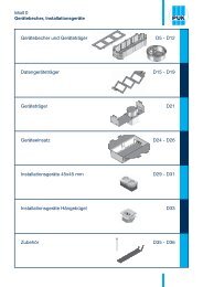
Contents C<br />
Installation units for screed and hollow floors<br />
Installation unit made of plastic<br />
C5 - C8<br />
Installation unit made of<br />
high-grade steel<br />
C11 - C24<br />
Single outlet<br />
C28 - C37<br />
Plug-in connector systems<br />
C40 - C45<br />
Accessories plastic units<br />
C47 - C50<br />
Accessories high-grade steel<br />
cartridges<br />
C51 - C54
Installation units for screed and hollow floors<br />
Index<br />
Article Description Page Article Description Page<br />
BODO N single-outlet with floor socket outlet, wet maintenance, round C30<br />
BODO NL single-outlet, wet maintenance, round, empty C30<br />
BODO T single-outlet with floor socket outlet, dry maintenance, round C31<br />
BODO TL single-outlet, dry maintenance, round, empty C31<br />
UBDSLF levelling support C56<br />
UBP V dummy unit, triple, quadrangular C18<br />
UDBS 40-80 claw for plastic dummy cover C52<br />
UDBS R 4 hollow space floor claw for dummy cover, round C52<br />
UDBS R 6 hollow space floor claw for dummy cover, round C52<br />
UDBS V 4 hollow space floor claw for dummy cover, quadrangular C52<br />
UDKS 40-80 claw for plastic hinged cover C52<br />
UDKS R 4 hollow space floor claws for hinged cover, round C51<br />
UDKS R 6 hollow space floor claws for hinged cover, round C51<br />
UDKS V 4 hollow space floor claws for hinged cover, quadrangular C51<br />
UDKSEB claw, screed flush C52<br />
UEBD 5 V E dummy cartridge triple, quadrangular C18<br />
UEBD R cover inlay, dummy cover, round C49<br />
UEBD R E triple dummy cartridge unit, round, levellable C11<br />
UEBD V cover inlay, dummy cover, quadrangular C49<br />
UEBD V E triple dummy cartridge unit, quadrangular C15<br />
UEBD1-1 V E dummy single-outlet cartridge, quadrangular, levellable C34<br />
UEBD1-2 V E dummy single-outlet cartridge, quadrangular, levellable C37<br />
UEBD1-4 V E single-outlet cartridge, dummy-type, 2x, quadrangular,<br />
levellable<br />
C35<br />
UEBD2 R installation unit - dummy cover double, round C5<br />
UEBD2 V assembly unit - dummy cover - double, quadrangular C7<br />
UEBD2 V E dummy cartridge unit double, quadrangular, levellable C19<br />
UEBD3 R installation unit - dummy cover triple, round C5<br />
UEBD3 V installation unit - dummy cover triple, quadrangular C7<br />
UEBDD V E dummy cartridge installation unit, triple, quadrangular C24<br />
UEBDD2 V E cartridge installation unit dummy cover double, quadrangular C25<br />
UEBDE R cover insert, high-grade steel dummy cartridge, triple C53<br />
UEBDE V cover insert, high-grade steel dummy cartridge, triple C53<br />
UEBDM R tube cartridge unit, triple, round, levellable C12<br />
UEBDM V tube-cartridge unit triple, quadrangular C16<br />
UEBDME R cover insert, tube outlet cartridge, triple C53<br />
UEBDME V cover insert, tube outlet cartridge, triple C53<br />
UEBDS R E heavy-duty dummy cartridge unit, triple, round, levellable C12<br />
UEBDS V E heavy-duty dummy cartridge unit, triple, quadrangular C16<br />
UEBDSM R heavy-duty tube-cartridge unit triple, round, levellable C13<br />
UEBDSM V heavy-duty tube-cartridge unit triple, quadrangular C17<br />
UEBDSM1-2 V heavy-duty tube single outlet cartridge, quadrangular,<br />
levellable<br />
C38<br />
UEBDSM1-4 V heavy-duty tube single outlet cartridge, quadrangular,<br />
levellable<br />
C36<br />
UEKA cable connection flap C51<br />
UEKB cable guiding block C51<br />
UEKD R cover inlay, hinged cover, round C49<br />
UEKD R E cartridge cover, triple, round, levellable C11<br />
UEKD V cover inlay, hinged cover, quadrangular C49<br />
UEKD V E cartridge unit - hinged cover triple, quadrangular C15<br />
UEKD1-1 V E single-outlet cable cartridge, one-piece, quadrangular,<br />
levellable<br />
C34<br />
UEKD1-2 V E cable single-outlet cartridge, quadrangular, levellable C37<br />
UEKD1-4 V E single-outlet cable cartridge, duplex, quadrangular, levellable C35<br />
UEKD2 R installation unit - hinged cover double, round C6<br />
UEKD2 V installation unit - hinged cover double, quadrangular C8<br />
UEKD2 V E cable outlet cartridge double, quadrangular, levellable C19<br />
UEKD3 R installation unit - hinged cover triple, round C6<br />
UEKD3 R 5K cover insert, plastic installation triple C49<br />
UEKD3 V installation unit - hinged cover triple, quadrangular C8<br />
UEKD3 V 5K cover insert, plastic installation triple C49<br />
UEKDD V E cartridge unit - hinged cover triple, quadrangular C24<br />
UEKDD1-2 V E cartridge unit - hinged cover single, quadrangular C26<br />
UEKDD2 V E cartridge unit - hinged cover double, quadrangular C25<br />
UEKDE R cover insert, high-grade steel cable outlet cartridge, triple C53<br />
UEKDE V cover insert, high-grade steel cable outlet cartridge, triple C53<br />
UEKDS R E heavy-duty cable outlet cartridge, triple, round, levellable C13<br />
UEKDS V E heavy-duty cable outlet cartridge, triple, quadrangular C17<br />
UEKH opening lever C51<br />
UET tube, wet-maintenance C54<br />
UET80 tube, wet-maintenance C57<br />
UETD tube cover C54<br />
UETD80 tube cover C57<br />
UG2 device mounting cup C45<br />
UG2-1 device mounting cup C45<br />
UG2-2 device mounting cup C45<br />
UG3 device mounting cup C45<br />
UG3-1 device mounting cup C45<br />
UG4 device mounting cup C45<br />
UG45WA-2 device mounting cup, WAGO C44<br />
UG45WA-2-1 device mounting cup, WAGO<br />
C44<br />
UG45WA-2-2 device mounting cup, WAGO<br />
C44<br />
UG45WA-3 device mounting cup, WAGO C44<br />
UG45WA-3-1 device mounting cup, WAGO<br />
C44<br />
UG45WA-4 device mounting cup, WAGO C44<br />
UG45WI-2 device mounting cup, Wieland C46<br />
UG45WI-2-1 device mounting cup, Wieland C46<br />
UG45WI-2-2 device mounting cup, Wieland C46<br />
UG45WI-3 device mounting cup, Wieland C46<br />
UG45WI-3-1 device mounting cup, Wieland C46<br />
UG45WI-4 device mounting cup, Wieland C46<br />
UGD R rubber seal, round C55<br />
UGD V rubber seal, quadrangular C55<br />
UGD1-1 V rubber seal, quadrangular C58<br />
UGD1-2 V rubber seal, quadrangular C58<br />
UGD2 V rubber seal, quadrangular C55<br />
UGD20 rubber strips C55<br />
UGD3 V rubber seal, quadrangular C55<br />
UGDB15 rubber seal, round C55<br />
UGEA retrofit kit for device cup C50<br />
UGEAR set of registering leads, round C14<br />
UGEAR ELS grounding lug, round C56<br />
UGEARL registering extension, triple C50<br />
UGEAV set of registering leads, quadrangular C20<br />
UGEAV1-2 set of registering leads, quadrangular C39<br />
UGEAV2 set of registering leads, quadrangular C20<br />
UGM rubber sleeve C57<br />
UGM SLF subsonic noise sleeve socket - levelling support C56<br />
UGR1-4 device cup, round, pre-assembled C39<br />
UKDDB1-2 V E cartridge unit cable outlet quadrangular, dummy-type C26<br />
UKS phillips screw C56<br />
ULS R sealing bag C50<br />
UNE levelling unit dummy, triple, quadrangular C18<br />
USH B siphon C56<br />
USK R shuttering round C50<br />
USK R122 shuttering round C57<br />
USK V shuttering, quadrangular C50<br />
UV distributor box C42<br />
UVA connector lead plug - open end C47<br />
UVA GB grounding line C54<br />
UVA GB1 grounding line C54<br />
UVABU connecting line plug - socket C47<br />
UVB-2 distributor block C42<br />
UVB-5 distributor block C42<br />
UVBU socket component C42<br />
UVS BU snap-in-piece, socket, Wago C43<br />
UVS ST snap-in-piece, plug, Wago C43<br />
UVST plug component C42<br />
UVSWI ST snap-in-piece, plug, Wieland C43<br />
UWZ IS allen wrench C57<br />
UWZ TS torx key C57
Installation units for screed and hollow floors<br />
Exploded view<br />
UEBD3-R<br />
3x UG<br />
UEBD2-R<br />
2x UG<br />
UEKD3-R<br />
UEKD2-R<br />
USR 308 USR 259<br />
USK-R3<br />
USK-R<br />
UEBD3-V<br />
3x UG<br />
UEBD2-V<br />
2x UG<br />
UEKD3-V<br />
UEKD2-V<br />
USK 259 USK 185<br />
USK-V<br />
USK-V2
Installation units for screed and hollow floors<br />
Installation unit made of plastic
Installation units for screed and hollow floors<br />
Installation unit made of plastic Installation unit, round<br />
H Hmin B T Pmax E C<br />
mm mm mm kg mm kN mm RAL<br />
UEBD2 R<br />
installation unit - dummy cover double, round<br />
PA<br />
UEBD2-R-G 65 65 280 1,32 8 1,5 260 7011<br />
UEBD2-R-S 65 65 280 1,32 8 1,5 260 9011<br />
inkl. 1 x UDBS-R 4 C51<br />
UEBD R C49<br />
UEBD3 R<br />
installation unit - dummy cover triple, round<br />
PA<br />
UEBD3-R-G 65 65 330 1,87 8 1,5 307 7011<br />
UEBD3-R-S 65 65 330 1,87 8 1,5 307 9011<br />
inkl. 1 x UDBS-R 6 C51<br />
UEBD R C49<br />
C5
Installation units for screed and hollow floors<br />
Installation unit made of plastic Installation unit, round<br />
H Hmin B T Pmax E C<br />
mm mm mm kg mm kN mm RAL<br />
UEKD2 R<br />
installation unit - hinged cover double, round<br />
PA<br />
UEKD2-R-G 65 74 280 1,30 8 1,5 260 7011<br />
UEKD2-R-S 65 74 280 1,30 8 1,5 260 9011<br />
inkl. 1 x UDKS-R 4 C51<br />
UEKD R C49<br />
UEKD3 R<br />
installation unit - hinged cover triple, round<br />
PA<br />
UEKD3-R-G 65 74 330 1,84 8 1,5 307 7011<br />
UEKD3-R-S 65 74 330 1,84 8 1,5 307 9011<br />
inkl. 1 x UDKS-R 6 C51<br />
UEKD R C49<br />
UGEARL<br />
C50<br />
C6<br />
Assembly instructions, see page E25.
Installation units for screed and hollow floors<br />
Installation unit made of plastic Installation unit, quadrangular<br />
H Hmin B L T Pmax E C<br />
mm mm mm mm mm kg kN mm RAL<br />
UEBD2 V<br />
installation unit - dummy cover - double, quadrangular<br />
PA<br />
UEBD2-V-G 65 65 206 280 8 1,30 1,5 186x261 7011<br />
UEBD2-V-S 65 65 206 280 8 1,30 1,5 186x261 9011<br />
inkl. 1 x UDBS-V 4 C52<br />
UEBD V C49<br />
UEBD3 V<br />
installation unit - dummy cover triple, quadrangular<br />
PA<br />
UEBD3-V-G 65 65 280 280 8 1,50 1,5 261 7011<br />
UEBD3-V-S 65 65 280 280 8 1,50 1,5 261 9011<br />
inkl. 1 x UDBS-V 4 C52<br />
UEBD V C49<br />
C7
Installation units for screed and hollow floors<br />
Installation unit made of plastic Installation unit, quadrangular<br />
H Hmin B L T Pmax E C<br />
mm mm mm mm mm kg kN mm RAL<br />
UEKD2 V<br />
installation unit - hinged cover double, quadrangular<br />
PA<br />
UEKD2-V-G 65 74 206 280 8 1,40 1,5 186x261 7011<br />
UEKD2-V-S 65 74 206 280 8 1,40 1,5 186x261 9011<br />
inkl. 1 x UDKS-V 4 C52<br />
UEKD V C49<br />
UEKD3 V<br />
installation unit - hinged cover triple, quadrangular<br />
PA<br />
UEKD3-V-G 65 74 280 280 8 1,60 1,5 261 7011<br />
UEKD3-V-S 65 74 280 280 8 1,60 1,5 261 9011<br />
inkl. 1 x UDKS-V 4 C52<br />
UEKD V C49<br />
UGEARL<br />
C50<br />
C8<br />
Assembly instructions, see page E28.
Installation units for screed and hollow floors<br />
Exploded view<br />
UEBD R E<br />
UEKD R E<br />
UEBDS V E<br />
UEBDM R<br />
UEKDS V E<br />
UET<br />
UEBDSM V<br />
UEBDS R E<br />
UEBD V E<br />
UEKD V E<br />
UET<br />
UEKDS R E<br />
UEBDM V<br />
UEBDSM R<br />
UEBD2 V E<br />
UEKD2 V E<br />
UNE<br />
UGEAR<br />
UGEAV2<br />
UGEAV<br />
USK 185 USK 259<br />
USR 308
Installation units for screed and hollow floors<br />
Installation unit made of high-grade steel
Installation units for screed and hollow floors<br />
Installation unit made of high-grade steel cartridge unit, round<br />
H Hmin N B T Pmax E<br />
mm mm mm mm kg mm kN mm<br />
UEBD R E<br />
triple dummy cartridge unit, round, levellable<br />
E G<br />
UEBD 15-R E 21 100 + 55 305 3,14 12 2,0 307<br />
UEBD 35-R E 38 117 + 55 305 3,67 30 2,0 307<br />
inkl. 1 x UGDB15-R300 1.8 C55<br />
1 x UGEAR-ELS C56<br />
UEKD R E<br />
cartridge cover, triple, round, levellable<br />
E G<br />
UEKD 15-R E 21 100 + 55 305 3,20 12 2,0 307<br />
UEKD 35-R E 38 117 + 55 305 3,46 30 2,0 307<br />
inkl. 1 x UGD-R 10-2 C55<br />
UGEAR C14<br />
UEKDE R<br />
C53<br />
Assembly instructions, see page E31.<br />
C11
Installation units for screed and hollow floors<br />
Installation unit made of high-grade steel<br />
cartridge unit, round<br />
H Hmin N B T Pmax E t<br />
mm mm mm mm kg mm kN mm mm<br />
UEBDM R<br />
tube cartridge unit, triple, round, levellable<br />
AL E G<br />
UEBDM 15-R-WD 21 100 + 55 305 3,20 12 2,0 307<br />
UEBDM 35-R-WD 38 117 + 55 305 3,82 30 2,0 307<br />
inkl. 1 x UGDB15-R300 1.8 C55<br />
1 x UETD-R-WD C54<br />
UGEAR C14<br />
UET<br />
C54<br />
UEBDS R E<br />
heavy-duty dummy cartridge unit, triple, round,<br />
levellable<br />
E G<br />
UEBDS 35-R6 E 38 117 + 55 305 6,93 24 20 307 6<br />
inkl. 1 x UGDB15-R300 1.8 C55<br />
1 x UGEAR-ELS C56<br />
C12<br />
Assembly instructions, see page E31.
Installation units for screed and hollow floors<br />
Installation unit made of high-grade steel cartridge unit, round<br />
H Hmin N B T Pmax E t<br />
mm mm mm mm kg mm kN mm mm<br />
UEKDS R E<br />
heavy-duty cable outlet cartridge, triple, round,<br />
levellable<br />
E G<br />
UEKDS 35-R6 E 38 117 + 55 305 6,30 24 10 307 6<br />
inkl. 1 x UGD-R 10-2 C55<br />
UGEAR<br />
UEKDE R<br />
C14<br />
C49<br />
UEBDSM R<br />
heavy-duty tube-cartridge unit triple, round, levellable<br />
AL E G<br />
UEBDSM 35-R6-WD 36 115 +60 305 6,20 24 20 307 6<br />
inkl. 1 x UGDB15-R300 1.8 C55<br />
1 x UETD-R-WD C54<br />
UGEAR C14<br />
UET<br />
C54<br />
Assembly instructions, see page E31.<br />
C13
Installation units for screed and hollow floors<br />
Installation unit made of high-grade steel<br />
cartridge unit, round<br />
H Hmin B Rb<br />
mm mm mm kg mm<br />
UGEAR<br />
set of registering leads, round<br />
S<br />
UGEAR-50S 55 65 190 0,28 30<br />
UGEAR-80S 84 95 190 0,34 30<br />
H<br />
B<br />
C14
Installation units for screed and hollow floors<br />
Installation unit made of high-grade steel cartridge unit, quadrangular<br />
H Hmin B L T Pmax E<br />
mm mm mm mm kg mm kN mm<br />
UEBD V E<br />
triple dummy cartridge unit, quadrangular<br />
E G<br />
UEBD 15-V E 19 85 258 258 1,75 12 2,0 261<br />
UEBD 25-V E 29 95 258 258 1,98 22 2,0 261<br />
UEBD 35-V E 39 105 258 258 2,25 32 2,0 261<br />
UEBD 45-V E 49 115 258 258 2,51 42 2,0 261<br />
inkl. 1 x UGD3-V 2 C55<br />
4 x UKS M4x16E C56<br />
UNE C18<br />
UEKD V E<br />
cartridge unit - hinged cover triple, quadrangular<br />
E G<br />
UEKD 15-V E 19 85 258 258 1,80 12 2,0 261<br />
UEKD 25-V E 29 95 258 258 2,00 22 2,0 261<br />
UEKD 35-V E 39 105 258 258 2,20 32 2,0 261<br />
UEKD 45-V E 49 115 258 258 2,40 42 2,0 261<br />
inkl. 1 x UGD-V 2 C55<br />
4 x UKS M4x16E C56<br />
UNE C18<br />
UGEAV<br />
C20<br />
UEKDE V<br />
C53<br />
Assembly instructions, see page E31.<br />
C15
Installation units for screed and hollow floors<br />
Installation unit made of high-grade steel<br />
cartridge unit, quadrangular<br />
H Hmin B L T Pmax E t<br />
mm mm mm mm kg mm kN mm mm<br />
UEBDM V<br />
tube-cartridge unit triple, quadrangular<br />
AL E G<br />
UEBDM 15-V-WD 19 85 258 258 1,90 12 2,0 261<br />
UEBDM 25-V-WD 29 95 258 258 2,10 22 2,0 261<br />
UEBDM 35-V-WD 39 105 258 258 2,30 32 2,0 261<br />
UEBDM 45-V-WD 49 115 258 258 2,60 42 2,0 261<br />
inkl. 1 x UGD3-V 2 C55<br />
1 x UETD-R-WD C54<br />
4 x UKS M4x16E C56<br />
UNE C18<br />
UGEAV<br />
C20<br />
UET<br />
C54<br />
UEBDS V E<br />
heavy-duty dummy cartridge unit, triple, quadrangular<br />
E G<br />
UEBDS 25-V6 E 29 85 258 258 4,80 16 10 261 6<br />
UEBDS 35-V6 E 39 105 258 258 5,10 26 10 261 6<br />
UEBDS 45-V6 E 49 115 258 258 5,30 36 10 261 8<br />
UEBDS 35-V8 E 39 105 258 258 6,00 24 20 261 8<br />
UEBDS 45-V8 E 49 115 258 258 6,20 34 20 261 8<br />
inkl. 1 x UGD3-V 2 C55<br />
4 x UKS M4x16E C56<br />
UNE C18<br />
C16<br />
Assembly instructions, see page E31.
Installation units for screed and hollow floors<br />
Installation unit made of high-grade steel cartridge unit, quadrangular<br />
H Hmin B L T Pmax E t<br />
mm mm mm mm kg mm kN mm mm<br />
UEKDS V E<br />
heavy-duty cable outlet cartridge, triple, quadrangular<br />
E G<br />
UEKDS 25-V6 E 29 95 258 258 4,8 16 10 261 6<br />
UEKDS 35-V6 E 39 105 258 258 5,0 26 10 261 6<br />
UEKDS 45-V6 E 49 115 258 258 5,2 36 10 261 6<br />
inkl. 1 x UGD-V 2 C55<br />
4 x UKS M4x16E C56<br />
UNE C18<br />
UGEAV<br />
C20<br />
UEKDE V<br />
C53<br />
UEBDSM V<br />
heavy-duty tube-cartridge unit triple, quadrangular<br />
AL E G<br />
UEBDSM 25-V6-WD 29 95 258 258 4,70 16 10 261 6<br />
UEBDSM 35-V6-WD 39 105 258 258 5,08 26 10 261 6<br />
UEBDSM 45-V6-WD 49 115 258 258 5,40 36 10 261 6<br />
UEBDSM 35-V8-WD 39 105 258 258 6,10 24 20 261 8<br />
UEBDSM 45-V8-WD 49 115 258 258 6,40 34 20 261 8<br />
inkl. 1 x UGD3-V 2 C55<br />
1 x UETD-R-WD C54<br />
4 x UKS M4x16E C56<br />
UNE C18<br />
UGEAV<br />
C20<br />
UET<br />
C54<br />
Assembly instructions, see page E31.<br />
C17
Installation units for screed and hollow floors<br />
Installation unit made of high-grade steel<br />
cartridge unit, quadrangular<br />
H Hmin N B L T Pmax E<br />
mm mm mm mm mm kg mm kN mm<br />
UBP V<br />
dummy unit, triple, quadrangular<br />
S<br />
UBP-V 4S 4 65 258 258 2,60<br />
inkl. 4 x UKS M4x16E C56<br />
1 x UGD3-V 2 C55<br />
UNE<br />
UEBD 3V<br />
C18<br />
C7<br />
UEBD 5 V E<br />
dummy cartridge triple, quadrangular<br />
E<br />
UEBD 5-V E 8 65 258 258 0,90 6<br />
H<br />
B<br />
T<br />
inkl. 4 x UKS M4x16E C56<br />
1 x UGD3-V 2 C55<br />
UNE<br />
UEBD 3V<br />
C18<br />
C7<br />
UNE<br />
levelling unit dummy, triple, quadrangular<br />
S<br />
UNE 260V-30S 65 + 25 258 258 0,97 20 261<br />
UNE 260V-60S 90 + 45 258 258 1,00 20 261<br />
UNE 260V-100S 135 + 45 258 258 1,04 20 261<br />
UNE 260V-155S 155 + 95 258 258 1,10 10 261<br />
UGEAV C20<br />
UGE VE<br />
D25<br />
C18<br />
Assembly instructions, see page E31.
Installation units for screed and hollow floors<br />
Installation unit made of high-grade steel cartridge unit, quadrangular<br />
H Hmin N B L T Pmax E<br />
mm mm mm mm mm kg mm kN mm<br />
UEBD2 V E<br />
dummy cartridge unit double, quadrangular, levellable<br />
S<br />
UEBD2 15-V E 19 90 45 184 258 2,20 12 1,50 186x261<br />
UEBD2 25-V E 29 100 45 184 258 2,50 22 1,50 186x261<br />
UEKD2 V E<br />
cable outlet cartridge double, quadrangular, levellable<br />
S<br />
UEKD2 15-V E 19 90 45 184 258 2,40 12 1,50 186x261<br />
UEKD2 25-V E 29 100 45 184 258 2,60 22 1,50 186x261<br />
C19
Installation units for screed and hollow floors<br />
Installation unit made of high-grade steel<br />
H Hmin N B L Rb<br />
mm mm mm mm mm kg mm<br />
UGEAV<br />
set of registering leads, quadrangular<br />
B<br />
S<br />
UGEAV-50S 50 65 186 0,24 30<br />
UGEAV-80S 80 95 186 0,34 30<br />
H<br />
UGEAV2<br />
set of registering leads, quadrangular<br />
S<br />
UGEAV2-50S 55 65 131 0,13 30<br />
B<br />
H<br />
C20
Installation units for screed and hollow floors<br />
Notes
Installation units for screed and hollow floors<br />
Installation unit made of high-grade steel
Installation units for screed and hollow floors<br />
Exploded view<br />
2x UST45 1<br />
UGR1-4<br />
UEKDDB1-2 V E<br />
UEKDD1-2 V E<br />
2x UG<br />
USK 160<br />
3x UG<br />
2x UG<br />
3x UG<br />
UEBDD2 V E<br />
UEBDD V E<br />
UEKDD2 V E<br />
UEKDD V E<br />
USK 185<br />
USK 259<br />
USK-V2<br />
USK-V
Installation units for screed and hollow floors<br />
Installation unit made of high-grade steel<br />
Cartridge unit, quadrangular<br />
H Hmin B L T Pmax E<br />
mm mm mm mm kg mm kN mm<br />
UEBDD V E<br />
dummy cartridge installation unit, triple, quadrangular<br />
E<br />
UEBDD 15-V E 71 90 284 284 2,10 12 1,5 261<br />
UEBDD 25-V E 81 100 284 284 2,30 22 1,5 261<br />
inkl. 2 x UDBS 40-80 C52<br />
1 x UGD-V 2 C55<br />
UG D7<br />
UEKDD V E<br />
cartridge unit - hinged cover triple, quadrangular<br />
E<br />
UEKDD 15-V E 71 90 283 283 1,60 12 1,5 261<br />
UEKDD 25-V E 81 100 283 283 2,80 22 1,5 261<br />
inkl. 2 x UDBS 40-80 C52<br />
1 x UGD-V 2 C55<br />
UG D7<br />
C24<br />
Assembly instructions, see page E32.
Installation units for screed and hollow floors<br />
Installation unit made of high-grade steel Cartridge unit, quadrangular<br />
H Hmin B L T Pmax E<br />
mm mm mm mm kg mm kN mm<br />
UEBDD2 V E<br />
cartridge installation unit dummy cover double, quadrangular<br />
E<br />
UEBDD2 15-V E 71 90 211 284 1,71 12 1,5 261x186<br />
UEBDD2 25-V E 81 100 211 284 2,50 22 1,5 261x186<br />
inkl. 2 x UDBS 40-80 C52<br />
1 x UGD2-V 2 C55<br />
UG D7<br />
UEKDD2 V E<br />
cartridge unit - hinged cover double, quadrangular<br />
E<br />
UEKDD2 15-V E 71 90 211 284 1,71 12 1,5 261x186<br />
UEKDD2 25-V E 81 100 211 284 2,50 22 1,5 261x186<br />
inkl. 2 x UDBS 40-80 C52<br />
1 x UGD2-V 2 C55<br />
UG D7<br />
Assembly instructions, see page E31/E33.<br />
C25
Installation units for screed and hollow floors<br />
Installation unit made of high-grade steel<br />
Cartridge unit, quadrangular<br />
H Hmin B L T Pmax E<br />
mm mm mm mm kg mm kN mm<br />
UEKDD1-2 V E<br />
cartridge unit - hinged cover single, quadrangular<br />
E<br />
UEKDD1-2 15-V E 71 80 187 187 1,26 12 1,5 165<br />
UEKDD1-2 25-V E 81 90 187 187 1,41 22 1,5 165<br />
inkl. 2 x UDBS 40-80 C52<br />
1 x UGD1-2-V 2 C55<br />
UGR1-4 C39<br />
UKDDB1-2 V E<br />
cartridge unit cable outlet quadrangular, dummy-type<br />
E<br />
UKDDB1-2 15-V E 187 187 0,72 1,5 159<br />
C26<br />
Assembly instructions, see page E32 / E33 / E34.
Installation units for screed and hollow floors<br />
Notes
Installation units for screed and hollow floors<br />
Single outlet
Installation units for screed and hollow floors<br />
Exploded view<br />
UAA B 22<br />
UDAE22<br />
UANT45<br />
UST45 1<br />
UARM-3-1<br />
UARM-2-1<br />
UTG 75<br />
UG R<br />
BODO NL<br />
BODO TL<br />
BODO N<br />
BODO T<br />
USKR<br />
UBDHB190 1R
Installation units for screed and hollow floors<br />
Single outlet, round<br />
H Hmin B E Pmax<br />
mm mm mm kg mm kN<br />
BODO NL<br />
single-outlet, wet maintenance, round, empty<br />
AL<br />
BODO NL 83 48 133 0,48 122 15<br />
inkl. 1 x UET80-R-WD C57<br />
1 x UETD80-R-WD C57<br />
2 x UGM1-3 C57<br />
UGM C57<br />
UET80<br />
C57<br />
UETD80<br />
C57<br />
UG R<br />
D5<br />
UTG 75<br />
D5<br />
UARM-3-1<br />
D5<br />
UARM-2-1<br />
D5<br />
On request deliverable anodized in gold, brass,<br />
copper, titanium and black.<br />
BODO N<br />
single-outlet with floor socket outlet, wet maintenance,<br />
round<br />
AL<br />
BODO N 122 87 133 0,74 122 15<br />
inkl. 1 x UET80-R-WD C57<br />
1 x UETD80-R-WD C57<br />
1 x UWZ-IS 8 C57<br />
2 x UGM1-3 C57<br />
1 x UTG 75 D5<br />
1 x UARM-3-1 118 D5<br />
1 x UG-R D5<br />
1 x UST45-W 1 D29<br />
1 x UDAE22-CAT6 8 D30<br />
On request deliverable anodized in gold, brass,<br />
copper, titanium and black.<br />
C30<br />
Assembly instructions, see page E35.
Installation units for screed and hollow floors<br />
Single outlet, round<br />
H Hmin B E C Pmax<br />
mm mm mm kg mm RAL kN<br />
BODO TL<br />
single-outlet, dry maintenance, round, empty<br />
ABS<br />
BODO TL-S 87 63 133 0,2 122 9011 1,5<br />
BODO TL-G 87 63 133 0,2 122 7011 1,5<br />
UWZ TS C57<br />
UG R<br />
D5<br />
UTG 75<br />
D5<br />
UARM-3-1<br />
D5<br />
UARM-2-1<br />
D5<br />
Available in different color arrangements.<br />
BODO T<br />
single-outlet with floor socket outlet, dry maintenance,<br />
round<br />
ABS<br />
BODO T-S 126 102 133 0,4 122 9011 1,5<br />
BODO T-G 126 102 133 0,4 122 7011 1,5<br />
inkl. 1 x UARM-3-1 118 D5<br />
1 x UG-R D5<br />
1 x UAA-B 22 D8<br />
1 x UST45-W 1 D29<br />
UWZ TS C57<br />
Available in different color arrangements.<br />
Assembly instructions, see page E36.<br />
C31
Installation units for screed and hollow floors<br />
Single outlet
Installation units for screed and hollow floors<br />
Exploded view<br />
2x UST45 1<br />
UGR1-4<br />
UEBDSM1-2 V<br />
1x UST45 1<br />
UEKD1-2 V E<br />
UEBDSM1-4 V<br />
UGEAV1-2<br />
UEKD1-1 V E<br />
UEKD1-4 V E<br />
UEBD1-2 V E<br />
USK<br />
UEBD1-1 V E<br />
UEBD1-4 V E<br />
UBDHB190 1V
Installation units for screed and hollow floors<br />
Single outlet direct screed mounting<br />
Hmin N B L T Pmax E<br />
mm mm mm mm kg mm kN mm<br />
UEBD1-1 V E<br />
dummy single-outlet cartridge, quadrangular, levellable<br />
E G<br />
UEBD1-1 15-V E 100 + 20 115 115 2,20 12 2,0 115<br />
inkl. 1 x UGD1-1-V 2 C58<br />
UST45 1 D29<br />
UDAE22<br />
D30<br />
UEKD1-1 V E<br />
single-outlet cable cartridge, one-piece, quadrangular,<br />
levellable<br />
E G<br />
UEKD1-1 15-V E 100 + 20 115 115 1,70 12 2,0 115<br />
inkl. 1 x UGD1-1-V 2 C58<br />
UST45 1 D29<br />
UDAE22<br />
D30<br />
C34<br />
Assembly instructions, see page E37.
Installation units for screed and hollow floors<br />
Single outlet direct screed mounting<br />
Hmin N B L T Pmax E<br />
mm mm mm mm kg mm kN mm<br />
UEBD1-4 V E<br />
single-outlet cartridge, dummy-type, 2x, quadrangular,<br />
levellable<br />
E G<br />
UEBD1-4 25-V E 115 + 60 160 160 2,7 22 2,0 160<br />
inkl. 1 x UGD1-2-V 2 C58<br />
UST45 1 D29<br />
UDAE22<br />
D30<br />
UEKD1-4 V E<br />
single-outlet cable cartridge, duplex, quadrangular,<br />
levellable<br />
E G<br />
UEKD1-4 25-V E 115 + 60 160 160 3,4 22 2,0 160<br />
inkl. 1 x UGD1-2-V 2 C58<br />
UST45 1 D29<br />
UDAE22<br />
D30<br />
Assembly instructions, see page E37.<br />
C35
Installation units for screed and hollow floors<br />
Single outlet direct screed mounting<br />
Hmin N B L Pmax E<br />
mm mm mm mm kg kN mm<br />
UEBDSM1-4 V<br />
heavy-duty tube single outlet cartridge, quadrangular,<br />
levellable<br />
AL E G<br />
UEBDSM1-4 15-V8-WD 115 + 60 160 160 4,7 20 160<br />
inkl. 1 x UGD1-2-V 2 C58<br />
1 x UETD-R-WD C54<br />
UET C54<br />
UST45 1<br />
D29<br />
UDAE22<br />
D30<br />
C36<br />
Assembly instructions, see page E37.
Installation units for screed and hollow floors<br />
Single outlet Hollow space floor box<br />
H Hmin N B L T Pmax E<br />
mm mm mm mm mm kg mm kN mm<br />
UEBD1-2 V E<br />
dummy single-outlet cartridge, quadrangular, levellable<br />
E G<br />
UEBD1-2 15-V E 19 80 + 20 160 160 1,80 12 2,0 164<br />
UEBD1-2 25-V E 29 90 + 20 160 160 1,90 22 2,0 164<br />
inkl. 1 x UGD1-2-V 2 C58<br />
UGEAV1-2 C39<br />
UGR1-4<br />
C39<br />
UEKD1-2 V E<br />
cable single-outlet cartridge, quadrangular, levellable<br />
E G<br />
UEKD1-2 15-V E 19 80 + 20 160 160 1,80 12 2,0 164<br />
UEKD1-2 25-V E 29 90 + 20 160 160 2,00 22 2,0 164<br />
inkl. 1 x UGD1-2-V 2 C58<br />
UGEAV1-2 C39<br />
UGR1-4<br />
C39<br />
Assembly instructions, see page E38.<br />
C37
Installation units for screed and hollow floors<br />
Single outlet Hollow space floor box<br />
H Hmin N B L Pmax E<br />
mm mm mm mm mm kg kN mm<br />
UEBDSM1-2 V<br />
heavy-duty tube single outlet cartridge, quadrangular,<br />
levellable<br />
AL E G<br />
UEBDSM1-2 15-V8-WD 19 80 + 20 160 160 3,30 20 164<br />
inkl. 1 x UETD-R-WD C54<br />
1 x UGD1-2-V 2 C58<br />
UET C54<br />
UGEAV1-2<br />
C39<br />
UGR1-4<br />
C39<br />
C38<br />
Assembly instructions, see page E38.
Installation units for screed and hollow floors<br />
Single outlet Accessories<br />
Hmin B L t<br />
mm mm mm kg mm<br />
UGEAV1-2<br />
set of registering leads, quadrangular<br />
B<br />
H<br />
S<br />
UGEAV1-2 50S 51 98 0,11<br />
UGR1-4<br />
device cup, round, pre-assembled<br />
L<br />
S<br />
UGR1-4 70 128 125 0,3 2<br />
t<br />
Hmin<br />
B<br />
UG R<br />
D5<br />
C39
Installation units for screed and hollow floors<br />
Plug-in connector systems
Installation units for screed and hollow floors<br />
Exploded view<br />
UAA B 22<br />
UAA B<br />
UDAE22<br />
URTS<br />
UDA45-KR<br />
UANT45<br />
UDAE45<br />
UAPAM<br />
USA45<br />
URCJ<br />
UST45 4<br />
UST45 3<br />
UST45 2<br />
UG45<br />
UST45 1<br />
UTG<br />
UAVS 113<br />
UA B 113<br />
UVA<br />
UVB-5<br />
UVBU<br />
UVS ST<br />
UVB-2<br />
UVABU<br />
UV + 3 x UVS ST
Installation units for screed and hollow floors<br />
Plug-in connector systems pin-and-socket connector<br />
H B L G<br />
mm mm mm kg<br />
C entrance exit<br />
UV<br />
distributor box<br />
L<br />
H<br />
B<br />
PA<br />
UV-S 6K 30 145 190 0,40<br />
UV-W 6K 30 145 190 0,40<br />
UV-S1 6K 30 145 190 0,38<br />
UV-W1 6K 30 145 190 0,38<br />
UV-S0 6K 30 145 190 0,38<br />
UV-W0 6K 30 145 190 0,38<br />
UVB-2<br />
UVBU<br />
UVABU<br />
black 2x5pole 6x3pole<br />
white 2x5pole 6x3pole<br />
black 1x5pole 6x3pole<br />
white 1x5pole 6x3pole<br />
black 1x Klemme 6x3pole<br />
white 1x Klemme 6x3pole<br />
C42<br />
C42<br />
C47<br />
UVB-5<br />
distributor block<br />
B<br />
PA<br />
UVB-S 5K 48 30 46 0,04<br />
UVB-W 5K 48 30 46 0,04<br />
black 1x3pole 5x3pole<br />
white 1x3pole 5x3pole<br />
H<br />
L<br />
UVB-2<br />
distributor block<br />
B<br />
PA<br />
UVB-S 2K 33 30 51 0,02<br />
UVB-W 2K 33 30 51 0,02<br />
black 1x3pole 2x3pole<br />
white 1x3pole 2x3pole<br />
H<br />
L<br />
UVST<br />
plug component<br />
B<br />
H<br />
PA<br />
UVST-S-3PK 15 35 76 0,02<br />
UVST-W-3PK 15 35 76 0,02<br />
UVST-S-5PK 17 55 76 0,02<br />
UVST-W-5PK 17 55 76 0,02<br />
black<br />
white<br />
black<br />
white<br />
3pole<br />
3pole<br />
5pole<br />
5pole<br />
L<br />
UVBU<br />
socket component<br />
B<br />
H<br />
PA<br />
UVBU-S-3PK 15 35 76 0,02<br />
UVBU-W-3PK 15 35 76 0,02<br />
UVBU-S-5PK 17 55 76 0,02<br />
UVBU-W-5PK 17 55 76 0,02<br />
black<br />
white<br />
black<br />
white<br />
3pole<br />
3pole<br />
5pole<br />
5pole<br />
L<br />
C42
Installation units for screed and hollow floors<br />
Plug-in connector systems pin-and-socket connector<br />
H B L G<br />
mm mm mm kg<br />
C entrance exit<br />
UVS ST<br />
snap-in-piece, plug, Wago<br />
H<br />
PA<br />
UVS-ST-S1K 17 35 37 0,01<br />
UVS-ST-W1K 17 35 37 0,01<br />
black 1x Klemme<br />
white 1x Klemme<br />
1x3pol. plug<br />
1x3pol. plug<br />
B<br />
L<br />
UVS BU<br />
snap-in-piece, socket, Wago<br />
H<br />
PA<br />
UVS-BU-S1K 17 35 37 0,01<br />
UVS-BU-W1K 17 35 37 0,01<br />
black 1x Klemme 1x3pol. socket<br />
white 1x Klemme 1x3pol. socket<br />
B<br />
L<br />
UVSWI ST<br />
snap-in-piece, plug, Wieland<br />
H<br />
PA<br />
UVSWI-ST-S1 17 35 37 0,02<br />
UVSWI-ST-W1 17 35 37 0,02<br />
black 1x Klemme 1x3pol. socket<br />
white 1x Klemme 1x3pol. socket<br />
B<br />
L<br />
C43
Installation units for screed and hollow floors<br />
Plug-in connector systems pre-converted device cup<br />
Grounding receptacle 16A, Equipment in device cup is<br />
pre-converted for snap-in-connector plugs<br />
Snap-in<br />
plug<br />
UG45WA-2<br />
device mounting cup, WAGO<br />
ABS<br />
UG45WA-CW2 2 x cream white black<br />
UG45WA-O2 2 x orange white<br />
UG45WA-G2 2 x green white<br />
UVBU<br />
UVABU<br />
C42<br />
C47<br />
UG45WA-3<br />
device mounting cup, WAGO<br />
ABS<br />
UG45WA-CW3 3 x cream white black<br />
UG45WA-O3 3 x orange white<br />
UG45WA-G3 3 x green white<br />
UVBU<br />
UVABU<br />
C42<br />
C47<br />
UG45WA-4<br />
device mounting cup, WAGO<br />
ABS<br />
UG45WA-CW4 4 x cream white black<br />
UG45WA-O4 4 x orange white<br />
UVBU<br />
UVABU<br />
C42<br />
C47<br />
UG45WA-2-1<br />
device mounting cup, WAGO<br />
ABS<br />
UG45WA-CW2O1 2 x cream white + 1 x orange black / white<br />
UG45WA-O2CW1 2 x orange + 1 x cream white white / black<br />
UVBU<br />
UVABU<br />
C42<br />
C47<br />
UG45WA-3-1<br />
device mounting cup, WAGO<br />
ABS<br />
UG45WA-CW3O1 3 x cream white + 1 x orange black / white<br />
UG45WA-O3CW1 3 x orange + 1 x cream white white / black<br />
UVBU<br />
UVABU<br />
C42<br />
C47<br />
UG45WA-2-2<br />
device mounting cup, WAGO<br />
ABS<br />
UG45WA-CW2O2 2 x cream white + 2 x orange black / white<br />
UG45WA-CW2G2 2 x cream white + 2 x green black / white<br />
UVBU<br />
UVABU<br />
Only suitable for raised and hollow floors.<br />
Other pre-converted device cups are available upon request.<br />
C42<br />
C47<br />
C44<br />
Assembly instructions, see page E41.
Installation units for screed and hollow floors<br />
Plug-in connector systems pre-converted device cup<br />
Grounding receptacle 16A, Equipment in device cup is<br />
pre-converted for snap-in-connector plugs<br />
Snap-in<br />
plug<br />
UG2<br />
device mounting cup<br />
ABS<br />
UG-CW2 2 x cream white black<br />
UG-O2 2 x orange white<br />
UVBU<br />
UVABU<br />
C42<br />
C47<br />
UG3<br />
device mounting cup<br />
ABS<br />
UG-CW3 3 x cream white black<br />
UG-O3 3 x orange white<br />
UVBU<br />
UVABU<br />
C42<br />
C47<br />
UG4<br />
device mounting cup<br />
ABS<br />
UG-CW4 4 x cream white black<br />
UG-O4 4 x orange white<br />
UVBU<br />
UVABU<br />
C42<br />
C47<br />
UG2-1<br />
device mounting cup<br />
ABS<br />
UG-CW2O1 2 x cream white + 1 x orange black / white<br />
UG-O2CW1 2 x orange + 1 x cream white white / black<br />
UVBU<br />
UVABU<br />
C42<br />
C47<br />
UG3-1<br />
device mounting cup<br />
ABS<br />
UG-CW3O1 3 x cream white + 1 x orange black / white<br />
UG-O3CW1 3 x orange + 1 x cream white white / black<br />
UVBU<br />
UVABU<br />
C42<br />
C47<br />
UG2-2<br />
device mounting cup<br />
ABS<br />
UG-CW2O2 2 x cream white + 2 x orange black / white<br />
UVBU<br />
UVABU<br />
C42<br />
C47<br />
Only suitable for raised and hollow floors.<br />
Other pre-converted device cups are available upon request.<br />
Assembly instructions, see page E40.<br />
C45
Installation units for screed and hollow floors<br />
Plug-in connector systems pre-converted device cup<br />
Grounding receptacle 16A, Equipment in device cup is<br />
pre-converted for snap-in-connector plugs<br />
Snap-in<br />
plug<br />
UG45WI-2<br />
device mounting cup, Wieland<br />
ABS<br />
UG45WI-CW2 2 x cream white black<br />
UG45WI-O2 2 x orange white<br />
UG45WI-G2 2 x green white<br />
UVBU<br />
UVABU<br />
C42<br />
C47<br />
UG45WI-3<br />
device mounting cup, Wieland<br />
ABS<br />
UG45WI-CW3 3 x cream white black<br />
UG45WI-O3 3 x orange white<br />
UG45WI-G3 3 x green white<br />
UVBU<br />
UVABU<br />
C42<br />
C47<br />
UG45WI-4<br />
device mounting cup, Wieland<br />
ABS<br />
UG45WI-CW4 4 x cream white black<br />
UG45WI-O4 4 x orange white<br />
UVBU<br />
UVABU<br />
C42<br />
C47<br />
UG45WI-2-1<br />
device mounting cup, Wieland<br />
ABS<br />
UG45WI-CW2O1 2 x cream white + 1 x orange black / white<br />
UG45WI-O2CW1 2 x orange + 1 x cream white white / black<br />
UVBU<br />
UVABU<br />
C42<br />
C47<br />
UG45WI-3-1<br />
device mounting cup, Wieland<br />
ABS<br />
UG45WI-CW3O1 3 x cream white + 1 x orange black / white<br />
UG45WI-O3CW1 3 x orange + 1 x cream white white / black<br />
UVBU<br />
UVABU<br />
C42<br />
C47<br />
UG45WI-2-2<br />
device mounting cup, Wieland<br />
ABS<br />
UG45WI-CW2O2 2 x cream white + 2 x orange black / white<br />
UG45WI-CW2G2 2 x cream white + 2 x green black / white<br />
UVBU<br />
UVABU<br />
Only suitable for raised and hollow floors.<br />
Other pre-converted device cups are available upon request.<br />
C42<br />
C47<br />
C46<br />
Assembly instructions, see page E41.
Installation units for screed and hollow floors<br />
Plug-in connector systems connector lead<br />
KQ L C entrance/exit<br />
mm 2 mm<br />
UVABU<br />
connecting line plug - socket<br />
L<br />
PA PVC<br />
UVABU-S-2.5-400 2,5 4000 black 3pole<br />
UVABU-S-2.5-600 2,5 6000 black 3pole<br />
UVABU-S-2.5-800 2,5 8000 black 3pole<br />
UVABU-W-2.5-400 2,5 4000 white 3pole<br />
UVABU-W-2.5-600 2,5 6000 white 3pole<br />
UVABU-W-2.5-800 2,5 8000 white 3pole<br />
UVA<br />
connector lead plug - open end<br />
PA PVC<br />
UVA-S-1.5-100 1,5 1000 black 3pole<br />
UVA-W-1.5-100 1,5 1000 white 3pole<br />
UVA-S-2.5-100 2,5 1000 black 3pole<br />
L<br />
UVA-W-2.5-100 2,5 1000 white 3pole<br />
UVBU<br />
C42<br />
Not suitable for pre-converted device mounting<br />
cups UG- or UG45.<br />
C47
Installation units for screed and hollow floors<br />
Installation units accessories
Installation units for screed and hollow floors<br />
Installation units accessories Plastic units<br />
H B L t<br />
mm mm mm kg mm<br />
UEKD3 R 5K<br />
cover insert, plastic installation triple<br />
L<br />
B<br />
PVC<br />
UEKD3-R 5K 224 290 0,13 5<br />
UEKD3 R<br />
C6<br />
t<br />
UEKD3 V 5K<br />
cover insert, plastic installation triple<br />
L<br />
B<br />
PVC<br />
UEKD3-V 5K 210 243 0,11 5<br />
UEKD3 V<br />
C8<br />
t<br />
UEKD R<br />
cover inlay, hinged cover, round<br />
L<br />
B<br />
KT<br />
UEKD2-R 3 174 242 0,11 3<br />
UEKD3-R 3 224 290 0,12 3<br />
t<br />
UEKD V<br />
cover inlay, hinged cover, quadrangular<br />
L<br />
B<br />
KT<br />
UEKD2-V 3 210 169 0,10 3<br />
UEKD3-V 3 210 243 0,12 3<br />
t<br />
UEBD R<br />
cover inlay, dummy cover, round<br />
L<br />
B<br />
KT<br />
UEBD2-R 3 248 266 0,11 3<br />
UEBD3-R 3 297 277 0,13 3<br />
t<br />
UEBD V<br />
cover inlay, dummy cover, quadrangular<br />
L<br />
B<br />
KT<br />
UEBD2-V 3 176 247 0,10 3<br />
UEBD3-V 3 245 250 0,12 3<br />
t<br />
Assembly instructions, see page E27/E30.<br />
C49
Installation units for screed and hollow floors<br />
Installation units accessories Plastic units<br />
H Hmin B L Rb<br />
mm mm mm mm kg mm<br />
USK R<br />
shuttering round<br />
B<br />
H<br />
PP<br />
USK-R 52 262 0,18<br />
USK-R3 52 308 0,21<br />
UEKD2 R<br />
UEKD3 R<br />
C6<br />
C6<br />
USK V<br />
shuttering, quadrangular<br />
L<br />
B<br />
H<br />
PP<br />
USK-V2 52 266 186 0,17<br />
USK-V 52 266 266 0,19<br />
UEKD2 V<br />
UEKD3 V<br />
C8<br />
C8<br />
UGEARL<br />
registering extension, triple<br />
S<br />
UGEARL 50S 78,4 131 191,5 0,40 50<br />
H<br />
B<br />
UGEA<br />
retrofit kit for device cup<br />
H<br />
S<br />
UGEA-50S 54,5 258 0,50<br />
UGEA-80S 83,5 258 0,55<br />
B<br />
ULS R<br />
sealing bag<br />
PE<br />
ULS-R 305 0,01<br />
C50
Installation units for screed and hollow floors<br />
Installation units accessories Plastic units<br />
C k<br />
kg RAL mm<br />
piece<br />
UEKB<br />
cable guiding block<br />
PA<br />
UEKB-G 0,01 7011<br />
UEKB-S 0,01 9011<br />
UEKA<br />
cable connection flap<br />
PA<br />
UEKA-G 0,01 7011<br />
UEKA-S 0,01 9011<br />
UEKH<br />
opening lever<br />
PA<br />
UEKH-G 0,01 7011<br />
UEKH-S 0,01 9011<br />
UDKS R 4<br />
hollow space floor claws for hinged cover, round<br />
S<br />
UDKS-R 4 0,04 30-50 4<br />
UEKD2 R<br />
C6<br />
UDKS R 6<br />
hollow space floor claws for hinged cover, round<br />
S<br />
UDKS-R 6 0,05 30-50 6<br />
UEKD3 R<br />
C6<br />
UDKS V 4<br />
hollow space floor claws for hinged cover, quadrangular<br />
S<br />
UDKS-V 4 0,04 30-45 4<br />
UEKD2 V<br />
UEKD3 V<br />
C8<br />
C8<br />
C51
Installation units for screed and hollow floors<br />
Installation units accessories Plastic units<br />
L<br />
k<br />
mm kg mm<br />
piece<br />
UDBS R 4<br />
hollow space floor claw for dummy cover, round<br />
S<br />
UDBS-R 4 0,04 25 - 50 4<br />
UEBD2 R<br />
C5<br />
UDBS R 6<br />
hollow space floor claw for dummy cover, round<br />
S<br />
UDBS-R 6 0,05 25 - 50 6<br />
UEBD3 R<br />
C5<br />
UDBS V 4<br />
hollow space floor claw for dummy cover, quadrangular<br />
S<br />
UDBS-V 4 0,04 25 - 50 4<br />
UEBD2 V<br />
UEBD3 V<br />
C7<br />
C7<br />
UDKSEB<br />
claw, screed flush<br />
S<br />
UDKSEB 0,01 3 - 35 1<br />
UEBKDA R<br />
UEBKDA V<br />
A5<br />
A5<br />
UDBS 40-80<br />
claw for plastic dummy cover<br />
S<br />
UDBS 40-80 100 0,02 40 - 95 1<br />
L<br />
UEBD2 R<br />
UEBD3 R<br />
UEBD2 V<br />
UEBD3 V<br />
C5<br />
C5<br />
C7<br />
C7<br />
UDKS 40-80<br />
claw for plastic hinged cover<br />
S<br />
UDKS 40-80 80 0,02 40 - 85 1<br />
L<br />
UEKD2 R<br />
UEKD3 R<br />
UEKD2 V<br />
UEKD3 V<br />
C6<br />
C6<br />
C8<br />
C8<br />
C52
Installation units for screed and hollow floors<br />
Installation units accessories High-grade steel cartridges<br />
H B L D t<br />
mm mm mm kg mm mm<br />
UEBDE R<br />
cover insert, high-grade steel dummy cartridge, triple<br />
D<br />
PVC<br />
UEBDE3-R 6 0,50 297 6<br />
UEBD R E C11<br />
UEBDS R E<br />
C12<br />
t<br />
UEKDE R<br />
cover insert, high-grade steel cable outlet cartridge,<br />
triple<br />
D<br />
PVC<br />
UEKDE3-R 6 0,50 297 6<br />
UEKD R E C11<br />
UEKDS R E<br />
C13<br />
t<br />
UEBDME R<br />
cover insert, tube outlet cartridge, triple<br />
D<br />
PVC<br />
UEBDME3-R 6 0,50 297 6<br />
UEBDM R C12<br />
UEBDSM R<br />
C13<br />
t<br />
UEBDE V<br />
cover insert, high-grade steel dummy cartridge, triple<br />
L<br />
B<br />
PVC<br />
UEBDE3-V 6 245 245 0,50 6<br />
UEBD V E C15<br />
UEBDS V E<br />
C16<br />
UEKDE V<br />
cover insert, high-grade steel cable outlet cartridge,<br />
triple<br />
t<br />
PVC<br />
UEKDE3-V 6 245 245 0,50 6<br />
L<br />
B<br />
UEKD V E C15<br />
UEKDS V E<br />
C17<br />
t<br />
UEBDME V<br />
cover insert, tube outlet cartridge, triple<br />
L<br />
B<br />
PVC<br />
UEBDME3-V 6 245 245 0,50 6<br />
UEKD V E C15<br />
UEKDS V E<br />
C17<br />
t<br />
C53
Installation units for screed and hollow floors<br />
Installation units accessories High-grade steel cartridges<br />
H B L<br />
mm mm mm kg<br />
UET<br />
tube, wet-maintenance<br />
H<br />
B<br />
AL<br />
UET-R-WD 45 70 0,12<br />
E<br />
UET-R-WD E 45 70 0,36<br />
UETD C54<br />
UETD<br />
tube cover<br />
AL<br />
UETD-R-WD 0,10<br />
E<br />
UETD-R-WD E 0,28<br />
UET C54<br />
UVA GB<br />
grounding line<br />
CU<br />
UVA-GB-2.5-15 0,01<br />
UVA-GB-2.5-30 0,01<br />
UVA GB1<br />
grounding line<br />
CU<br />
UVA-GB1-2.5-15 0,01<br />
UVA-GB1-4.0-15 0,02<br />
C54
Installation units for screed and hollow floors<br />
Installation units accessories High-grade steel cartridges<br />
H B L t D<br />
mm mm mm kg mm mm<br />
UGDB15<br />
rubber seal, round<br />
G<br />
UGDB15-R300 1.8 15 1000 0,02 1,8<br />
H<br />
t<br />
UEBD R E<br />
UEBDM R<br />
UEBDS R E<br />
UEBDSM R<br />
C11<br />
C12<br />
C12<br />
C13<br />
UGD R<br />
rubber seal, round<br />
D<br />
G<br />
UGD-R 10-2 10 0,02 2,0 297<br />
t<br />
B<br />
UEBD R E<br />
UEBDM R<br />
UEBDS R E<br />
UEBDSM R<br />
C11<br />
C12<br />
C12<br />
C13<br />
UGD2 V<br />
rubber seal, quadrangular<br />
G<br />
UGD2-V 2 179 252 0,02 2,0<br />
B<br />
L<br />
UEKDD2 V E<br />
C25<br />
UGD V<br />
rubber seal, quadrangular<br />
B<br />
UGD3 V<br />
rubber seal, quadrangular<br />
UGD20<br />
rubber strips<br />
B<br />
t<br />
L<br />
t<br />
L<br />
t<br />
G<br />
UGD-V 2 252 252 0,02 2,0<br />
UEKD V E<br />
C15<br />
UEKDS V E<br />
C17<br />
UEKDD V E<br />
C24<br />
UEBDD V E<br />
C24<br />
G<br />
UGD3-V 2 253 253 0,02 2,5<br />
UEBD V E<br />
C15<br />
UEBDS V E<br />
C16<br />
UEBDM V<br />
C16<br />
UEBDSM V<br />
C17<br />
G<br />
UGD 20-2 20 10000 0,02 2,0<br />
L<br />
t<br />
UBKPR<br />
A12<br />
B<br />
C55
Installation units for screed and hollow floors<br />
Installation units accessories High-grade steel cartridges<br />
H B L Ø<br />
mm mm mm kg mm<br />
USH B<br />
siphon<br />
G S<br />
USH 0,50<br />
USH 30 2,40<br />
UKS<br />
phillips screw<br />
L<br />
Ø<br />
S<br />
UKS M4x50 50 0,01 4<br />
UKS M4x60 60 0,01 4<br />
UKS M4x100 100 0,01 4<br />
UKS M8x150 150 0,05 8<br />
UKS M10x50 50 0,04 10<br />
UKS M10x80 80 0,05 10<br />
UKS M10x150 150 0,05 10<br />
E<br />
UKS M4x10E 10 0,01 4<br />
UKS M4x16E 16 0,01 4<br />
UGEAR ELS<br />
grounding lug, round<br />
S<br />
UGEAR-ELS 0,02<br />
UEBD R E<br />
UEBDS R E<br />
C11<br />
C12<br />
UBDSLF<br />
levelling support<br />
S<br />
UBDSLF 60 60 0,07<br />
UBDSLF 80 80 0,07<br />
UBDSLF 150 150 0,09<br />
L<br />
UGM SLF<br />
subsonic noise sleeve socket - levelling support<br />
S<br />
UGM-SLF 0,01<br />
C56
Installation units for screed and hollow floors<br />
Installation units accessories Single outlet<br />
H B L D<br />
mm mm mm kg mm<br />
UET80<br />
tube cable outlet<br />
B<br />
AL<br />
UET80-R-WD 34,5 112 0,13<br />
H<br />
UETD80 C57<br />
UETD80<br />
tube cover<br />
B<br />
AL<br />
UETD80-R-WD 92 0,10<br />
UET80 C54<br />
UWZ IS<br />
allen wrench<br />
E<br />
UWZ-IS 8 0,06<br />
UWZ TS<br />
torx key<br />
E<br />
UWZ-TS 40 0,06<br />
USK R122<br />
shuttering round<br />
D<br />
PP<br />
USK-R122 150 180 180 0,81 122<br />
H<br />
B<br />
L<br />
UGM<br />
rubber sleeve<br />
L<br />
G<br />
UGM 23 44 0,01<br />
H<br />
C57
Installation units for screed and hollow floors<br />
Installation units accessories Single outlet<br />
H B L t<br />
mm mm mm kg mm<br />
UGD1-1 V<br />
rubber seal, quadrangular<br />
B<br />
L<br />
G<br />
UGD1-1-V 2 110 110 0,01 2,0<br />
t<br />
UEBD1-1 V E<br />
UEKD1-1 V E<br />
C34<br />
C34<br />
UGD1-2 V<br />
rubber seal, quadrangular<br />
B<br />
L<br />
G<br />
UGD1-2-V 2 155 155 0,01 2,0<br />
t<br />
UEKDD1-2 V E<br />
UEBD1-4 V E, UEKD1-4 V E<br />
UEBDSM1-4 V<br />
UEBD1-2 V E, UEKD1-2 V E<br />
UEBDSM1-2 V<br />
C26<br />
C35<br />
C36<br />
C37<br />
C38<br />
C58
Contents D<br />
Device installation cups, installation devices<br />
Device installation cup and<br />
device carrier<br />
D5 - D12<br />
Data-device carriers<br />
D15 - D19<br />
Device carrier<br />
D21<br />
Device insert<br />
D24 - D26<br />
Device carrier, 45x45 mm devices<br />
D29 - D31<br />
Installation devices coulter clip<br />
D33<br />
Accessories<br />
D35 - D36
Device installation cups, installation devices<br />
Index<br />
Article Description Page Article Description Page<br />
BLS tapping screw D35<br />
BSS flat head tapping screw D35<br />
UA 1 cover plate for 1xUDAE D7<br />
UA 3 cover plate for 3xUDAE D7<br />
UA B 113 cover plate, blind D8<br />
UA B 226 cover plate, blind D8<br />
UAA B covering, blind D8<br />
UAA B 22 cover D8<br />
UAA B 65 cover D21<br />
UALS 113 cover plate for 2x automatic line protection D8<br />
UAM 1 cover plate for 1xUST45 D8<br />
UAM 2 cover plate for 2xUST45 D8<br />
UAM 4 cover plate for 4xUST45 D7<br />
UANT45 TV/ radio/ SAT-single socket D30<br />
UAPAM cable outlet cartridge D30<br />
UARM-2-1 cover plate for 2x UDAE22 D5<br />
UARM-3-1 cover plate for 3x UDAE22 D5<br />
UAVS 113 cover plate snap-in D8<br />
UBS label strip D35<br />
UDA45-KR data system device adapter, single D30<br />
UDA45-SYS data system device adapter, double D31<br />
UDAE data systems installation device D33<br />
UDAE CAT6 data systems installation device D33<br />
UDAE22 data systems installation device single D30<br />
UDAE45 data systems installation device double,<br />
not screened<br />
D30<br />
UDAEUM data systems installation device D33<br />
UDEP 3PK adapter board module plug systems D19<br />
UDEP 5PCOM adapter board module plug systems D19<br />
UDEP 5PK adapter board module plug systems D19<br />
UDEP AMP adapter board data technology D17<br />
UDEP AMP SL adapter board data technology D17<br />
UDEP B adapter board blind D18<br />
UDEP BTR adapter board data technology D17<br />
UDEP COR adapter board data technology D17<br />
UDEP GG 45 adapter board data technology D17<br />
UDEP KEL adapter board data technology D18<br />
UDEP KM adapter board audio/video technology D16<br />
UDEP KR adapter board data technology D18<br />
UDEP RM adapter board data technology D18<br />
UDEP RMSC 2 adapter board data technology D18<br />
UDEP RMSC 3 adapter board data technology D18<br />
UDEP SCD adapter board light wave technology D16<br />
UDEP SCS adapter board light wave technology D16<br />
UDEP SYS adapter board data technology D18<br />
UDEP XLR adapter board audio technology D16<br />
UG device cup, quadrangular D7<br />
UG R device installation cup, round D5<br />
UG45 device cup, quadrangular, open D7<br />
UGE RE device insert triple, for installation unit<br />
high-grade steel round<br />
D25<br />
UGE RK device insert, triple, for installation unit<br />
plastic round<br />
D24<br />
UGE VE device insert triple, for installation unit<br />
high-grade steel quadrangular<br />
D25<br />
UGE VK device insert, triple, for installation unit<br />
plastic quadrangular<br />
D24<br />
UGE VRE end plate for high-grade steel units D26<br />
UGE VRK end plate for high-grade steel units D26<br />
UGEA D adaptor for data-device carriers for GB D36<br />
UGEE 2 insert board, shockproof socket D26<br />
UGET 1 RM device cup assembly carrier data technology D11<br />
UGET 1 UST45 device cup assembly carrier installation devices D9<br />
UGET 1-5PCOM device cup assembly carrier plug-in systems D12<br />
UGET 1-5PK device cup assembly carrier plug-in systems D12<br />
UGET 2 AMP device cup assembly carrier data technology D10<br />
UGET 2 AMPSL device cup assembly carrier data technology D10<br />
UGET 2 BTR device cup assembly carrier data technology D10<br />
UGET 2 COR device cup assembly carrier data technology D10<br />
UGET 2 GG45 device cup assembly carrier data technology D11<br />
UGET 2 KM device cup assembly carrier audio/video technology D9<br />
UGET 2 KR device cup assembly carrier data technology D11<br />
UGET 2 LCDM device cup assembly carrier fibre optic technology D9<br />
UGET 2 RMSC device cup assembly carrier data technology D11<br />
UGET 2 XLR device cup assembly carrier installation devices D9<br />
UGET 2-3PK device cup assembly carrier plug-in systems D12<br />
UGET 3 SCD device cup assembly carrier fibre optic technology D9<br />
UGET 3 SCS device cup assembly carrier fibre optic technology D9<br />
UGET 3-1 device carrier, 3x AMP/ACO D21<br />
UGET 3-3 device carrier, 3x UDAE D21<br />
UGET B device carrier blind D21<br />
UGET CEE device carrier CEE socket D21<br />
UGETD device carrier D15<br />
UGETD KM device carrier audio / video technology D21<br />
UGETD UZ strain relief D15<br />
UGZ strain relief D35<br />
UGZ R strain relief D35<br />
URCJ radio control, receiver D31<br />
URTS radio control, transmitter D31<br />
USA45 automatic circuit breaker D30<br />
USSM overvoltage protection module Class III/ D/ type3 D31<br />
UST45 1 shockproof socket single D29<br />
UST45 2 shockproof socket, duplex D29<br />
UST45 3 shockproof socket triple D29<br />
UST45 4 shockproof socket quadruple D29<br />
UTAE telephone socket D33<br />
UTG device separation plate D7<br />
UTG 75 device separation plate D5<br />
UWZ UG mounting lever D35<br />
UWZ Z underfloor tongs D35
Device installation cups, installation devices<br />
Exploded view<br />
UDAE CAT6<br />
UTAE<br />
UDAE<br />
UST45 4<br />
UST45 3<br />
UA 1<br />
UST45 2<br />
UST45 1<br />
URCJ<br />
USA45<br />
UA B 113<br />
UA 3<br />
UA B 226<br />
UAM 4<br />
UAPAM<br />
UDAE22<br />
UDAE45<br />
UANT45<br />
UAA B<br />
UAM 1<br />
UDEP XLR<br />
UDEP RMSC 3<br />
UDEP SCD<br />
UDEP BTR<br />
UDEP COR<br />
UDEP KR<br />
UAM 2<br />
UGET 2 AMP<br />
UGET 2 GG45<br />
UGET 1 RM<br />
UGET 2 KM<br />
UGETD<br />
UAA B 65<br />
UGET 3-3<br />
UGET 3-1<br />
UGET B<br />
UTG<br />
UG<br />
UGET CEE<br />
UEKD3 V UEKD V E + UNE UEKD3 R UEKD R E
Device installation cups, installation devices<br />
Device mounting cup, round and cover plates
Device installation cups, installation devices<br />
Device mounting cup, round and cover plates<br />
H B L E1 E2 C<br />
mm mm mm kg mm mm RAL<br />
UG R<br />
device installation cup, round<br />
B<br />
ABS<br />
UG-R 39 118 0,05 9011<br />
H<br />
inkl. 2 x UGZ-R D35<br />
2 x BLS 2.9x32 D35<br />
UTG 75<br />
D5<br />
UTG 75<br />
device separation plate<br />
ABS<br />
UTG 75 36 75 0,01 9011<br />
L<br />
H<br />
UARM-2-1<br />
cover plate for 2x UDAE22<br />
B<br />
ABS<br />
UARM-2-1 118 114 0,02 40,5 40,5 9011<br />
UA B 22<br />
UST45 1<br />
UDAE22<br />
D8<br />
D29<br />
D30<br />
E1<br />
E2<br />
UARM-3-1<br />
cover plate for 3x UDAE22<br />
B<br />
ABS<br />
UARM-3-1 118 114 0,02 40,5 63 9011<br />
E1<br />
E2<br />
UA B 22<br />
UST45 1<br />
UDAE22<br />
D8<br />
D29<br />
D30<br />
D5
Device installation cups, installation devices<br />
Device cup, quadrangular and cover plates
Device installation cups, installation devices<br />
Device cup, quadrangular and cover plates<br />
H Hmin B L E C<br />
mm mm mm mm kg mm RAL<br />
UG<br />
device cup, quadrangular<br />
ABS<br />
UG 46 74 226 0,09 9011<br />
inkl. 4 x UGZ D35<br />
4 x BLS 2.9x32 D35<br />
H<br />
L<br />
UTG<br />
D7<br />
B<br />
UG45<br />
device cup, quadrangular, open<br />
ABS<br />
UG45-4 43 81 74 225 0,08 9011<br />
inkl. 4 x UGZ D35<br />
H<br />
L<br />
UTG<br />
D7<br />
B<br />
UTG<br />
device separation plate<br />
ABS<br />
UTG 36 59 0,01 9011<br />
L<br />
H<br />
UA 3<br />
cover plate for 3xUDAE<br />
ABS<br />
UA-3-1 226 74 226 0,03 48 9011<br />
E<br />
L<br />
UAA B<br />
D8<br />
B<br />
UA 1<br />
cover plate for 1xUDAE<br />
ABS<br />
UA-1-1 113 74 113 0,02 48 9011<br />
B<br />
E<br />
L<br />
UAA B<br />
D8<br />
UAM 4<br />
cover plate for 4xUST45<br />
ABS<br />
UAM-4-1 226 74 226 0,03 41 9011<br />
E<br />
UAA B<br />
D8<br />
B<br />
L<br />
Assembly instructions, see page E42.<br />
D7
Device installation cups, installation devices<br />
Device cup, quadrangular and cover plates<br />
H B L E1 E2 C<br />
mm mm mm kg mm mm RAL<br />
UAM 2<br />
cover plate for 2xUST45<br />
ABS<br />
UAM-2-1 113 74 113 0,02 41 9011<br />
E<br />
B<br />
L<br />
UAA B<br />
D8<br />
UAM 1<br />
cover plate for 1xUST45<br />
ABS<br />
UAM-1-1 113 74 113 0,02 41 9011<br />
B<br />
E<br />
L<br />
UAA B<br />
D8<br />
UA B 226<br />
cover plate, blind<br />
ABS<br />
UA-B 226 74 226 0,03 9011<br />
B<br />
L<br />
UA B 113<br />
cover plate, blind<br />
ABS<br />
UA-B 113 74 113 0,02 9011<br />
B<br />
L<br />
UAA B 22<br />
cover<br />
B<br />
L<br />
PC<br />
UAA-B 22 45,0 22,5 0,01 9003<br />
UAA B<br />
covering, blind<br />
B<br />
ABS<br />
UAA-B 45 45,0 0,01 40,5 9011<br />
UAA-B 50 52,5 0,01 48,0 9011<br />
UALS 113<br />
cover plate for 2x automatic line protection<br />
E1<br />
E2<br />
E<br />
ABS<br />
UALS-2-1 113 74 113 0,02 45,5 36 9011<br />
B<br />
L<br />
UAVS 113<br />
cover plate snap-in<br />
E1<br />
ABS<br />
UAVS-1-1 113 18 74 113 0,03 33 16 9011<br />
E2<br />
B<br />
L<br />
D8<br />
Assembly instructions, see page E42.
Device installation cups, installation devices<br />
Device carrier, light wave technology,<br />
Installation devices 45x45 mm, audio/ video technology<br />
H B L E1 E2 C<br />
mm mm mm kg mm mm RAL<br />
UGET 3 SCD<br />
device cup assembly carrier fibre optic technology<br />
B<br />
S<br />
UGET-3-SCD 113 42 69 95 0,07 26,40 9,80 9005<br />
E1<br />
H<br />
UG<br />
D7<br />
E2<br />
L<br />
UGET 3 SCS<br />
device cup assembly carrier fibre optic technology<br />
B<br />
E1<br />
H<br />
S<br />
UGET-3-SCS 113 42 69 95 0,08 13,50 9,60 9005<br />
UG<br />
D7<br />
E2<br />
L<br />
UGET 2 LCDM<br />
device cup assembly carrier fibre optic technology<br />
B<br />
E1<br />
H<br />
S<br />
UGET-2-LCDM 113 42 69 95 0,08 13,30 13,30 9005<br />
UG<br />
D7<br />
E2<br />
L<br />
UGET 2 KM<br />
device cup assembly carrier audio/video technology<br />
B<br />
S<br />
UGET-2-KM 113 43 69 107 0,09 48,00 38,00 9005<br />
E1<br />
E2<br />
H<br />
UG<br />
D7<br />
L<br />
UGET 1 UST45<br />
device cup assembly carrier installation devices<br />
E1<br />
E2<br />
B<br />
H<br />
S<br />
UGET-1-UST45 113 42 69 99 0,09 40,5 40,5 9005<br />
UG<br />
D7<br />
L<br />
UGET 2 XLR<br />
device cup assembly carrier installation devices<br />
B<br />
S<br />
UGET-2-XLR 113 42 69 95 0,10 23,6 9005<br />
E1<br />
H<br />
UG<br />
D7<br />
L<br />
Assembly instructions, see page E43. / Manufacturer reference data inserts see page E8.<br />
D9
Device installation cups, installation devices<br />
Device carrier, data technology<br />
H B L E1 E2 C<br />
mm mm mm kg mm mm RAL<br />
UGET 2 BTR<br />
device cup assembly carrier data technology<br />
S<br />
UGET-2-BTR 113 42 69 95 0,08 19,35 14,85 9005<br />
B<br />
E1<br />
H<br />
UG<br />
D7<br />
E2<br />
L<br />
UGET 2 COR<br />
device cup assembly carrier data technology<br />
B<br />
S<br />
UGET-2-COR 113 42 69 95 0,08 22,80 18,00 9005<br />
E1<br />
H<br />
UG<br />
D7<br />
E2<br />
L<br />
UGET 2 AMP<br />
device cup assembly carrier data technology<br />
E1<br />
B<br />
H<br />
S<br />
UGET-2-AMP 113 42 69 95 0,08 19,30 14,60 9005<br />
UG<br />
D7<br />
E2<br />
L<br />
UGET 2 AMPSL<br />
device cup assembly carrier data technology<br />
E1<br />
B<br />
H<br />
S<br />
UGET-2-AMPSL 113 42 69 95 0,08 20,25 14,78 9005<br />
UG<br />
D7<br />
E2<br />
L<br />
D10<br />
Assembly instructions, see page E43. / Manufacturer reference data inserts see page E8.
Device installation cups, installation devices<br />
Device carrier, data technology<br />
H B L E1 E2 C<br />
mm mm mm kg mm mm RAL<br />
UGET 2 GG45<br />
device cup assembly carrier data technology<br />
E1<br />
B<br />
H<br />
S<br />
UGET-2-GG45 113 42 69 95 0,08 20,10 14,70 9005<br />
UG<br />
D7<br />
E2<br />
L<br />
UGET 2 KR<br />
device cup assembly carrier data technology<br />
E1<br />
B<br />
H<br />
S<br />
UGET-2-KR 113 42 69 95 0,08 19,40 14,80 9005<br />
UG<br />
D7<br />
E2<br />
L<br />
UGET 1 RM<br />
device cup assembly carrier data technology<br />
E1<br />
B<br />
H<br />
S<br />
UGET-1-RM 113 42 69 95 0,08 20,10 27,60 9005<br />
UG<br />
D7<br />
E2<br />
L<br />
UGET 2 RMSC<br />
device cup assembly carrier data technology<br />
E1<br />
B<br />
H<br />
S<br />
UGET-2-RMSC 113 42 69 95 0,08 19,50 14,90 9005<br />
UG<br />
D7<br />
E2<br />
L<br />
Assembly instructions, see page E43. / Manufacturer reference data inserts see page E8.<br />
D11
Device installation cups, installation devices<br />
Device carrier, connector systems, audio technology<br />
H B L E1 E2 C<br />
mm mm mm kg mm mm RAL<br />
UGET 1-5PK<br />
device cup assembly carrier plug-in systems<br />
S<br />
UGET-1-5PK 113 42 69 95 0,10 16,60 52,50 9005<br />
B<br />
E1<br />
H<br />
UG<br />
D7<br />
E2<br />
L<br />
UGET 1-5PCOM<br />
device cup assembly carrier plug-in systems<br />
E1<br />
B<br />
H<br />
S<br />
UGET-1-5PCOM 113 42 69 95 0,08 18,50 31,80 9005<br />
UG<br />
D7<br />
E2<br />
L<br />
UGET 2-3PK<br />
device cup assembly carrier plug-in systems<br />
E1<br />
E1<br />
E2<br />
E3<br />
L<br />
B<br />
H<br />
S<br />
UGET-2-3PK 113 42 69 95 0,07 17,80 17,80 9005<br />
15,60 33,00<br />
UG<br />
D7<br />
D12<br />
Assembly instructions, see page E43. / Manufacturer reference data inserts see page E8.
Device installation cups, installation devices<br />
Notes
Device installation cups, installation devices<br />
Data-device carriers
Device installation cups, installation devices<br />
Data-device carriers<br />
H B L E1 E2 C<br />
mm mm mm kg mm mm RAL<br />
UGETD<br />
device carrier<br />
B<br />
S<br />
UGETD-3 226 33 75 227 0,16 33,50 59,50 9005<br />
L<br />
E1<br />
H<br />
UGETD UZ<br />
D15<br />
E2<br />
UGETD UZ<br />
strain relief<br />
S<br />
UGETD-UZ 54 72 34 0,07 9005<br />
H<br />
B<br />
L<br />
Assembly instructions, see page E44.<br />
D15
Device installation cups, installation devices<br />
Adapter board, light wave technology, audio/video technology<br />
H B E1 E2 C<br />
mm mm kg mm mm RAL<br />
UDEP SCD<br />
adapter board light wave technology<br />
E1<br />
B<br />
S<br />
UDEP-SCD 4 46 75 0,03 26,40 9,80 9005<br />
E2<br />
H<br />
UGETD<br />
D15<br />
UDEP SCS<br />
adapter board light wave technology<br />
E1<br />
B<br />
S<br />
UDEP-SCS 4 46 75 0,03 13,50 9,60 9005<br />
E2<br />
H<br />
UGETD<br />
D15<br />
UDEP KM<br />
adapter board audio/video technology<br />
E1<br />
B<br />
S<br />
UDEP-KM 1 46 75 0,03 23,00 38,00 9005<br />
E2<br />
H<br />
UGETD<br />
D15<br />
UDEP XLR<br />
adapter board audio technology<br />
E1<br />
B<br />
S<br />
UDEP-XLR 2 46 75 0,03 23,6 9005<br />
H<br />
UGETD<br />
D15<br />
D16<br />
Assembly instructions, see page E44. / Manufacturer reference data inserts see page E8.
Device installation cups, installation devices<br />
Adapter board, data technology<br />
H B E1 E2 C<br />
mm mm kg mm mm RAL<br />
UDEP BTR<br />
adapter board data technology<br />
E1<br />
B<br />
S<br />
UDEP-BTR 3 46 75 0,03 19,35 14,85 9005<br />
21,55 14,85<br />
E2<br />
H<br />
UGETD<br />
D15<br />
UDEP COR<br />
adapter board data technology<br />
E1<br />
B<br />
S<br />
UDEP-COR 3 46 75 0,03 22,80 18,00 9005<br />
E2<br />
H<br />
UGETD<br />
D15<br />
UDEP AMP<br />
adapter board data technology<br />
E1<br />
B<br />
S<br />
UDEP-AMP 3 46 75 0,03 19,30 14,60 9005<br />
E2<br />
H<br />
UGETD<br />
D15<br />
UDEP AMP SL<br />
adapter board data technology<br />
E1<br />
B<br />
S<br />
UDEP-AMP SL3 46 75 0,03 20,25 14,78 9005<br />
E2<br />
H<br />
UGETD<br />
D15<br />
UDEP GG 45<br />
adapter board data technology<br />
E1<br />
B<br />
S<br />
UDEP-GG45 3 46 75 0,03 20,10 14,70 9005<br />
E2<br />
H<br />
UGETD<br />
D15<br />
Assembly instructions, see page E44. / Manufacturer reference data inserts see page E8.<br />
D17
Device installation cups, installation devices<br />
Adapter board, data technology<br />
H B E1 E2 C<br />
mm mm kg mm mm RAL<br />
UDEP KR<br />
adapter board data technology<br />
E1<br />
B<br />
S<br />
UDEP-KR 2 46 75 0,03 19,40 14,80 9005<br />
E2<br />
H<br />
UGETD<br />
D15<br />
UDEP RM<br />
adapter board data technology<br />
E1<br />
B<br />
S<br />
UDEP-RM 2 46 75 0,03 20,10 27,60 9005<br />
E2<br />
H<br />
UGETD<br />
D15<br />
UDEP RMSC 2<br />
adapter board data technology<br />
E1<br />
B<br />
S<br />
UDEP-RMSC 2 46 75 0,03 14,90 19,50 9005<br />
E2<br />
H<br />
UGETD<br />
D15<br />
UDEP RMSC 3<br />
adapter board data technology<br />
E1<br />
B<br />
S<br />
UDEP-RMSC 3 46 75 0,03 19,50 14,90 9005<br />
E2<br />
H<br />
UGETD<br />
D15<br />
UDEP KEL<br />
adapter board data technology<br />
E1<br />
B<br />
S<br />
UDEP-KEL 3 46 75 0,03 14,20 16,20 9005<br />
E2<br />
H<br />
UGETD<br />
D15<br />
UDEP SYS<br />
adapter board data technology<br />
E1<br />
B<br />
S<br />
UDEP-SYS 2 45,5 75 0,04 20,80 19,70 9005<br />
E2<br />
H<br />
UGETD<br />
D15<br />
UDEP B<br />
adapter board blind<br />
B<br />
S<br />
UDEP-B 46 75 0,03 9005<br />
H<br />
UGETD<br />
D15<br />
D18<br />
Assembly instructions, see page E44. / Manufacturer reference data inserts see page E8.
Device installation cups, installation devices<br />
Adapter board, connector systems<br />
H B E1 E2 C<br />
mm mm kg mm mm RAL<br />
UDEP 5PK<br />
adapter board module plug systems<br />
E1<br />
B<br />
S<br />
UDEP-5PK 1 46 75 0,03 16,60 52,50 9005<br />
E2<br />
H<br />
UGETD<br />
D15<br />
UDEP 5PCOM<br />
adapter board module plug systems<br />
E1<br />
B<br />
S<br />
UDEP-5PCOM 1 46 75 0,03 18,50 31,80 9005<br />
E2<br />
H<br />
UGETD<br />
D15<br />
UDEP 3PK<br />
adapter board module plug systems<br />
E1<br />
B<br />
S<br />
UDEP-3PK 2 46 75 0,03 17,80 17,80 9005<br />
15,60 33,00<br />
E2<br />
E2<br />
E1<br />
H<br />
UGETD<br />
D15<br />
Assembly instructions, see page E44. / Manufacturer reference data inserts see page E8.<br />
D19
Device installation cups, installation devices<br />
Device carrier
Device installation cups, installation devices<br />
Device carrier<br />
H H2 B B2 L L2 E1 E2 C<br />
mm mm mm mm mm mm kg mm mm RAL<br />
UGETD KM<br />
device carrier audio / video technology<br />
UGETD-6-KM 226 40 75 227 0,21 48 38 9005<br />
B<br />
L<br />
E1<br />
H<br />
E2<br />
UGET 3-3<br />
device carrier, 3x UDAE<br />
E2<br />
E1<br />
L<br />
S<br />
UGET-3-3 226 10 75 220 0,12 50 50 9005<br />
UAA B 65 D21<br />
B<br />
H<br />
UGET 3-1<br />
Geräteträger, 3x AMP/ACO<br />
S<br />
UGET-3-1 226 7 71,5 226 0,10 177 50,5 9005<br />
E1<br />
E2<br />
L<br />
UAA B 65 D21<br />
B<br />
H<br />
UAA B 65<br />
cover<br />
B<br />
S<br />
UAA-B 65S 65 0,03 9005<br />
UGET B<br />
device carrier blind<br />
S<br />
UGET-B 226 7 71,5 226 0,17 9005<br />
B<br />
H<br />
L<br />
UGET CEE<br />
device carrier CEE socket<br />
H<br />
H2<br />
S<br />
UGET-CEE16 226 122 115 75 75 236 75 0,90<br />
UGET-CEE32 226 122 120 75 75 236 75 0,96<br />
UGEARL C50<br />
B<br />
B2<br />
L2<br />
L<br />
Assembly instructions, see page E45.<br />
D21
Device installation cups, installation devices<br />
xxx Device insert
Device installation cups, installation devices<br />
Exploded Device insert view<br />
2x UST45 1<br />
2x UDEP RMSC 3<br />
2x UGEE 2<br />
2x UST45 1<br />
UGE VK<br />
UGE RK<br />
2x UDEP RMSC 3<br />
2x UGEE 2<br />
2x UDEP<br />
2x UGEE<br />
UGE VE<br />
UGE RE<br />
UGE VRK<br />
2x UDEP<br />
UGE VRK<br />
2x UGEE<br />
UGE VRE<br />
UGE VRE<br />
UEKD3 V<br />
UEKD3 R<br />
UEKD V E + UNE<br />
UEKD R E<br />
D23
Device installation cups, installation devices<br />
Device insert<br />
H Hmin B L E1 E2 E3 E4<br />
mm mm mm mm kg mm mm mm mm<br />
UGE VK<br />
device insert, triple, for installation unit plastic<br />
quadrangular<br />
S<br />
UGE3-VK 8 51,7 65 252 226 0,76 59,5 33,5 86,5 40,5<br />
UGEE 2 D26<br />
UGE RK<br />
device insert, triple, for installation unit plastic round<br />
S<br />
UGE3-RK 8 51 65 225 228 0,71 59,5 33,5 86,5 40,5<br />
UGEE 2 D26<br />
D24
Device installation cups, installation devices<br />
Device insert<br />
H Hmin B L E1 E2 E3 E4<br />
mm mm mm kg mm mm mm mm mm<br />
UGE VE<br />
device insert triple, for installation unit high-grade steel<br />
quadrangular<br />
S<br />
UGE3-VE 8 52,30 90 236 226 0,88 59,5 33,5 86,5 40,5<br />
UGEE 2 D26<br />
UGE RE<br />
device insert triple, for installation unit high-grade steel<br />
round<br />
S<br />
UGE3-RE 8 53 90 258 224 0,75 59,5 33,5 86,5 40,5<br />
UGEE 2 D26<br />
D25
Device installation cups, installation devices<br />
Device insert<br />
H B L E1 E2 C<br />
mm mm mm kg mm mm RAL<br />
UGEE 2<br />
insert board, shockproof socket<br />
B<br />
E1<br />
S<br />
UGEE-2-UST45 50 108
Device installation cups, installation devices<br />
Notes
Device installation cups, installation devices<br />
Device carrier, 45x45 mm devices
Device installation cups, installation devices<br />
Device carrier, 45x45 mm devices<br />
H B L plug C<br />
mm mm mm angle ° kg<br />
UST45 1<br />
shockproof socket single<br />
L<br />
B<br />
H<br />
PC<br />
UST45-CW 1 42 40 45 33 0,04 cream white (similar to RAL1013)<br />
UST45-W 1 42 40 45 33 0,04 white (similar to RAL 9010)<br />
UST45-R 1 42 40 45 33 0,04 red (similar to RAL 3003)<br />
UST45-O 1 42 40 45 33 0,04 orange (similar to RAL 2004)<br />
UST45-G 1 42 40 45 33 0,04 green (similar to RAL 6029)<br />
UAM 1 D8<br />
UST45 2<br />
shockproof socket, duplex<br />
L<br />
B<br />
H<br />
PC<br />
UST45-CW 2 42 40 90 33 0,07 cream white (similar to RAL1013)<br />
UST45-W 2 42 40 90 33 0,07 white (similar to RAL 9010)<br />
UST45-R 2 42 40 90 33 0,07 red (similar to RAL 3003)<br />
UST45-O 2 42 40 90 33 0,07 orange (similar to RAL 2004)<br />
UST45-G 2 42 40 90 33 0,07 green (similar to RAL 6029)<br />
UAM 2 D8<br />
UST45 3<br />
shockproof socket triple<br />
L<br />
H<br />
PC<br />
UST45-CW 3 42 40 135 33 0,11 cream white (similar to RAL1013)<br />
UST45-W 3 42 40 135 33 0,11 white (similar to RAL 9010)<br />
UST45-R 3 42 40 135 33 0,11 red (similar to RAL 3003)<br />
UST45-O 3 42 40 135 33 0,11 orange (similar to RAL 2004)<br />
UST45-G 3 42 40 135 33 0,11 green (similar to RAL 6029)<br />
B<br />
UAM 4 D7<br />
UAA B<br />
D8<br />
UST45 4<br />
shockproof socket quadruple<br />
L<br />
PC<br />
UST45-W 4 40 40 180 45 0,12 white (similar to RAL 9003)<br />
UST45-R 4 40 40 180 45 0,12 red (similar to RAL 3000)<br />
UAM 4 D7<br />
H<br />
B<br />
Assembly instructions, see page E42.<br />
D29
Device installation cups, installation devices<br />
Device carrier, 45x45 mm devices<br />
UAPAM<br />
cable outlet cartridge<br />
B<br />
L<br />
PC<br />
B L C<br />
mm mm kg<br />
UAPAM-KA 45 45,0 45,0 0,01 white<br />
UAM 1 D8<br />
UDAE22<br />
data systems installation device single<br />
B<br />
L<br />
PC<br />
UDAE22-CAT6 8 45,0 22,5 0,04 white<br />
UAM 1 D8<br />
UAA B 22<br />
D8<br />
UDAE45<br />
data systems installation device double, not screened<br />
B<br />
L<br />
PC<br />
UDAE45-CAT6U 8/8 45,0 45,0 0,03 white<br />
UAM 1 D8<br />
USA45<br />
automatic circuit breaker<br />
B<br />
L<br />
PC<br />
USA45-B16 45,0 45,0 0,05 white<br />
UAM 1 D8<br />
UANT45<br />
TV/ radio/ SAT-single socket<br />
B<br />
L<br />
PC<br />
UANT45 1 45,0 45,0 0,07 white<br />
UAM 1 D8<br />
UDA45-KR<br />
data system device adapter, single<br />
B<br />
L<br />
PC<br />
UDA45-KR 1 45,0 45,0 0,01 white<br />
UAM 1 D8<br />
D30
Device installation cups, installation devices<br />
Device carrier, 45x45 mm devices<br />
H B L C<br />
mm mm mm kg<br />
UDA45-SYS<br />
data system device adapter, double<br />
B<br />
L<br />
PC<br />
UDA45-SYS 2 45 45 0,01 white<br />
UAM 1 D8<br />
URCJ<br />
radio control, receiver<br />
B<br />
L<br />
PC<br />
URCJ45 45 45 0,05 white<br />
UAM 1 D8<br />
URTS<br />
radio control, transmitter<br />
B<br />
L<br />
PC<br />
URTS45 45 22,5 0,02 white<br />
UAM 1 D8<br />
USSM<br />
overvoltage protection module Class III/ D/ type3<br />
PA<br />
USSM 24 9 36 0,01 red<br />
H<br />
B<br />
L<br />
D31
Device installation cups, installation devices<br />
Installation devices coulter clip
Device installation cups, installation devices<br />
Installation devices coulter clip<br />
H B L slots plug angle<br />
mm mm mm kg °<br />
UTAE<br />
telephone socket<br />
PC<br />
UTAE-6NFN 50 50 0,05 3 90<br />
B<br />
L<br />
UA 3 D7<br />
UA 1<br />
D7<br />
UGET 3-3<br />
D21<br />
UDAE<br />
data systems installation device<br />
B<br />
L<br />
PC<br />
UDAE 8 50 50 0,02 1 45<br />
UDAE 8/8 50 50 0,04 2 45<br />
UDAE-CAT5 8 50 50 118 1 45<br />
UDAE-CAT5 8/8 50 50 120 2 45<br />
UA 3 D7<br />
UA 1<br />
D7<br />
UGET 3-3<br />
D21<br />
UDAE CAT6<br />
data systems installation device<br />
B<br />
PC<br />
UDAE-CAT6 8 50 50 0,13 1 45<br />
UDAE-CAT6 8/8 50 50 0,13 2 45<br />
L<br />
UA 3 D7<br />
UA 1<br />
D7<br />
UGET 3-3<br />
D21<br />
UDAEUM<br />
data systems installation device<br />
PC<br />
UDAEUM-CAT6 1 28 14,6 35,5 0,02 1 45<br />
H<br />
UDEP KR D18<br />
UDEP RMSC 3<br />
D18<br />
B<br />
L<br />
D33
Device installation cups, installation devices<br />
Accessories
Device installation cups, installation devices<br />
Accessories<br />
UBS<br />
label strip<br />
H<br />
S<br />
H B<br />
mm mm kg<br />
UBS 10x60 10 60
Device installation cups, installation devices<br />
Accessories<br />
kg<br />
UGEA D<br />
adaptor for data-device carriers for GB<br />
S<br />
UGEA-D 0,02<br />
D36
Contents E<br />
Systems overview, manuals for planning and installation<br />
Technical information<br />
E2 - E7<br />
Equipment of data-device carriers<br />
E8 - E9<br />
Screed flush ducts<br />
E10 - E14<br />
Heavy-duty floor duct<br />
E15 - E17<br />
Hollow-space floor box<br />
E18 - E21<br />
Cable duct<br />
E22 - E24<br />
Installation units made of plastic<br />
E25 - E30<br />
Installation units made of high-grade steel, heavy-duty<br />
E31<br />
Installation units made of high-grade steel, cartridge units<br />
E32 - E34<br />
Single outlets, round<br />
E35 - E36<br />
Single outlets, quadrangular<br />
E37 - E39<br />
Device mounting cups<br />
E40 - E41<br />
Device installation cup and cover plates / Device carriers<br />
E42 - E43<br />
Data-device carriers<br />
E44<br />
Device carrier CEE socket<br />
E45
Systems overview, manuals for planning and installation<br />
Premises for assembly<br />
Premises for assembly – on site<br />
The following premises need to be fulfilled before assembly of a<br />
underfloor duct system can begin:<br />
<br />
of all installation units.<br />
<br />
<br />
<br />
<br />
tolerances of DIN 18 202<br />
<br />
<br />
and subsonic noise behaviour<br />
<br />
extraneous material<br />
<br />
provided<br />
The underfloor system must be designed according to<br />
DIN EN 50085 and DIN VDE 0604.<br />
Floor screed works<br />
Duct systems and accessories are components that reach<br />
their full capacity of working load for their intended use only in<br />
connection with floor screed.<br />
In detail the following requirements are indispensable:<br />
<br />
inserted,<br />
<br />
<br />
<br />
strained by other weight,<br />
<br />
must be provided,<br />
<br />
<br />
completely hardened,<br />
<br />
35 mm thick at least for office and work areas with<br />
distributed loads of up to 1.5 kN/m² the minimum screed cover<br />
over the duct system is 35 mm. In case of higher loads the<br />
nominal thickness of the screed needs to be accordingly higher.<br />
The areas around the floor boxes and the screed flush ducts<br />
need a good densification and concision in order to avoid later<br />
unevenness and cracking of the bottom covering.<br />
The floor boxes can be used from the following minimum screed<br />
thickness:<br />
Marking Duct Minimum Application<br />
height height<br />
UBDHB350/250 28 28 mm 65 mm Feeding box<br />
UBDHB350/250 38 38 mm 75 mm Feeding-/Installation box<br />
UBDHB350/250 48 48 mm 85 mm Feeding-/Installation box<br />
In case of using the hollow space floor box with shuttering unit it<br />
is necessary to:<br />
<br />
damage,<br />
<br />
<br />
<br />
decoupling the floor box from screed,<br />
<br />
Hot asphalt<br />
<br />
temperatures with adequate insulating layers.<br />
<br />
be removed after the asphalt has cooled down. The resulting<br />
opening between shuttering unit and asphalt needs to be filled<br />
with appropriate material flush with the surface area.<br />
<br />
hardening.<br />
Including the duct system into the safety measures<br />
<br />
the safety measures.<br />
<br />
<br />
welding the parts, riveting or construction of a firm compression<br />
<br />
<br />
conductor for potential equalisation.<br />
<br />
equalisation during electric installation works.<br />
<br />
used it is sufficient to include only the floor boxes into the<br />
safety measures. Each floor box body comes with a grounded<br />
conductor clamp.<br />
<br />
components must be carried out flexible.<br />
The defined linear electric impedance of duct systems for electric<br />
installation is 0.001 ohm per meter.<br />
E2
Systems overview, manuals for planning and installation<br />
Impact noise characteristics<br />
Sound insulation in case of usage of screed covered<br />
underfloor installation ducts<br />
Sound insulation requirements for buildings are regulated by DIN<br />
4109. The aim is to keep the noise emission as low as possible.<br />
Acoustic decoupling between raw floor, duct system and screed<br />
by means of insulation layers is the basic requirement, resulting<br />
in the construction of a floating floor screed.<br />
If that is not the case excitation of structure-borne noise is directly<br />
transferred to the raw floor and the subsonic noise can only be<br />
minimized with a soft resilient floor covering.<br />
Measurement method<br />
L = level | = difference | n,w = evaluated on site<br />
Result of examination<br />
The measuring results show that the PUK Underfloor System<br />
meets the requirements of subsonic noise protection for ceilings<br />
in office buildings of 53 dB in all tests with all proper applications.<br />
Measuring the subsonic noise behaviour of screed covered duct<br />
systems took place between testing rooms on site according to<br />
DIN EN ISO 140-7.<br />
A standardised forge initiates structure-borne noise in the<br />
broadcasting room. The received levels are measured with the<br />
measurement equipments real-time-analyser and microphone.<br />
Taking volume and reverberation period into consideration this<br />
results in the normalised impact sound pressure level L`n,w<br />
as a<br />
parameter for the structural element.<br />
The reduction of subsonic noise L w<br />
<br />
between the stated subsonic noise on the raw floor L`n,w,eq,R<br />
and<br />
the respective measuring result L`n,w<br />
.<br />
<br />
enough to make sure that the required standard subsonic noise<br />
level in office buildings is not transgressed.<br />
ting<br />
screed is completely unproblematic with reference to subsonic<br />
noise behaviour.<br />
<br />
directly to the installation unit or the screed if carpet- or parquetfloor<br />
cover is in use.<br />
An additional decoupling of the levelling system from<br />
<br />
results in the increase of subsonic noise protection of 6 dB compared<br />
to the assembly of the levelling system directly to the raw<br />
floor.<br />
The new hollow space floor box has the advantage of complete<br />
mechanical decoupling from the duct system which is especially<br />
<br />
floor constructions.<br />
The required standard subsonic noise level in office buildings has<br />
been specified as follows:<br />
<br />
L`n,w<br />
≤ 53 db (DIN 4109 table 3)<br />
<br />
L`n,w<br />
≤ 46 db (DIN 4109 supplement 2 table 3)<br />
E3
Systems overview, manuals for planning and installation<br />
Impact noise characteristics<br />
Inspection with duct 3-38-350S, hollow space floor box UBDHB350 38-308R and installation unit UEKDD3-R-G, round<br />
Test setup<br />
Floor assembly without duct system and floor cover<br />
L`n,w<br />
41 dB<br />
3<br />
5<br />
1<br />
6<br />
2<br />
4<br />
Duct system installed into floating screed, structure-borne<br />
noise is initiated without floor covering material<br />
Duct system installed into floating screed, structure-borne<br />
noise is initiated on textile floor covering material<br />
45 dB<br />
36 dB<br />
Assembly:<br />
1. 6 mm carpet 4. 10 mm noise-insulating board<br />
2. 45 mm cement screed 5. 40 mm noise-insulating board<br />
3. 2 mm foil 6. 160 mm raw floor<br />
L`n,w,eq,R<br />
= 75 dB<br />
Measured data from test report 3-091 dated 2003.07.23.<br />
Inspection with duct UK 2-38-250S, hollow space floor box UBDHB250 38-259V and installation unit UEKDD-V-G, angular<br />
Test setup<br />
L`n,w<br />
5<br />
2<br />
3<br />
1<br />
6<br />
4<br />
Floor assembly without duct system and floor cover<br />
Duct system installed into floating screed, structure-borne<br />
noise is initiated on textile floor covering material<br />
Duct system installed into floating screed, structure-borne<br />
noise is initiated on installation unit with textile floor<br />
covering material<br />
38 dB<br />
29 dB<br />
30 dB<br />
Assembly:<br />
1. 6 mm carpet 4. 20 mm noise-insulating board<br />
2. 85 mm cement screed 5. 30 mm thermal insulation board<br />
3. 2 mm foil 6. 300 mm raw floor<br />
L`n,w,eq,R<br />
= 69 dB<br />
Measured data from test report 08-079 dated 19.08.2008<br />
Inspection with duct UK 2-38-250S, hollow space floor box UBDHB250 38-259V and high-grade steel installation unit UEKD<br />
25-V E, angular, mounted on levelling unit UNEG 260V-60S<br />
Test setup<br />
Floor without duct system and without floor cover<br />
L`n,w<br />
38 dB<br />
2<br />
3<br />
1<br />
6<br />
4<br />
5<br />
Duct system installed into floating screed, structure-borne<br />
35 dB<br />
noise is initiated on parquet floor covering material<br />
Duct system installed into floating screed, structure-borne<br />
noise is initiated on installation unit with parquet floor 42 dB<br />
covering material<br />
Assembly:<br />
1. 22 mm parquet 4. 20 mm noise-insulating board<br />
2. 85 mm cement screed 5. 30 mm thermal insulation board<br />
3. 2 mm foil 6. 300 mm raw floor<br />
= 69 dB<br />
L`n,w,eq,R<br />
Measured data from test report 08-079 dated 19.08.2008<br />
E4
Systems overview, manuals for planning and installation<br />
Cable design inside the duct<br />
H B B1 B2 B3<br />
mm mm mm mm mm<br />
high voltage IT-line<br />
Ø 10 CAT-6 Ø 8<br />
pieces pieces<br />
UK<br />
screed covered duct, 2 compartments<br />
H<br />
20<br />
B<br />
B1<br />
Pmax<br />
B2<br />
20<br />
L<br />
S<br />
UK 2-28-190S 28 190 95 95 - 32 50<br />
UK 2-28-250S 28 250 125 125 - 42 66<br />
UK 2-28-350S 28 350 175 175 - 59 92<br />
UK 2-38-190S 38 190 95 95 - 43 68<br />
UK 2-38-250S 38 250 125 125 - 57 89<br />
UK 2-38-350S 38 350 175 175 - 80 125<br />
UK 2-48-190S 48 190 95 95 - 55 86<br />
UK 2-48-250S 48 250 125 125 - 72 113<br />
UK 2-48-350S 48 350 175 175 - 101 158<br />
UKL<br />
screed covered duct, 3 compartments<br />
S<br />
UKL 3-28-250S 28 250 82 84 82 42 66<br />
UKL 3-28-350S 28 350 116 116 116 59 92<br />
H<br />
Pmax<br />
UKL 3-38-250S 38 250 82 84 82 57 89<br />
UKL 3-38-350S 38 350 116 116 116 80 125<br />
UKL 3-48-250S 48 250 82 84 82 72 113<br />
UKL 3-48-350S 48 350 116 116 116 101 158<br />
20<br />
B1<br />
B<br />
B2<br />
B1<br />
20<br />
L<br />
Planning must be based on the cable volume.<br />
The diameters of the selected customary cable types<br />
are average values.<br />
Duct filling factor max 60% with a distance of 8 m<br />
between floor boxes recommended.<br />
Current load see DIN VDE 0100/0298<br />
UK<br />
UKL<br />
H<br />
H<br />
B1<br />
B2<br />
B1<br />
B2<br />
B3<br />
20 B<br />
20<br />
20 B<br />
20<br />
E5
Systems overview, manuals for planning and installation<br />
Cable design inside the duct<br />
H B B1 B2 B3<br />
mm mm mm mm mm<br />
high voltage IT-line<br />
Ø 10 CAT-6 Ø 8<br />
pieces pieces<br />
UKR 2<br />
cable duct bottom piece 2 compartments<br />
S<br />
UKR 35-30S 35 300 150 150 - 63 98<br />
H<br />
B<br />
B1<br />
B2<br />
L<br />
UKR 3<br />
cable duct bottom piece 3 compartments<br />
H<br />
B1<br />
B<br />
B2<br />
B3<br />
L<br />
S<br />
UKR 35-40S 35 400 133 133 133 84 131<br />
UKR 35-50S 35 500 166 166 166 105 164<br />
UKR 60-40S 60 400 133 133 133 144 225<br />
UKR 60-50S 60 500 166 166 166 180 281<br />
UKR 85-40S 85 400 133 133 133 204 319<br />
UKR 85-50S 85 500 166 166 166 225 398<br />
UKR 110-40S 110 400 133 133 133 204 413<br />
UKR 110-50S 110 500 166 166 166 330 516<br />
Planning must be based on the cable volume.<br />
The diameters of the selected customary cable types<br />
are average values.<br />
Duct filling factor max 60% with a distance of 8 m<br />
between floor boxes recommended.<br />
Current load see DIN VDE 0100/0298<br />
UKR 2 UKR 3<br />
H<br />
H<br />
B1<br />
B2<br />
B1<br />
B2<br />
B3<br />
B<br />
B<br />
E6
Systems overview, manuals for planning and installation<br />
Casing depth device cup including installation MA-Article device<br />
Casing depth device cup including installation device in plastic installation units<br />
A head space > 65 mm between raw ceiling and floor cover<br />
surface is needed for coupler plugs in device insert.<br />
A head space > 87 mm between raw ceiling and floor cover<br />
surface is needed for angle plug in electrical socket inside<br />
device cup.<br />
A head space > 102 mm between raw ceiling and floor cover<br />
surface is needed for flexible straight line plug in electrical<br />
socket inside device cup.<br />
A head space > 131 mm between raw ceiling and floor<br />
cover surface is needed for inflexible straight line plug<br />
resp. charging set in electrical socket inside device cup<br />
in connection with registering extension for device cup<br />
installation.<br />
Please observe the above specified dimensions for floor construction!<br />
Installation into high-grade steel installation units may require increased casing depths.<br />
E7
Systems overview, manuals for planning and installation<br />
Equipment of data-device carriers<br />
Mounting boards UDEP and device carrier UGET 113 to contain data and media technology for<br />
Device carrier UGETD<br />
Device mounting cup UG<br />
UDEP Manufacturer Mounting UGET 113<br />
light wave technology<br />
UDEP-SCD 4<br />
SC-Duplex<br />
UGET-3-SCD 113<br />
UDEP-SCS 4<br />
SC-Simplex<br />
LC-Duplex<br />
UGET-3-SCS 113<br />
LC Duplex multimedia<br />
UGET-2-LCDM 113<br />
data technology<br />
UDEP-BTR 3<br />
BTR<br />
BTR<br />
BTR<br />
BTR<br />
BTR<br />
Dätwyler<br />
Leoni Kerpen<br />
Rutenbeck<br />
E-DAT module Cat.6 8(8)<br />
E-DAT module connector 8(8) Cat.6 8(8) 90° Cat.6<br />
UAE module Cat.5e 8(8) or Cat.6 8(8)<br />
OpDAT module LC or ST<br />
KOAX module F/F or F/IEC-plug or socket<br />
unilan® RJ45-Modul MS 1/8 Cat.6/EA screened<br />
VarioKeystone® socket module RJ45 or 4K7 or 4K6<br />
UM-real.Cat.6a B screened<br />
UGET-2-BTR 113<br />
UDEP-COR 3<br />
Corning LANscape S250 module RJ45 Kat. 6<br />
UGET-2-COR 113<br />
UDEP-AMP 3<br />
AMP<br />
Corning<br />
Siemon<br />
FutureCom F S1200 module<br />
TERA<br />
UGET-2-AMP 113<br />
UDEP-AMP SL3<br />
AMP<br />
AMP<br />
AMP<br />
TWIST 6AS SL Jack<br />
TWIST 6S SL Jack<br />
TWIST 7AS SL Jack<br />
UGET-2-AMPSL 113<br />
UDEP-GG45 3<br />
3M Deutschland GmbH<br />
3M Deutschland GmbH<br />
3M Deutschland GmbH<br />
Brand-Rex<br />
Brand-Rex<br />
CobiNet<br />
Dätwyler<br />
Nexans<br />
<br />
<br />
<br />
Cat6Plus screened module C6CJAKS000<br />
10GPlus screened module AC6JAKS000<br />
RJ45-module TopKey Cat. 6 class E<br />
Unilan PS-GG45 7A 1000 MHz with clip<br />
LANmark module with Keystone clip red<br />
UGET-2-GG45 113<br />
UDEP-KR 2<br />
ADC KRONE<br />
ADC KRONE<br />
Brand-Rex<br />
Brand-Rex<br />
Dätwyler<br />
Dätwyler<br />
Leoni Kerpen<br />
Rutenbeck<br />
Rutenbeck<br />
Telegärtner<br />
Telegärtner<br />
TrueNet® KM8® RJ45 socket Kat. 6<br />
TrueNet® CL RJ45 socket Kat. 6<br />
Cat6Plus screened module C6CJAKS000CR "old version"<br />
10G screened module AC6JAKS000CR "old version"<br />
Unilan MS-K 1/8 socket module<br />
Unilan KS-T 1/8 socket module<br />
Eline Keystone-socket RJ45 Kat. 6 tool-less<br />
UM-real.Cat.6 U A not screened<br />
UM-real.Cat.6a A screened<br />
AMJ-Modul K Cat.6A (J00029K0036 / J00029A0077)<br />
AMJ-S-Modul Cat.6A (J00029A2000 / J00029A2001)<br />
UGET-2-KR 113<br />
E8
Systems overview, manuals for planning and installation<br />
Equipment of data-device carriers<br />
data technology<br />
UDEP-RM 2<br />
R&M<br />
R&M<br />
R&M<br />
module fixture for E-2000-Compact,<br />
module fixture for universal adapter with carrier plate<br />
module fixture for SC-RJ coupler with carrier plate<br />
UGET-1-RM 113<br />
UDEP-RMSC 2<br />
R&M<br />
R&M<br />
Anschlussmodul, Kat. 5e, 1xRJ45/s, Snap-In<br />
Anschlussmodul, Kat. 6, Real 10, 1xRJ45/s, Snap-In<br />
UDEP-RMSC 3<br />
Brand-Rex<br />
Brand-Rex<br />
Dätwyler<br />
Dätwyler<br />
ECOLAN<br />
EFB<br />
eku Kabel & Systeme<br />
Leoni Kerpen<br />
R&M<br />
R&M<br />
Rutenbeck<br />
Rutenbeck<br />
Telegärtner<br />
Telegärtner<br />
Cat6Plus screened module C6CJAKS000CR "old version"<br />
10G screened module AC6JAKS000CR "old version"<br />
Unilan MS-K 1/8 socket module<br />
Unilan KS-T 1/8 socket module<br />
ELN336102 Cat.6a<br />
E-20070 Cat.6a<br />
E-Stone module Cat.6A, t66851000<br />
Eline socket RJ45 Kat. 6 tool-less<br />
Kat. 5e, 1xRJ45/s, Snap-In<br />
Kat. 6, Real 10, 1xRJ45/s, Snap-In<br />
UM-real.Cat.6 U A not screened<br />
UM-real.Cat.6a A screened<br />
AMJ-module K Cat.6A (J00029K0036 / J00029A0077)<br />
AMJ-S-module Cat.6A (J00029A2000 / J00029A2001)<br />
UGET-2-RMSC 113<br />
UDEP-KEL 3<br />
LEONI Kerpen<br />
LEONI Kerpen<br />
LEONI Kerpen<br />
LEONI Kerpen<br />
LEONI Kerpen<br />
ELine 1200® EC7<br />
ELine 500 plus socket<br />
ELine 500 RJ45 S socket<br />
ELine 250® RJ45 S socket<br />
ELine 250® RJ45 U socket<br />
UDEP-SYS 2<br />
Systimax<br />
Systimax<br />
MPS 100E cat5, MPS S200E<br />
MGS 300, MGS 400, MGS 500X10D, MGS 600X10D<br />
(required: Systimax Einbaurahmen type: M30MC)<br />
plug-in systems<br />
UDEP-5PK 1<br />
WAGO<br />
WINSTA ® MIDI Snap-In sockets or plugs 5-pole<br />
UGET-1-5PK 113<br />
UDEP-5PCOM 1<br />
WAGO<br />
Snap-In spcket X-COM, 5-pole, 500 V, 32 A<br />
UGET-1-5PCOM 113<br />
UDEP-3PK 2<br />
Wieland<br />
Snap-In sockets or<br />
plugs 2-pole (EIB-Bus) and 3-polig (Net)<br />
UGET-2-3PK 113<br />
audio- / video technology<br />
UDEP-KM 1<br />
Kindermann<br />
UDEP-KM 1:<br />
<br />
UGET-2-KM 113:<br />
<br />
UGET-2-KM 113<br />
UDEP-XLR 2<br />
Neutrik<br />
D Serie, DL Serie, DLX Serie<br />
UGET-2-XLR 113<br />
installation units, pre-snap-in<br />
PEHA<br />
Legrand<br />
Simon<br />
2 x 22,5 x 45 mm or<br />
1 x 45 x 45 mm<br />
UGET-1-UST45 113<br />
E9
Systems overview, manuals for planning and installation<br />
Screed flush duct<br />
Assembly instructions – screed flush duct systems<br />
Screed flush duct<br />
<br />
and accessories<br />
<br />
alloy profile and bolt together<br />
<br />
<br />
<br />
<br />
<br />
E10
Systems overview, manuals for planning and installation<br />
Screed flush duct<br />
Assembly instructions – screed flush duct systems<br />
Screed flush duct<br />
<br />
<br />
<br />
the branch<br />
<br />
<br />
<br />
<br />
<br />
<br />
<br />
E11
Systems overview, manuals for planning and installation<br />
Screed flush duct Mounting kit T-branch<br />
Assembly instructions – screed flush duct systems<br />
Screed flush duct – Mounting kit T-branch<br />
For duct branches a cut-out needs to be made in the side profile (1) and<br />
in the plastic angle profile (2) as wide as the branching UEBK-duct. Please<br />
note that the carpet profile (3) needs to be 12 mm longer on each side.<br />
Both plastic couplers UEBKV (4) are inserted into the side profile and the<br />
corner connections UEBKVE S (5) are pushed into the provided profile,<br />
then fastened with the included screws. Two additional levelling supports<br />
UEBKST (6) are mounted.<br />
The UEBK-duct branch can now be pushed and then fastened into the<br />
prepared opening. Now you can apply the duct cover UEBKD (9) and<br />
screw it together with the transverse cross bar UEBKT (8) and the side<br />
profiles.<br />
A (mm)<br />
UEBK 60-20S 230,5<br />
UEBK 60-30S 330,5<br />
UEBK 60-40S 430,5<br />
A threaded rod GB M10 (10) needs to be screwed in dead centre into the<br />
thread in order to support the transverse cross bar (8). Cut the protruding<br />
threaded rod flush.<br />
Mounting material for a T-branch: 1 x UEBKMA<br />
E12
Systems overview, manuals for planning and installation<br />
Screed flush duct Mounting kit 90° bend<br />
Assembly instructions – screed flush duct systems<br />
Screed flush duct – Mounting kit 90° bend<br />
For corner branches in ducts a cut-out needs to be made in the side<br />
profile (1) and in the plastic angle profile (2) as wide as the branching<br />
UEBK-duct. Please note that the carpet profile (3) needs to be 12 mm<br />
longer on each side.<br />
Now a transverse cross bar UEBKT (4) is mounted and an additional<br />
levelling support UEBKST (5+6) is placed at the ends of the side profiles.<br />
The end piece UEBKEB (7) in the respective width closes the front end.<br />
Push the included plastic connecting block UEBKV (8) into the free side<br />
profile.<br />
The couplers UEBKVE S (10) and UEBKV S (11) are pushed into the<br />
provided profile and fastened with the included screws. The branching<br />
UEBK-duct (9) can now be pushed and then fastened into the prepared<br />
opening.<br />
Now you can apply the duct cover UEBKD (12) and screw it together with<br />
the transverse cross bar UEBKT (8) and the side profiles.<br />
Mounting material for a corner branch: 1x UEBKMB<br />
A (mm)<br />
UEBK 60-20S 219,0<br />
UEBK 60-30S 319,0<br />
UEBK 60-40S 419,0<br />
E13
Systems overview, manuals for planning and installation<br />
Screed flush duct Mounting Information<br />
Assembly instructions – screed flush duct systems<br />
Screed flush duct – Mounting Installation<br />
<br />
course<br />
<br />
<br />
<br />
hinged covers<br />
<br />
<br />
<br />
<br />
covering edge<br />
E14
Systems overview, manuals for planning and installation<br />
Heavy-duty floor duct<br />
Assembly instructions – screed flush duct systems<br />
Heavy-duty floor duct<br />
<br />
delivered as individual parts<br />
<br />
<br />
<br />
UBKV<br />
<br />
of the bottom piece from the outside<br />
<br />
<br />
<br />
E15
Systems overview, manuals for planning and installation<br />
Heavy-duty floor duct<br />
Assembly instructions – screed flush duct systems<br />
Heavy-duty floor duct<br />
<br />
<br />
<br />
0,3 m and insert behind the inward profile bend<br />
<br />
<br />
<br />
<br />
<br />
<br />
E16
Systems overview, manuals for planning and installation<br />
Heavy-duty floor duct Mounting Information<br />
Assembly instructions – screed flush duct systems<br />
Heavy-duty floor duct – Mounting Installation<br />
<br />
<br />
<br />
<br />
<br />
<br />
bottom piece<br />
E17
System overview, Manuals for planning and installation<br />
Hollow space floor box, round<br />
Assembly instructions – floor trunking systems<br />
Hollow space floor box, round<br />
Hollow space floor box for round installation units Ø 305 mm or Ø 258 mm and underfloor ducts up to 250 or 350 mm width, heights 28/38/48 mm.<br />
Observe minimum screed covering of 35 mm.<br />
Hollow space floor box<br />
Align floor box dead centre to the duct course.<br />
Fasten to the slab with two nail plugs and screw<br />
tight the grounding lug.<br />
Duct / hollow space floor box<br />
Bend open side walls at the perforation. Push<br />
duct to dead stop into the box. Set one floor box<br />
per change of direction in the duct system.<br />
Duct<br />
Cut duct, lay up and align. Burr and galvanize<br />
cutting edges. Fastening with two nail plugs<br />
<br />
Jointing bracket<br />
Align duct segments flush and push together.<br />
<br />
Fasten with two nail plugs. Factor in potential<br />
equalization when inserting plugs.<br />
Inserting shuttering units<br />
Insert shuttering units straight from the top into<br />
the floor box opening.<br />
Floor box and shuttering unit make one<br />
mounting unit. Latch a second shuttering<br />
unit on top for floor constructions higher than<br />
150 mm.<br />
Insulation<br />
Masking of all openings in the duct system.<br />
Apply insulation flush to duct system and<br />
shuttering unit.<br />
E18
Systems overview, manuals for planning and installation<br />
High-grade steel Installation unit, cartridge unit round<br />
Assembly instructions – floor trunking systems<br />
High-grade steel Installation unit, cartridge unit round<br />
Screed works<br />
No levelling needed before screed is applied.<br />
The shuttering unit needs to be sprayed with<br />
formwork oil. Foil thickness must be < 2 mm.<br />
Subsonic noise insulation<br />
The underfloor system needs to be insulated<br />
against subsonic noise. Mask the shuttering<br />
unit revolving with foil. Apply screed neatly to<br />
the shuttering unit.<br />
Removal of shuttering unit<br />
Remove shuttering unit with the release cord<br />
from the hardened screed. Process bottom<br />
covering to the cleaned assembly opening<br />
(Ø 260 mm, Ø 308 mm).<br />
Plastic installation unit<br />
Use for dry maintenance floor.<br />
Loosen cover from the installation frame and<br />
apply carpet. Observe insertion depth. Insert<br />
claws into the frame. Bolt installation unit tightly<br />
into the floor opening.<br />
Levelling device<br />
For parquet or stone floors insert the levelling<br />
device into the floor opening. Fasten the four<br />
levelling bases to the floor with nail plugs.<br />
Lock-in leads<br />
Fasten both lock-in leads to the frame from<br />
the bottom, using 2 screws for each. Make the<br />
grounding connection between levelling device<br />
and floor box.<br />
Alignment to floor<br />
<br />
bolts flush with the final floor height. Seal the<br />
<br />
agent. When using a device plug H = 35 mm,<br />
minimum installation depth Hmin = 100 mm.<br />
Dummy / cable outlet cartridge<br />
Use for wet maintenance floors. Apply parquet<br />
to the cartridge. Observe insertion depth. Insert<br />
cartridge into the frame. Cartridges can be<br />
exchanged.<br />
Tube outlet cartridge<br />
Use for wet maintenance floors.<br />
Apply stone covering material to the cartridge.<br />
Observe insertion depth. Insert cartridge into<br />
the frame. Tube can be bolted together.<br />
E19
System overview, Manuals for planning and installation<br />
Hollow space floor box, quadrangular<br />
Assembly instructions – floor trunking systems<br />
Hollow space floor box, quadrangular<br />
Hollow space floor box for angular installation units 258 x 258 mm or 258 x 184 mm and underfloor ducts up to 250 or 350 mm width, heights<br />
28/38/48 mm. Observe minimum screed covering of 35 mm.<br />
Hollow space floor box<br />
Align floor box dead centre to the duct course.<br />
Fasten to the slab with two nail plugs and screw<br />
tight the grounding lug.<br />
Duct / hollow space floor box<br />
Bend open side walls at the perforation. Push<br />
duct to dead stop into the box. Set one floor box<br />
per change of direction in the duct system.<br />
Duct<br />
Cut duct, lay up and align. Burr and galvanize<br />
cutting edges. Fastening with two nail plugs<br />
<br />
Jointing bracket<br />
Align duct segments flush and<br />
<br />
<br />
potential equalization when inserting plugs.<br />
Inserting shuttering units<br />
Insert shuttering units straight from the top into<br />
the floor box opening.<br />
Floor box and shuttering unit make one<br />
mounting unit. Latch a second shuttering<br />
unit on top for floor constructions higher than<br />
150 mm.<br />
Insulation<br />
Masking of all openings in the duct system.<br />
Apply insulation flush to duct system and<br />
shuttering unit. Prior to screed application no<br />
levelling necessary.<br />
E20
Systems overview, manuals for planning and installation<br />
High-grade steel Installation unit, cartridge unit quadrangular<br />
Assembly instructions – floor trunking systems<br />
High-grade steel Installation unit, cartridge unit quadrangular<br />
Screed work / impact-noise decoupling<br />
Spray shuttering unit with formwork oil. Film<br />
thickness must be < 2 mm. With underfloor<br />
systems impact-noise must be decoupled.<br />
Shuttering unit must be masked with a film all<br />
around. Apply screed neatly to the shuttering<br />
unit.<br />
Removal of shuttering unit<br />
Remove shuttering unit with the release cord<br />
from the hardened screed. Process bottom<br />
covering to the cleaned assembly opening<br />
(261 x 261 mm, 261 x 186 mm).<br />
Plastic installation unit<br />
Use for dry maintenance floor.<br />
Loosen cover from the installation frame and<br />
apply carpet. Observe insertion depth. Insert<br />
claws into the frame. Bolt installation unit tightly<br />
into the floor opening.<br />
Levelling device<br />
For parquet or stone floors insert the levelling<br />
device into the floor opening. Fasten the four<br />
levelling bases to the floor with nail plugs.<br />
High-grade steel frame<br />
Screw the high-grade steel frame to the<br />
levelling device with four screws. Glue rubber<br />
seal in place. Make the grounding connection<br />
between levelling device and floor box.<br />
Alignment to floor<br />
<br />
levelling bolts flush with the final floor height.<br />
<br />
sealing agent.<br />
Lock-in leads<br />
Fasten both lock-in leads to the frame from the<br />
bottom with 2 screws each. Make an earthing<br />
connection between the levelling device and<br />
floor box. When using a device plug H = 35 mm,<br />
minimum installation depth Hmin = 94 mm.<br />
Dummy / cable outlet cartridge<br />
Use for wet maintenance floors. Apply parquet<br />
to the cartridge. Observe insertion depth. Insert<br />
cartridge into the frame. Cartridges can be<br />
exchanged.<br />
Tube outlet cartridge<br />
Use for wet maintenance floors.<br />
Apply stone bottom covering material to the<br />
cartridge. Observe insertion depth. Insert<br />
cartridge into the frame. Tube can be bolted<br />
together.<br />
E21
Systems overview, manuals for planning and installation<br />
Cable duct<br />
Assembly instructions – floor trunking systems<br />
Cable duct<br />
<br />
<br />
<br />
<br />
<br />
<br />
symmetrically with dowels<br />
<br />
E22
Systems overview, manuals for planning and installation<br />
Cable duct<br />
Assembly instructions – floor trunking systems<br />
Cable duct<br />
<br />
<br />
<br />
<br />
<br />
<br />
<br />
<br />
the opening<br />
E23
Systems overview, manuals for planning and installation<br />
MA-Article<br />
Cable duct Mounting Information<br />
Assembly instructions – floor trunking systems<br />
Cable duct – Mounting Information<br />
<br />
<br />
<br />
<br />
<br />
<br />
E24
Systems overview, manuals for planning and installation<br />
Installation unit made of plastic, Installation unit round<br />
Assembly instructions – Installation units for screed and hollow floors<br />
Installation unit made of plastic, Installation unit round<br />
Round installation units, external diameter Ø 305 or Ø 258 mm, for installation of up to three device containers.<br />
Screed floors<br />
For screed covered systems remove shuttering<br />
unit and mount directly into the opening.<br />
Hollow space and raised floors<br />
At hollow space and raised floors insert directly<br />
into the installation opening.<br />
Remove hinged cover<br />
<br />
out with tongs until the snap tabs are released<br />
from the frame. Remove cover to the front.<br />
Mounting claws<br />
Mount the enclosed standard claw fasteners<br />
(range of claws 30 to 50 mm) into the<br />
acceptance in the frame.<br />
Fastening installation frame<br />
Insert installation unit into the opening and level<br />
unit. Fasten Phillips screws and check frame for<br />
straight seating.<br />
Inserting device containers<br />
Click device containers as deep as possible into<br />
the lock-in leads.<br />
E25
Systems overview, manuals for planning and installation<br />
Installation unit made of plastic, Installation unit round<br />
Assembly instructions – Installation units for screed and hollow floors<br />
Installation unit made of plastic, Installation unit round<br />
Lock-in leads<br />
For lowering the device container gradually<br />
down to 30 mm.<br />
Minimum installation height<br />
Minimum installation height 74 mm and 87 mm<br />
for device plugs up to h = 35 mm.<br />
Maximum installation height<br />
Maximum installation height 104 mm for device<br />
plugs up to h = 50 mm.<br />
Loosen device container<br />
Insert screwdriver or mounting lever between<br />
frame and device container. Loosen snap tab<br />
and remove device container.<br />
Insert hinged cover<br />
<br />
snap tabs lock into the opening in the frame.<br />
Insert cover to the back into the frame.<br />
Glue in bottom covering<br />
Cut bottom coverings up to 8 mm accurately<br />
fitting and glue to the steel insert. Optional lid<br />
insert H = 3 mm.<br />
Opening lever<br />
Self-locking opening lever behind the cable<br />
outlet.<br />
Cable outlet<br />
Swing around carriage cover by 180° and snap<br />
in.<br />
Leading cables through<br />
Leading cables through the open cable outlet.<br />
E26
Systems overview, manuals for planning and installation<br />
Shuttering unit, round<br />
Assembly instructions – accessories plastic units<br />
Shuttering unit, round<br />
Round shuttering units in 2 designs, deep-drawing piece made of 1 mm plastic, hight 50 mm for providing an opening in the hollow floor.<br />
Levelling of shuttering unit<br />
Provide openings with cross section 307 mm or<br />
260 mm in the assembled basic floor.<br />
Fixation of shuttering unit<br />
Level the shuttering units on the hollow floor<br />
before application of screed.<br />
Mounting of foil<br />
Fix shuttering units to the floor with adhesive<br />
tape, cut out foil and overlap.<br />
Inserting screed<br />
Spread the screed on the whole area and<br />
compact it neatly.<br />
Cut out opening<br />
After the screed has hardened remove the overlapping<br />
lid and sidewalls neatly.<br />
Mounting assembly unit<br />
After the floor covering has been laid insert the<br />
installation unit straight into the opening and<br />
fasten it with the claws evenly to the screed.<br />
E27
Systems overview, manuals for planning and installation<br />
Installation unit made of plastic, Installation unit quadrangular<br />
Assembly instructions – Installation units for screed and hollow floors<br />
Installation unit made of plastic, Installation unit quadrangular<br />
Angular installation units, external dimension 258 x 258 mm or 258 x 184 mm, for installation of up to three device containers.<br />
Screed floors<br />
For screed covered systems remove shuttering<br />
unit and mount directly into the opening.<br />
Hollow space- and raised floors<br />
For hollow space and raised floors mount<br />
directly into the installation opening.<br />
Remove hinged cover<br />
Open cover completely, pull firmly forward at<br />
<br />
a screwdriver.<br />
Mounting claws<br />
Mount the enclosed standard claw fasteners<br />
(range of claws 30 to 50 mm) into the<br />
acceptance in the frame.<br />
Fastening installation frame<br />
Insert installation unit into the opening and level<br />
unit. Fasten Phillips screws and check frame for<br />
straight seating.<br />
Inserting device containers<br />
Click device containers as deep as possible into<br />
the lock-in leads.<br />
E28
Systems overview, manuals for planning and installation<br />
Installation unit made of plastic, Installation unit quadrangular<br />
MA-Article<br />
Assembly instructions – Installation units for screed and hollow floors<br />
Installation unit made of plastic, Installation unit quadrangular<br />
Lock-in leads<br />
For lowering the device container gradually<br />
down to 30 mm.<br />
Minimum installation height<br />
Minimum installation height 74 mm and 87 mm<br />
for device plugs up to h = 35 mm.<br />
Maximum installation height<br />
Maximum installation height 104 mm for device<br />
plugs up to h = 50 mm.<br />
Loosen device container<br />
Insert screwdriver or mounting lever between<br />
frame and device container. Loosen snap tab<br />
and remove device container.<br />
Insert hinged cover<br />
Attach opened hinged cover at the left back<br />
side, push firmly to the back on the right side<br />
<br />
Glue in bottom covering<br />
Cut bottom coverings up to 8 mm accurately<br />
fitting and glue to the steel insert. Optional lid<br />
insert H = 3 mm.<br />
Opening lever<br />
Self-locking opening lever behind the cable<br />
outlet.<br />
Cable outlet<br />
Swing around carriage cover by 180° and snap<br />
in.<br />
Leading cables through<br />
Leading cables through the open cable outlet.<br />
E29
Systems overview, manuals for planning and installation<br />
MA-Article<br />
Shuttering unit, quadrangular<br />
Assembly instructions – accessories plastic units<br />
Shuttering unit, quadrangular<br />
Angular shuttering units in 2 designs, deep-drawing piece made of 1 mm plastic, hight 50 mm for providing an opening in the hollow floor.<br />
Levelling of shuttering unit<br />
Provide openings 261x261 mm or 261x186 mm<br />
in the assembled basic floor.<br />
Fixation of shuttering unit<br />
Level the shuttering units on the hollow floor<br />
before application of screed.<br />
Mounting of foil<br />
Fix shuttering units to the floor with adhesive<br />
tape, cut out foil and overlap.<br />
Inserting screed<br />
Spread the screed on the whole area and<br />
compact it neatly.<br />
Cut out opening<br />
After the screed has hardened remove the<br />
overlapping lid and sidewalls neatly. Side walls<br />
must be maintained.<br />
Mounting assembly unit<br />
After the floor covering has been laid insert the<br />
installation unit straight into the opening and<br />
fasten it with the claws evenly to the screed.<br />
E30
Systems overview, manuals for planning and installation<br />
Installation units made of high-grade steel, heavy-duty<br />
Assembly instructions – Installation units for screed and hollow floors<br />
Installation units made of high-grade steel, heavy-duty<br />
High-grade steel installation cartridge with levelling device, round or angular design, as dummy-, cable-outlet- or tube outlet cartridge with steel insert<br />
for working loads up to 10 or 20 KN.<br />
Levelling device<br />
Remove shuttering unit and insert levelling<br />
device into the floor opening. Fasten the four<br />
levelling bases to the slap with drilling screws.<br />
High-grade steel frame<br />
Attach device container installation frame first<br />
and then high-grade steel frame to the levelling<br />
device and fasten with 4 screws. Glue in rubber<br />
sealing.<br />
Levelling to floor<br />
<br />
the floor construction with the four levelling<br />
bolts. Lock the levelling bases against the frame<br />
with hex-nuts.<br />
Dummy cartridge 10 / 20KN<br />
Insert cartridge with integrated steel inlay into<br />
the frame, seal expansion gap. For coverings<br />
thicker than 16 mm in case of applied load<br />
10 kN and 24 mm in case of applied load 20 kN.<br />
Cable outlet cartridge 10 KN<br />
Insert cartridge with integragted steel inlay into<br />
the frame, seal expansion gap. For coverings<br />
thicker than 16 mm.<br />
Tube outlet cartridge 10 / 20 KN<br />
Insert cartridge with integrated steel inlay and<br />
tube mounting set into the frame. Complete<br />
with tube. Seal expansion gap. For coverings<br />
thicker than 16 mm in case of applied load<br />
10 kN and 24 mm in case of applied load 20 kN.<br />
E31
Systems overview, manuals for planning and installation<br />
Installation units made of high-grade steel<br />
Cartridge Installation units, quadrangular<br />
Assembly instructions – Installation units for screed and hollow floors<br />
Installation units made of high-grade steel – Cartridge Installation units, quadrangular<br />
Quadrangular cartridge installation units with carpet protection frame made of high-grade steel with outer measurements of 284x284 mm or<br />
284x211 mm for the installation in hollow space floors or raised floors. For parquet flooring of 12/22 mm.<br />
Unit<br />
For the installation of up to 3 device cups, place<br />
the cartridge installation unit UEKDD V E into the<br />
opening.<br />
Opening lever<br />
Open the self-locking opening lever behind the<br />
cable outlet. Remove the cover sideways over<br />
the hinge.<br />
Claws<br />
Hinge the enclosed claws with the corresponding<br />
screws into the frame guide and pull tight.<br />
Rubber seal<br />
Glue the rubber seal to the impact-noise<br />
interface.<br />
Device cup<br />
Snap the device cup as deep into the lock-in<br />
leads as possible. When using an device plug<br />
H = 35 mm, minimum installation depth Hmin<br />
= 91 mm.<br />
Earthing connection<br />
Make an earthing connection between the<br />
frame and the cover. Factor the installation unit<br />
into the potential equalization.<br />
E32
Systems overview, manuals for planning and installation<br />
Installation units made of high-grade steel<br />
Cartridge Installation units, quadrangular<br />
Assembly instructions – Installation units for screed and hollow floors<br />
Installation units made of high-grade steel – Cartridge Installation units, quadrangular<br />
Quadrangular cartridge unit with carpet protection frame made of high-grade steel with outside measurements of 187x187 mm for the installation in<br />
hollow floors or raised floors, for a floor cover of 12/22 mm or as an inspection chamber with brush wire outlet.<br />
Unit<br />
For the installation of a device cup, place<br />
cartridge unit UEKDD1-2 V E into the opening.<br />
Opening lever<br />
Activate the self-locking opening lever behind<br />
the cable outlet and lift the lid out of the frame<br />
sideways through the hinge.<br />
Mounting of claws<br />
Hinge the enclosed claws with the corresponding<br />
screws into the holding fixtures in the<br />
frame. Bring the claws in the right position and<br />
pull tight with a crosshead screw. Make sure<br />
the frame sits tightly.<br />
Rubber seal<br />
Glue the rubber seal for impact-noise<br />
decoupling into the frame.<br />
Inserting of device cup<br />
Insert plate with the pre-mounted and loaded<br />
device cup through the plate slide as deep into<br />
the lock-in leads in the frame as possible. A<br />
gradual lowering of the plate to max 20 mm<br />
possible.<br />
Earthing connection<br />
Fixate the plate in the lock-in lead and make an<br />
earthing connection between the single outlet<br />
frame and the cover. Factor the installation unit<br />
into the potential equalization.<br />
E33
Systems overview, manuals for planning and installation<br />
Installation units made of high-grade steel<br />
Cartridge Installation units, quadrangular<br />
Assembly instructions – Installation units for screed and hollow floors<br />
Installation units made of high-grade steel – Cartridge Installation units, quadrangular<br />
Unit<br />
For the cable outlet place the cartridge unit<br />
UKDDB1-2 V E into the installation opening of<br />
the raised floor.<br />
Cover opening<br />
Open high-grade steel cover above the brush<br />
and make an earthing connection between the<br />
single outlet frame and the cover. Factor the<br />
installation unit into the potential equalization.<br />
Mounting of the frame<br />
Fixate the frame above the headless screws on<br />
the side firmly into the opening in the floor.<br />
E34
Systems overview, manuals for planning and installation<br />
Single-outlet, wet-maintained, round Direct mounting MA-Article in screed<br />
Assembly instructions – Installation units for screed and hollow floors<br />
Single outlet BODO, wet maintenance floors<br />
Round single-outlet with protection frame made of aluminium with an outside diameter of 133 mm, equipped with an safety socket and a RJ45 data<br />
box or as revision opening. For installation in screed floor or false floor.<br />
Screed / raised floor<br />
Create a floor opening in the screed or raised<br />
floor using a core cutter or through the use of<br />
hollow space floor box with shuttering unit.<br />
Cover lid<br />
Open lid by means of Allen key counter-clockwise.<br />
Remove tube<br />
Put the lid into the grooving of the tube<br />
receptacle and thus unscrew the tube receptacle.<br />
Attach the frame and insert the strain relief<br />
Protection frame have to seal accordingly<br />
when used in wet-maintained floors. Insert<br />
strain relief from below into the opening and<br />
secure the cable. Tighten the claws by means<br />
of cross-head screws.<br />
Tube insert<br />
Bring single-outlet from closed to open state<br />
by swivelling the tube insert by 180°. Insert the<br />
rubber sleeve for a dust-proof sealing.<br />
Equipment<br />
Insert plug and lead cables through the cable<br />
outlet. Tightly screw together tube insert and<br />
tube lid.<br />
E35
Systems overview, manuals for planning and installation<br />
MA-Article<br />
Single-outlet, dry-maintained, round Direct mounting in screed<br />
Assembly instructions – Installation units for screed and hollow floors<br />
Single outlet BODO, dry maintenance floors<br />
Round single outlet with protection frame made of plastic, external diameter 113 mm, equipped with one isolated ground receptacle or as inspection<br />
chamber. For installation into raised or hollow floors.<br />
Raised / hollow floors<br />
Provide a floor opening in the raised floor with<br />
a drill bit.<br />
Cable outlet lid<br />
Open cable outlet lid with a torx wrench counter<br />
clockwise, pull out to open.<br />
Assembly of receptacle<br />
In order to connect, disassemble the<br />
pre- converted single outlet, insert cable and<br />
connect to receptacle. Then assemble cover<br />
plate, receptacle and device cup.<br />
Fasten strain relief and frame<br />
Insert the strain relieves from below and secure<br />
cable. Tighten claws with Phillips head screws.<br />
Cable outlet<br />
Place plug and insert cable outlet lid counter<br />
clockwise with bayonet locking device.<br />
Equipment<br />
Lead the cable from an angular or straight plug<br />
through the cable outlet.<br />
E36
System overview, manuals for planning and installation<br />
Single-outlet, quadrangular Direct mounting in screed<br />
Assembly instructions – Installation units for screed floors and hollow floors<br />
Single outlet – direct mounting in screed<br />
Quadrangular single outlets with outer measurements of 115x115 mm for the integration of up to 2 installation devices of 45x45 mm for direct screed<br />
mounting.<br />
Fixation<br />
Mount the four levelling legs onto the rough<br />
concrete ceiling with nail plugs<br />
Rubber sealing<br />
Remove the lid and glue the rubber in place.<br />
Cable entry<br />
For the cable entry use a tool to break the lateral<br />
perforation out of the frame and complete with<br />
strain relief.<br />
Safety sockets<br />
Install electrical sockets and fuse strain relief.<br />
Assembly<br />
Latch the sockets into the frame. Factor the single<br />
outlet into the potential equalization.<br />
Floor adjustment<br />
Place the single outlet abreast finished floor<br />
level flush with the four levelling screws. Screed<br />
can now be applied.<br />
E37
System overview, manuals for planning and installation<br />
Single-outlet, quadrangular Hollow space floor box<br />
Assembly instructions – Installation units for screed floors and hollow floors<br />
Single outlet – hollow space floor box<br />
Quadrangular single outlets with outer measurements of 160x160 mm for the integration of up to 2 installation devices of 45x45 mm for fixture in<br />
hollow space floor boxes.<br />
Hollow space floor box<br />
Align floor box in centre to cable run. Mount<br />
onto rough ceiling with two nail plugs.<br />
Duct<br />
Screw on earthing lug. Bend the sides of the<br />
floor box open along the perforation. Insert duct<br />
all the way into the box.<br />
Shuttering unit<br />
Insert the shuttering unit, process screed to<br />
the body, remove the shuttering unit after<br />
precipitation.<br />
Fixation<br />
Insert the frame and mount the four levelling<br />
legs onto the bottom of the hollow floor box<br />
with nail plugs.<br />
Floor adjustment<br />
<br />
four levelling screws. Screw in the lock-in leads.<br />
Cover plate<br />
Fix the cover plate onto the device cup with<br />
screws.<br />
E38
System overview, manuals for planning and installation<br />
Single-outlet, quadrangular Hollow space floor box<br />
Assembly instructions – Installation units for screed floors and hollow floors<br />
Single outlet – hollow space floor box<br />
Fixture of installation tools<br />
Latch installation tools 45x45xmm in the cover<br />
plate UARM-4-1 118 2.<br />
Device cup<br />
Place the device cup into plate, insert the ducts<br />
into strain relief and screw in the fixing bolt.<br />
Lock-in lead<br />
Insert the plate above the plate slide as deeply<br />
into the lock-in leads as possible. For a stepwise<br />
shafting of the plate until up to 20 mm.<br />
Installation of installation devices<br />
In cover plate UARM-3-1 118<br />
Latch 1 installation device 45x45 mm and<br />
1 installation device 22,5x45 mm<br />
Installation of installation devices<br />
In cover plate UARM-2-1 118<br />
Latch 2 installation devices 22,5x45 mm<br />
Rubber seal<br />
Glue the rubber seal into the frame<br />
Earthing connection<br />
Establish an earthing connection between the<br />
single outlet frame and the cover. Factor the<br />
single outlet into the potential equalisation.<br />
Single outlet<br />
Close the cover.<br />
Tube<br />
For wet maintenance floors install tube single<br />
outlet and tube.<br />
E39
System overview, manuals for planning and installation<br />
Device cup UG, pre-converted<br />
Assembly instructions – plug socket systems<br />
Device mounting cup UG, pre-converted<br />
Snap-in device mounting cup for round and angular installation units. For up to four heavy-current-engineering devices or three data-processingtechnology<br />
devices. Angle plug insert for floor constructions higher than 75 mm.<br />
Pre-converted device cup<br />
Delivery of factory-provided device cups,<br />
completed with sockets wired for coupler plugs.<br />
Device installation cup<br />
Insert the socket component of the preconverted<br />
3-pole cable into the snap-in piece<br />
of the device installation cup.<br />
Plug-in connector<br />
Self-locking and coded plug-in connectors<br />
provide for error-free assembly with the device<br />
cup. For unlocking unlatch the grey springcatch<br />
with a screwdriver.<br />
Connecting lines<br />
Choose cables according to colour (black:<br />
power supply system; white: data processing<br />
system) and pull them inside the hollow floor.<br />
Installation unit<br />
Insert the device cup (pre-mounted with<br />
connecting cables) bevelled into lock-in leads<br />
and lock in tightly at the opposing side. Use only<br />
the two bottom lock-in positions.<br />
Underfloor distributor<br />
Insert the plug of the 3-pole cable into one of<br />
the six output-sockets of the distributor and<br />
complete with 5-pole input.<br />
E40
System overview, manuals for planning and installation<br />
Device cup UG45, pre-converted<br />
Assembly instructions – plug socket systems<br />
Device mounting cup UG45, pre-converted<br />
Pre-converted device cup, complete with snap-in plug component and pre-wired sockets. Including all covers and mounting material. For latching into<br />
a round or square installation unit. For up to 4 heavy current engineering installation devices. For the installation of 3-pole connecting lines with plug<br />
connector and socket component.<br />
Pre-converted device cups<br />
Delivery of device cups: fully pre-mounted with<br />
sockets and pre-wired on connector plugs.<br />
Device mounting cup<br />
Place the pre-converted device cup into the<br />
lock-in leads of the installation units as deep<br />
as possible.<br />
Connecting lines<br />
Select cables according to colour (black: normal<br />
net, white: data processing net) and length.<br />
Insert the socket component of the 3-pole<br />
connecting line onto the snap-in piece in the<br />
device cup.<br />
Installation unit<br />
Place the complete installation unit with the<br />
device cups from the top into the existing floor<br />
opening and fixate in the floor with claws.<br />
Plug connector<br />
Self-locking and coded plug connectors<br />
facilitate faultless mounting with the device<br />
cup. To release, unlatch the grey spring catch<br />
with a turn screw.<br />
Underfloor distributor<br />
Insert the plug of the 3-pole connecting line in<br />
one of the six output sockets of the distributor<br />
and complete with 5-pole input.<br />
E41
Systems overview, manuals for planning and installation<br />
Device installation cup and cover plates<br />
Assembly instructions – device installation cups, installation devices<br />
Device installation cup and cover plates<br />
Device assembly container for locking into an assembly unit. For up to four installation devices for heavy current engineering or three installation<br />
devices for data systems technology.<br />
Cover plates<br />
Choose cover plates according to the<br />
tion<br />
if needed.<br />
Safety sockets<br />
Snap safety sockets into the corresponding<br />
cover plate.<br />
Strain relief<br />
Insert the four enclosed strain reliefs into the<br />
side openings of the device container and equip<br />
them with the fixing bolts.<br />
Cables<br />
Insert cables from Ø 6 to Ø 13 mm and fasten<br />
the bolt.<br />
Assembly<br />
Install all components. Snap cover plates into<br />
the device container.<br />
Equipment<br />
Equip empty spaces with dummy covers.<br />
E42
Systems overview, manuals for planning and installation<br />
Device installation cup and device carrier<br />
Assembly instructions – device installation cups, installation devices<br />
Device installation cup and device carrier<br />
Installation<br />
Insert the device container as far as possible<br />
into the lock-in leads.<br />
Can be lowered down to 30 mm.<br />
Minimum / Maximum installation height<br />
Minimum installation height 74 mm without<br />
device plugs and 88 mm for device plugs up to<br />
H = 35 mm.<br />
Maximum installation height 104 mm for device<br />
plugs up to H = 50 mm.<br />
Releasing device cup<br />
Push mounting lever or screwdriver between<br />
frame and device cup. Release latches<br />
separately sideways and take out device cup.<br />
Device separator<br />
<br />
equipment use the device separator. Insert<br />
overvoltage protector into the push-terminals<br />
L, N and PE of the socket and complete with<br />
connecting line.<br />
Coulter clip installation devices<br />
Lock in socket and overvoltage protector with<br />
the cover plate into the device cup. Screw<br />
installation devices with coulter clips into the<br />
device cup.<br />
Finalisation<br />
Snap cover plates and screw cover in place.<br />
Close all openings with blind covers.<br />
Angular insert for half a device cup made of coated metal for components of data, fibre optic cable, audio and video technology, also for plug-in<br />
components and installation devices 45x45 mm.<br />
<br />
E43
Systems overview, manuals for planning and installation<br />
MA-Article<br />
Data-device carriers<br />
Assembly instructions – device installation cups, installation devices<br />
Data-device carriers<br />
Data device carrier made of coated metal for snapping into the installation unit. For installation of up to nine single installation devices of data, audio<br />
and video technology, also for components of plug-in technology.<br />
Strain relief<br />
Screw device carrier with strain relief tight<br />
before installation.<br />
Fitted board<br />
Equip device carrier with up to three fitted<br />
boards according to the product specifications<br />
and screw thight.<br />
Single devices<br />
<br />
fitted board from below. Screw single devices<br />
tight according to the specifications.<br />
Assembly of data-device carriers<br />
<br />
lock-in leads and secure the latch on the<br />
opposite side with a screw into the lock-in.<br />
Tailoring<br />
Complete device cup with the corresponding<br />
cables of manufacturer. Note the daylight.<br />
Device carrier<br />
Insert installation devices with coulter clip into<br />
the device carrier from below and screw tight.<br />
Insert cover from above.<br />
E44
Systems overview, manuals for planning and installation<br />
Device carrier CEE MA-Article socket<br />
Assembly instructions – device cup, installation devices,<br />
Device carrier CEE socket<br />
Carrier made of sheet steel with CEE socket 16A or 32A and box for centre installation into a round or quadrangular installation unit. Necessary installation<br />
height must be observed before assembly.<br />
Levelling unit<br />
Position installation frame on finished floor level<br />
height flush with levelling legs. Screw the locking<br />
ladder set sideways to the frame. Locking<br />
ladder set of 50 or 80mm height available.<br />
CEE-Connection socket<br />
Detach CEE socket from box and device carrier<br />
by unscrewing four screws, insert rubber<br />
seal, insert connecting cable into container and<br />
clamp to CEE box. Reassemble device carrier<br />
completely.<br />
Device carrier<br />
Release socket screws on device carrier and<br />
lock-in lead, insert the assembled device carrier<br />
into the lock-in leads from the bottom, open<br />
hexagon socket bead and insert sideways.<br />
Lock-in lead<br />
Device carrier with CEE socket and box in lockin<br />
lead suitable for floor constructions from<br />
160mm. Always use the lowest locking position.<br />
Clamp device carrier firmly with a socket head<br />
wrench.<br />
Angle Plug<br />
For floor constructions of at least 185mm, insert<br />
angle plug from and cartridge cover with cable<br />
outlet. Observe bending radius to avoid pinched<br />
cables.<br />
Straight connector<br />
When using a straight connector, note that the<br />
cover cannot be closed while in use. Protect installation<br />
unit – accident risk!<br />
E45
Systems overview, manuals for planning and installation<br />
Notes
© PUK-WERKE KG · PUK-KAT UFS EN · --0<br />
PUK-WERKE KG<br />
Kunststoff-Stahlverarbeitung GmbH & Co.<br />
Nobelstr. 45-55<br />
12057 Berlin<br />
Germany<br />
Phone: +49 30 68283-01<br />
Fax: +49 30 68283-266<br />
info@puk.com<br />
www.puk.com