INSTRUCTIONS FOR PREPARATION OF PAPERS - Q-Cells
INSTRUCTIONS FOR PREPARATION OF PAPERS - Q-Cells
INSTRUCTIONS FOR PREPARATION OF PAPERS - Q-Cells

You also want an ePaper? Increase the reach of your titles
YUMPU automatically turns print PDFs into web optimized ePapers that Google loves.
Presented at the 25th European PV Solar Energy Conference and Exhibition, 6-10 September 2010, Valencia, Spain<br />
LASER MARKING <strong>OF</strong><br />
SILICON SOLAR CELLS IN MASS PRODUCTION<br />
Uli vom Bauer, Jörg Müller, Toralf Patzlaff 1 , Daniel Binder, Steffen Geissler, Marco Spallek, Philip Kappe,<br />
Bettina Brammer, Daniel Felsch<br />
Q-<strong>Cells</strong> SE, Sonnenallee 17-21, D-06766 Bitterfeld-Wolfen, Germany<br />
1 Calyxo GmbH Sonnenallee 1a, D-06766 Bitterfeld-Wolfen, Germany<br />
ABSTRACT: Solar Systems are capital intensive goods that will operate over a long period of time. In order to<br />
positively impact lifetime quality requirements, intensified process- and quality control is desirable. Laser marking is<br />
providing a meaningful contribution to these requirements. Applied to raw wafer at the beginning of the<br />
manufacturing process, each solar cell becomes traceable along the entire value chain and over the whole lifetime –<br />
since laser marking is a hard physical coding. As usual it takes transition work from patented innovation at laboratory<br />
stage till mass production proof. At Q-<strong>Cells</strong> we have gained vast experience by marking great number of solar cells<br />
under mass production conditions. The paper highlights some of the key factors to be considered for high yielding inline<br />
laser marking of silicon solar cells, since interest of customers and suppliers is rising for this topic in the<br />
industry.<br />
Keywords: laser marking, data matrix code, traceability, quality, process enhancement, value chain<br />
1 INTRODUCTION<br />
A major challenge for the PV industry in the next<br />
years is to reduce the production costs to reach grid<br />
parity.<br />
Therefore not only capacity must be increased in order to<br />
benefit from scaling effects, but also the production<br />
effectiveness must be further enhanced, as well as the<br />
consumables and equipment costs must be reduced to<br />
save capital cost and last not least technological progress<br />
must be accelerated.<br />
At Q <strong>Cells</strong>, we do not only benefit from enlarged<br />
production capacity but also have significantly expanded<br />
our research & development activities in search of<br />
technological answers to these challenges.<br />
Laser marking has been proven to be an effective<br />
measure for quality enhancements and process stability.<br />
As such it has been successfully integrated in the cell<br />
production lines at Q-<strong>Cells</strong>.<br />
Laser marking therefore will not only foster products<br />
of superior quality but also underline technology<br />
leadership of advanced cell supplier in the PV industry.<br />
Securing Investment is an essential aspect of PV-systems<br />
strong quality requirements. Solar Panels are capital<br />
intensive goods that require significant investment and<br />
will generate return of invest (ROI) only after a rather<br />
long period of hassle free operation, at conditions as<br />
specified by their datasheets and certificates. Hence<br />
investors take great care to understand the reliability and<br />
durability as well as maximum power generation over<br />
lifetime. Operators and owner of PV-power plants as well<br />
as residential roof top-panel owner pay outmost attention<br />
to the yield of their installations.<br />
Laser marking provides further support of another<br />
concern: it will help to avoid product forgery, since it is a<br />
hard codes unique number on each wafer or solar cell.<br />
Once written into the silicon it will stay with the product<br />
over its entire life.<br />
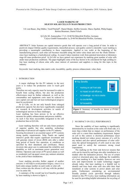
A summary of the overall top level benefits provided<br />
by laser marking is shown in figure 1.<br />
Figure 1: Summary of benefits as shown at PVSEC<br />
poster session<br />
2 NO IMPACT ON CELL PER<strong>FOR</strong>MANCE<br />
Since the usability of laser marking is significantly<br />
determined by its location at the solar cells front side, it is<br />
more than evident that no impact on performance of the<br />
solar cell is a more than mandatory requirement. Impact<br />
on cell in this context is electrical performance (laser<br />
marking should not reduce power outcome of a cell by<br />
any means) and also optical performance of solar cellssince<br />
the optical homogeneity of cells used in one solar<br />
panel need to satisfy the customers strong visual<br />
expectations.<br />
The marking on the front side however ensures that<br />
cells can be traced by and large also after installation in a<br />
module after the lamination process. The use of certain<br />
coated or structured glass may challenge the readability<br />
of a laser marking in a final module, however our own<br />
tests and improvements in reader technology suggest<br />
already today, that laser marking is a helpful tool to<br />
identify and trace back solar cells also after their final<br />
instalment at solar systems in power plants and solar<br />
parks. Furthermore considering an environmental<br />
friendly product circle (provided through industry<br />
initiatives like PV-Cycle), laser marking information can<br />
be used for providing helpful information for recycling of<br />
Page 1 of 5
Presented at the 25th European PV Solar Energy Conference and Exhibition, 6-10 September 2010, Valencia, Spain<br />
solar panels. Recycling bodies may be grateful for any<br />
hint on materials used some decades later, when solar<br />
products reach their recycling plant, long after they have<br />
been made.<br />
happen if the laser marks are “burned” to deeply into the<br />
silicon wafer, rather then being written in a specified<br />
range of allowed depths at surface level.<br />
Figure 2: Digital Tracing by laser marking along the<br />
full value chain of the solar industry: from raw wafer<br />
till PC-Cycle.<br />
3 WRITING <strong>OF</strong> MARKS<br />
Laser marking starts with the writing of marks, e.g.<br />
the data matrix code. The well defined writing process<br />
actually is the essential step of laser marking.<br />
optimized<br />
non-optimized<br />
Figure 4: Writing Laser marks with different laser<br />
parameter: variation in size, shape and pulse duration<br />
in order to optimize readability.<br />
Therefore one hand parameters such as laser power,<br />
wavelength and duration of writing need to be defined<br />
and confirmed by practical test.<br />
On the other hand, despite preferably rather shallow laser<br />
writing, the marks shall be deep enough, to avoid getting<br />
etched away at the wet-bench processes during solar cell<br />
production.<br />
Best results have been achieved with Nd:YAG –<br />
Laser, operating at wavelength of e.g. 1064 nm with<br />
pulse durations of 20 ~ 50 ns and power of 5 ~ 30 W,<br />
creating dots of 100 µm diameter and 10~30 μm depth –<br />
before etching.<br />
Last not least the shape and depth will have major<br />
impact on the readability. Test like shown in figure 4 did<br />
confirm that without optimized writing process the<br />
readability of laser marking will fall behind requirements<br />
of mass production which are significantly higher than<br />
90%.<br />
Figure 3: Example of an optimized and a non<br />
optimized code, where solar cell fingers are printed<br />
across the data matrix code, whereas the optimized<br />
code fit well between solar cell fingers. See also<br />
Chapter 6 Data-Matrix-Code for more info on code<br />
redundancy.<br />
Writing Code has great impact on readability and<br />
specifying the right placement of the laser marking code<br />
can improve greatly the readability. Quite obvious is the<br />
importance of the placement of the code in respect to the<br />
finger layout, as shown in Figure 3. But moreover also<br />
the active area of operation of the laser writing the code<br />
and the field of view in which the data-matrix reader can<br />
safely detect the code, need to be considered. Best results<br />
have been achieved in placing the code close to the centre<br />
of solar cells considering bus-bar and finger layout.<br />
Great care need to be taken that laser marks are<br />
designed, which do not influence the electrical parameter<br />
of a cell, e.g. create shunts. This failure mode could<br />
Figure 5: Impact on readability through specifying the<br />
right process for WRITING laser marking code.<br />
4 READING <strong>OF</strong> MARKS<br />
As already pointed out in the previous section of<br />
writing the laser marks, it is essential to create optimized<br />
laser marks in order to achieve the highest possible<br />
reading rates.<br />
Page 2 of 5
Presented at the 25th European PV Solar Energy Conference and Exhibition, 6-10 September 2010, Valencia, Spain<br />
Figure 6: Example of an industrial type data-matrixreader<br />
from IOSS GmbH. This reader with adjustable<br />
light and camera parameters in order to optimize<br />
readability was used for results shown in this paper.<br />
In our experiments we covered inspection systems and<br />
light sources of different supplier. As a prime example<br />
this paper is focussing on results achieved with IOSS<br />
data-matrix-reader (DMR), in reference to the<br />
demonstration shown at the exhibition.<br />
Throughout our production line the surface of solar<br />
cells changes as a result of various etching, oxidation or<br />
heating processes. Hence an optimization of reading<br />
equipment had to be undertaken.<br />
While the light source in regular DMR was provided<br />
by blue LED, we found improved reading rate with red<br />
LED, especially after wet bench processes. Further<br />
enhancement was done by optimized shutter speed in<br />
order to regulate the exposure time.<br />
Figures 5 and 7 provide insight on the very vast<br />
variation of readability as a function of write-process<br />
optimization of the laser marks (figure 5) and as a<br />
function of read-process optimization (figure 7).<br />
Figure 7: Impact on readability through specifying the<br />
right process settings for READING laser marking<br />
code.<br />
For best results in industrial mass production process<br />
it is obvious that both measures need to be taken. The<br />
optimization is done through learning in iterative steps<br />
and learning is enhanced with greater volume produced.<br />
Figure 8: Sequence for the checking of change in micro-crack behaviour through laser marking did confirm no difference<br />
compared to the peer group of un-laser-marked wafer.<br />
Page 3 of 5
Presented at the 25th European PV Solar Energy Conference and Exhibition, 6-10 September 2010, Valencia, Spain<br />
5 MECHANICAL STRESS TEST<br />
Another important factor for implementing laser<br />
marking technology into an industrial mass-production<br />
process is the stability of the process during volume<br />
production. But also is the proof that there is no impact<br />
on the product itself. Great care has been taken in<br />
confirming that the new feature will have no impact on<br />
cell handling, will cause no micro cracks or breakage and<br />
has no affect on the yield of production.<br />
Micro crack investigations have been carried out with<br />
wafer stacks from 100 to 300 wafer each stack, for both<br />
manual handling and automated handling. Wafers haven<br />
been carried and shifted around in real mass production<br />
environment simultaneously with their non –laser marked<br />
counterparts as shown in figure 8.<br />
After initial micro-crack investigation, transportation<br />
and handling of wafer took place to apply same stresslevel<br />
as wafer would experience during regular<br />
production. By additional twist test any potentially<br />
available micro crack would see further amplification.<br />
The twist test was carried out with about 70% of the force<br />
of a prior determined breakage force.<br />
Red: no marks Green: flat marks Blue: deep marks<br />
Figure 10: Investigation of solar cells stability: the<br />
force required to create breakage shows no correlation<br />
with laser marking.<br />
6 DATA MATRIX CODE<br />
The chosen code is a 2-dimensional industry standard<br />
data matrix code called DataMatrixECC200. It is a defacto<br />
industry standard with a significant robustness. It<br />
contains about 25% redundancy achieved through a Reed<br />
Solomon Error Correction.<br />
Figure 9: Investigation of solar cells stability: the ballon-ring<br />
test did provide evidence that breakage cracks<br />
have no correlation with the laser marks.<br />
Additional Investigation carried out by the<br />
independent Fraunhofer CSP institute performing the<br />
Ball-On-Ring-Test-Method on 160 μm thick solar cells<br />
samples, with a variation of different depth of the marks.<br />
The cracks do evidently not have their root cause in any<br />
laser mark, and ongoing cracks are running rather in<br />
between the individual marks than across them. This<br />
confirmed that there is no significant influence on<br />
breakage strength in the vicinity of the laser marks.<br />
Figure 10 shows the distribution of the force required to<br />
create breakage of a solar cell, in relation to the depth of<br />
the laser marks.<br />
correctable<br />
non correctable<br />
Figure 11: Top picture shows how the data is<br />
distributed across the data-matrix for best data<br />
reliability and recovery. The lower two pictures are<br />
examples of correctable and non-correctable code.<br />
In a 14x14 data matrix code there are 12x12 dots left<br />
over for data. The outer lines of the code are required for<br />
better code identification by the reader. The real data are<br />
Page 4 of 5
Presented at the 25th European PV Solar Energy Conference and Exhibition, 6-10 September 2010, Valencia, Spain<br />
scrambled and strategically distributed over the whole<br />
area in order to reach highest robustness against missing<br />
dots, disturbance or corruption of the code as shown in<br />
Figure 11.<br />
Especially for purposes in the solar industry (for example<br />
the occasional possibility that solar cell fingers could be<br />
printed over the code) the capability and structure of error<br />
correction is of importance.<br />
ACKNOWLEDGMENTS<br />
We gratefully acknowledge fruitful discussions and<br />
contributions by equipment provider, external institutes<br />
namely Fraunhofer and last but not least customers<br />
supporting our development.<br />
REFERENCES<br />
[1] Patent: WO/2007/099138 Solar cell marking method,<br />
and solar cell, Jörg Müller et al.<br />
[2] Fraunhofer CSP “Strength Characterization of Laser<br />
Marked Solar <strong>Cells</strong>“, V 63/2008 – “Strength<br />
Characterization of Laser Marked Solar <strong>Cells</strong>”<br />
[3] ASTM 1239-95 “Reporting Uniaxial Strength Data<br />
and Estimating Weibull Distribution Parameters for<br />
Advanced Ceramics”, 1995<br />
[4] IOSS GmbH, H.Richter, J Gässler, Information<br />
about Data Matrix Code (2010)<br />
[5] St. Geissler, G Simons, Microcrack-Investigations<br />
(2008).<br />
Figure 12: readability of a data-matrix code.<br />
Figure 12 shows a real-life photo from the chosen<br />
IOSS reader and its analysing software, where rot dots<br />
indicating the readability status of the code on the screen<br />
Since the code is available in various sizes, e.g. 14x14,<br />
12x26 or 8x32 it need to be chosen in consideration of<br />
various parameter including finger pitch of a solar cell,<br />
capability to store different amount of data or the time<br />
required to write the code, as well as possible space<br />
constrains. Q-<strong>Cells</strong> did experiments to optimize code size<br />
and placement on the solar cell surface for better massproduction<br />
results.<br />
An example of an actual implementation of a laser<br />
marking ID Code is given in figure 13. The encoded<br />
information can contain information such as: producer<br />
identifier, check digit, year/ week, marker & running<br />
number.<br />
Figure 13: example of data-matrix code content<br />
Page 5 of 5