The Mathematics of Beam Deflection
The Mathematics of Beam Deflection
The Mathematics of Beam Deflection

You also want an ePaper? Increase the reach of your titles
YUMPU automatically turns print PDFs into web optimized ePapers that Google loves.
<strong>The</strong> <strong>Mathematics</strong> <strong>of</strong> <strong>Beam</strong> <strong>Deflection</strong><br />
Scenario<br />
As a structural engineer you are part <strong>of</strong> a team working on the design <strong>of</strong> a prestigious new hotel complex in a<br />
developing city in the Middle East. It has been decided that the building will be constructed using structural<br />
steelwork and, as the design engineer, you will carry out the complex calculations that will ensure that the<br />
architect’s vision for this new development can be translated into a functional, economic and buildable<br />
structure.<br />
As part <strong>of</strong> these calculations you must assess the maximum deflections that will occur in the beams <strong>of</strong> the<br />
structure and ensure that they are not excessive. In this exercise you will apply numerical integration<br />
techniques to solve some typical beam deflection design problems using techniques that form the basis <strong>of</strong><br />
the calculations that would be undertaken in real life albeit <strong>of</strong>ten carried out using sophisticated and powerful<br />
computer analysis s<strong>of</strong>tware.<br />
Importance <strong>of</strong> Exemplar in Real Life<br />
Structures such as buildings and bridges consist <strong>of</strong> a number <strong>of</strong> components such as beams, columns and<br />
foundations all <strong>of</strong> which act together to ensure that the loadings that the structure carries is safely<br />
transmitted to the supporting ground below.<br />
<strong>The</strong>, normally, horizontal beams can be made from steel, timber or reinforced concrete and have a cross<br />
sectional shape that can be rectangular, T or I shape. <strong>The</strong> design <strong>of</strong> such beams can be complex but is<br />
essentially intended to ensure that the beam can safely carry the load it is intended to support. This will<br />
include its own self-weight, the weight <strong>of</strong> the structure it is supporting and what is <strong>of</strong>ten referred to as “live<br />
load” being the weight <strong>of</strong> people and furnishings in buildings or the weight <strong>of</strong> road or rail traffic in bridges.<br />
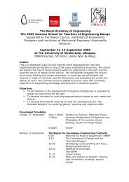
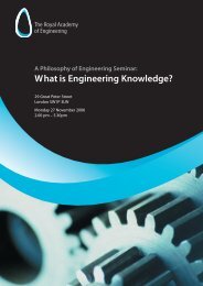
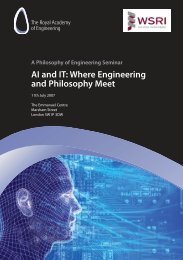
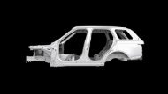
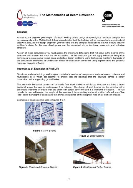
Examples <strong>of</strong> beams can be seen in figures 1 to 4<br />
Figure 1: Steel <strong>Beam</strong>s<br />
Figure 2: Bridge <strong>Beam</strong>s<br />
Figure 3: Reinforced Concrete <strong>Beam</strong>s<br />
Figure 4: Cantilevered Timber <strong>Beam</strong>s<br />
-1-
In addition to the requirements for the beam to safely carry the intended design loads there are other factors<br />
that have to be considered including assessing the likely deflection <strong>of</strong> the beam under load. If beams deflect<br />
excessively then this can cause visual distress to the users <strong>of</strong> the building and can lead to damage <strong>of</strong> parts<br />
<strong>of</strong> the building including brittle partition dividers between rooms and services such as water and heating<br />
pipes and ductwork.<br />
<strong>Beam</strong> design is carried out according to principles set out in Codes <strong>of</strong> Practice and typically the maximum<br />
deflection is limited to the beam’s span length divided by 250. Hence a 5m span beam can deflect as much<br />
as 20mm without adverse effect. Thus, in many situations it is necessary to calculate, using numerical<br />
methods, the actual beam deflection under the anticipated design load and compare this figure with the<br />
allowable value to see if the chosen beam section is adequate.<br />
Background <strong>The</strong>ory<br />
To calculate beam deflections a standard fundamental formula is used to determine deflections base on<br />
beam curvature. This is given by the expression:<br />
Where:<br />
R =<br />
Curvature =<br />
2<br />
1 M d v<br />
= = −<br />
…(1)<br />
R EI<br />
2<br />
dx<br />
<strong>The</strong> radius <strong>of</strong> the shape <strong>of</strong> the curved beam at a distance x from the origin, normally taken at the left<br />
or right hand end <strong>of</strong> the beam<br />
E = <strong>The</strong> Elastic or Young’s modulus <strong>of</strong> the material from which the beam is fabricated. For steel this can<br />
be assumed to be 210 kN/mm 2 .<br />
I = <strong>The</strong> Second Moment <strong>of</strong> Area <strong>of</strong> the beam’s cross-section. This value depends on the shape <strong>of</strong> the<br />
cross section and is normally obtained from tables. Its units are m 4 or mm 4 or cm 4 .<br />
See http://www.rainhamsteel.co.uk/products/universal_beams2nonsfb.html for typical section sizes in<br />
structural steelwork<br />
M = <strong>The</strong> Bending Moment at the section, distance x from the origin<br />
v = <strong>The</strong> vertical deflection at the section distance x from the origin.<br />
In the above formula E and I are normally constant values whilst v, x and M are variables. M can be<br />
expressed in terms <strong>of</strong> distance x and hence double integration techniques can be used to solve the above<br />
expression to calculate the deflection v.<br />
In other words:<br />
or<br />
2<br />
d v<br />
= −<br />
2<br />
dx<br />
v = −<br />
M<br />
EI<br />
M<br />
∫ ∫<br />
dxdx<br />
EI<br />
… (2)<br />
<strong>The</strong> Bending Moment is a means <strong>of</strong> describing mathematically the amount <strong>of</strong> bending and deflection that will<br />
occur in a beam under a given loading system and is defined as the sum <strong>of</strong> the moments <strong>of</strong> all forces to the<br />
left or right <strong>of</strong> the section under consideration. It doesn’t matter whether the left or right is taken as the<br />
answer will be the same in both cases. For example in figure 5 below the simply supported beam shown<br />
carries a uniformly distributed load <strong>of</strong> 10 KN/m. (note the units). When a load is described as uniformly<br />
distributed it means that the load intensity is the same throughout. <strong>The</strong> total load on the span will be 5x10 =<br />
50 kN and hence the supporting reactions as marked on the diagram will each be 25 kN.<br />
x<br />
X<br />
beam<br />
A<br />
Load = 10 kN/m: Total Load = 50 kN<br />
B<br />
column<br />
5m<br />
Reaction = 25kN<br />
Reaction = 25kN<br />
X<br />
Figure5: Loads and Reactions on a simply supported beam<br />
-2-
At X, a distance x from the left hand support the Bending Moment, M, will be given as :<br />
M<br />
x<br />
2<br />
= ( 25 × x)<br />
− (10 × x × ) = 25x<br />
− 5x<br />
… (3)<br />
2<br />
Note that to obtain this expression we have taken moments <strong>of</strong> all forces to the left <strong>of</strong> X and assumed that<br />
clockwise moments are taken as positive.<br />
Hence combining all the above expressions we can say that:<br />
and<br />
2<br />
d v<br />
= −<br />
2<br />
dx<br />
M<br />
EI<br />
25x<br />
− 5x<br />
= −<br />
EI<br />
⎡<br />
3<br />
dv 1<br />
2 1 25 2 x ⎤<br />
∴ = −<br />
∫<br />
(25x<br />
− 5x<br />
) dx = − ⎢ x − 5 + A⎥<br />
dx EI<br />
EI ⎢⎣<br />
2 3 ⎥⎦<br />
⎡<br />
4<br />
1 25 3 x<br />
⎤<br />
v = − ⎢ x − 5 + Ax + B⎥<br />
EI ⎢⎣<br />
6 12<br />
⎥⎦<br />
2<br />
… (4)<br />
… (5)<br />
<strong>The</strong> EI term is taken outside <strong>of</strong> the integration as both E and I are constant values. <strong>The</strong> terms A and B are<br />
constants <strong>of</strong> integration. To solve for the deflection v is necessary to solve for A and B by applying<br />
appropriate boundary conditions which are (a) when x=0 then v= 0 and (b) when x= 5m then v= 0. In other<br />
words because the left and right hand ends are both supports then they can not deflect downwards.<br />
A further boundary condition can be deduced in that at mid-span, by symmetry <strong>of</strong> the beam and loading, the<br />
rotation (or slope <strong>of</strong> the curve) which is the term dv/dx must be zero. i.e when x=L/2 = 2.5m then dv/dx=0.<br />
<strong>The</strong> substitution <strong>of</strong> any two <strong>of</strong> these three boundary conditions will give B=0 and A = 52.08.<br />
Hence:<br />
⎡<br />
4<br />
⎤<br />
⎡<br />
4<br />
1 25 3 x<br />
1 25 3 x<br />
⎤<br />
v = − ⎢ x − 5 + Ax + B⎥<br />
= − ⎢ x − 5 + 52. 08⎥<br />
… (6)<br />
EI ⎢⎣<br />
6 12<br />
⎥⎦<br />
EI ⎢⎣<br />
6 12<br />
⎥⎦<br />
<strong>The</strong> above expression can now be used to calculate the deflection at any point on the beam. In practice it is<br />
the maximum deflection that is <strong>of</strong> interest and common sense would say that for this example this occurs at<br />
mid-span and can be calculated by substituting x=L/2=2.5m into equation 6 above. If it is not obvious<br />
where the maximum deflection occurs this will be where there is a change in slope <strong>of</strong> the beam where<br />
dv/dx=0 . Hence equation (6), or its equivalent in a similar but different problem, could be differentiated and<br />
equated to find the distance x max where the rotation, dv/dx, is zero. Substituting this value for x max into<br />
equation (6) (or its equivalent) will give the maximum deflection, v max.<br />
ooOoo<br />
-3-
Questions<br />
Example Data: For the steel beams given in figures 6 to 9 check for the following data<br />
x<br />
X<br />
x<br />
X<br />
<strong>Beam</strong> built in to<br />
a wall providing<br />
rigid support at one<br />
end only<br />
Load = 15 kN/m: Total Load = 150kN<br />
beam<br />
A<br />
Load = 9.8 kN/m: Total Load = 34.3 kN<br />
beam<br />
B<br />
A<br />
10m<br />
B<br />
3.5m<br />
X<br />
Figure 6: Simply Supported <strong>Beam</strong><br />
X<br />
x<br />
X<br />
Figure 7: Cantilevered <strong>Beam</strong><br />
<strong>Beam</strong> built in to<br />
a wall providing<br />
X<br />
rigid support at one<br />
end only<br />
x<br />
column<br />
A<br />
Total Load = 75kN<br />
beam<br />
10m<br />
B<br />
15 kN/m<br />
A<br />
Total Load = 35kN<br />
beam<br />
3.5m<br />
B<br />
20 kN/m<br />
X<br />
Figure 8: Simply Supported <strong>Beam</strong> - Tapered Load<br />
X<br />
Figure 9: Cantilevered <strong>Beam</strong> - Tapered Load<br />
Figure E<br />
I L Load<br />
Calculate deflections at:<br />
(kN/mm 2 ) (cm 4 ) (m) (kN/m)<br />
6 210 45,730 10.0 15.0 Mid span <strong>of</strong> beam<br />
7 210 33,300 3.5 9.8 End <strong>of</strong> cantilever<br />
8 210 45,730 10.0 Zero to 15 (see figure 8) Mid span <strong>of</strong> beam<br />
9 210 37,050 3.5 Zero to 20 (see figure 9) End <strong>of</strong> cantilever<br />
-4-
Note that two <strong>of</strong> the problems are based on cantilever beams where the beam is held rigidly at one end and<br />
is unsupported at the other end. <strong>The</strong> boundary conditions in this case are that at the built-in end both<br />
rotation and deflection will be zero. In all cases, when calculating the equation <strong>of</strong> Bending Moment, M, take<br />
moments <strong>of</strong> all forces to the left <strong>of</strong> the section X-X a shown in the figures.<br />
Where to find more<br />
1. Ray Hulse & Jack Cain, Structural Mechanics, 2 nd edn, Palgrave, 2000. (ISBN 0-333-80457-0)<br />
2. John Bird, Engineering <strong>Mathematics</strong>, 5 th edn, John Bird, 2007 (ISBN 978-07506-8555-9)<br />
ooOoo<br />
-5-
<strong>The</strong> <strong>Mathematics</strong> <strong>of</strong> <strong>Beam</strong> <strong>Deflection</strong><br />
INFORMATION FOR TEACHERS<br />
Teachers will need to understand and explain the theory outlined above and have knowledge <strong>of</strong>:<br />
Some terminology relating to structural design and construction<br />
Integration techniques<br />
Geometry <strong>of</strong> the triangle including area and centroid position<br />
Topics covered from <strong>Mathematics</strong> for Engineers<br />
Topic 1 Mathematical Models in Engineering<br />
Topic 7 Integration<br />
Learning Outcomes<br />
LO 01: understand the idea <strong>of</strong> mathematical modelling<br />
LO 07: know how to use integration<br />
LO 11: construct rigorous mathematical arguments and pro<strong>of</strong>s<br />
LO 12: comprehend translations <strong>of</strong> common realistic contexts into mathematics<br />
LO 13: use ICT effectively<br />
Assessment Criteria<br />
AC 1.1: state assumptions made in establishing a mathematical model<br />
AC 1.2: describe and use the modelling cycle<br />
AC 7.1: find definite and indefinite integrals <strong>of</strong> functions<br />
AC 7.2: use integration to find areas and volumes<br />
AC 7.4: find centroid <strong>of</strong> a plane<br />
AC 11.1: use precise statements, logical deduction and inference<br />
AC 11.2: manipulate mathematical expressions<br />
AC 11.3: construct extended arguments to handle substantial problems<br />
AC 12.1: read critically and comprehend longer mathematical arguments or examples <strong>of</strong> applications.<br />
AC 13.1: use calculator technology and other permitted resources (such as formulae booklets or<br />
statistical tables) accurately and efficiently<br />
AC 13.2: understand when not to use such technology, and its limitations<br />
AC 13.3: give answers to appropriate accuracy<br />
Links to other units <strong>of</strong> the Advanced Diploma in Construction & <strong>The</strong> Built Environment<br />
Unit 3<br />
Unit 29<br />
Unit 30<br />
Unit 31<br />
Civil Engineering Construction<br />
Science and materials in construction and the Built Environment<br />
Structural Mechanics<br />
Design<br />
Solution to the Questions<br />
Figure Answer<br />
<strong>Deflection</strong> (mm)<br />
6 20.34<br />
7 2.63<br />
8 10.16<br />
9 1.29<br />
ooOoo<br />
-6-