AT-GS950/xxPS PoE Series Installation Guide Rev B - Allied Telesis
AT-GS950/xxPS PoE Series Installation Guide Rev B - Allied Telesis
AT-GS950/xxPS PoE Series Installation Guide Rev B - Allied Telesis

Create successful ePaper yourself
Turn your PDF publications into a flip-book with our unique Google optimized e-Paper software.
<strong>AT</strong>-<strong>GS950</strong>/10PS, <strong>AT</strong>-<strong>GS950</strong>/16PS, and <strong>AT</strong>-<strong>GS950</strong>/48PS Switches <strong>Installation</strong> <strong>Guide</strong><br />
Speed (SPD)<br />
and<br />
Link/Activity (L/A)<br />
LEDs<br />
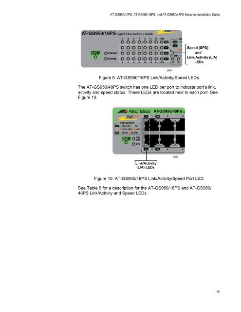
Figure 9. <strong>AT</strong>-<strong>GS950</strong>/16PS Link/Activity/Speed LEDs<br />
The <strong>AT</strong>-<strong>GS950</strong>/48PS switch has one LED per port to indicate port’s link,<br />
activity and speed status. These LEDs are located next to each port. See<br />
Figure 10.<br />
Link/Activity<br />
(L/A) LEDs<br />
Figure 10. <strong>AT</strong>-<strong>GS950</strong>/48PS Link/Activity/Speed Port LED<br />
See Table 6 for a description for the <strong>AT</strong>-<strong>GS950</strong>/16PS and <strong>AT</strong>-<strong>GS950</strong>/<br />
48PS Link/Activity and Speed LEDs.<br />
19

![AT-8100L/8POE-E [Rev B] - Allied Telesis](https://img.yumpu.com/25714603/1/190x245/at-8100l-8poe-e-rev-b-allied-telesis.jpg?quality=85)