WDW Product Brochure - Evapco
WDW Product Brochure - Evapco
WDW Product Brochure - Evapco

You also want an ePaper? Increase the reach of your titles
YUMPU automatically turns print PDFs into web optimized ePapers that Google loves.
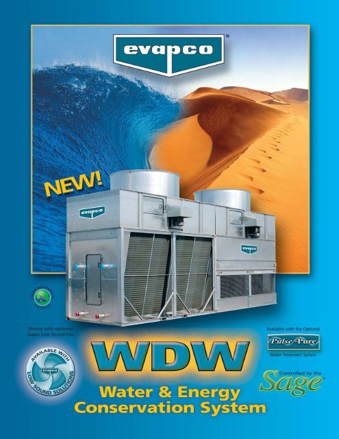
Shown with optional<br />
Super Low Sound Fan<br />
Available with the Optional<br />
Water Treatment System<br />
Controlled by the
®<br />
Joining the Best of Two Worlds to<br />
The New <strong>WDW</strong> water and energy<br />
conservation system has been specifically<br />
designed to optimize both the<br />
evaporative (latent) and dry (sensible)<br />
modes of cooling. The <strong>WDW</strong> saves water<br />
and conserves energy by joining an evaporative<br />
and dry cooler into one unit.<br />
The dry cooling section of the <strong>WDW</strong> closed<br />
circuit cooler utilizes a copper coil with aluminum<br />
fins to maximize the surface area<br />
available for heat transfer. No evaporation<br />
takes place in the dry cooling section. In the<br />
all dry mode of operation no water is consumed<br />
and no plume is created.<br />
The evaporative cooling section utilizes the<br />
proven energy efficient, Thermal-Pak ® coil<br />
technology and the easy maintenance features<br />
of EVAPCO’s ATW induced draft Closed<br />
Circuit Cooler line. Evaporative cooling provides<br />
lower system operating temperatures<br />
and higher overall system efficiencies.<br />
At peak ambient temperatures when both<br />
wet and dry sections are in operation, a<br />
portion of the heat load is rejected through<br />
dry cooling. This decreases water consumption<br />
and offers additional cost savings<br />
through reduced water make-up, blowdown,<br />
and chemical consumption.<br />
The <strong>WDW</strong> closed circuit cooler is also available<br />
with EVAPCO’s Super Low Sound Fan<br />
which provides the lowest sound levels in<br />
the industry on induced-draft products while<br />
consuming 50% less energy than comparable<br />
centrifugal fan units.<br />
The<br />
Super Low Sound Technology<br />
The Super Low Sound Fan is optional on the <strong>WDW</strong> and<br />
provides up to a 15 dB(A) sound level reduction compared<br />
to standard dry or evaporative coolers.<br />
• Extreme Wide Chord Blade Design with<br />
forward swept blade.<br />
• One-piece molded heavy duty FRP<br />
construction.<br />
• High efficiency axial propeller design.<br />
Water and Energy Conservation<br />
Control System<br />
The only way to properly control and<br />
operate the <strong>WDW</strong> Water and Energy<br />
Conservation System is to provide as<br />
standard, the Sage Water and Energy<br />
Conservation Control System.<br />
The Sage is designed to optimally control<br />
the fan motors in both the wet and<br />
dry sections, and the pump motor in the<br />
wet section of the <strong>WDW</strong>. The Sage will<br />
efficiently reject the building load using<br />
the minimal amount of water and energy.<br />
• Sophisticated control system that<br />
measures & analyses water inlet & outlet<br />
temperatures and the ambient dry<br />
bulb to minimize water consumption<br />
• Single variable frequency drive controls<br />
both fan motors<br />
• Maximizes water savings<br />
<br />
2<br />
The <strong>WDW</strong> is the ideal solution for:<br />
Reducing Water Consumption<br />
Lower Energy Costs<br />
Visible Plume Reduction<br />
Super low sound levels<br />
©2007 EVAPCO, INC.<br />
The Sage features:<br />
• A NEMA 3R panel, painted steel design and<br />
Main Disconnect<br />
• A programmable logic control and operator<br />
interface on the panel door<br />
• UL and cUL Approval.<br />
• DC power supply for the PLC and<br />
instrumentation.<br />
• The Sage is standard with one variable<br />
frequency drive and two motor starters to<br />
control both fans independently, as well as<br />
a motor starter for the pump.<br />
• Optional MODBUS RS485 communication<br />
ports for the Building Automation System.
Save Water and Reduce Energy Consumption!<br />
WATER & ENERGY CONSERVATION SYSTEM<br />
The <strong>WDW</strong> product line of closed circuit coolers reflects EVAPCO’s commitment to energy conservation and<br />
environmentally friendly designs.<br />
The <strong>WDW</strong> optimizes latent and sensible heat transfer to save system water. This is accomplished by joining<br />
a dry cooling section with EVAPCO’s proven induced-draft closed circuit evaporative cooler.<br />
The <strong>WDW</strong> offers an energy efficient solution for those applications where water savings are vital.<br />
The <strong>WDW</strong> is the industry's first closed circuit cooler available with non-chemical water treatment, water<br />
conservation and low sound emissions.<br />
Zero Maintenance Water<br />
Distribution System with<br />
ZM Spray Nozzle<br />
The <strong>WDW</strong> closed circuit cooler utilizes the<br />
ZM Spray Nozzle in the evaporative section<br />
of the cooler. The Zero Maintenance water<br />
distribution system design allows the largest<br />
debris to flow easily through the nozzle and<br />
eliminates the need for nozzle and water<br />
distribution system maintenance.<br />
Optional Pulse~Pure Water Treatment System<br />
Dedicated Dry Cooling Coil<br />
The dry cooling coil on the <strong>WDW</strong> is<br />
used exclusively for the purpose of<br />
dry cooling. The copper coils are<br />
equipped with aluminum fins and<br />
are arranged in a “V” configuration<br />
to maximize surface area for heat<br />
transfer. Spray water is isolated<br />
from the finned coils, eliminating<br />
the possibility of scale or biological<br />
material fouling the heat transfer<br />
surface of the dry cooling coils.<br />
The <strong>WDW</strong> is available with <strong>Evapco</strong>'s NEW optional Pulse~Pure <br />
non-chemical water treatment system. The Pulse~Pure Water<br />
Treatment System utilizes pulsed-power technology to provide<br />
CHEMICAL FREE Water Treatment. <strong>Evapco</strong>'s Pulse~Pure system<br />
is an environmentally sensitive alternative for treating water<br />
in evaporative cooled equipment. It does not release harmful byproducts<br />
to the environment and eliminates chemicals completely<br />
from cooler drift and blowdown. The Pulse~Pure system<br />
delivers short, high-frequency bursts of low energy electromagnetic<br />
fields to the recirculating water and will:<br />
• Control Bacteria to Levels Below Traditional Chemical<br />
Water Treatment.<br />
• Control the Formation of Mineral Scale.<br />
• Save Water by Operating at Higher Cycles of Concentration.<br />
• Yield Corrosion Rates Equivalent to Chemical<br />
Water Treatment.<br />
3
®<br />
P RINCIPLE OF O PERATION<br />
<strong>WDW</strong> Principle of Operation<br />
The <strong>WDW</strong> Closed Circuit Cooler rejects heat from the warm process fluid to the atmosphere using a combination of evaporative<br />
(latent) and dry (sensible) cooling modes. Depending on ambient conditions, the heat load may be rejected using pure dry cooling,<br />
evaporative cooling only or a combination thereof. In all modes of operation, the fluid circulates through the dry and evaporative<br />
coil sections in series –eliminating the need for complicated piping and expensive flow-control devices.<br />
Dry-Only Operation-Sensible Heat<br />
Transfer<br />
In the dry mode, the process fluid enters the <strong>WDW</strong> cooler<br />
through the bottom coil connection and circulates through<br />
the finned dry coil section (Fan On). Heat from the process<br />
fluid is dissipated to the atmosphere by sensible heat transfer<br />
through the tube walls to the air passing over the coils. The<br />
finned coils are configured in a V-arrangement to promote<br />
optimal airflow over the coil and to maximize heat transfer<br />
area within the dry section. Air is drawn over the finned coil<br />
by the fan drive system. The process fluid is then circulated<br />
through the evaporative section (Fan Off, Pump Off) and<br />
returns to the heat source via the top coil connection. If additional<br />
capacity is required in this mode, the fan system in the<br />
evaporative section may be operated to move air over the<br />
prime surface coil. This mode of operation eliminates water<br />
consumption when the dry bulb temperature is favorable.<br />
Wet-Only Operation-Latent Heat<br />
Transfer<br />
In the evaporative mode, the process fluid enters the <strong>WDW</strong><br />
cooler through the bottom coil connection and circulates<br />
through the finned coil section (Fan off). The fluid then enters<br />
the evaporative section of the cooler where heat from the<br />
process fluid is transferred through the coil tubes to the water<br />
cascading downward over the coils while simultaneously air is<br />
drawn upward over the coil opposite the water flow using the<br />
fan drive system (Fan On, Pump On). A small portion of the<br />
water is evaporated to dissipate the heat to the atmosphere in<br />
a latent heat transfer. This mode of operation provides fan<br />
energy savings and lower leaving water temperatures by utilizing<br />
evaporative cooling.<br />
Wet and Dry Operation-Evaporative and<br />
Sensible Heat Transfer<br />
The joint wet and dry operation mode provides water savings as<br />
well as low approach temperatures. In this joint mode of operation,<br />
the process fluid enters the <strong>WDW</strong> finned coil section<br />
through the bottom coil connection and rejects a portion of the<br />
heat load to the atmosphere through the tube walls to the air<br />
passing over the coils using sensible heat transfer. The fluid then<br />
enters the evaporative section of the closed circuit cooler where<br />
heat from the process fluid is transferred through the coil tubes<br />
to the water cascading downward over the coils (Pump On,<br />
Both Fans on). Air is drawn through the finned coil and evaporative<br />
coil sections. The cooled fluid then returns to the process<br />
via the upper coil connection.<br />
4
®<br />
D ESIGN A DVANTAGES<br />
Operating Benefits<br />
Heat transfer equipment must always be sized to reject<br />
the full heat load at the highest ambient temperatures.<br />
However, these conditions represent only a fraction of the<br />
cooling season. Since the summer peak ambient wet bulb<br />
is significantly lower than dry bulb for most climates, the<br />
use of evaporative cooling equipment is attractive with<br />
respect to overall unit size and energy consumption.<br />
Evaporative cooling also lends itself to lower system operating<br />
temperatures and higher overall system efficiencies.<br />
The <strong>WDW</strong> maintains all of the advantages of evaporative<br />
cooling while allowing the heat load to be rejected<br />
through dry cooling when ambient conditions are favorable.<br />
In this mode of operation, no water is consumed. An<br />
additional advantage of the unique design of the <strong>WDW</strong> is<br />
that even at high ambient temperatures, a portion of the<br />
heat load is rejected through dry cooling. This decreases<br />
water consumption and offers operational cost savings<br />
through reduced water make-up, blow-down, and chemical<br />
consumption. The <strong>WDW</strong> offers an ideal solution for<br />
applications where minimizing water and energy consumption<br />
is critical. Additionally, the <strong>WDW</strong> offers unique<br />
advantages in freezing climates and for very high-temperature<br />
industrial cooling applications where pure evaporative<br />
cooling is not always feasible.<br />
<strong>WDW</strong> Operational Cost Savings:<br />
Considering an industrial process cooling application for<br />
Minneapolis, MN where the unit is required to reject a<br />
constant heat load of 133 tons and 400 gpm of water circulates<br />
with an entering temperature of 100°F and a leaving<br />
temperature of 90°F. The process operates 24 hours a<br />
day 7 days a week<br />
<strong>WDW</strong> 72-3H-72-3I ATW 77-3I<br />
Wet/Dry Cooler Evaporative Cooler<br />
Total Fan Motor 17.5 10<br />
Size (HP):<br />
Spray Pump 2 2<br />
Size (HP):<br />
The <strong>WDW</strong> requires slightly more fan energy, and therefore<br />
has slightly higher annual fan energy consumption.<br />
However, the <strong>WDW</strong> operates dry for the majority of the<br />
year resulting in reduced spray pump energy consumption.<br />
Overall, the <strong>WDW</strong> provides a cost savings over the conventional<br />
evaporative cooler as shown in the following table:<br />
Energy Costs Comparison<br />
<strong>WDW</strong> 72-3H-72-3I ATW 77-3I<br />
Wet/Dry Cooler Evaporative Cooler<br />
Annual Fan Energy 49,212 36,617<br />
Usage (kWh):<br />
Annual Spray Pump 4,047 13,758<br />
Energy Usage (kWh):<br />
* Annual Energy Cost $3,355 $3,174<br />
(@ $0.063 / kWh):<br />
The <strong>WDW</strong>’s minimal use of water leads to the most significant<br />
savings which exceed the energy savings. The <strong>WDW</strong>’s low water<br />
consumption reduces costs associated with water, sewage, and<br />
chemical treatment. These savings are illustrated below:<br />
WATER VOLUME (K/gallons) Average Monthly Temp.<br />
<strong>WDW</strong> 72-3H-72-3I ATW 77-3I<br />
Wet/Dry Cooler Evaporative Cooler<br />
Total Annual 218 1303<br />
Evaporation (kGallons):<br />
Total Annual * 218 1303<br />
Bleed (kGallons):<br />
Total Annual $1,988 $11,883<br />
Water Cost,<br />
Including Sewage<br />
(@$4.56/kGallon):<br />
Sumarizing these costs, the <strong>WDW</strong> will save the operator over<br />
$8,200 per year!<br />
80<br />
70<br />
60<br />
50<br />
40<br />
30<br />
20<br />
10<br />
0<br />
300<br />
250<br />
200<br />
150<br />
100<br />
50<br />
0<br />
JAN<br />
DRY BULB<br />
WET BULB<br />
<strong>WDW</strong><br />
EVAPORATIVE COOLER<br />
FEB<br />
Water and Sewage Costs Comparison<br />
* Based on 2 cycles of concentration<br />
Annual Operating Costs Comparison<br />
<strong>WDW</strong> 72-3H-72-3I ATW 77-3I<br />
Wet/Dry Cooler Evaporative Cooler<br />
Annual $3,355 $1,659<br />
Energy Cost<br />
(@ 0.063 / kWh):<br />
Total Annual $1,988 $11,883<br />
Water Cost,<br />
Including Sewage:<br />
Total Operating $5,343 $13,542<br />
Costs:<br />
Monthly Water Consumption of the <strong>WDW</strong> Versus a<br />
Conventional Evaporative Cooler (from example above)<br />
MAR<br />
APR<br />
MAY<br />
JUN<br />
JUL<br />
AUG<br />
SEP<br />
OCT<br />
NOV<br />
DEC<br />
* Power Cost 2006 Estimated<br />
5
®<br />
D ESIGN A DVANTAGES<br />
Dedicated Dry Cooling Coil<br />
The dry cooling coil on the <strong>WDW</strong> is used exclusively for the purpose<br />
of dry cooling. The copper coils are equipped with aluminum<br />
fins and are arranged in a "V" configuration to maximize<br />
surface area for heat transfer. Spray water is isolated from<br />
the finned coils, eliminating the possibility of scale or biological<br />
material fouling the heat transfer surface of the dry cooling<br />
coil. Isolating the dry cooling coil also reduces the likelihood of<br />
corrosion compared to designs where the finned coil is wet.<br />
Thermal-Pak ® Evaporative Coil<br />
U.S. Patent No. 4,500,330<br />
EVAPCO's Thermal-Pak ® coils feature a patented design which<br />
assures maximum cooling capacity. The airflow through the<br />
coil is counterflow to the fluid flow, providing the most efficient<br />
heat transfer process. A special coil design is utilized to<br />
reduce the air pressure drop through the unit while maximizing<br />
tube surface area and increasing its heat transfer capabilities.<br />
The uniquely shaped tubes of the coil are staggered in<br />
the direction of airflow to obtain a high film coefficient.<br />
The coils are manufactured from high quality steel tubing following<br />
the most stringent quality control procedures. Each<br />
circuit is inspected to assure the material quality and then<br />
tested before being assembled into a coil. Finally, the assembled<br />
coil is pneumatically tested at 400 psig under water to<br />
ensure it is leak free.<br />
To protect the coil against corrosion, it is placed in a heavy steel<br />
frame and then the entire assembly is dipped in molten zinc<br />
(hot-dip galvanized) at a temperature of approximately 800°F.<br />
Water Sight Tight Air Inlet Louver*<br />
<strong>Evapco</strong>'s innovative air inlet louvers are both water and sight<br />
tight to ensure that the water stays in and the sunlight stays<br />
out of the cold water basin. Using extensive computational<br />
fluid dynamics modeling, <strong>Evapco</strong> engineers developed a louver<br />
to improve “splash resistance” while maximizing airflow. The<br />
resulting design maximizes thermal performance while minimizing<br />
water loss. This sight tight design also inhibits algae<br />
growth more effectively than previous designs.<br />
<strong>Evapco</strong>’s louver design solves the problem of the circulating<br />
water and heat transfer surfaces being directly exposed to<br />
external contaminants and the harsh surroundings.<br />
Water Saving Drift Eliminators<br />
The <strong>WDW</strong> is provided with an efficient drift eliminator system<br />
that effectively reduces entrained water droplets from the air<br />
discharge to less than 0.001% of the spray water flow rate.<br />
The eliminators are constructed of non-corrosive PVC with a<br />
multi-pass design for maximum drift reduction. They are<br />
assembled in modular sections for easy removal and access to<br />
the water distribution system.<br />
In addition to reducing drift, the eliminators also function as<br />
effective debris screens which protects the spray system from<br />
sunlight and debris.<br />
*U.S. Patent #6,923,250<br />
6
®<br />
D ESIGN A DVANTAGES<br />
The Advanced Technology Easy Maintenance Design<br />
Proper preventative maintenance is critical to ensure the longevity and performance of a closed circuit cooler. <strong>Evapco</strong> designs<br />
all of its products for easy maintenance access.<br />
Easy Belt and Motor Access<br />
The fan motor and drive assembly are designed for easy<br />
service and adjustment from the unit’s exterior. The Totally<br />
Enclosed fan motor is mounted external to the unit with a<br />
protective cover which swings aside for maintenance. A<br />
large access door adjacent to the fan motor swings open<br />
enabling easy access to the fan drive system. The belt tension<br />
can be checked and adjusted easily from the outside of the<br />
unit. The fan shaft bearings also have their lubrication lines<br />
extended to the access door for added convenience.<br />
Clean Pan Basin Design<br />
The <strong>WDW</strong> features a completely sloped basin from the upper<br />
to lower pan section. This "Clean Pan" design allows the<br />
water to be completely drained from the basin. The pan<br />
water will drain from the upper section to the depressed<br />
lower pan section where the dirt and debris can be easily<br />
flushed from the drain. Due to dry operation from Fall until<br />
Spring, the "Clean Pan" design allows the end-user to drain<br />
and clean the sump in the Fall to prepare the unit for winter<br />
operation without water in the sump. In this case sump<br />
heaters can be omitted. This design helps prevent buildup of<br />
sedimentary deposits, biological films and minimizes standing<br />
water.<br />
Oversized Access Door<br />
in Dry Cooling Section<br />
The walk-in access door on the <strong>WDW</strong> provides easy access to<br />
the finned coils and internal piping. An internal walkway is<br />
provided as standard to provide a safe working platform.<br />
Zero Maintenance<br />
Water Distribution System<br />
The water distribution system is enclosed and completely protected<br />
by the casing and eliminator panels.<br />
The water distribution system is made from non-corrosive<br />
PVC pipe and features the Zero Maintenance (ZM) spray nozzle.<br />
The ZM nozzle is constructed of heavy duty nylon for corrosion<br />
resistance and long operating life. Zero maintenance is<br />
made possible with large 1-5/16” diameter openings and a<br />
clearance of 1-1/2” between the nozzle opening and water<br />
diverter plate. This allows the largest debris to flow easily<br />
through the ZM spray nozzle.<br />
<strong>Evapco</strong>’s design avoids the problems of biological growth and<br />
fouling that can occur to a water distribution system that is<br />
open with direct exposure to the surroundings.<br />
7
H<br />
®<br />
E NGINEERING D ATA & DIMENSIONS<br />
M<br />
M<br />
Access<br />
Door<br />
W<br />
END ELEVATION<br />
L<br />
SIDE ELEVATION<br />
PUMP END ELEVATION<br />
Spray<br />
Heaviest<br />
“W” “L” “H” Wet Dry Spray Pump Shipping Section Operating Coil<br />
Width Length Height Fan* Fan* Pump Flow Weight Weight † Weight Volume<br />
Model Number** feet/inches feet/inches feet/inches HP HP HP GPM lbs. lbs. lbs. gal.<br />
<strong>WDW</strong> 72-3H-72-3H 7’10” 17’11” 12’10” 7.5 7.5 2 410 14365 6450 18595 246<br />
<strong>WDW</strong> 72-3I-72-3I 7’10” 17’11” 12’10” 10 10 2 410 14450 6480 18660 246<br />
<strong>WDW</strong> 72-4H-72-3H 7’10” 17’11” 12’10” 7.5 7.5 2 410 15335 7630 19985 296<br />
<strong>WDW</strong> 72-4I-72-3I 7’10” 17’11” 12’10” 10 10 2 410 15400 7660 20050 296<br />
<strong>WDW</strong> 72-4J-72-3J 7’10” 17’11” 12’10” 15 15 2 410 15465 7660 20115 296<br />
<strong>WDW</strong> 72-5H-72-3H 7’10” 17’11” 12’10” 7.5 7.5 2 410 16400 8895 21485 348<br />
<strong>WDW</strong> 72-5I-72-3I 7’10” 17’11” 12’10” 10 10 2 410 16470 8930 21550 348<br />
<strong>WDW</strong> 72-5J-72-3J 7’10” 17’11” 12’10” 15 15 2 410 16610 9005 21695 348<br />
<strong>WDW</strong> 96-3I-96-3I 7’10” 23’11-1/2” 12’10” 10 10 3 550 17870 8015 23735 324<br />
<strong>WDW</strong> 96-3J-96-3J 7’10” 23’11-1/2” 12’10” 15 15 3 550 18000 8090 23865 324<br />
<strong>WDW</strong> 96-4I-96-3I 7’10” 23’11-1/2” 12’10” 10 10 3 550 19215 9610 25640 392<br />
<strong>WDW</strong> 96-4J-96-3J 7’10” 23’11-1/2” 12’10” 15 15 3 550 19345 9690 25770 392<br />
<strong>WDW</strong> 96-4K-96-3J 7’10” 23’11-1/2” 12’10” 20 15 3 550 19390 9735 25815 392<br />
<strong>WDW</strong> 96-5I-96-3I 7’10” 23’11-1/2” 12’10” 10 10 3 550 20570 11200 27580 462<br />
<strong>WDW</strong> 96-5J-96-3J 7’10” 23’11-1/2” 12’10” 15 15 3 550 20700 11275 27710 462<br />
<strong>WDW</strong> 112-3J-112-3J 7’10” 27’11-1/2” 12’10” 15 15 3 600 19985 9170 26810 380<br />
<strong>WDW</strong> 112-3K-112-3J 7’10” 27’11-1/2” 12’10” 20 15 3 600 20070 9215 26850 380<br />
<strong>WDW</strong> 112-4J-112-3J 7’10” 27’11-1/2” 12’10” 15 15 3 600 21595 11025 29080 460<br />
<strong>WDW</strong> 112-4K-112-3J 7’10” 27’11-1/2” 12’10” 20 15 3 600 21640 11065 29125 460<br />
<strong>WDW</strong> 112-4L-112-3J 7’10” 27’11-1/2” 12’10” 25 15 3 600 21670 11100 29155 460<br />
<strong>WDW</strong> 112-5J-112-3J 7’10” 27’11-1/2” 12’10” 15 15 3 600 23180 12865 31340 540<br />
<strong>WDW</strong> 112-5K-112-3J 7’10” 27’11-1/2” 12’10” 20 15 3 600 23225 12910 31380 540<br />
<strong>WDW</strong> 112-5L-112-3J 7’10” 27’11-1/2” 12’10” 25 15 3 600 23260 12940 31415 540<br />
* Consult factory for airflow data<br />
** Please consult EVAPCO for detailed unit selections and complete product line.<br />
† Heaviest section is evaporative fan/coil section<br />
Unit dimensions may vary slightly from the catalog. See factory certified prints for exact dimensions<br />
Coil connections are beveled for weld (4" inlets, 4" outlets). Other connections types such as male pipe thread, grooved for<br />
mechanical coupling, or flanged are available as options.<br />
8
®<br />
R ECOMMENDED S TEEL S UPPORT<br />
The recommended support for EVAPCO Closed Circuit<br />
Coolers is structural “I” beams located under the outer<br />
flanges and running the entire length of the unit. The unit<br />
should be elevated to allow access underneath the unit<br />
and to the roof below. Mounting holes 3/4” in diameter<br />
are located in the bottom flanges of the pan section to<br />
provide for bolting to the structural steel. (Refer to certified<br />
drawings from the factory for bolt hole locations.)<br />
<strong>WDW</strong> SUPPORTING STEEL DIMENSIONS<br />
A<br />
B<br />
<strong>WDW</strong> 72-72 7’ 10” 17’ 11”<br />
<strong>WDW</strong> 96-96 7’ 10” 23’ 11-1/2”<br />
<strong>WDW</strong> 112-112 7’ 10” 27’ 11-1/2”<br />
Beams should be level before setting the unit in place. Do<br />
not level the unit by shimming between the unit and the<br />
structural steel. Dimensions weights and data are subject<br />
to change without notice. Refer to the factory certified<br />
drawings for exact dimensions.<br />
A<br />
B<br />
A CCESSORIES<br />
Stainless Steel Basin<br />
EVAPCO coolers have a modular design which allows specific<br />
areas to be enhanced for increased corrosion protection.<br />
The basin area of the cooler experiences turbulent mixing of<br />
air and water, in addition to silt build-up. In conjunction<br />
with the EVAPCOAT Corrosion Protection System, EVAPCO<br />
offers an optional Stainless Steel Basin. This option provides<br />
Type 304 stainless steel for the entire basin area including<br />
the support columns of the cooler and the louver frames.<br />
Self Supporting Working Platform<br />
EVAPCO coolers are available with a self-supporting platform<br />
with ladder, which may be easily installed in the field.<br />
This option offers significant savings compared to field constructed<br />
catwalks, which must be supported by a structure<br />
external to the unit. The platform may be installed on either<br />
side, or the end opposite the connections.<br />
Motor Davit<br />
In the event that a fan<br />
motor should need to<br />
be replaced, a motor<br />
davit is available from<br />
which a chain fall can<br />
be mounted to easily<br />
lower the motor to<br />
the ground.<br />
Electric Water Level Control<br />
Closed Circuit Coolers may be ordered with an electric water<br />
level control in lieu of the standard mechanical float and<br />
make-up assembly. This package provides accurate control of<br />
water levels and does not require field adjustment.<br />
Electric Heaters<br />
Electric immersion heaters are available to protect the basin<br />
water from freezing. Basin heaters are sized to maintain<br />
40°F pan water temperature at 0°F ambient with the fans<br />
off. The heater option includes a thermostat and low water<br />
protection device to control the heater and to prevent it<br />
from energizing unless they are completely submerged.<br />
Other Options<br />
• Heater Control Packages<br />
• Vibration Isolators<br />
• Vibration Switches<br />
• Remote Sump Connections<br />
9
®<br />
APPLICATIONS AND WATER QUALITY<br />
Design<br />
<strong>Evapco</strong> units are of heavy-duty construction and designed for<br />
long trouble-free operation. Proper equipment selection,<br />
installation and maintenance is, however, necessary to<br />
ensure full unit performance. Some of the major considerations<br />
in the application of a cooler are presented below. For<br />
additional information, contact the factory.<br />
Air Circulation<br />
The location of a closed circuit cooler is an important consideration<br />
when reviewing system design. Since closed circuit<br />
coolers consume large quantities of air, adequate spacing<br />
around the unit is necessary for it to perform properly. The<br />
best place to locate any closed circuit cooler is on a roof or at<br />
ground level away from walls and other obstructions. Closed<br />
circuit coolers that are located in wells, enclosures, or are<br />
adjacent to high walls must be properly located to avoid the<br />
effects of recirculation. Recirculation occurs when some of<br />
the hot moist discharge air leaving the closed circuit cooler<br />
flows back into the fresh air inlet. When recirculation causes<br />
the inlet wet bulb temperature to the closed circuit cooler to<br />
be increased, the capacity of the closed circuit cooler is<br />
decreased. Refer to EVAPCO Bulletin 311, Equipment Layout<br />
Manual, for the recommended layout guidelines of closed<br />
circuit coolers.<br />
Piping<br />
Cooler piping should be designed and installed in accordance<br />
with generally accepted engineering practices. The piping layout<br />
should be symmetrical on multiple unit systems, and sized<br />
for a reasonably low water velocity and pressure drop.<br />
The standard closed circuit cooler is recommended only on a<br />
closed, pressurized system. The piping system should include<br />
an expansion tank to allow for fluid expansion and purging<br />
air from the system.<br />
Note: Closed Circuit Coolers should never be used on an<br />
open type system. An open type system with a cooler<br />
may result in premature coil failure.<br />
The piping system should be designed to permit complete<br />
drainage of the heat exchanger coil. This will require a vacuum<br />
breaker or air vent to be installed at the high point and a<br />
drain valve installed on both the inlet and outlet connections.<br />
Both must be adequately sized.<br />
All piping should be securely anchored by properly designed<br />
hangers and supports. No external loads should be placed<br />
upon the cooler connections, nor should any of the pipe supports<br />
be anchored to the cooler framework.<br />
Recirculating Water System<br />
Electric pan heaters, steam or hot water coils can be used to<br />
keep the pan water from freezing when the unit cycles off.<br />
Water lines to and from the unit, spray pump and related piping<br />
should be heat traced and insulated up to the overflow<br />
level in order to protect from freezing.<br />
Freeze Protection<br />
If the units are installed in a cold climate and operated yearround,<br />
freeze protection must be provided for the heat<br />
exchanger coils in the unit as well as for the recirculating<br />
water system.<br />
Heat Exchanger Coil<br />
The simplest and most foolproof method of protecting the<br />
heat exchanger coil from freeze-up is to use a glycol solution.<br />
If this is not possible, an auxiliary heat load must be maintained<br />
on the coil at all times so that the water temperature<br />
does not drop below 50°F when the cooler is shut down. Also,<br />
a minimum recommended flow rate of 140 gpm must be<br />
maintained. Consult the factory for heat loss data.<br />
Recirculating Water Quality<br />
It is recommended that <strong>Evapco</strong> or another qualified water<br />
treatment company be contacted to design a water treatment<br />
protocol specifically for equipment and location.<br />
Closed circuit coolers reject heat by evaporating a portion of<br />
the water spray and discharging it as hot, saturated air. As the<br />
spray water evaporates, it leaves behind the mineral content<br />
and impurities of the supply water. If left untreated, these<br />
residuals become concentrated and lead to a buildup of scale,<br />
corrosion, and biological fouling.<br />
Bleed off<br />
To avoid this build-up of residuals, closed circuit coolers are<br />
provided with a bleed valve which allows for a portion of the<br />
spray water to be continually drained from the unit. The<br />
bleed valve, which is located on the pump discharge, should<br />
be set to the "fully open" position so as to ensure a sufficient<br />
bleed rate. Another method to remove residuals is to use a<br />
conductivity controlled blowdown device. This method<br />
should also be considered for water savings. If the bleed is<br />
reduced, the unit should be checked periodically to ensure the<br />
chemistry of the spray water is within the recommended<br />
guidelines as noted in <strong>Evapco</strong>’s Operation and Maintenance<br />
Instructions.<br />
Water Treatment<br />
In some cases the make-up water will have high impurity levels<br />
and a normal bleed will not be enough to prevent scale<br />
formation. In these cases, the services of an experienced water<br />
treatment company should be retained.<br />
The water treatment program prescribed for the given conditions<br />
must be compatible with the unit’s materials of construction,<br />
including the galvanized coil. If an acid is used to<br />
control pH, it should be accurately metered in dilute solution<br />
such that the spray water is held between a pH of 6.5 and 8.3.<br />
Batch feeding of chemicals is not recommended.<br />
Units constructed of galvanized steel operating with circulating<br />
water having a pH of 8.3 or higher may require periodic<br />
passivation to prevent the formation of white rust. White<br />
rust is a corrosion byproduct of the protective zinc barrier and<br />
appears on the metal surface as white, waxy formations. If<br />
white rust forms and is left untreated, it may flake off and<br />
leave the bare metal substrate exposed.<br />
Control of Biological Contaminants<br />
Water quality should be checked regularly for biological contamination.<br />
If biological contamination is detected, a more<br />
aggressive water treatment and mechanical cleaning program<br />
is required. The water treatment program should be<br />
performed in conjunction with a qualified water treatment<br />
company. It is important that all internal surfaces be kept<br />
clean of accumulated dirt or sludge. In addition, the drift<br />
eliminators should be kept in good operating condition to<br />
minimize water from exiting the evaporative cooling unit in<br />
the discharge air.<br />
To minimize the risk of biological contamination, at initial<br />
start up or after an extended shut down, it is recommended<br />
that the cooler be properly treated. Clean all debris such as<br />
leaves and dirt from the unit. Completely fill the basin to the<br />
overflow level with fresh water. Initiate a biocide water treatment<br />
or shock treatment program prior to operating the unit.<br />
It is preferable that all such procedures be conducted or<br />
supervised by a water treatment specialist.<br />
10
®<br />
S PECIFICATIONS<br />
Furnish and install as shown on the plans an EVAPCO Model<br />
_________ induced draft counterflow wet/ dry closed circuit cooler.<br />
Each unit shall have the capacity to cool ________ gpm of _______<br />
from ______ °F to ______ °F with a _____ °F entering wet bulb temperature<br />
with a coil pressure drop not exceeding _____ psi. The unit<br />
shall be capable of operating dry at temperatures at or below<br />
______ °F.<br />
Casing<br />
The casing shall be constructed of G-235 hot-dip galvanized steel<br />
for long life and durability. The casing panels shall totally encase<br />
all sides of the heat transfer surface to protect it from direct exposure<br />
to environmental elements.<br />
Basin<br />
The basin shall be constructed of G-235 hot-dip galvanized steel<br />
for long life and durability. Standard basin accessories on evaporative<br />
cells shall include overflow, drain, type 304 stainless steel<br />
strainers, and brass make-up valve with plastic float. The entire<br />
pan area on evaporative cells shall be enclosed and protected from<br />
exposure to environmental elements. The basin of all evaporative<br />
cells shall be designed with a sloped basin floor.<br />
Heat Transfer Coils:<br />
Coils shall be arranged inside the unit such that all coils will drain<br />
freely when piped together.<br />
All flow control devices necessary to direct the flow of process<br />
fluid between the wet and dry coils shall be provided.<br />
Finned (Dry Cooling) Coils:<br />
Dry cooling coils shall be constructed of seamless copper tubes<br />
with tubular steel headers. To maximize heat transfer, tubes shall<br />
be arranged in a staggered design and be equipped with aluminum<br />
flat plate fins. Fin spacing shall be consistent and optimized<br />
for maximum heat transfer and minimal airside pressure drop.<br />
Prime surface (Evaporative Cooling) Coils:<br />
Cooling coils shall be prime surface steel, encased in a steel framework<br />
with the entire assembly hot-dip galvanized after fabrication.<br />
The coil assembly shall be completely enclosed and protected<br />
from sunlight exposure, environmental elements and debris.<br />
The tubes shall be sloped for free drainage of the coil and<br />
designed for low pressure drop. Units having the heat transfer<br />
coil exposed to direct sunlight and debris shall not be acceptable.<br />
Fan Motor<br />
Total fan motor energy shall not exceed _____ HP. Fan motor(s)<br />
shall be _____ @ _____ HP each for application on _____ volts,<br />
_____ hertz, _____ phase. Fan motor(s) shall be totally enclosed<br />
with a 1.15 service factor, and specifically designed for closed circuit<br />
cooler applications. Motor(s) shall be accessible from the<br />
exterior of the unit. If the fan motors cannot be serviced externally,<br />
the manufacturer must include basin level platforms and<br />
elevated internal platforms for safe access to the drive system.<br />
Drive<br />
Each fan assembly shall be driven by a dedicated fan motor. Each<br />
fan shall be driven by a solid backed V-belt with taper lock<br />
sheaves designed for a 1.5 service factor of the motor nameplate<br />
HP. The belt shall be constructed of neoprene with reinforcing<br />
polyester cords suitable for evaporative cooler service. Belt<br />
adjustment and lubrication of fan shaft bearings shall be accomplished<br />
from the unit’s exterior.<br />
Axial Propeller Fans<br />
Fans shall be wide-chord, axial propeller type of extruded aluminum<br />
alloy construction. The fans shall be installed in a closely fitted<br />
cowl with venturi air inlet for maximum efficiency. Fan screens<br />
shall be galvanized steel mesh and frame, bolted to the fan cowl.<br />
Fan Shaft Bearings<br />
Fan shaft bearings shall be heavy duty self-aligning ball type with<br />
grease fittings extended to the outside of the unit. Bearings shall<br />
be designed for a minimum L-10 life of 75,000 hours.<br />
Water Recirculation Pump<br />
The pump(s) shall be a close-coupled, centrifugal type with<br />
mechanical seal, installed vertically at the factory to allow free<br />
drainage on shut down. The pump motor shall be _____ HP totally<br />
enclosed for outdoor service on _____ volts, _____ hertz, and _____<br />
phase.<br />
Water Distribution System<br />
The water distribution system shall be completely enclosed and<br />
protected from sunlight exposure, environmental elements and<br />
debris. The spray system shall provide a water flow rate over the<br />
evaporative coil of not less than 6 gpm per square foot for maximum<br />
cooling efficiency. The spray header shall be removable for<br />
cleaning, and constructed of schedule 40 polyvinyl chloride pipe<br />
for corrosion resistance. The water shall be distributed over the<br />
entire coil surface by heavy-duty molded nylon ZM spray nozzles<br />
with large 1-5/16” diameter openings and internal sludge ring to<br />
eliminate clogging. ZM Nozzles shall be threaded into spray header;<br />
snap-in nozzles shall not be acceptable.<br />
Eliminators<br />
The unit shall be provided with eliminators made from inert<br />
polyvinyl chloride (PVC). The eliminator design shall incorporate<br />
three changes in air direction to assure complete removal of all<br />
entrained moisture from the discharge air stream. Maximum drift<br />
rate shall be less than 0.001% of the circulating water rate.<br />
Air Inlet Louvers<br />
The air inlet louvers shall be constructed from UV inhibited<br />
polyvinyl chloride (PVC) and incorporate an interlocking design<br />
that allows for easy removal of louvers for access to the entire<br />
basin area for maintenance. The louvers shall have a minimum of<br />
two changes in air direction and be of a non-planar design to prevent<br />
splash-out, block direct sunlight and debris from entering<br />
the basin.<br />
Finish<br />
All basin and casing materials shall be constructed of G-235 heavy<br />
gauge mill hot-dip galvanized steel. During fabrication, all panel<br />
edges shall be coated with a 95% pure zinc-rich compound for<br />
superior protection against corrosion.<br />
Optional Axial Propeller Fans<br />
Units are available with SUPER Low Sound Fans in order to<br />
assure a minimal sound pressure level. Fans shall be high efficiency<br />
axial propeller type with non-corrosive FRP hub and blade<br />
construction. The one-piece molded heavy duty fan construction<br />
shall utilize a forward swept blade design for superior sound<br />
quality. Each fan shall be statically balanced and installed in a<br />
closely fitted cowl with venturi air inlet for maximum fan efficiency.<br />
The fan cowl shall be covered with a heavy gauge hot dip<br />
galvanized steel fan guard.<br />
Sound<br />
The unit shall be designed for low sound with maximum sound<br />
pressure levels not exceeding the following values:<br />
Overall Sound Pressure level dBA<br />
5 feet above fan discharge _________________<br />
Optional Pulse~Pure Non-Chemical<br />
Water Treatment System<br />
Furnish and install a non-chemical water treatment system based<br />
on pulsed-power technology on the re-circulating water system<br />
of each wet/dry closed circuit cooler. System shall be capable of<br />
handling a maximum flow of ______ gpm water.<br />
11
®<br />
<strong>WDW</strong>...Joining the Best of Two Worlds to Save Water<br />
and Reduce Energy Consumption!<br />
World Headquarters/<br />
Research and<br />
Development Center<br />
EVAPCO Facilities<br />
EVAPCO North America<br />
EVAPCO, Inc. — World Headquarters & Research/Development Center<br />
EVAPCO, Inc. P.O. Box 1300 Westminster, MD 21158 USA<br />
PHONE: 410-756-2600 FAX: 410-756-6450 E-MAIL: marketing@evapco.com<br />
EVAPCO, Inc.<br />
North American Headquarters<br />
P.O. Box 1300<br />
Westminster, MD 21158 USA<br />
Phone: 410-756-2600<br />
Fax: 410-756-6450<br />
E-mail: marketing@evapco.com<br />
EVAPCO East<br />
5151 Allendale Lane<br />
Taneytown, MD 21787 USA<br />
Phone: 410-756-2600<br />
Fax: 410-756-6450<br />
E-mail: marketing@evapco.com<br />
EVAPCO Midwest<br />
1723 York Road<br />
Greenup, IL 62428 USA<br />
Phone: 217-923-3431<br />
Fax: 217-923-3300<br />
E-mail: evapcomw@evapcomw.com<br />
EVAPCO West<br />
1900 West Almond Avenue<br />
Madera, CA 93637 USA<br />
Phone: 559-673-2207<br />
Fax: 559-673-2378<br />
E-mail: contact@evapcowest.com<br />
EVAPCO Iowa<br />
925 Quality Drive<br />
Lake View, IA 51450 USA<br />
Phone: 712-657-3223<br />
Fax: 712-657-3226<br />
EVAPCO Iowa<br />
Sales & Engineering<br />
1234 Brady Boulevard<br />
Owatonna, MN 55060 USA<br />
Phone: 507-446-8005<br />
Fax: 507-446-8239<br />
E-mail: evapcomn@evapcomn.com<br />
Refrigeration Valves &<br />
Systems Corporation<br />
A wholly owned subsidiary of EVAPCO, Inc.<br />
1520 Crosswind Dr.<br />
Bryan, TX 77808 USA<br />
Phone: 979-778-0095<br />
Fax: 979-778-0030<br />
E-mail: rvs@rvscorp.com<br />
McCormack Coil Company, Inc.<br />
A wholly owned subsidiary of EVAPCO, Inc.<br />
P.O. Box 1727<br />
6333 S.W. Lakeview Boulevard<br />
Lake Oswego, OR 97035 USA<br />
Phone: 503-639-2137<br />
Fax: 503-639-1800<br />
E-mail: mail@mmccoil.com<br />
EvapTech, Inc.<br />
A wholly owned subsidiary of EVAPCO, Inc.<br />
8331 Nieman Road<br />
Lenexa, KS 66214 USA<br />
Phone: 913-322-5165<br />
Fax: 913-322-5166<br />
E-mail: marketing@evaptechinc.com<br />
Tower Components, Inc.<br />
A wholly owned subsidiary of EVAPCO, Inc.<br />
5960 US HWY 64E<br />
Ramseur, NC 27316<br />
Phone: 336-824-2102<br />
Fax: 336-824-2190<br />
E-mail: mail@towercomponentsinc.com<br />
EVAPCO Europe<br />
EVAPCO Europe, N.V.<br />
European Headquarters<br />
Industrieterrein Oost 4010<br />
3700 Tongeren, Belgium<br />
Phone: (32) 12-395029<br />
Fax: (32) 12-238527<br />
E-mail: evapco.europe@evapco.be<br />
EVAPCO Europe, S.r.l.<br />
Via Ciro Menotti 10<br />
1-20017 Passirana di Rho<br />
Milan, Italy<br />
Phone: (39) 02-939-9041<br />
Fax: (39) 02-935-00840<br />
E-mail: evapcoeurope@evapco.it<br />
EVAPCO Europe, S.r.l.<br />
Via Dosso 2<br />
23020 Piateda Sondrio, Italy<br />
EVAPCO Europe, GmbH<br />
Bovert 22<br />
D-40670 Meerbusch, Germany<br />
Phone: (49) 2159-69560<br />
Fax: (49) 2159-695611<br />
E-mail: info@evapco.de<br />
EVAPCO S.A. (Pty.) Ltd.<br />
A licensed manufacturer of EVAPCO, Inc.<br />
18 Quality Road<br />
Isando 1600<br />
Republic of South Africa<br />
Phone: (27) 11 392-6630<br />
Fax: (27) 11-392-6615<br />
E-mail: evapco@evapco.co.za<br />
Tiba Engineering Industries Co.<br />
A licensed manufacturer of EVAPCO, Inc.<br />
5 Al Nasr Road St.<br />
Nasr City,<br />
Cairo, Egypt<br />
Phone: (20) 2-290-7483/(20) 2-291-3610<br />
Fax: (20) 2-404-4667/ (20) 2-290-0892<br />
E-mail: manzgroup@tedata.net.eg<br />
EVAPCO Asia/Pacific<br />
EVAPCO China<br />
Asia/Pacific Headquarters<br />
1159 Luoning Rd.<br />
Baoshan Industrial Zone<br />
Shanghai, P. R. China,<br />
Postal Code: 200949<br />
Phone: (86) 21-6687-7786<br />
Fax: (86) 21-6687-7008<br />
E-mail: marketing@evapcochina.com<br />
<strong>Evapco</strong> (Shanghai) Refrigeration<br />
Equipment Co., Ltd.<br />
1159 Louning Rd.<br />
Baoshan Industrial Zone<br />
Shanghai, P.R. China<br />
Postal Code: 200949<br />
Phone: (86) 21-6687-7786<br />
Fax: (86) 21-6687-7008<br />
E-mail: marketing@evapcochina.com<br />
Beijing EVAPCO Refrigeration<br />
Equipment Co., Ltd.<br />
Yan Qi Industrial Development District<br />
Huai Rou County<br />
Beijing, P.R. China<br />
Postal Code: 101407<br />
Phone: (86) 10 6166-7238<br />
Fax: (86) 10 6166-7395<br />
E-mail: evapcobj@evapcochina.com<br />
Aqua-Cool Towers (Pty.) Ltd.<br />
A licensed manufacturer of EVAPCO, Inc.<br />
34-42 Melbourne St.<br />
P.O. Box 436<br />
Riverstone, N.S.W. Australia 2765<br />
Phone: (61) 29 627-3322<br />
Fax: (61) 29 627-1715<br />
E-mail: sales@aquacoolingtowers.com.au<br />
EVAPCO...SPECIALISTS IN HEAT TRANSFER PRODUCTS AND SERVICES.<br />
Visit EVAPCO’s Website at: http://www.evapco.com<br />
3M/1007/DGD<br />
Printed on recycled paper using soy-based inks.<br />
Bulletin 240A