eco-ATWB Marketing - Evapco
eco-ATWB Marketing - Evapco
eco-ATWB Marketing - Evapco

You also want an ePaper? Increase the reach of your titles
YUMPU automatically turns print PDFs into web optimized ePapers that Google loves.
NEW!<br />
Ellipti-fin<br />
Featuring Elliptical Spiral Fin Coil Technology<br />
Introducing the Most Efficient Closed Circuit Cooler Coil<br />
in the HVAC industry! The Ellipti-fin provides:<br />
• Patent Pending finned Thermal-Pak elliptical tube design with ALL<br />
coil rows finned.<br />
• Lower airflow resistance than typical finned round tubes<br />
• Increased Evaporative and Dry Cooling efficiency<br />
Since its founding in 1976, EVAPCO,<br />
Incorporated has b<strong>eco</strong>me an industry leader<br />
in the engineering and manufacturing of quality<br />
heat transfer products around the world.<br />
EVAPCO’s mission is to provide first class service<br />
and quality products for the following markets:<br />
Industrial Refrigeration<br />
Commercial HVAC<br />
Industrial Process<br />
Power<br />
EVAPCO’s powerful combination of financial<br />
strength and technical expertise has established<br />
the company as a r<strong>eco</strong>gnized manufacturer of<br />
market-leading products on a worldwide basis.<br />
EVAPCO is also r<strong>eco</strong>gnized for the superior<br />
technology of their environmentally friendly<br />
product innovations in sound reduction and<br />
water management.<br />
EVAPCO is an employee owned company with a<br />
strong emphasis on research & development and<br />
modern manufacturing plants. EVAPCO has<br />
earned a reputation for technological innovation<br />
and superior product quality by featuring<br />
products that are designed to offer these<br />
operating advantages:<br />
Higher System Efficiency<br />
Environmentally Friendly<br />
Lower Annual Operating Costs<br />
Reliable, Simple Operation and<br />
Maintenance<br />
With an ongoing commitment to Research &<br />
Development programs, EVAPCO provides the<br />
most advanced products in the industry–<br />
Technology for the Future, Available Today!<br />
Patent #: 7,704,364<br />
Optional Pulse~Pure ®<br />
Water Treatment System<br />
• Control bacteria to levels well below traditional<br />
chemical water treatment<br />
• Control the formation of mineral scale<br />
• Save water by operating at higher cycles of<br />
concentration<br />
• Yield corrosion rates equivalent to chemical<br />
water treatment<br />
Most Accessible<br />
Basin<br />
• Access from all four<br />
sides<br />
• Large open area<br />
simplifies<br />
maintenance<br />
• Basin may be<br />
inspected with<br />
pumps running<br />
CTI Certified<br />
†<br />
2<br />
EVAPCO products are manufactured in 17<br />
locations in 8 countries around the world and<br />
supplied through a sales network consisting of<br />
over 170 offices.<br />
©2010 EVAPCO, Inc.<br />
Featuring<br />
Louver Access Door<br />
• Louver access door is standard on models<br />
with 5 and 6 ft. louver sizes<br />
• Hinged access panel with quick release<br />
mechanism<br />
• Allows easy access to perform routine<br />
maintenance and inspection of the makeup<br />
assembly, strainer screen and basin
Design and Construction Features<br />
The New <strong>eco</strong>-ATW line of Closed Circuit Coolers has been specifically designed to dramatically increase<br />
both the evaporative (latent) and dry (sensible) modes of cooling. With this new revolutionary design, the<br />
EVAPCO <strong>eco</strong>-ATW will also save water and energy by increasing the unit’s efficiency in both the<br />
evaporative and dry cooling modes of operation. The <strong>eco</strong>-ATW utilizes the EVAPCO Ellipti-fin coil which<br />
features elliptical spiral fin technology to maximize the surface area available for heat transfer. The<br />
<strong>eco</strong>-ATW is the ideal solution for: Lower Energy Costs, Reducing<br />
Water Consumption, Higher Dry Bulb Switchover, Super Low Sound<br />
Levels. This new product is designed with IBC Compliant<br />
†<br />
construction and CTI Certified Performance.<br />
Super Low Sound Fan<br />
(Optional)<br />
• Extremely wide sloped fan blades<br />
for sound sensitive applications.<br />
• One piece molded heavy duty<br />
construction.<br />
• 9-15 dB(A) sound reduction.<br />
Efficient Drift Eliminators<br />
• Advanced design removes<br />
mist from the leaving<br />
airstream<br />
• Made from corrosion<br />
resistant PVC for long life<br />
(U.S. Patent No. 6315804)<br />
PVC Spray Distribution<br />
Header with ZMII Nozzles<br />
• Nozzles are threaded into<br />
header at proper orientation<br />
• Large orifice fixed position<br />
nozzles prevent clogging<br />
• Threaded end caps for ease<br />
of cleaning<br />
NEW & Improved!<br />
WST II Air Inlet Louvers<br />
(Water and Sight Tight)<br />
• Easily removable for access<br />
• Improved design to keep sunlight<br />
out–preventing biological growth<br />
• Keeps water in while keeping dirt and<br />
debris out<br />
(Patent Pending)<br />
Easy Field Assembly<br />
• A new field assembly seam design<br />
which ensures easier assembly and<br />
fewer field seam leaks<br />
• Self-guiding channels guide the coil<br />
casing section into position improving<br />
the quality of the field seam<br />
• Eliminated up to 66% of fasteners<br />
(Patent Pending)<br />
Optional<br />
Water and Energy Conservation Control System<br />
The best way to properly control and operate the <strong>eco</strong>-ATW<br />
Closed Circuit Cooler is with the optional Sage2 ® Water and<br />
Energy Conservation Control System. The Sage2 ® is designed to<br />
optimally control the fan motor(s) and the pump motor(s) of the<br />
unit. The Sage2 ® will efficiently reject the building load using the<br />
minimal amount of water and energy.<br />
† Mark owned by the Cooling Technology Institute<br />
3
D ESIGN F EATURES<br />
Principles of Operation<br />
Evaporative Mode (Latent Heat Transfer)<br />
In the evaporative mode, the process fluid enters the cooler<br />
through the top coil connection and circulates through the<br />
finned coils. With the pump and fan energized, the heat from<br />
the process fluid is transferred through the tube wall and fins to<br />
the water cascading downward over the coils while<br />
simultaneously air is drawn upward over the coil opposite the<br />
water flow. A small portion of the water is evaporated to<br />
dissipate the heat to the atmosphere in a latent heat transfer.<br />
This mode of operation provides fan energy savings due to<br />
enhanced evaporative performance and lower leaving water<br />
temperatures by utilizing evaporative cooling.<br />
Maintenance Free ZMII ® Spray Nozzle<br />
Water Distribution System<br />
EVAPCO’S Zero Maintenance ZMII® Spray<br />
Nozzle remains clog-free while providing<br />
even and constant water distribution for<br />
reliable, scale-free evaporative cooling under<br />
all operating conditions.<br />
The heavy duty nylon ZMII® Spray nozzles<br />
have a 1-5/16" diameter opening and a<br />
1-1/2" splash plate clearance. Furthermore,<br />
the fixed position ZMII® nozzles are<br />
mounted in corrosion-free PVC water<br />
distribution pipes that have threaded end ZMII ® Nozzle<br />
caps. Together, these elements combine to<br />
provide unequaled coil coverage and scale prevention,<br />
and make the industry’s best performing non-corrosive,<br />
maintenance-free water distribution system.<br />
Cooling Coil<br />
The new <strong>eco</strong>-ATW Closed Circuit Cooler utilizes <strong>Evapco</strong>'s patent<br />
pending Ellipti-fin coil design which assures even greater<br />
operating efficiency. The elliptical tube design allows for closer<br />
tube spacing, resulting in greater surface area per plan area<br />
than round-tube coil designs. In addition, the revolutionary<br />
Ellipti-fin design utilizes elliptical spiral fin coil technology and<br />
has lower resistance to airflow than typical finned coil designs.<br />
This permits greater water loading, making the new Ellipti-fin<br />
coil the most efficient coil design available on the market.<br />
Dry Mode (Sensible Heat Transfer)<br />
In the dry mode, the recirculating spray pump is deenergized<br />
(Fan on, Pump off). The process fluid enters the <strong>eco</strong>-ATW cooler<br />
through the top coil connection and circulates through the<br />
finned coil with the fan energized. Heat from the process fluid is<br />
dissipated to the atmosphere by sensible heat transfer through<br />
the tube wall and fins to the air passing over the coils. The coils<br />
are finned to promote optimal airflow over the coil and to<br />
maximize heat transfer area. Air is drawn over the finned coil by<br />
the fan drive system. The process fluid then returns to the heat<br />
source via the bottom coil connection. This mode of operation<br />
eliminates water consumption!<br />
Thermal-Pak ® Coil by EVAPCO<br />
Round Tube Coil by Others<br />
The coils are manufactured from high quality steel tubing<br />
following the most stringent quality control procedures.<br />
Each circuit is inspected to ensure the material quality and<br />
then tested before being assembled into a coil. Finally, the<br />
assembled coil is pneumatically tested at 400 psig under<br />
water to ensure it is leak free.<br />
To protect the coil against corrosion, it is placed in a heavy steel<br />
frame and then the entire assembly is dipped in molten zinc<br />
(hot-dip galvanized) at a temperature of approximately 800°F.<br />
Note: Closed circuit coolers should only be used on sealed,<br />
pressurized systems. Continual aeration of the water in an<br />
open system can cause corrosion inside the tubes of the cooler<br />
leading to premature failure.<br />
4
D E S I G N F E AT U R E S<br />
Efficient Drift Eliminators<br />
The <strong>eco</strong>-ATW is equipped with an efficient drift eliminator<br />
system that effectively reduces entrained water droplets<br />
from the air discharge to less than 0.001% of the spray water<br />
flow rate.<br />
The eliminators are constructed of non-corrosive PVC with a<br />
multi-pass design for maximum drift reduction. They are<br />
assembled in modular sections for easy removal and access to<br />
the water distribution system.<br />
In addition to reducing drift, the eliminators also function as<br />
effective debris screens which protect the spray system from<br />
sunlight and debris.<br />
Belt Drive Units -<br />
3', 4' and 17' Wide Models<br />
The fan motor and drive assembly on these units are<br />
designed to allow easy servicing of the motor and<br />
adjustment of the belt tension from the exterior of the unit.<br />
A T.E.F.C. fan motor is mounted on the outside of these<br />
models. A protective cover swings away to allow servicing<br />
and belt adjustment.<br />
External Motor Mount<br />
Patent #: 6,315,804<br />
Superior Air Inlet Louver and<br />
Screen Design – New & Improved<br />
EVAPCO’S WST II Inlet Louvers (patent pending) keep water in<br />
and sunlight out of induced draft products. The unique nonplanar<br />
design is made from light-weight framed PVC sections<br />
which have no loose hardware, enabling easy unit access.<br />
Developed with computational fluid dynamics (CFD) software,<br />
the louver’s air channels are optimized to maintain fluid<br />
dynamic and thermodynamic efficiency and block all line-ofsight<br />
paths into the basin eliminating splash-out; even when<br />
the fans are off. Additionally, algae growth is minimized by<br />
blocking all sunlight.<br />
The combination of easy access, no splash-out and minimized<br />
algae growth saves the end user money on maintenance<br />
hours, water consumption and water treatment costs.<br />
Belt Drive Units -<br />
20' & 24' Wide Models<br />
The fan motor and drive assembly are designed to allow easy<br />
servicing of the motor and adjustment of the belt tension<br />
from the exterior of the unit. The T.E.A.O. fan motor is<br />
located inside the fan casing on a rugged heavy duty motor<br />
base. The innovative motor base also features a unique<br />
locking mechanism for a positive adjustment.<br />
Sunlight<br />
Motor Base Assembly<br />
Air Intake<br />
Debris<br />
Splashout<br />
The motor base is<br />
designed to swing out<br />
through a very large,<br />
14 square foot access<br />
opening. This allows<br />
for easy servicing of<br />
the motor from<br />
outside of the unit.<br />
Motor Access<br />
5
S P E C I F I C AT I O N S<br />
SECTION 23 65 00 – FACTORY-FABRICATED CLOSED CIRCUIT COOLER<br />
PART 1 – DESIGN CONDITIONS<br />
A. Furnish and install as shown on the plans on EVAPCO Model<br />
______ induced draft counterflow closed circuit cooler. Each<br />
unit shall be CTI Certified (with water) and have the capacity<br />
to cool ______ GPM of ______ from ______°F to______ °F with<br />
a ______ °F entering wet bulb temperature and a dry bulb<br />
switchover temperature of ______ °F (Dry Capacity not CTI<br />
Certified).<br />
Optional: (If dry operating condition are different than the<br />
wet operating conditions)<br />
Each unit shall also cool ______ GPM of______ from______ °F<br />
to______ °F with a ______ °F entering dry bulb temperature.<br />
B. Controls optional with unit. See Controls Technical Specifications.<br />
PART 2 – GENERAL<br />
2.1 RELATED DOCUMENTS<br />
A. Drawings and general provisions of the Contract, including<br />
General and Supplementary Conditions and Division 1<br />
Specification Sections, apply to this section.<br />
2.2 SUMMARY:<br />
A. This Section includes factory assembled and tested, closed<br />
circuit, induced draft counterflow cooling tower (also known<br />
as a closed circuit cooler).<br />
2.3 SUBMITTALS<br />
A. General. Submit the following:<br />
1. Certified drawings of the closed circuit cooler, sound data,<br />
r<strong>eco</strong>mmended steel support indicating weight loadings,<br />
wiring diagrams, installation instructions, operation and<br />
maintenance instructions, and thermal performance<br />
guarantee by the manufacturer.<br />
2.4 QUALITY ASSURANCE<br />
A. Verification of Performance:<br />
1. Test and certify closed circuit cooler thermal performance<br />
according to CTI Standard 201.<br />
2.Test and certify closed circuit cooler sound performance<br />
according to CTI ATC-128.<br />
B. Meet or Exceed energy efficiency per ASHRAE 90.1.<br />
2.5 WARRANTY<br />
A. Motor/Drive System: Five (5) year comprehensive warranty<br />
against materials and workmanship including motor, fan,<br />
bearings, mechanical support, sheaves, bushings and belt.<br />
B. Unit: One (1) year from start-up, not to exceed eighteen (18)<br />
months from shipment on the unit.<br />
PART 3 - PRODUCTS<br />
3.1 MANUFACTURERS<br />
A. Manufactures: Subject to compliance with requirements, provide<br />
closed circuit coolers manufactured by one of the following:<br />
1. EVAPCO, Inc.<br />
2. Approved Substitute<br />
3.2 MATERIALS<br />
A. Galvanized Sheet Steel casing and fan housing complying<br />
with ASTM A 653/A 653M and having G-235 designation.<br />
B. Optional Type 304 and/or 316 Stainless Steel as specified.<br />
3.3 INDUCED-DRAFT, COUNTERFLOW CLOSED CIRCUIT COOLERS<br />
A. Description: Factory assembled and tested, induced draft<br />
counterflow closed circuit cooler complete with coil, fan,<br />
louvers, accessories, and rigging supports.<br />
B. Closed Circuit Cooler Characteristics and Capacities: Refer to<br />
the Closed Circuit Cooler schedule.<br />
C. Fan(s):<br />
1. Type and Material: Axial propeller, individually adjustable<br />
wide chord blade extruded aluminum installed in a closely fitted<br />
cowl with venturi air inlet for maximum efficiency, covered with<br />
a heavy gauge hot dipped Galvanized Steel fan guard.<br />
2. Maximum sound pressure level of _____dB(A) measured at<br />
5 feet above the fan discharge during full speed operation<br />
in accordance with CTI Standard ATC-128.<br />
D. Water Distribution System: Non-corrosive materials.<br />
1. Evenly distribute of water over coil with pressurized spray<br />
tree.<br />
a. Pipes: Schedule 40 PVC, Non-corrosive Materials<br />
b. Nozzles: Non-clogging, nylon, threaded into branch<br />
piping.<br />
E. IBC Compliance: The unit structure shall be designed,<br />
analyzed, and constructed in accordance with the latest<br />
edition of the International Building Code (IBC) Regulations<br />
for seismic loads up to _____ g and wind loads up to __ psf.<br />
F. Collection Basin Material: Galvanized Steel. Type 304/316<br />
Stainless Steel Optional:<br />
1. Removable stainless-steel strainer with openings smaller<br />
than nozzle orifices.<br />
2. Joints: Bolted and sealed watertight or welded.<br />
3. Overflow, makeup and side drain connections<br />
4. Flume plate between cells (for multiple-cell units) or<br />
Equalizer connection (for multiple- closed circuit cooler<br />
system).<br />
G. Heat Transfer Coil: Each row of the heat exchanger coil shall<br />
be provided with elliptical spiral fins to increase the<br />
evaporative and dry thermal performance of the unit as well<br />
as lowering the air pressure drop. Cooling coil(s) shall be all<br />
primed surface steel, encased in a steel framework and hotdip<br />
galvanized after fabrication as a complete assembly. The<br />
tubes shall be arranged in a self-spacing, staggered pattern<br />
in the direction of airflow for maximum heat transfer<br />
efficiency and minimum pressure drop. The coil(s) shall be<br />
pneumatically tested at 400 psig, under water.<br />
H. Casing: Galvanized Steel. Type 304/316 Stainless Steel<br />
Optional:<br />
1. Casing panels shall totally encase the heat transfer coil.<br />
2. Fasteners: Corrosion resistance equal to or better than<br />
materials being fastened.<br />
3. Joints: Sealed watertight.<br />
4. Welded Connections: Continuous and watertight<br />
I. Drift Eliminators: PVC, for long life and durability resistant to<br />
rot, decay and biological attack; formed, bonded together<br />
for strength and durability in block format for easy removal<br />
and replacement; self extinguishing with flame spread<br />
rating of 5 per ASTM E84-81a; 0.001% drift rate.<br />
J. Air Inlet Louvers: Formed PVC; designed “Sight Tight” to<br />
completely block direct sunlight from entering and water<br />
from splashing out of the closed circuit cooler.<br />
K. Water Level Control: Brass mechanical makeup water valve<br />
and plastic float with an adjustable linkage.<br />
L. Water Recirculation Pump: Close-coupled, centrifugal type<br />
with mechanical seal. The pump motor shall be ESA<br />
compliant, ____ horsepower totally enclosed for outdoor<br />
service on ____ volts, ____ hertz, and ____ phase.<br />
3.4 MOTORS AND DRIVES<br />
A. General requirements for motors are specified in Division 15<br />
Section “Motors”.<br />
B. Enclosure Type: TEAO or TEFC<br />
C. Fan Motor Speed: Premium Efficient VFD Duty<br />
1. Motors shall be provided with space heaters.<br />
D. Drive: Power Band Belt designed for 150% of the motor<br />
nameplate HP.<br />
1. Belt: Mutli-groove, solid back V-belt type neoprene<br />
reinforced with polyester cord.<br />
2. Sheaves: Aluminum alloy if located inside the airstream.<br />
3. Bearings: Heavy duty, self-aligning pillow block bearings<br />
with lubrication lines extended to side access door.<br />
Minimum L10 life for bearings shall be 75,000 hours. Provide<br />
extended grease lines and fittings.<br />
4. Vibration Cutout Switch: (optional) Mechanical switch to<br />
de- energize fan motors if excessive vibration in NEMA 4<br />
enclosure.<br />
3.5 MAINTENANCE ACCESS<br />
A. Internal Working / Service Platforms: Provide a complete<br />
internal working platform and ladder system for service of<br />
all drive components. A suitable working platform may be<br />
constructed of the heat transfer coil for counterflow closed<br />
circuit coolers. If a crossflow cooler is used, provide an<br />
internal walkway with ladder and elevated working<br />
platform to allow for service and maintenance to motor and<br />
drive assembly.<br />
B. Handrails/Grabrails: Galvanized steel pipe complying with 29<br />
CFR 1910.23. If access to fan deck is required, supply a<br />
perimeter handrail with ladder from grade to fan deck.<br />
C. Ladders: (optional) Aluminum, sloped “ships type” with<br />
grabrail or vertical complying with 29 CFR 1910.27.<br />
6
O P T I O N A L E Q U I P M E N T<br />
Pulse~Pure ® Water Treatment System<br />
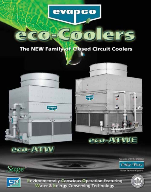
The <strong>eco</strong>-ATW & <strong>eco</strong>-ATWE<br />
is available with EVAPCO’s<br />
optional Pulse~Pure ®<br />
non-chemical water<br />
treatment system. The<br />
Pulse~Pure ® Patent #: 7,704,364<br />
Water<br />
Treatment System utilizes pulsed-power technology to<br />
provide CHEMICAL FREE Water Treatment and is an<br />
environmentally responsible alternative for treating<br />
water in evaporative cooled equipment. It does not<br />
release harmful by-products to the environment and<br />
eliminates costly chemicals completely from cooler<br />
drift and blowdown. The Pulse~Pure ® system<br />
delivers short, high-frequency bursts of low energy<br />
electromagnetic fields to the recirculating water in<br />
the <strong>eco</strong>-ATW & <strong>eco</strong>-ATWE and will:<br />
• Control Bacteria to Levels Well Below Most<br />
Chemical Water Treatment Programs.<br />
• Control the Formation of Mineral Scale on<br />
Heat-Exchange Surfaces.<br />
• Save Water by Operating at Higher Cycles of<br />
Concentration.<br />
• Yield Corrosion Rates Equivalent to Chemical<br />
Water Treatment.<br />
Because ongoing water<br />
treatment service is an<br />
absolute requirement for<br />
any evaporative cooled<br />
system, each purchase of<br />
a Pulse~Pure ® Water<br />
Treatment System includes, as standard, a 1 year<br />
water treatment service and monitoring contract<br />
provided by your EVAPCO Representative<br />
EVAPCO’s Pulse~Pure ® system<br />
offers <strong>eco</strong>-ATW & <strong>eco</strong>-<strong>ATWB</strong><br />
owners a single-source of<br />
responsibility for equipment,<br />
water treatment and service.<br />
More benefits of offering EVAPCO’s Pulse~Pure ®<br />
Water Treatment System on the new <strong>eco</strong>-ATW &<br />
<strong>eco</strong>-ATWE are:<br />
• Pulse~Pure ® Factory Mounting - Factory<br />
Installation of the Pulse~Pure ® System Guarantees<br />
Your Water Treatment is Installed to Factory<br />
Specifications.<br />
• Integral Cutting Edge Conductivity Control and<br />
Blowdown Packages that are contained in a single<br />
feeder panel:<br />
Conductivity Control Package – Measures<br />
Conductivity Utilizing a Non-Fouling Torodial Probe<br />
and Features:<br />
• One power connection of 120 volt or 460 volt is all<br />
that is required.<br />
• USB port for downloadable 60 day audit trail of<br />
system operation.<br />
• Self draining conductivity loop.<br />
Motorized Blowdown Valve – Standard for the most<br />
reliable operation in bleed control. Three-way valve<br />
operation provides good bleed flow without a<br />
standing column of water.<br />
7
O P T I O N A L E Q U I P M E N T<br />
Electric Water Level Control<br />
Closed circuit coolers may<br />
be ordered with an electric<br />
water level control in lieu<br />
of the standard mechanical<br />
float and make-up<br />
assembly. This package<br />
provides accurate control<br />
of water levels and does<br />
not require field<br />
adjustment.<br />
Stainless Steel Basin<br />
EVAPCO coolers have a modular design which allows specific<br />
areas to be enhanced for increased corrosion protection. The<br />
basin area of the cooler experiences turbulent mixing of air<br />
and water, in addition to silt build-up. In conjunction with the<br />
EVAPCOAT Corrosion Protection System, EVAPCO offers an<br />
optional Stainless Steel Basin. This option provides Type 304<br />
or 316 stainless steel for the entire basin area including the<br />
support columns of the cooler and the louver frames.<br />
The basin section provides structural support for the unit; it is<br />
also the part of the unit that is most prone to corrosion. For<br />
maximum protection against corrosion, EVAPCO can provide a<br />
Stainless Steel Basin as an affordable option.<br />
Self Supporting Working Platform<br />
EVAPCO coolers are available with a self-supporting platform<br />
with ladder, which may be easily installed in the field. This<br />
option offers significant savings compared to field<br />
constructed catwalks, which must be supported by a<br />
structure external to the unit. The platform may be installed<br />
on either side, or the end opposite the connections.<br />
Motor Davit<br />
In the event that a<br />
fan motor should<br />
need to be<br />
replaced, a motor<br />
davit is available<br />
from which a chain<br />
fall can be<br />
mounted to easily<br />
lower the motor to<br />
the ground.<br />
Remote Sump Configuration<br />
For units operating in areas where temperatures may be very<br />
low, or where low temperatures may occur during periods<br />
when the unit is not operating, a sump located inside the<br />
building is the preferred means of ensuring that the basin<br />
water will not freeze. For these applications, the cooler will<br />
be supplied without<br />
the spray pump,<br />
suction strainers and all<br />
associated piping, but<br />
is furnished with an<br />
oversized bottom<br />
outlet.<br />
Capacity Control<br />
Two Speed Motors<br />
Two speed fan motors can provide an excellent means of<br />
capacity control. In periods of lightened loads or reduced<br />
wet bulb temperatures, the fans can operate at low speed,<br />
which will provide about 60% of full speed capacity, yet<br />
consume only about 15% of the power compared with high<br />
speed. In addition to the energy savings, the sound levels of<br />
the units will be greatly reduced at low speed.<br />
8
O P T I O N A L E Q U I P M E N T<br />
Solutions for Sound Sensitive Applications<br />
The <strong>eco</strong>-ATW & <strong>eco</strong>-ATWE Closed Circuit Coolers are now available with four (4) equipment options to reduce the overall sound<br />
generated from the side or top of the <strong>eco</strong> Closed Circuit Cooler. Each option provides various levels of sound reduction and options<br />
can be combined to provide the lowest sound level. Consult EVAPCO’s evapSelect selection program for unit sound levels. If a<br />
detailed analysis or full octave band data sheet is required for your application, please consult your EVAPCO Sales Representative.<br />
NOTE: These low sound options may impact the overall installed dimensions of the <strong>eco</strong>-ATW & <strong>eco</strong>-ATWE Closed Circuit<br />
Cooler selected.<br />
Super Low Sound Fan<br />
9–15 dB(A) Reduction versus Standard Fan!<br />
The Super Low Sound<br />
Fan offered by EVAPCO<br />
uses an extremely wide<br />
chord blade design for<br />
very sound sensitive<br />
applications where the<br />
lowest sound levels are<br />
required. The fan is onepiece<br />
molded heavy duty<br />
FRP construction utilizing a forward swept blade design. The<br />
Super Low Sound fan is capable of reducing the unit sound<br />
pressure levels 9 dB(A) to 15 dB(A), depending on specific<br />
unit selection and measurement location. The fans are high<br />
efficiency axial propeller type.<br />
The Super Low Sound Fan is available on all 8.5 ft. and larger<br />
AT Cooling Towers, <strong>eco</strong>-ATW & <strong>eco</strong>-ATWE Closed Circuit<br />
Coolers, and ATC Evaporative Condensers.<br />
Low Sound Fan<br />
4–7 dB(A) Reduction!<br />
The Low Sound Fan offered by EVAPCO uses a wide chord<br />
blade design for sound sensitive applications where low<br />
sound levels are<br />
desired. Low Sound<br />
Fan construction<br />
uses aluminum<br />
blades and a steel<br />
fan hub. The Low<br />
Sound Fan is capable<br />
of reducing the unit<br />
sound pressure levels<br />
4 dB(A) to 7dB(A),<br />
depending on<br />
specific unit selection and measurement location. The fans<br />
are high efficiency axial propeller type.<br />
Fan Discharge Sound Attenuation<br />
Up to 10 dB(A) Reduction!<br />
The <strong>eco</strong>-ATW & <strong>eco</strong>-ATWE Fan Discharge Attenuator offered<br />
by EVAPCO is an additional option available to further reduce<br />
the sound level of the unit. The attenuator can be used with<br />
the standard <strong>eco</strong>-ATW & <strong>eco</strong>-ATWE fan or in combination<br />
with the Low Sound Fan option.<br />
The discharge attenuator is a factory-assembled straight-sided<br />
discharge hood designed to reduce overall discharge sound<br />
levels at full fan speed 5 dB(A) to 10 dB(A), depending on<br />
specific unit selection and measurement location. It is<br />
constructed of G-235<br />
galvanized steel as standard<br />
(options available for Type<br />
304 stainless steel) and<br />
includes insulated walls and<br />
a low pressure drop baffling<br />
system that is acoustically<br />
lined with high density<br />
fiberglass. The discharge<br />
attenuator is self-supported<br />
by the unit and is shipped<br />
loose for field mounting. A<br />
heavy-gauge, hot-dip galvanized steel fan guard covers the<br />
discharge attenuator to prevent debris from entering the<br />
attenuator.<br />
The discharge attenuator has minimal impact on unit thermal<br />
performance (0%-2% derate depending on specific unit<br />
selection).<br />
The Discharge Attenuator is available on: ALL standard AT<br />
Cooling Towers, <strong>eco</strong>-ATW & <strong>eco</strong>-ATWE Closed Circuit Coolers,<br />
and ATC Evaporative Condensers. It is also available on 12 ft.<br />
and 24 ft. wide AT, <strong>eco</strong>-ATW, <strong>eco</strong>-ATWE and ATC Models with<br />
the Low Sound Fan option.<br />
(Note: The <strong>eco</strong>-ATW & <strong>eco</strong>-ATWE Fan Discharge Attenuator<br />
Option is NOT available on <strong>eco</strong>-ATW & <strong>eco</strong>-ATWE Models<br />
provided with the Super Low Sound Fan.)<br />
Water Silencer<br />
Up to 7 dB(A) Reduction!<br />
The water silencer option is available for all <strong>eco</strong>-ATW &<br />
<strong>eco</strong>-ATWE models and is located in the falling water area of<br />
the cold water basin. The<br />
water silencer reduces the<br />
high frequency noise<br />
associated with the falling<br />
water and is capable of<br />
reducing overall sound<br />
levels 4 dB(A) to 7 dB(A)<br />
measured at 5 ft. from the<br />
side or end of the unit.<br />
The water silencers reduce<br />
overall sound levels 9 db(A) to 12 db(A) (depending on water<br />
loading and louver height) measured 5 ft. from the side or<br />
end of the unit when water is circulated with fans off.<br />
The water silencers are constructed of lightweight PVC sections<br />
and can be easily removed for access to the basin area.<br />
Consult EVAPCO’s Advanced Technology Low Sound<br />
Solutions Bulletin No. 650-US for detailed product and<br />
specification information.<br />
9
The<br />
Water and Energy<br />
Conservation<br />
Control System<br />
The only way to properly<br />
control and operate the<br />
<strong>eco</strong>-ATWE Closed Circuit<br />
Cooler is to provide, as<br />
®<br />
standard, the Sage3<br />
Water and Energy<br />
Conservation Control<br />
System. The Sage3 ® is<br />
designed to optimally<br />
control the fan motor(s)<br />
and the pump motors of<br />
the unit. The Sage3 ® will<br />
efficiently reject the<br />
building load using the<br />
minimal amount of water and energy.<br />
• Sophisticated control system that measures &<br />
analyses water inlet & outlet temperatures and the<br />
ambient dry bulb to minimize water consumption<br />
• Variable frequency drive controls for fan motor(s)<br />
• Maximizes water and energy savings<br />
NEW!<br />
Ellipti-fin<br />
Featuring Elliptical Spiral Fin Coil Technology<br />
Introducing the Most Efficient Closed Circuit Cooler Coil<br />
in the HVAC industry! The Ellipti-fin provides:<br />
• All coil rows feature patent pending finned Thermal-Pak elliptical<br />
tube design<br />
• Lower airflow resistance than typical finned round tubes<br />
• Increased Evaporative and Dry Cooling efficiency<br />
CTI Certified<br />
†<br />
Unique Fan Drive System<br />
• Power-band belts for better lateral rigidity<br />
• Advanced design aluminum fan blades<br />
• Non-corroding cast aluminum sheaves<br />
• Heavy-duty fan shaft bearings with L-10 life of<br />
75,000 - 135,000 hrs<br />
• All other components constructed of corrosion<br />
resistant materials<br />
• Totally enclosed fan motors assure long life<br />
Super Low Sound Fan<br />
(Optional)<br />
• Extremely wide sloped fan<br />
blades for sound sensitive<br />
applications.<br />
• One piece molded heavy duty<br />
construction.<br />
• 9-15 dB(A) sound reduction.<br />
10<br />
Patent #: 7,704,364<br />
Optional Pulse~Pure ®<br />
Water Treatment System<br />
• Control bacteria to levels well below traditional<br />
chemical water treatment<br />
• Control the formation of mineral scale<br />
• Save water by operating at higher cycles of<br />
concentration<br />
• Yield corrosion rates equivalent to chemical<br />
water treatment<br />
Certificate of Compliance<br />
AT, USS, UAT, UT Cooling Towers<br />
<strong>eco</strong>-ATW/WE, <strong>ATWB</strong> and ESWA Closed Circuit Coolers<br />
<strong>eco</strong>-ATC, ATC-E Evaporative Condensers<br />
Are certified to meet or exceed the Seismic and Wind Load Provisions<br />
set forth in the applicable building codes for this project.<br />
These products have been manufactured following all<br />
applicable quality assurance programs.<br />
Applicable Building Codes:<br />
Referenced Report:<br />
IBC 2006<br />
VMA-43387<br />
ASCE-7<br />
NFPA 5000<br />
Approval Agency:<br />
VMC Seismic Consulting Group<br />
EVAPCO...Specialists in Heat Transfer Products and Services. ID IBC COC 001<br />
IBC Certification<br />
Label<br />
• Provided with every<br />
unit to indicate<br />
independent<br />
certification<br />
and compliance<br />
Most<br />
Accessible<br />
Basin<br />
• Access from<br />
all four sides<br />
• Large open area simplifies maintenance<br />
• Basin may be inspected with pumps running<br />
Featuring… Louver Access Door<br />
• Louver access door is standard on models<br />
with 5 and 6 ft. louver sizes<br />
• Hinged access panel with quick release<br />
mechanism<br />
• Allows easy access to perform routine<br />
maintenance and inspection of the makeup<br />
assembly, strainer screen and basin
Design and Construction Features<br />
The New <strong>eco</strong>-ATWE line of Closed Circuit Coolers offers the same great design benefits and features as the<br />
<strong>eco</strong>-ATW but it has also been specifically designed to optimize both the evaporative (latent) and dry (sensible)<br />
modes of cooling simultaneously. This unique design joins an evaporative cooler and a dry cooler into one<br />
unit. The <strong>eco</strong>-ATWE utilizes the EVAPCO Ellipti-fin coil which features elliptical spiral fin technology to<br />
maximize the surface area available for heat transfer. This decreases water consumption and offers additional<br />
cost savings through reduced water make-up, blow-down, and<br />
chemical consumption. Evaporative cooling provides lower system<br />
operating temperatures and higher overall system efficiencies. The<br />
<strong>eco</strong>-ATW is the ideal solution for: Lower Energy Costs, Reducing<br />
Water Consumption, High Dry Bulb Switchover, Super Low Sound<br />
Levels. This new product is designed with IBC Compliant<br />
†<br />
construction and CTI Certified Performance.<br />
Efficient Drift Eliminators<br />
• Advanced design removes<br />
mist from the leaving<br />
airstream<br />
• Made from corrosion<br />
resistant PVC for long life<br />
(U.S. Patent No. 6315804)<br />
PVC Spray Distribution<br />
Header with ZM2 Nozzles<br />
• Nozzles are threaded into<br />
header at proper orientation<br />
• Large orifice fixed position<br />
nozzles prevent clogging<br />
• Threaded end caps for ease<br />
of cleaning<br />
Easy Field Assembly<br />
• A new field assembly seam design<br />
which ensures easier assembly<br />
and fewer field seam leaks<br />
• Self-guiding channels guide the coil<br />
casing section into position<br />
improving the quality of the field<br />
seam<br />
• Eliminated up to 66% of fasteners<br />
(Patent Pending)<br />
Partition Panel<br />
A water tight partition spans from<br />
the fan section of the unit down to<br />
the basin. This partition separates<br />
the two coils and ensures water<br />
does not contact the dry coil when<br />
the unit is operating in the water<br />
efficient mode.<br />
Multiple Water<br />
Distribution Systems<br />
Each coil in this unit features its<br />
own water distribution system.<br />
This allows each coil to operate<br />
in a mode independent of the<br />
other coil.<br />
NEW &<br />
Improved!<br />
WST II Air Inlet Louvers<br />
(Water and Sight Tight)<br />
• Easily removable for access<br />
• Improved design to keep<br />
sunlight out–preventing<br />
biological growth<br />
• Keeps water in while keeping<br />
dirt and debris out<br />
(Patent Pending)<br />
† Mark owned by the Cooling Technology Institute<br />
11
D ESIGN F EATURES<br />
Principles of Operation<br />
Evaporative Mode<br />
(Latent Heat Transfer)<br />
In the evaporative mode, the process fluid enters the<br />
<strong>eco</strong>-ATWE cooler through the top coil connections and<br />
circulates through the finned coils. With both pumps<br />
energized, the heat from the process fluid is transferred<br />
through the coil tubes to the water cascading downward<br />
over the coils while simultaneously air is drawn upward<br />
over the coil opposite the water flow using the fan drive<br />
system (Fan on, Pump A & B on). A small portion of the<br />
water is evaporated to dissipate the heat to the<br />
atmosphere in a latent heat transfer. This mode of<br />
operation provides fan energy savings and lower leaving<br />
water temperatures by utilizing evaporative cooling.<br />
Water Efficient Mode<br />
(Evaporative and Sensible Heat Transfer)<br />
The joint wet and dry operation mode provides water<br />
savings as well as low approach temperatures. In this joint<br />
mode of operation, the fan is on and the process fluid<br />
enters the coils through the top coil connections (Fan on,<br />
Pump A on, Pump B off). Recirculating pump B is turned off<br />
and coil B rejects a portion of the heat load to the<br />
atmosphere through the tube and fin walls to the air<br />
passing over the coils using sensible heat transfer. Pump A is<br />
left on where heat from the process fluid is transferred<br />
through the coil tubes to the water cascading downward<br />
over coil A. This mode of operation minimizes the amount<br />
of water used while maintaining the cooling capacity<br />
required. The cooled fluid then returns to the process via<br />
the bottom coil connection.<br />
Dry Mode<br />
(Sensible Heat Transfer)<br />
In the dry mode, the recirculating spray pumps are<br />
deenergized (Fan on, Pump A & B off). The process fluid<br />
enters the <strong>eco</strong>-ATWE cooler through the top coil connection<br />
and circulates through the coil with the Fan On. Heat from<br />
the process fluid is dissipated to the atmosphere by sensible<br />
heat transfer through the tube walls to the air passing over<br />
the coils. The coils are finned to promote optimal airflow<br />
over the coil and to maximize heat transfer area. Air is<br />
drawn over the finned coils by the fan drive system. The<br />
process fluid then returns to the heat source via the bottom<br />
coil connection. This mode of operation eliminates water<br />
consumption when the dry bulb temperature is favorable.<br />
12
S P E C I F I C AT I O N S<br />
SECTION 23 65 00 – FACTORY-FABRICATED CLOSED CIRCUIT COOLERS<br />
PART 1 – DESIGN CONDITIONS<br />
A. Furnish and install as shown on the plans on EVAPCO Model<br />
______ induced draft counterflow closed circuit cooler. Each<br />
unit shall be CTI Certified (with water) and have the capacity<br />
to cool ______ GPM of ______ from ______°F to______ °F with<br />
a _______ °F entering wet bulb temperature and a dry bulb<br />
switchover temperature of ______ °F (Dry Capacity is not CTI<br />
Certified).<br />
Optional: (If dry operating condition are different than the<br />
wet operating conditions)<br />
Each unit shall also cool ______ GPM of______ from______ °F<br />
to______ °F with a ______ °F entering dry bulb temperature.<br />
B. Controls shall be provided with unit. See Controls Technical<br />
Specifications.<br />
PART 2 – GENERAL<br />
2.1 RELATED DOCUMENTS<br />
A. Drawings and general provisions of the Contract, including<br />
General and Supplementary Conditions and Division 1<br />
Specification Sections, apply to this section.<br />
2.2 SUMMARY:<br />
A. This Section includes factory assembled and tested, closed<br />
circuit, induced draft counterflow cooling tower (also known<br />
as a closed circuit cooler).<br />
2.3 SUBMITTALS<br />
A. General. Submit the following:<br />
1. Certified drawings of the closed circuit cooler, sound data,<br />
r<strong>eco</strong>mmended steel support indicating weight loadings, wiring<br />
diagrams, installation instructions, operation and maintenance<br />
instructions, and thermal performance guarantee by the<br />
manufacturer.<br />
2.4 QUALITY ASSURANCE<br />
A. Verification of Performance:<br />
1. Test and certify closed circuit cooler thermal performance<br />
according to CTI Standard 201.<br />
2.Test and certify closed circuit cooler sound performance<br />
according to CTI ATC-128.<br />
B. Meet or Exceed energy efficiency per ASHRAE 90.1.<br />
2.5 WARRANTY<br />
A. Motor/Drive System: Five (5) year comprehensive warranty<br />
against materials and workmanship including motor, fan,<br />
bearings, mechanical support, sheaves, bushings and belt.<br />
B. Unit: One (1) year from start-up, not to exceed eighteen (18)<br />
months from shipment on the unit.<br />
PART 3 - PRODUCTS<br />
3.1 MANUFACTURERS<br />
A. Manufactures: Subject to compliance with requirements,<br />
provide closed circuit coolers manufactured by one of the<br />
following:<br />
1. EVAPCO, Inc.<br />
2. Approved Substitute<br />
3.2 MATERIALS<br />
A. Galvanized Sheet Steel casing and fan housing complying<br />
with ASTM A 653/A 653M and having G-235 designation.<br />
B. Optional Type 304 and/or 316 Stainless Steel as specified.<br />
3.3 INDUCED-DRAFT, COUNTERFLOW CLOSED CIRCUIT COOLERS<br />
A. Description: Factory assembled and tested, induced draft<br />
counterflow closed circuit cooler complete with coil, fan,<br />
louvers, accessories, and rigging supports.<br />
B. Closed Circuit Cooler Characteristics and Capacities: Refer to<br />
the Closed Circuit Cooler schedule.<br />
C. Fan(s):<br />
1. Type and Material: Axial propeller, individually adjustable<br />
wide chord blade extruded aluminum installed in a closely fitted<br />
cowl with venturi air inlet for maximum efficiency, covered with<br />
a heavy gauge hot dipped Galvanized Steel fan guard.<br />
2. Maximum sound pressure level of _____dB(A) measured at<br />
5 feet above the fan discharge during full speed operation<br />
in accordance with CTI Standard ATC-128.<br />
D. Water Distribution System: Non-corrosive materials.<br />
1. Each coil shall have a dedicated recirculation pump and<br />
water distribution system, which are completely separated<br />
by a water tight partition which begins above the water<br />
distribution systems and ends at the basin in order to allow<br />
for simultaneous wet and dry operation.<br />
2. Evenly distribute of water over coil with pressurized spray tree.<br />
a. Pipes: Schedule 40 PVC, Non-corrosive Materials<br />
b. Nozzles: Non-clogging, nylon, threaded into branch piping.<br />
E. IBC Compliance: The unit structure shall be designed,<br />
analyzed, and constructed in accordance with the latest<br />
edition of the International Building Code (IBC) Regulations<br />
for seismic loads up to _____ g and wind loads up to __ psf.<br />
F. Collection Basin Material: Galvanized Steel. Type 304/316<br />
Stainless Steel Optional:<br />
1. Removable stainless-steel strainer with openings smaller<br />
than nozzle orifices.<br />
2. Joints: Bolted and sealed watertight or welded.<br />
3. Overflow, makeup and side drain connections<br />
G. Heat Transfer Coil: Each row of the heat exchanger coil<br />
shall be provided with elliptical spiral fins to increase the<br />
evaporative and dry thermal performance of the unit as<br />
well as lowering the air pressure drop. Cooling coil(s) shall<br />
be all primed surface steel, encased in a steel framework<br />
and hot-dip galvanized after fabrication as a complete<br />
assembly. The tubes shall be arranged in a self-spacing,<br />
staggered pattern in the direction of airflow for<br />
maximum heat transfer efficiency and minimum pressure<br />
drop. The coil(s) shall be pneumatically ested at 400 psig,<br />
under water.<br />
H. Casing: Galvanized Steel. Type 304/316 Stainless Steel Optional:<br />
1. Casing panels shall totally encase the heat transfer coil.<br />
2. Fasteners: Corrosion resistance equal to or better than<br />
materials being fastened.<br />
3. Joints: Sealed watertight.<br />
4. Welded Connections: Continuous and watertight<br />
I. Drift Eliminators: PVC, for long life and durability resistant to<br />
rot, decay and biological attack; formed, bonded together<br />
for strength and durability in block format for easy removal<br />
and replacement; self extinguishing with flame spread<br />
rating of 5 per ASTM E84-81a; 0.001% drift rate.<br />
J. Air Inlet Louvers: Formed PVC; designed “Sight Tight” to<br />
completely block direct sunlight from entering and water<br />
from splashing out of the closed circuit cooler.<br />
K. Water Level Control: Brass mechanical makeup water valve<br />
and plastic float with an adjustable linkage.<br />
L. Water Recirculation Pump: Close-coupled, centrifugal type<br />
with mechanical seal. The pump motor shall be ESA<br />
Compliant, ____ horsepower totally enclosed for outdoor<br />
service on ____ volts, ____ hertz, and ____ phase.<br />
3.4 MOTORS AND DRIVES<br />
A. General requirements for motors are specified in Division 15<br />
Section “Motors”.<br />
B. Enclosure Type: TEAO or TEFC<br />
C. Fan Motor Speed: Premium Efficient VFD Duty (Option: 2-speed)<br />
1. Motors shall be provided with space heaters.<br />
D. Drive: Power Band Belt designed for 150% of the motor<br />
nameplate HP.<br />
1. Belt: Mutli-groove, solid back V-belt type neoprene<br />
reinforced with polyester cord.<br />
2. Sheaves: Aluminum alloy if located inside the airstream.<br />
3. Bearings: Heavy duty, self-aligning pillow block bearings<br />
with lubrication lines extended to side access door.<br />
Minimum L10 life for bearings shall be 75,000 hours. Provide<br />
extended grease lines and fittings.<br />
4. Vibration Cutout Switch: (optional) Mechanical switch to deenergize<br />
fan motors if excessive vibration in NEMA 4 enclosure.<br />
3.5 MAINTENANCE ACCESS<br />
A. Internal Working / Service Platforms: Provide a complete<br />
internal working platform and ladder system for service of all<br />
drive components. A suitable working platform may be<br />
constructed of the heat transfer coil for counterflow closed<br />
circuit coolers. If a crossflow cooler is used, provide an internal<br />
walkway with ladder and elevated working platform to allow<br />
for service and maintenance to motor and drive assembly.<br />
B. Handrails/Grabrails: Galvanized steel pipe complying with 29<br />
CFR 1910.23. If access to fan deck is required, supply a perimeter<br />
handrail with ladder from grade to fan deck.<br />
C. Ladders: (optional) Aluminum, sloped “ships type” with<br />
grabrail or vertical complying with 29 CFR 1910.27.<br />
13
SAGE SYSTEM<br />
EVAPCO’s<br />
… Water and Energy<br />
The EVAPCO <strong>eco</strong>-ATW closed circuit coolers utilize the optional<br />
Sage 2® water and energy conservation control system which controls<br />
Dry & Evaporative modes of operation. The <strong>eco</strong>-ATWE is provided<br />
standard with the Sage 3® control panel which controls Dry, Water<br />
Efficient and Evaporative modes of operation. The control system<br />
operates by measuring and analyzing water inlet and outlet<br />
temperature simultaneous with ambient dry bulb monitoring in<br />
order to minimize the evaporative cooling mode of operation and<br />
to save system water. The Sage can also be programmed to operate<br />
with a water savings or energy savings priority.<br />
The Sage Controller features a NEMA 4 enclosure with UL approval.<br />
The panel also includes a 10" touch screen operator interface with<br />
color display and a Modbus 485* data port for communication with<br />
the building automation system. The data points are: Inlet<br />
Temperature, Outlet Temperature, Dry Bulb Temperature, Basin<br />
Water Temperature Sensor, Fan Run Time, Pump Run Time, VFD<br />
Speed, Fan Motor Status – On/Off, Fan RPM, Pump Status – On/Off.<br />
Standard Control Items<br />
• A MODBUS 485* Port for the Building<br />
Automation System<br />
• Programmable Logic Control<br />
• Fluid Inlet Temperature Sensor(s)<br />
• Fluid Outlet Temperature Sensor(s)<br />
• Basin Temperature Sensor(s)<br />
• Ambient Dry Bulb Sensor(s)<br />
• Variable Frequency Drive(s) for Fan Motor(s)<br />
• Recirculating Pump Motor Starter(s).<br />
• Main Disconnect<br />
• Manual Bypass<br />
• DC Power Supply for the PLC and<br />
Instrumentation.<br />
• Heater Package Controls w/ Contactor with<br />
Overload Protection<br />
• Control Power Transformer<br />
• 5-Probe Electronic Water Level Control Package<br />
• High Water Level Alarm Contact(s)<br />
• Low Water Level Alarm Contact(s)<br />
• Fan Motor: Space Heater Control(s)<br />
Control for Optional Accessories<br />
• Discharge Hood Damper Controls<br />
• Vibration Switch Controls<br />
14
SAGE SYSTEM<br />
Conservation Control System<br />
HMI Panel Display<br />
All Sage 2® and Sage 3® Control Panels are provided with a<br />
10” touch screen operator interface with a color display.<br />
This allows for easy viewing and control at the panel.<br />
Window Enclosure<br />
The display screen is encased by a window enclosure. This<br />
enclosure protects the HMI display from the elements.<br />
Easy-to-use Touch Screen Navigation<br />
The panel boasts an easy to navigate menu which will allow<br />
the user to control each cell independently from other units<br />
and gather useful run time information at the unit.<br />
Alarm Setpoints Screen<br />
Electric Water Level Control Package<br />
When a Sage ® Panel is provided, a 5-probe Electronic Water<br />
Level Controller is standard. In addition to controlling the<br />
make-up valve, this controller contains two probes that can be<br />
utilized as High/Low water alarms. This controller will also be<br />
used as a safety device, shutting off the pump and heaters if<br />
the water level b<strong>eco</strong>mes too low.<br />
Temperature Sensors<br />
Four separate temperature data points are monitored with<br />
this package.<br />
• Inlet Temperature Sensor: 32ºF – 212ºF range<br />
• Outlet Temperature Sensor: 32ºF – 212ºF range<br />
• Dry Bulb Temperature Sensor: -30ºF – 130ºF range<br />
• Basin Temperature Sensor: 32ºF – 212ºF range<br />
Enclosure Temperature Control<br />
The panel enclosure includes an intake and an exhaust<br />
ventilation fan. When the enclosure temperature rises to a<br />
predetermined set point, the exhaust fans are activated. The<br />
enclosure also contains a heater. The heater eliminates the<br />
drastic temperature changes which could create condensation<br />
inside of the enclosure.<br />
Plan View Screen<br />
Fan<br />
Heater<br />
End View Screen<br />
*Optional Communication Protocol May Be Available.<br />
Please Contact Your Local Sales Representative.<br />
15
D ESIGN F EATURES<br />
<strong>eco</strong>-ATW Operating Benefits<br />
The <strong>eco</strong>-ATW features the new EVAPCO Ellipti-fin coil, which<br />
utilizes elliptical spiral fin coil technology. This technology allows<br />
for a significant increase in thermal performance with up to a<br />
40% lower operating horsepower (HP) than a typical<br />
evaporative cooler! This will results in tremendous energy<br />
savings throughout the year.<br />
If minimizing the footprint of the unit is of greater concern, the<br />
increased thermal capacity of the Ellipti-fin technology will<br />
allow a selection that yields up to a 40% smaller plan area!<br />
Additionally, the Ellipti-fin coil technology enables the <strong>eco</strong>-ATW<br />
to be operated in a 100% Dry Mode, whereby the switchover<br />
temperature is significantly higher than that of a typical bare<br />
tube coil. This leads to a significant increase in dry operating<br />
hours, thus increasing your water savings. This combination of<br />
features allows the <strong>eco</strong>-ATW to be operated with both energy<br />
and water efficiency in mind, making it the ideal choice for<br />
many installations.<br />
<strong>eco</strong>-ATWE Operating Benefits<br />
The <strong>eco</strong>-ATWE maintains all of the advantages of the <strong>eco</strong>-ATW<br />
with the additional benefit of enabling simultaneous wet and dry<br />
operation. The unique Water Efficient Mode of the <strong>eco</strong>-ATWE<br />
allows for a portion of the heat load to be rejected through both<br />
evaporative cooling AND dry cooling, even at high ambient<br />
temperatures, this further increases your ability to save water and<br />
offers additional associated cost savings through reduced water<br />
make-up, blow-down and chemical consumption. The <strong>eco</strong>-ATWE<br />
provides an ideal solution for applications where minimizing both<br />
energy and water consumption is critical.<br />
Depending on the optimum <strong>eco</strong>-Cooler you select for your job, one<br />
can operate 100% wet, 100% dry or simultaneously Wet & Dry in<br />
the Water Efficient Mode, offering unique advantages in freezing<br />
climates, higher temperature industrial cooling applications where<br />
100% evaporative cooling is not always favorable.<br />
<strong>eco</strong>-ATW & <strong>eco</strong>-ATWE Operational Savings:<br />
Consider a Data Center cooling application for Minneapolis, MN<br />
where the unit is required to reject a constant heat load of 216<br />
tons with 650 gpm of water entering at a temperature of 95°F and<br />
a leaving temperature of 85°F. The process operates 24 hours a<br />
day 7 days a week. Both the <strong>eco</strong>-ATW and the <strong>eco</strong>-ATWE are<br />
compared to:<br />
• Cooler A – an evaporative cooler without dry cooling capability<br />
• Cooler B– an induced draft counter-flow cooler capable of<br />
some dry operation<br />
Model Attribute Comparison<br />
<strong>eco</strong>-ATW <strong>eco</strong>-ATWE<br />
12-6L12-Z 12-6L12-Z Cooler A Cooler B<br />
Fan Motor HP 25 25 25 (2) 20<br />
Spray Pump HP 5 (2) 2 10 (2) 3<br />
Box Size (ft) 12x12 12x12 12x12 17x12<br />
Weight (lbs.) 27,530 28,115 24,880 39,700<br />
The <strong>eco</strong>-Coolers require lower pump HP than Cooler A and<br />
lower pump HP and fan HP than Cooler B. Additionally, the<br />
<strong>eco</strong>-Coolers provide either a similar or smaller footprint along<br />
with the HP savings.<br />
With the increased dry cooling efficiency of the <strong>eco</strong>-ATW and<br />
<strong>eco</strong>-ATWE and the use of the Sage ® Water and Energy<br />
Conservation Control System, each unit is able to operate dry for<br />
48.00% of the year. Additionally, the revolutionary design of the<br />
<strong>eco</strong>-ATWE allows the unit to operate in a Water Efficient Mode<br />
for an additional 47.9% of the year, further reducing water<br />
consumption. This is illustrated below:<br />
Degrees Fahrenheit<br />
Yearly Temperature Curve<br />
Monthly Water Usage Comparison<br />
Dry Mode of Operation Comparison<br />
<strong>eco</strong>-ATW <strong>eco</strong>-ATWE<br />
12-6L12-Z 12-6L12-Z Cooler A Cooler B<br />
Dry Bulb Switchover ºF 46.22 46.22 NA 33.44<br />
% Dry Operation (Hrs.) 48.00% 48.00% NA 31.00%<br />
% Water Efficient Mode<br />
(Hrs.) NA 47.90% NA NA<br />
Due to the Dry Operation capabilities of the <strong>eco</strong>-Coolers and<br />
the added Water Efficient Mode of the <strong>eco</strong>-ATWE the reduced<br />
costs associated with water usage is illustrated below:<br />
Annual Water Cost Comparisons<br />
<strong>eco</strong>-ATW <strong>eco</strong>-ATWE<br />
12-6L12-Z 12-6L12-Z Cooler A Cooler B<br />
Total Annual Water<br />
Usage* (gallons) 2,609,876 1,897,074 5,753,899 3,568,387<br />
% Savings vs. Cooler A / 54.64% / 67.03% / - / 37.98% /<br />
Cooler B 26.86% 46.84% - -<br />
Annual Water Savings $18,684 / $23,140 / - / $8,132 /<br />
vs. Cooler A / Cooler B** $5,751 $10,027 - -<br />
*Based on 3 cycles of concentration<br />
**$0.006 per gallon (Water & Sewer)<br />
Summarizing these costs, the <strong>eco</strong>-Coolers will save the<br />
operator a minimum of $18, 864 per year in associated water<br />
costs vs. a typical cooler and up to $10,000 vs. an induced<br />
draft counter-flow cooler with some dry capacity.<br />
16
N O T E S<br />
17
IBC COMPLIANCE<br />
In its continuing commitment to be the leaders in evaporative cooling equipment design and services,<br />
EVAPCO <strong>ATWB</strong> Closed Circuit Coolers are now Independently Certified to withstand both Seismic<br />
and Wind Loads in ALL Geographic Locations and Installations in accordance with IBC 2006.<br />
What is IBC?<br />
International Building Code<br />
The International Building Code (IBC) is a comprehensive<br />
set of regulations addressing both the structural design<br />
and the installation requirements for building systems –<br />
including HVAC and industrial refrigeration equipment.<br />
The IBC is intended to replace BOCA’s The National<br />
Building Code, ICBO’s Uniform Building Code and SBCCI’s<br />
Standard Building Code.<br />
Compared to previous building codes that considered<br />
only the building structure and component anchorage,<br />
the requirements contained within the IBC address<br />
anchorage, structural integrity, and the operational<br />
capability of a component following either a seismic or<br />
wind load event. Simply stated, the IBC code<br />
provisions require that evaporative cooling<br />
equipment, and all other components permanently<br />
installed on a structure, must be designed to meet<br />
the same seismic and wind load forces as the<br />
building to which they are attached.<br />
How Does IBC 2006 Apply to Closed<br />
Circuit Coolers?<br />
Based on the project zip code and site design factors,<br />
calculations are made to determine the equivalent<br />
seismic “g force” and wind load (in pounds per square<br />
foot – psf) on the unit. The closed circuit cooler must be<br />
designed to withstand the greater of either the seismic or<br />
wind load.<br />
The New <strong>ATWB</strong> is offered with a choice of TWO<br />
structural design packages:<br />
• Standard Structural Design – For projects with<br />
≤ 1.0g seismic or 145 psf wind loads<br />
• Upgraded Structural Design – Required for<br />
projects with > 1.0g seismic or 145 psf max wind<br />
loads<br />
More than 80% of the United States has design criteria<br />
resulting in a seismic design force of 1.0g or below. These<br />
sites will be provided with the standard <strong>ATWB</strong> structural<br />
design. An upgraded structural design is available for<br />
installations with design criteria resulting in “g forces”<br />
greater than 1.0g. The highest “g force” location in<br />
North America is 5.12g. The highest wind load shown on<br />
the maps is 170 mph, which is approximately equal to 145<br />
psf velocity pressure. Therefore, the upgraded<br />
structural design package option for the New <strong>ATWB</strong><br />
is designed for 5.12g and 145 psf making it<br />
applicable to ALL building locations in North<br />
America.<br />
Seismic Design<br />
The attached chart from the US Geological Survey<br />
Website (http://www.usgs.gov/) shows the potential<br />
seismic activity in the United States. Buildings constructed<br />
in the red, orange and yellow areas of the map may<br />
require the upgraded <strong>ATWB</strong> construction design based<br />
on the site seismic design factors and should be reviewed<br />
closely. Critical use facilities, such as hospitals, are also<br />
more likely to require the upgraded design.<br />
Map courtesy US Geological Survey website<br />
Highest Hazard<br />
32+<br />
24-32<br />
16-24<br />
%g 8-16<br />
4-8<br />
2-4<br />
0-2<br />
Lowest Hazard<br />
The project architect or civil engineer is responsible for<br />
determining the seismic design factors to be used for the<br />
building design. A mechanical consulting engineer and/or<br />
design build contractor then applies these factors to a<br />
series of charts and graphs to determine the appropriate<br />
seismic design factors based on the location of the<br />
installation and ultimately the “importance” of the<br />
facility. The specific factors necessary for seismic design as<br />
well as a sample seismic calculation are shown on the<br />
next page.<br />
18
IBC COMPLIANCE<br />
Wind Design<br />
The IBC 2006 code book includes a map of basic wind<br />
speed (3-s<strong>eco</strong>nd gust) by contour lines. However, local<br />
regulations may be more stringent than these published<br />
speeds. The specific factors necessary for wind load as well<br />
as a sample wind load calculation are shown on Page 16.<br />
Whichever design force - seismic or wind - is more<br />
severe for the building, governs the design of the<br />
building and all attached equipment.<br />
demonstrates that the equipment has been independently<br />
tested and analyzed in accordance with the IBC seismic and<br />
wind load requirements. <strong>Evapco</strong> has worked closely with<br />
the independent approval agency, The VMC Group, to<br />
complete the independent equipment testing and analysis.<br />
If the seismic “g force” and wind “psf” load requirements<br />
for the project site are known, EVAPCO’s online<br />
equipment selection software, iES, will allow you to<br />
choose the required structural design package – either<br />
standard construction or upgraded construction.<br />
If the project requirements are unknown, the following<br />
calculations must be completed.<br />
For further questions regarding IBC compliance, please<br />
contact your local EVAPCO Representative or visit<br />
www.evapco.com.<br />
When using the EVAPCO selection software to make a<br />
selection, these calculations are already incorporated<br />
into the selection process. Simply enter the required<br />
seismic factors and the Seismic Design Force and Wind<br />
Load will be calculated automatically!!<br />
Wind Load Map Courtesy IBC 2006 Text –<br />
See full-sized map for location specific values<br />
Design Implementation<br />
EVAPCO applies the given seismic and wind load<br />
information provided by the mechanical consulting<br />
engineer to determine the equipment design necessary<br />
to meet IBC requirements. This process ensures that the<br />
mechanical equipment and its components are compliant<br />
per the provisions of the IBC as given in the plans and<br />
specifications for the project. For design build projects,<br />
EVAPCO is equipped to look up the information and<br />
submit the resulting loads for approval.<br />
Independent Certification<br />
Per the most recent edition of the code, the EVAPCO<br />
compliance process included an exhaustive analysis by an<br />
independent approval agency. As required by the<br />
International<br />
Building Code,<br />
EVAPCO<br />
supplies a<br />
certificate of<br />
compliance as<br />
part of its<br />
submittal<br />
documents. The<br />
certificate of<br />
compliance<br />
Seismic Load Calculations<br />
The data required to calculate the seismic load are:<br />
Occupancy Category – I, II, III or IV depending on the<br />
nature of the building occupancy. Table 1604.5 in the IBC<br />
2006 Code Book defines each of the four categories in<br />
detail. In summary the four categories are:<br />
• Category I - structures that represent a low hazard<br />
to human life in the event of a failure.<br />
• Category III - structures that represent a substantial<br />
hazard to human life in the event of a failure.<br />
• Category IV - structures designated as essential<br />
facilities.<br />
• Category II - any structures not listed in I, III or IV.<br />
Site Classification – A, B, C, D, E or F based on the types<br />
of soil and their engineering properties. Table 1613.5.2<br />
in the IBC 2006 Code Book defines each of the categories<br />
in detail. IBC specifies site class “D” when soil properties<br />
are unknown.<br />
Maximum Spectral Response Acceleration (Ss) –<br />
Numerical value found using the U.S. Geological (USGS)<br />
data based on the Zip Code of the project. This data<br />
point can be determined using the Ground Motion<br />
Parameter Calculator at http://www.usgs.gov/. Note the<br />
calculator assumes a site classification of B for the 0.2<br />
s<strong>eco</strong>nd maximum Ss. The site coefficient (Fa), defined<br />
below, will correct for the actual site classification.<br />
19
IBC COMPLIANCE<br />
Site Coefficient (Fa) – Values ranging from 0.8 to 2.5<br />
determined based on the Ss and the Site Classification.<br />
Table 1613.5.3(1) in the IBC 2006 Code Book defines<br />
these values.<br />
Design Spectral Response Acceleration (SDS) – A<br />
calculated value using the values for Ss and Fa.<br />
Amplification Factor (ap) – 2.5 for flexible components<br />
or flexibly attached components. Due to its low inherent<br />
natural frequencies, most evaporative cooling equipment<br />
falls under the definition of flexible. Therefore the<br />
default for Closed Circuit Coolers is 2.5. See Table 13.6-1<br />
in the American Society of Civil Engineers (ASCE)<br />
Standard 7-05, to which IBC often references, for more<br />
information.<br />
Response Modification Factor (Rp) – 2.5 for nonisolated<br />
evaporative cooling equipment. 2.0 for vibration<br />
isolated evaporative cooling equipment. Table 13-6.1 of<br />
ASCE 7-05 provides additional information.<br />
Component Operating Weight (Wp) – This weight<br />
term has been removed from the equation below,<br />
because EVAPCO is expressing the force in terms of g’s<br />
and not lbs.<br />
Importance Factor (Ip) – 1.5 for Occupancy Category IV,<br />
life safety components required to function after a<br />
seismic event or component containing hazardous<br />
content. 1.0 for all other components. ASCE 7-05 Section<br />
13.1.3 provides additional detail on importance factors.<br />
Installation Location (Z/h) – 0 for units installed at<br />
ground level. 1.0 for units installed on a rooftop. Per<br />
ASCE 7-05 Section 13.3, z = the height of the point of<br />
attachment of the component and h = the relative roof<br />
height.<br />
Seismic Design Force, (Fp) – “G-force” that the unit<br />
must be able to withstand. This number is calculated<br />
using the factors described above. The New <strong>ATWB</strong> is<br />
offered with a choice of two structural design packages,<br />
consisting of:<br />
– Standard Structural Design ≤ 1.0g<br />
– Upgraded Structural Design – up to 5.12g (the<br />
maximum value for North America)<br />
Seismic Load Sample Calculation<br />
The following example demonstrates the procedure for<br />
determining which structural design package a<br />
Community Hospital located in Charleston, SC (zip code<br />
29401) would require under the latest version of IBC. In<br />
this example, the closed circuit cooler will be installed on<br />
a roof, approximately 60 feet above grade. The unit will<br />
also be installed with a vibration isolation system.<br />
Step 1: Calculate the Design Spectral Response<br />
Acceleration (SDS)<br />
Where:<br />
SS = 1.495; using the USGS Ground Motion Parameter<br />
Calculator<br />
Fa = 1.0; from Table 1613.5.3(1) in the IBC 2006 Code<br />
Book assuming a Site Classification of D<br />
Step 2: Calculate the Seismic Design Force (Fp )<br />
Where:<br />
ap = 2.5; the default for cooling towers and closed<br />
circuit coolers<br />
SDS = 0.9966; as calculated in Step 1<br />
Wp = 1.0; the default for cooling towers and closed<br />
circuit coolers<br />
Rp = 2.0; the default for isolated equipment<br />
Ip = 1.5; the default for life safety components<br />
z/h = 1.0; the default for units on a rooftop<br />
In order to meet Code requirements, the unit and its<br />
anchorage must be constructed to withstand 2.24g. This<br />
will require that the upgraded structure option be chosen<br />
to meet the seismic requirements of this project. Because<br />
the seismic load requires the upgraded structural design,<br />
the wind load calculation results will not change the<br />
design and are not required for this analysis.<br />
20
IBC COMPLIANCE<br />
Wind Load Calculations<br />
Note, both the standard construction and the upgraded<br />
construction <strong>ATWB</strong> Closed Circuit Cooler are designed to<br />
meet a wind load of 145 psf. Therefore, the following<br />
details are provided for informational purposes only.<br />
The data required to calculate the wind load are:<br />
Basic Wind Speed (V) – Numerical value, in miles per<br />
hour (mph) found in ASCE 7-05 Figures 6-1 (A,B,C).<br />
Wind Directionality Factor (Kd) – 0.85 for building<br />
components and cladding. Table 6-4 of ASCE 7-05<br />
provides additional information.<br />
Occupancy Category – I, II, III or IV depending on the<br />
nature of the building occupancy. Table 1604.5 in the<br />
IBC 2006 Code Book defines each of the categories in<br />
detail. This is the same Occupancy Category used in<br />
Seismic calculations.<br />
Importance Factor (I) – Numerical value between 0.77<br />
and 1.15 based on the Basic Wind Speed and the<br />
Occupancy Category. These values are found in Table 6-1<br />
of ASCE 7-05.<br />
Exposure Category – B, C or D as defined in Section<br />
6.5.6.3 of ASCE 7-05.<br />
Component Elevation (z) – The anchorage height of<br />
the unit in feet.<br />
Nominal Height of the Atmospheric Boundary Layer<br />
(zg) - Numerical value based on Exposure Category. These<br />
values are found in Table 6-2 of ASCE 7-05.<br />
3 s<strong>eco</strong>nd Gust-Speed power Law Exponent (α) -<br />
Numerical value based on Exposure Category. These<br />
values are found in Table 6-2 of ASCE 7-05.<br />
Velocity Pressure Exposure Coefficient (Kz) – A<br />
calculated value using the values for zg and α.<br />
z<br />
KZ = 2.01( zg)<br />
2<br />
( a )<br />
Wind Load Sample Calculation<br />
The following example demonstrates the procedure to<br />
determine which structural design package a<br />
Condominium Building located in Miami, FL (zip code<br />
33101) would require under the latest version of IBC. In<br />
this example, the closed circuit cooler will be installed on<br />
the top of the 60 foot tall building.<br />
Step 1: Calculate the Exposure Category Coefficient (Kz)<br />
Where:<br />
z = 60; Installation Height<br />
zg = 700; from ASCE 7-05 Table 2 using an Exposure<br />
Category of D.<br />
α = 11.5; from ASCE 7-05 Table 2 using an Exposure<br />
Category of D.<br />
Step 2: Calculate the Velocity Pressure (qz)<br />
Where:<br />
KZ = 2.01<br />
( a )<br />
( )<br />
( 11.5)<br />
2 2<br />
z<br />
60<br />
=<br />
( zg) 2.01 =<br />
700<br />
1.31<br />
qz = 0.00256(Kz)(Kzt)(Kd)(V 2 )(I) =<br />
0.00256(1.31)(1.0)(0.85)(145 2 )(1.0) = 59.93psf<br />
Kz = 1.31; as calculated above.<br />
Kzt = 1.0; default when topographic effects are not a<br />
factor.<br />
Kd = 0.85; default for building components and<br />
cladding.<br />
V = 145; wind speed from ASCE 7-05 Figure 6-1.<br />
I = 1.0; Based on an Occupancy Category of II.<br />
Topographic Factor (Kzt) – 1.0 default when<br />
topographic effects are not a factor. ASCE 7-05 Section<br />
6.5.7 provides additional detail on topographic factors.<br />
Velocity Pressure (qz) – This number in pounds per<br />
square foot (psf) is calculated using the factors described<br />
above. The New <strong>ATWB</strong> is offered with a choice of two<br />
structural design packages, consisting of:<br />
– Standard Design and Upgraded Structural Design –<br />
both up to 145 psf (the maximum value for North<br />
America)<br />
In order to meet Code requirements, the unit and its<br />
attachments must be designed and constructed to<br />
withstand 59.93 psf. Because the wind load does not<br />
dictate the closed circuit cooler design, the seismic load<br />
calculation must also be completed to determine if the<br />
results will change the unit design.<br />
21
22<br />
N O T E S
EVAPCO PRODUCTS ARE MANUFACTURED WORLDWIDE<br />
World Headquarters/<br />
Research and<br />
Development Center<br />
EVAPCO Facilities<br />
EVAPCO North America<br />
EVAPCO, Inc.<br />
World Headquarters<br />
P.O. Box 1300<br />
Westminster, MD 21158 USA<br />
Phone: 410-756-2600<br />
Fax: 410-756-6450<br />
E-mail: marketing@evapco.com<br />
EVAPCO East<br />
5151 Allendale Lane<br />
Taneytown, MD 21787 USA<br />
Phone: 410-756-2600<br />
Fax: 410-756-6450<br />
E-mail: marketing@evapco.com<br />
EVAPCO Midwest<br />
1723 York Road<br />
Greenup, IL 62428 USA<br />
Phone: 217-923-3431<br />
Fax: 217-923-3300<br />
E-mail: evapcomw@evapcomw.com<br />
EVAPCO West<br />
1900 West Almond Avenue<br />
Madera, CA 93637 USA<br />
Phone: 559-673-2207<br />
Fax: 559-673-2378<br />
E-mail: contact@evapcowest.com<br />
EVAPCO Iowa<br />
925 Quality Drive<br />
Lake View, IA 51450 USA<br />
Phone: 712-657-3223<br />
Fax: 712-657-3226<br />
EVAPCO Iowa<br />
Sales & Engineering<br />
1234 Brady Boulevard<br />
Owatonna, MN 55060 USA<br />
Phone: 507-446-8005<br />
Fax: 507-446-8239<br />
E-mail: evapcomn@evapcomn.com<br />
EVAPCO, Inc. — World Headquarters & Research/Development Center<br />
EVAPCO, Inc. • P.O. Box 1300 • Westminster, MD 21158 USA<br />
PHONE: 410-756-2600 • FAX: 410-756-6450 • E-MAIL: marketing@evapco.com<br />
Refrigeration Valves &<br />
Systems Corporation<br />
A wholly owned subsidiary of EVAPCO, Inc.<br />
1520 Crosswind Dr.<br />
Bryan, TX 77808 USA<br />
Phone: 979-778-0095<br />
Fax: 979-778-0030<br />
E-mail: rvs@rvscorp.com<br />
McCormack Coil Company, Inc.<br />
A wholly owned subsidiary of EVAPCO, Inc.<br />
P.O. Box 1727<br />
6333 S.W. Lakeview Boulevard<br />
Lake Oswego, OR 97035 USA<br />
Phone: 503-639-2137<br />
Fax: 503-639-1800<br />
E-mail: mail@mmccoil.com<br />
EvapTech, Inc.<br />
A wholly owned subsidiary of EVAPCO, Inc.<br />
8331 Nieman Road<br />
Lenexa, KS 66214 USA<br />
Phone: 913-322-5165<br />
Fax: 913-322-5166<br />
E-mail: marketing@evaptech.com<br />
Tower Components, Inc.<br />
A wholly owned subsidiary of EVAPCO, Inc.<br />
5960 US HWY 64E<br />
Ramseur, NC 27316<br />
Phone: 336-824-2102<br />
Fax: 336-824-2190<br />
E-mail: mail@towercomponentsinc.com<br />
EVAPCO Newton<br />
701 East Jourdan Street<br />
Newton, IL 62448 USA<br />
Phone: 618-783-3433<br />
Fax: 618-783-3499<br />
E-mail: evapcomw@evapcomw.com<br />
EVAPCO...SPECIALISTS IN HEAT TRANSFER<br />
PRODUCTS AND SERVICES.<br />
EVAPCO Europe<br />
EVAPCO Europe, N.V.<br />
European Headquarters<br />
Industrieterrein Oost 4010<br />
3700 Tongeren, Belgium<br />
Phone: (32) 12-395029<br />
Fax: (32) 12-238527<br />
E-mail: evapco.europe@evapco.be<br />
EVAPCO Europe, S.r.l.<br />
Via Ciro Menotti 10<br />
I-20017 Passirana di Rho<br />
Milan, Italy<br />
Phone: (39) 02-939-9041<br />
Fax: (39) 02-935-00840<br />
E-mail: evapcoeurope@evapco.it<br />
EVAPCO Europe, S.r.l.<br />
Via Dosso 2<br />
23020 Piateda Sondrio, Italy<br />
EVAPCO Europe, GmbH<br />
Bovert 22<br />
D-40670 Meerbusch, Germany<br />
Phone: (49) 2159-69560<br />
Fax: (49) 2159-695611<br />
E-mail: info@evapco.de<br />
Flex coil a/s<br />
A subsidiary of EVAPCO, Inc.<br />
Knøsgårdvej 115<br />
DK-9440 Aabybro Denmark<br />
Phone: (45) 9824 4999<br />
Fax: (45) 9824 4990<br />
E-mail: info@flexcoil.dk<br />
EVAPCO S.A. (Pty.) Ltd.<br />
A licensed manufacturer of EVAPCO, Inc.<br />
18 Quality Road<br />
Isando 1600<br />
Republic of South Africa<br />
Phone: (27) 11 392-6630<br />
Fax: (27) 11-392-6615<br />
E-mail: evapco@evapco.co.za<br />
Evap Egypt Engineering Industries Co.<br />
5 El Nasr Road, Nasr City, Cairo, Egypt<br />
Phone: +2 (02) 24022866/+2 (02) 24044997/8<br />
Fax: +2 (02) 24044667/8<br />
Mobile: +2 (012) 3917979<br />
E-mail: Primacool@link.net /<br />
Shady@primacool.net / Shady@primacool.com<br />
Website: www.Tibagroup.me<br />
Visit EVAPCO’s Website at: http://www.evapco.com<br />
EVAPCO Asia/Pacific<br />
EVAPCO Asia/Pacific Headquarters<br />
1159 Luoning Rd. Baoshan Industrial Zone<br />
Shanghai, P. R. China, Postal Code: 200949<br />
Phone: (86) 21-6687-7786<br />
Fax: (86) 21-6687-7008<br />
E-mail: marketing@evapcochina.com<br />
<strong>Evapco</strong> (Shanghai) Refrigeration<br />
Equipment Co., Ltd.<br />
1159 Louning Rd., Baoshan Industrial Zone<br />
Shanghai, P.R. China, Postal Code: 200949<br />
Phone: (86) 21-6687-7786<br />
Fax: (86) 21-6687-7008<br />
E-mail: marketing@evapcochina.com<br />
Beijing EVAPCO Refrigeration<br />
Equipment Co., Ltd.<br />
Yan Qi Industrial Development District<br />
Huai Rou County<br />
Beijing, P.R. China, Postal Code: 101407<br />
Phone: (86) 10 6166-7238<br />
Fax: (86) 10 6166-7395<br />
E-mail: evapcobj@evapcochina.com<br />
<strong>Evapco</strong> Australia (Pty.) Ltd.<br />
A licensed manufacturer of EVAPCO, Inc.<br />
34-42 Melbourne St.<br />
P.O. Box 436<br />
Riverstone, N.S.W. Australia 2765<br />
Phone: (61) 29 627-3322<br />
Fax: (61) 29 627-1715<br />
E-mail: sales@evapco.com.au<br />
EvapTech Asia Pacific Sdn. Bhd<br />
A wholly owned subsidiary of EvapTech, Inc.<br />
IOI Business Park, 2/F Unit 21<br />
Persiaran Puchong Jaya Selatan<br />
Bandar Puchong Jaya,<br />
47170 Puchong, Selangor, Malaysia<br />
Phone: (60-3) 8070 7255<br />
Fax: (60-3) 8070 5731<br />
E-mail: marketing-ap@evaptech.com<br />
Member MCAA<br />
1500/0910/YGS Mechanical Contractors Association of America<br />
Bulletin 230<br />
©2010 EVAPCO, Inc.