Automotive Power Generation and Control - IEEE Xplore
Automotive Power Generation and Control - IEEE Xplore
Automotive Power Generation and Control - IEEE Xplore

Create successful ePaper yourself
Turn your PDF publications into a flip-book with our unique Google optimized e-Paper software.
622 <strong>IEEE</strong> TRANSACTIONS ON POWER ELECTRONICS, VOL. 19, NO. 3, MAY 2004<br />
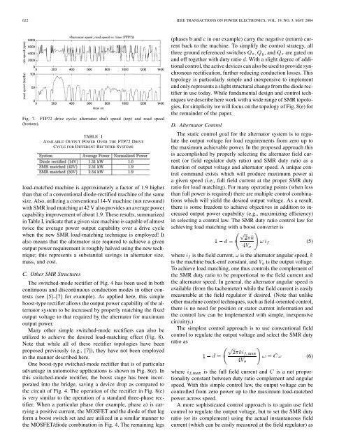
Fig. 7. FTP72 drive cycle: alternator shaft speed (top) <strong>and</strong> road speed<br />
(bottom).<br />
TABLE I<br />
AVAILABLE OUTPUT POWER OVER THE FTP72 DRIVE<br />
CYCLE FOR DIFFERENT RECTIFIER SYSTEMS<br />
load-matched machine is approximately a factor of 1.9 higher<br />
than that of a conventional diode-rectified machine of the same<br />
size. Also, utilizing a conventional 14-V machine (not rewound)<br />
with SMR load matching at 42 V also provides an average power<br />
capability improvement of about 1.9. These results, summarized<br />
in Table I, indicate that a given size machine is capable of almost<br />
twice the average power output capability over a drive cycle<br />
when the new SMR load-matching technique is employed! It<br />
also means that the alternator size required to achieve a given<br />
output power requirement is roughly halved using the new technique;<br />
this represents a substantial savings in alternator size,<br />
mass, <strong>and</strong> cost.<br />
C. Other SMR Structures<br />
The switched-mode rectifier of Fig. 4 has been used in both<br />
continuous <strong>and</strong> discontinuous conduction modes in other contexts<br />
(see [5]–[7] for example). As applied here, this simple<br />
boost-type rectifier allows the output power capability of the alternator<br />
system to be increased by properly matching the fixed<br />
output voltage to that required by the alternator for maximum<br />
output power.<br />
Many other simple switched-mode rectifiers can also be<br />
utilized to achieve the desired load-matching effect (Fig. 8).<br />
Note that while all of these rectifier topologies have been<br />
proposed previously (e.g., [7]), they have not been employed<br />
in the manner described here.<br />
One boost-type switched-mode rectifier that is of particular<br />
advantage in automotive applications is shown in Fig. 8(e). In<br />
this switched-mode rectifier, the boost stage has been incorporated<br />
into the bridge, saving a device drop as compared to<br />
the circuit of Fig. 4. The operation of the rectifier in Fig. 8(e)<br />
is very similar to the operation of a st<strong>and</strong>ard three-phase rectifier.<br />
When a particular phase (for example, phase a) is carrying<br />
a positive current, the MOSFET <strong>and</strong> the diode of that leg<br />
form a boost switch set <strong>and</strong> are utilized in a similar manner to<br />
the MOSFET/diode combination in Fig. 4. The remaining legs<br />
(phases b <strong>and</strong> c in our example) carry the negative (return) current<br />
back to the machine. To simplify the control strategy, all<br />
three ground referenced switches , <strong>and</strong> are gated on<br />
<strong>and</strong> off together with duty ratio . With a slight degree of additional<br />
control, the active devices can also be used to provide synchronous<br />
rectification, further reducing conduction losses. This<br />
topology is particularly simple <strong>and</strong> inexpensive to implement<br />
<strong>and</strong> only represents a slight structural change from the diode rectifier<br />
in use today. While fundamental design <strong>and</strong> control techniques<br />
we describe here work with a wide range of SMR topologies,<br />
for simplicity we will focus on the topology of Fig. 8(e) for<br />
the remainder of the paper.<br />
D. Alternator <strong>Control</strong><br />
The static control goal for the alternator system is to regulate<br />
the output voltage for load requirements from zero up to<br />
the maximum achievable power. In the proposed approach this<br />
is accomplished by properly selecting the alternator field current<br />
(or field regulator duty ratio) <strong>and</strong> SMR duty ratio as a<br />
function of output voltage <strong>and</strong> alternator speed. A unique control<br />
comm<strong>and</strong> exists which will produce maximum power at<br />
a given speed (i.e., full field current at the proper SMR duty<br />
ratio for load matching). For many operating points (when less<br />
than full power is required) there are multiple control combinations<br />
which will yield the desired output voltage. As a result,<br />
there is some freedom to achieve objectives in addition to increased<br />
output power capability (e.g., maximizing efficiency)<br />
in selecting a control law. The SMR duty ratio control law for<br />
achieving load matching with a boost converter is<br />
where is the field current, is the alternator angular speed,<br />
is the machine back-emf constant, <strong>and</strong> is the output voltage.<br />
To achieve load matching, one thus controls the complement of<br />
the SMR duty ratio to be proportional to the field current <strong>and</strong><br />
the alternator speed. In general, the alternator angular speed is<br />
available (from the tachometer) while the field current is easily<br />
measurable at the field regulator if desired. (Note that unlike<br />
other machine control techniques, such as field-oriented control,<br />
there is no need for position or stator current information <strong>and</strong><br />
the control law can be implemented with simple, inexpensive<br />
circuitry.)<br />
The simplest control approach is to use conventional field<br />
control to regulate the output voltage <strong>and</strong> select the SMR duty<br />
ratio as<br />
where is the full field current <strong>and</strong> is a net proportionality<br />
constant between duty ratio complement <strong>and</strong> angular<br />
speed. With this simple control law, the output voltage can be<br />
controlled from zero power up to the maximum load-matched<br />
power across speed.<br />
A more sophisticated control approach is to again use field<br />
control to regulate the output voltage, but to set the SMR duty<br />
ratio (or its complement) using the actual instantaneous field<br />
current (which can be easily measured at the field regulator) as<br />
(5)<br />
(6)