Automotive Power Generation and Control - IEEE Xplore
Automotive Power Generation and Control - IEEE Xplore
Automotive Power Generation and Control - IEEE Xplore

You also want an ePaper? Increase the reach of your titles
YUMPU automatically turns print PDFs into web optimized ePapers that Google loves.
624 <strong>IEEE</strong> TRANSACTIONS ON POWER ELECTRONICS, VOL. 19, NO. 3, MAY 2004<br />
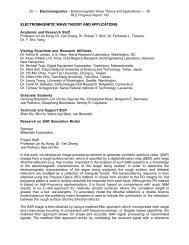
Fig. 9.<br />
Alternator with switched-mode rectifier <strong>and</strong> efficiency optimizing controller.<br />
amount necessary to support the output power or to reach the<br />
load-matched condition, whichever is lower. The duty ratio corresponding<br />
to the load-matched condition is set by on the<br />
controlled limiter <strong>and</strong> is derived from a speed sensor using the<br />
function (6). The fault protection controller can be implemented<br />
in a variety of ways to provide immunity from system<br />
transients. In its simplest form, it can be a crowbar <strong>and</strong> reset<br />
trigger on the devices. For example, in the event of a load-dump<br />
transient, the MOSFETs can be turned on <strong>and</strong> field field current<br />
turned off to force the phase currents to decay to zero.<br />
A variety of other control laws also exist. In general, the field<br />
current (or field regulator duty ratio) <strong>and</strong> SMR duty ratio are<br />
jointly selected as a function of output voltage <strong>and</strong> speed to regulate<br />
the output voltage, achieve high-power operation (when<br />
needed), <strong>and</strong> achieve other goals at partial load (such as maximizing<br />
efficiency). What all such controllers share is the regulation<br />
of the SMR for the load-matched condition when maximum<br />
output power is needed.<br />
IV. EXPERIMENTAL DEMONSTRATION OF LOAD MATCHING<br />
In this section, we provide experimental results of the load<br />
matching technique that support the analytical results presented<br />
in the earlier sections.<br />
A. Description of Experimental Setup<br />
The experimental setup consists of a st<strong>and</strong>ard Lundell automotive<br />
alternator (Ford 130 A) driven by a computer-controlled<br />
variable speed drive. Also included in the test st<strong>and</strong> is a dynamometer<br />
which is utilized to measure the mechanical power<br />
into the alternator. For the purposes of our experiments, the internal<br />
alternator field current regulator is disabled <strong>and</strong> a constant<br />
field current is supplied to the alternator by using an external<br />
power supply (<br />
A). The full-bridge three-phase rectifier<br />
that is a part of the original alternator assembly is disabled<br />
in order to connect the phases directly to the SMR. The alternator<br />
is loaded by the parallel combination of an electronic load<br />
(HP6050A) <strong>and</strong> a resistor bank. The electronic load is also utilized<br />
to set the output voltage level.<br />
The switched-mode rectifier used in the prototype system<br />
is of the topology illustrated in Fig. 8(e). The diodes are each<br />
implemented with an IXYS DSS2X41-01A Schottky diode<br />
module (comprising 2 paralleled diodes each nominally rated at<br />
40 A <strong>and</strong> 100 V). The active switches are IXYS IXFN230N10<br />
power MOSFETs (6 m nominal, 100 V). Tightly coupled<br />
across the output of the switched-mode rectifier (output<br />
to ground) are six paralleled ITW Paktron 106K100CS4<br />
multilayer polymer film capacitors (10 F, 100 V). These<br />
capacitors serve to suppress the high-frequency switching<br />
currents developed at the output of the boost rectifier. The