TMCC Track Power Controller 300/400 (TPC)Operating - Lionel
TMCC Track Power Controller 300/400 (TPC)Operating - Lionel
TMCC Track Power Controller 300/400 (TPC)Operating - Lionel

Create successful ePaper yourself
Turn your PDF publications into a flip-book with our unique Google optimized e-Paper software.
71-4189-250<br />
4/04<br />
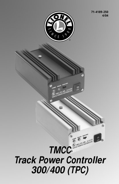
<strong>TMCC</strong><br />
<strong>Track</strong> <strong>Power</strong> <strong>Controller</strong><br />
<strong>300</strong>/<strong>400</strong> (<strong>TPC</strong>)
Congratulations<br />
Congratulations on your purchase of the <strong>TMCC</strong> <strong>Track</strong> <strong>Power</strong> <strong>Controller</strong> <strong>300</strong>/<strong>400</strong> (<strong>TPC</strong>)! The<br />
<strong>TPC</strong> <strong>300</strong> is capable of distributing up to <strong>300</strong> watts of power for solid state speed control<br />
while the <strong>TPC</strong> <strong>400</strong> brings a whopping <strong>400</strong> watts to your layout! Use the <strong>TPC</strong> with your<br />
Command Base (available separately, 6-12911) and your CAB-1 Remote <strong>Controller</strong> (available<br />
separately, 6-12868) to control any locomotive. Experience the superiority of the <strong>Lionel</strong><br />
TrainMaster Command Control system!<br />
Table of contents<br />
Wiring Your <strong>Track</strong> <strong>Power</strong> <strong>Controller</strong><br />
<strong>Power</strong>ing the <strong>Track</strong> <strong>Power</strong> <strong>Controller</strong> 3-6<br />
Connecting the <strong>TPC</strong> unit to the track 7<br />
Connecting the COMM wires 8<br />
Connecting additional <strong>TMCC</strong> products in a “daisy chain” 8<br />
Assigning the <strong>TPC</strong> unit’s ID# 9<br />
<strong>Operating</strong> the <strong>TPC</strong> Unit in the Command environment<br />
Setting the <strong>TPC</strong> to operate in the Command environment 10<br />
Turning track power ON in the Command environment 10<br />
Setting the maximum track voltage 11<br />
Turning track power OFF in the Command environment 11<br />
CAB-1 functions in the Command Control Environment 12<br />
<strong>Operating</strong> the <strong>TPC</strong> Unit in the conventional (non-Command) environment<br />
Setting the <strong>TPC</strong> to operate in the conventional environment 13<br />
CAB-1 Remote <strong>Controller</strong> functions 14-15<br />
Setting the stall voltage 16<br />
<strong>Operating</strong> QSI/M.T.H. Proto-Sound features with the <strong>TPC</strong> unit<br />
<strong>Power</strong>ing Up 17<br />
<strong>Operating</strong> QSI/M.T.H. Proto-Sound features with the <strong>TPC</strong> unit 17-18<br />
Programming your QSI/M.T.H. locomotive 19<br />
Specifications<br />
Physical 19<br />
Electrical Rating 19<br />
Limited Warranty/<strong>Lionel</strong> Service 20<br />
The following <strong>Lionel</strong> marks may be used throughout this instruction manual and are protected under<br />
law. All rights reserved.<br />
<strong>Lionel</strong> ® , TrainMaster ® , Odyssey ® , RailSounds ® , CrewTalk , TowerCom , DynaChuff ,<br />
StationSounds , Pullmor ® , ElectroCoupler , Magne-Traction ® , CAB-1 ® Remote <strong>Controller</strong>,<br />
<strong>Power</strong>Master ® , <strong>Lionel</strong> ZW ® , ZW ® , <strong>Power</strong>House ® , <strong>TMCC</strong> ® , <strong>Lionel</strong>ville , Lockon ® , Wireless Tether <br />
The name Fas<strong>Track</strong> ® is used with permission from Pitsco, Inc.<br />
M.T.H. ® , Proto-Sound ® , and Proto-Sound ® 2.0 are registered trademarks of M.T.H. Electric Trains ® .<br />
QSI ® is a registered trademark of QSIndustries, Inc.<br />
2
Wiring your <strong>Track</strong> <strong>Power</strong> <strong>Controller</strong><br />
<strong>Power</strong>ing the <strong>Track</strong> <strong>Power</strong> <strong>Controller</strong><br />
The power connections to the <strong>TPC</strong> unit are located on the back panel. These terminals are<br />
labeled HOT and NEUT under POWER IN. Your transformer or <strong>Power</strong>House <strong>Power</strong> Supply<br />
will power both the <strong>TPC</strong> unit and the track to which it is connected. Keep in mind that you<br />
may power the <strong>TPC</strong> unit with two transformers if they are phased correctly.<br />
Also, you may choose to power the <strong>TPC</strong> unit with two <strong>TMCC</strong> <strong>Power</strong>House <strong>Power</strong> Supplies,<br />
either the 135 watt version (available separately, 6-12866) or the 180 watt version (available<br />
separately, 6-22983). Be sure to purchase the <strong>TMCC</strong> <strong>TPC</strong> Cable Set (6-14194) to connect the<br />
<strong>TPC</strong> unit to the <strong>Power</strong>House <strong>Power</strong> Supply.<br />
Caution! Use at least 14-gauge wire when you are wiring the <strong>TPC</strong> unit to your<br />
transformer! Smaller wire gauges will not be able to handle the current.<br />
Wiring your <strong>TPC</strong> unit with a Transformer<br />
1. Attach one wire to the POWER/A terminal on the transformer and connect it to the HOT<br />
terminal on the <strong>TPC</strong> unit.<br />
2. Attach another wire to the COMMON/GROUND/U terminal on the transformer and connect<br />
it to the NEUT terminal on the <strong>TPC</strong> unit.<br />
POWER<br />
SUPPLY<br />
POWER/A<br />
COMMON/GROUND/U<br />
<strong>TPC</strong><br />
HOT<br />
NEUT<br />
COMM<br />
AUX- AUX+<br />
COM<br />
TRACK OUT POWER IN<br />
DAT A U NEUT HOT<br />
Figure 1. <strong>Power</strong>ing your <strong>TPC</strong> with a transformer<br />
3
Wiring your <strong>Track</strong> <strong>Power</strong> <strong>Controller</strong><br />
<strong>Power</strong>ing the <strong>Track</strong> <strong>Power</strong> <strong>Controller</strong> (continued)<br />
Wiring your <strong>TPC</strong> with two power supplies<br />
1. Plug the two single adapters into the double adapter. The adapters are sold separately in<br />
the <strong>TPC</strong> Cable Set (6-14194).<br />
2. Connect the black wires from the double adapter to the HOT terminal on the <strong>TPC</strong> unit.<br />
3. Connect the white wires from the double adapter to the NEUT terminal on the <strong>TPC</strong> unit.<br />
4. On your first power supply, connect one black wire to the <strong>Power</strong>/A terminal and the white<br />
wire to the Common/Ground/U terminal. Be sure that these wires are from the same single<br />
adapter.<br />
5. On your second power supply, connect one black wire to the <strong>Power</strong>/A terminal and the<br />
white wire to the Common/Ground/U terminal. Be sure that these wires are from the same<br />
single adapter.<br />
Note! Be sure to use two of the same power supplies. They must be set to the same output<br />
voltages.<br />
<strong>TPC</strong><br />
COMM<br />
AUX- AUX+<br />
COM<br />
TRACK OUT POWER IN<br />
DAT A U NEUT HOT<br />
Hot<br />
Neut<br />
<strong>Power</strong>/A<br />
Common/Ground/U<br />
<strong>Power</strong>/A<br />
Common/Ground/U<br />
POWER<br />
SUPPLY<br />
POWER<br />
SUPPLY<br />
Figure 2. <strong>Power</strong>ing the <strong>TPC</strong> with two transformers<br />
4
Wiring your <strong>Track</strong> <strong>Power</strong> <strong>Controller</strong><br />
<strong>Power</strong>ing the <strong>Track</strong> <strong>Power</strong> <strong>Controller</strong> (continued)<br />
Wiring the <strong>TPC</strong> unit with a single <strong>Power</strong>House <strong>Power</strong> Supply<br />
Note! To wire the <strong>TPC</strong> unit with a single <strong>Power</strong>House <strong>Power</strong> Supply, you will need to use<br />
the cables with the two adapters from the <strong>TMCC</strong> <strong>TPC</strong> Cable Set (available separately,<br />
6-14194).<br />
1. Plug the power output cable on the <strong>Power</strong>House <strong>Power</strong> Supply into the adapter on the<br />
<strong>TMCC</strong> <strong>TPC</strong> Cable.<br />
2. Attach the black wire to the HOT terminal on the <strong>TPC</strong> unit, located under the POWER IN<br />
label.<br />
3. Attach the white wire to the NEUT terminal on the <strong>TPC</strong> unit.<br />
<strong>TPC</strong><br />
COMM<br />
AUX- AUX+<br />
COM<br />
TRACK OUT POWER IN<br />
DAT A U NEUT HOT<br />
Hot<br />
Neut<br />
<strong>TMCC</strong> <strong>Power</strong>House<br />
<strong>Power</strong> Supply<br />
Figure 3. <strong>Power</strong>ing your <strong>TPC</strong> with a single <strong>Power</strong>House <strong>Power</strong> Supply<br />
5
Wiring your <strong>Track</strong> <strong>Power</strong> <strong>Controller</strong><br />
<strong>Power</strong>ing the <strong>Track</strong> <strong>Power</strong> <strong>Controller</strong> (continued)<br />
Note! Wiring the <strong>TPC</strong> unit with two <strong>Power</strong>House <strong>Power</strong> Supplies<br />
To wire the <strong>TPC</strong> unit with two <strong>Power</strong>House <strong>Power</strong> Supplies, you will need to use the cable with<br />
two adapters from the <strong>TMCC</strong> <strong>TPC</strong> Cable Set (available separately, 6-14194).<br />
1. Plug the power output cables on the <strong>Power</strong>House <strong>Power</strong> Supplies into the adapters on the<br />
<strong>TMCC</strong> <strong>TPC</strong> Cable.<br />
2. Attach the black wire to the HOT terminal on the <strong>TPC</strong> unit, located under the POWER IN<br />
label.<br />
3. Attach the white wire to the NEUT terminal on the <strong>TPC</strong> unit.<br />
Note! Wire similar <strong>Power</strong>House <strong>Power</strong> Supplies only. Do not wire a 135-watt <strong>Power</strong>House<br />
<strong>Power</strong> Supply with a 180-watt <strong>Power</strong>House <strong>Power</strong> Supply.<br />
<strong>TPC</strong><br />
NEUT<br />
HOT<br />
AUX- AUX+<br />
COMM<br />
COM<br />
TRACK OUT POWER IN<br />
DAT A U NEUT HOT<br />
1 2<br />
1<br />
2<br />
<strong>TMCC</strong> <strong>Power</strong>House<br />
<strong>Power</strong> Supplies<br />
Figure 4. <strong>Power</strong>ing your <strong>TPC</strong> with two <strong>Power</strong>House <strong>Power</strong> Supplies<br />
6
Wiring your <strong>Track</strong> <strong>Power</strong> <strong>Controller</strong><br />
Connecting the <strong>TPC</strong> unit to the track<br />
Use the terminals labeled TRACK OUT to connect the <strong>TPC</strong> unit to the track. If you are using<br />
<strong>Lionel</strong> O-27 or O gauge track, be sure to purchase a <strong>Lionel</strong> Lockon (6-62900). Follow<br />
these steps and refer to Figure 5 as you connect your <strong>TPC</strong> to the track.<br />
Caution! Use at least 14-gauge wire when you are wiring the <strong>TPC</strong> unit to the track!<br />
Smaller wire gauges will not be able to safely handle the current.<br />
1. Attach a <strong>Lionel</strong> Lockon (available separately, 6-62900) to the track.<br />
Slide the bottom edge of the outside rail into the metal lip on the Lockon. Press the clip at<br />
the end of the Lockon over the bottom edge of the inside rail.<br />
2. Attach one wire to the #1 spring clip terminal on the <strong>Lionel</strong> Lockon (or to the center rail)<br />
and connect it to the TRACK OUT terminal labeled A on the <strong>TPC</strong> unit.<br />
Spring clip terminal connections: Press down on the top of the terminal clip so that a<br />
metal loop is formed. Slide the bare end of the wire into the exposed loop. Release pressure<br />
on the terminal clip, allowing the crimped metal to pinch the end of the wire in the metal<br />
loop. Give a little tug on the wire to check if the hold is secure.<br />
3. Attach one wire to the #2 spring clip terminal on the <strong>Lionel</strong> Lockon (or to the outside rail)<br />
and connect it to the TRACK OUT terminal labeled U on the <strong>TPC</strong> unit.<br />
4. Attach one wire to the U terminal on the Command Base and connect it to the #2 Lockon<br />
terminal (or to the outside rail).<br />
<strong>TMCC</strong> <strong>Power</strong>House<br />
<strong>Power</strong> Supply<br />
<strong>TPC</strong><br />
TRACK OUT A<br />
TRACK OUT U<br />
GREEN<br />
RED<br />
COMMAND<br />
BASE<br />
U<br />
Figure 5. <strong>Track</strong> connections<br />
7
Wiring your <strong>Track</strong> <strong>Power</strong> <strong>Controller</strong><br />
Connecting the COMM wires<br />
Your <strong>TPC</strong> unit will need to communicate with the Command Base and any other <strong>TMCC</strong><br />
products you have connected to your <strong>TPC</strong> unit. To make these connections, you will need<br />
the Command Base Cable (available separately, 6-14191 for a 6’ cable and 6-14195 for a 20’<br />
cable). Follow these steps and refer to Figure 5 on page 7 to connect your <strong>TPC</strong> unit to the<br />
Command Base.<br />
Note! Your <strong>TPC</strong> is equipped with two additional COMM terminals, AX+ and AX-. They are<br />
intended for future capabilities. At this time, leave these terminals empty. Do not<br />
connect the DAT and COMM wires to AX+ and AX- terminals.<br />
1. Connect the DB9 Connector at the end of the Command Base Cable (the end that looks like<br />
a computer cable) to the COMPUTER terminal on the Command Base.<br />
2. Connect the red wire at the other end of the Command Base Cable to the DAT terminal on<br />
the <strong>TPC</strong> unit.<br />
3. Connect the green wire of the Command Base Cable to the COM terminal on the <strong>TPC</strong> unit.<br />
Connecting additional <strong>TMCC</strong> products in a “daisy chain”<br />
You may choose to power additional <strong>TMCC</strong> products using the same power supply and<br />
Command Base by creating a “daisy chain,” or a series of <strong>TMCC</strong> units wired in succession.<br />
To make these connections, we recommend that you purchase a <strong>Controller</strong> to <strong>Controller</strong> Cable,<br />
available separately in various lengths.<br />
COMM connections for additional units<br />
Attach a red wire to the DAT terminal of the <strong>TPC</strong> unit and connect it to the DAT terminal of<br />
the next <strong>TMCC</strong> product. Attach a green wire to the COM terminal of your <strong>TPC</strong> unit and connect<br />
it to the COM terminal of the next product. Add additional products in the same manner,<br />
connecting the DAT terminals and the COM terminals.<br />
Note! For maximum power output, each <strong>TPC</strong> should use its own power supply.<br />
8
Wiring your <strong>Track</strong> <strong>Power</strong> <strong>Controller</strong><br />
Assigning the <strong>TPC</strong> unit’s ID#<br />
To address and operate the <strong>TPC</strong> with your CAB-1 Remote <strong>Controller</strong>, you must assign an ID#<br />
to the <strong>TPC</strong> unit. The <strong>TPC</strong> unit can be assigned a TR (track/train) or an ENG (engine) ID#.<br />
Keep in mind that there are ten TR ID#’s (0-9) and 100 ENG ID#’s (0-99).<br />
1. Set the RUN/PRG switch to PRG on the <strong>TPC</strong>.<br />
Refer to Figure 6 for the location of the switch.<br />
2. Press TR or ENG on the CAB-1 Remote <strong>Controller</strong>.<br />
3. Enter the ID# of your choice (0-9 for TR ID#s or 0-99 for ENG ID#s) into the numeric<br />
keypad of the CAB-1 Remote <strong>Controller</strong>.<br />
4. Press SET on the CAB-1 Remote <strong>Controller</strong>.<br />
LED The COMM L.E.D. will flash for half of a second to indicate that the <strong>TPC</strong> has been set.<br />
5. Slide the switch back to RUN.<br />
At this point, the ID# of the <strong>TPC</strong> unit has been set.<br />
RUN/PRG Switch<br />
COMM TRACK RUN-PRG<br />
<strong>TMCC</strong> <strong>TPC</strong> <strong>400</strong> 6-14179<br />
TRACK POWER CONTROLLER<br />
20A<br />
Figure 6. Switch location<br />
9
<strong>Operating</strong> the <strong>TPC</strong> Unit in the Command environment<br />
Operate your <strong>TPC</strong> unit in Command mode when your locomotives are equipped with<br />
TrainMaster Command Control. In the Command Control environment, the locomotives<br />
receive signals from the Command Base that tell the locomotive what to do. Because speed and<br />
direction are not controlled by track voltage, use the <strong>TPC</strong> to set the maximum power that will<br />
be supplied at all times.<br />
Setting the <strong>TPC</strong> to operate in the Command environment<br />
Before you use the <strong>TPC</strong> unit in the Command environment, you must set the <strong>TPC</strong> unit to<br />
Command mode.<br />
1. Press TR or ENG on the CAB-1 Remote <strong>Controller</strong>.<br />
2. Enter the ID# of the <strong>TPC</strong> unit into the numeric keypad on the CAB-1 Remote <strong>Controller</strong>.<br />
3. Press the L button on the bottom of the CAB-1 Remote <strong>Controller</strong>.<br />
LED The TRACK L.E.D. will flash slowly to indicate that the <strong>TPC</strong> is in Command mode.<br />
When power is supplied to the track, the TRACK L.E.D. will blink quickly.<br />
4. Press the SET button on the CAB-1 Remote <strong>Controller</strong> to save this mode.<br />
LED The COMM L.E.D. will long blink to indicate that the <strong>TPC</strong> has been set.<br />
The <strong>TPC</strong> will remain in Command mode, even after the power is turned off.<br />
Note! The <strong>TPC</strong> will turn OFF when changing between conventional and Command<br />
operations.<br />
Turning track power ON in the Command environment<br />
You must use your CAB-1 Remote <strong>Controller</strong> to turn track power ON with the <strong>TPC</strong> unit.<br />
1. Press the TR or ENG button on the CAB-1 Remote <strong>Controller</strong>.<br />
2. Enter the ID# of the <strong>TPC</strong> unit into the numeric keypad on the CAB-1 Remote <strong>Controller</strong>.<br />
3. Press the BOOST button on the CAB-1 Remote <strong>Controller</strong>.<br />
LED The TRACK L.E.D. will blink quickly to indicate that the track is powered up.<br />
At this point, full track voltage is applied to the track.<br />
10
<strong>Operating</strong> the <strong>TPC</strong> Unit in the Command environment<br />
Setting the maximum track voltage<br />
While track voltage is not used to control the speed of your locomotives in Command<br />
Control, you may choose to adjust the track voltage to adjust the maximum power available to<br />
your locomotives.<br />
1. Address the <strong>TPC</strong>. Press the TR or ENG button on the CAB-1 Remote <strong>Controller</strong>, then enter<br />
the ID# of the <strong>TPC</strong>.<br />
2. Adjust the track voltage. Use the RED KNOB on the CAB-1 Remote <strong>Controller</strong> to increase<br />
the track voltage with a clockwise turn; decrease track voltage with a counter-clockwise<br />
turn.<br />
3. With the <strong>TPC</strong> unit’s RUN/PROG switch set to RUN, press SET on the CAB-1 Remote<br />
<strong>Controller</strong>. You have set the default voltage. Each time the <strong>TPC</strong> is powered up, the track<br />
voltage will be set to this level.<br />
To restore the track voltage to the default (full power), simply press AUX1, AUX2, then 0.<br />
You may also turn the RED KNOB to restore power.<br />
Turning track power OFF in the Command environment<br />
You must use your CAB-1 Remote <strong>Controller</strong> to turn track power OFF with the <strong>TPC</strong> unit.<br />
1. Press the TR or ENG button on the CAB-1 Remote <strong>Controller</strong>.<br />
2. Enter the ID# of the <strong>TPC</strong> unit into the numeric keypad on the CAB-1 Remote <strong>Controller</strong>.<br />
3. Press the AUX1 button on the CAB-1 Remote <strong>Controller</strong>.<br />
4. Enter 0 into the numeric keypad on the CAB-1 Remote <strong>Controller</strong>.<br />
LED The TRACK L.E.D. will blink slowly to indicate that track power is OFF.<br />
At this point, track power is shut off.<br />
11
<strong>Operating</strong> the <strong>TPC</strong> Unit in the Command environment<br />
CAB-1 Remote <strong>Controller</strong> functions in the Command Control<br />
environment<br />
Use the following CAB-1Remote <strong>Controller</strong> commands in the Command Control<br />
environment.<br />
Adjusts track voltage level.<br />
Turns track power ON. Use AUX1, 0 command to<br />
turn track power OFF.<br />
L<br />
Places the <strong>TPC</strong> in Command mode with power OFF.<br />
M<br />
Places the <strong>TPC</strong> in conventional mode with power OFF.<br />
Turns off track power.<br />
L<br />
M<br />
H<br />
Sets the number of throttle increments<br />
to 80 speed steps. Coarse resolution in<br />
intervals of speed.<br />
Sets the number of throttle increments<br />
to 200 speed steps. Medium resolution<br />
in intervals of speed.<br />
Sets the number of throttle increments<br />
to <strong>400</strong> speed steps. Fine resolution in<br />
intervals of speed.<br />
SET L M H<br />
Saves current track voltage and speed resolution as power-up<br />
defaults when the RUN/PRG switch is set to RUN. Assigns the <strong>TPC</strong><br />
ID# when the RUN/PRG switch is set to PRG.<br />
Resets the <strong>TPC</strong> to factory defaults.<br />
12
<strong>Operating</strong> the <strong>TPC</strong> Unit in the conventional<br />
(non-Command) environment<br />
Operate your <strong>TPC</strong> unit in conventional mode when your locomotive is not equipped with<br />
TrainMaster Command Control. Conventional locomotives operate by varying the voltage<br />
to the track. For example, a conventional locomotive will increase in speed as track voltage<br />
increases. The <strong>TPC</strong> unit will allow you to operate your conventional locomotives by remote<br />
control, varying the voltage supplied to the track.<br />
Note! All conventional locomotives on the same loop or block of track will be controlled<br />
together.<br />
LED The TRACK L.E.D. will increase in intensity as track voltage increases. If it blinks, you<br />
are not in conventional mode. See below.<br />
Setting the <strong>TPC</strong> to operate in the conventional environment<br />
Before you use the <strong>TPC</strong> unit in the conventional (non-Command) environment, you must<br />
set the <strong>TPC</strong> unit to conventional mode.<br />
1. Press TR or ENG on the CAB-1 Remote <strong>Controller</strong>.<br />
2. Enter the ID# of the <strong>TPC</strong> unit into the numeric keypad on the CAB-1 Remote <strong>Controller</strong>.<br />
3. Press the M button on the bottom of the CAB-1 Remote <strong>Controller</strong>.<br />
LED The TRACK L.E.D. will turn OFF to indicate that the <strong>TPC</strong> is in conventional mode<br />
without power.<br />
4. Press the SET button on the CAB-1 Remote <strong>Controller</strong>.<br />
LED The COMM L.E.D. will long blink to indicate that the <strong>TPC</strong> has been set.<br />
The <strong>TPC</strong> will remain in conventional mode, even after the power is turned off.<br />
Note!<br />
The <strong>TPC</strong> will turn OFF when changing modes.<br />
13
<strong>Operating</strong> the <strong>TPC</strong> Unit in the conventional<br />
(non-Command) environment<br />
CAB-1 Remote <strong>Controller</strong> functions<br />
Use the following CAB-1 Remote <strong>Controller</strong> commands to control your locomotive in<br />
conventional mode.<br />
Turn clockwise to increase the speed of the<br />
locomotive; turn counter-clockwise to decrease<br />
the speed.<br />
Press and hold to increase the speed of the<br />
locomotive; release to return speed to the initial<br />
setting plus one step. Tap BOOST to increase one step<br />
for fine control.<br />
Press and hold to decrease the speed of the<br />
locomotive; release to return speed to the initial<br />
setting minus one step. Tap BRAKE to decrease one<br />
step for fine control.<br />
Sounds the whistle or horn on the locomotive.<br />
Activates the bell.<br />
Controls the direction of the train. Removes track<br />
power when pressed; restores track power when<br />
released.<br />
Activates the numeric keypad.<br />
Acts like the shift key on your computer. Allows the<br />
buttons to have another function.<br />
Opens the front coupler (M.T.H. ® Proto-Sound ® 2.0<br />
engines).<br />
L<br />
M<br />
H<br />
Opens the rear coupler (M.T.H. ® Proto-Sound ® 2.0<br />
engines).<br />
Saves current settings to be restored upon next<br />
power-up when the RUN/PRG switch is set to RUN.<br />
Assigns the <strong>TPC</strong> ID# when the RUN/PRG switch is set<br />
to PRG.<br />
Sets <strong>TPC</strong> to Command mode with power OFF.<br />
Sets the <strong>TPC</strong> to conventional operation with power<br />
OFF.<br />
Sets the maximum speed limit in conventional mode.<br />
Use the red knob to set the throttle at your desired<br />
maximum speed, then press H.<br />
14<br />
SET L M H
<strong>Operating</strong> the <strong>TPC</strong> Unit in the conventional<br />
(non-Command) environment<br />
CAB-1 Remote <strong>Controller</strong> functions (continued)<br />
Turns track power off.<br />
Sets the stall (minimum) voltage.<br />
Places track voltage to the current<br />
stall voltage (set with AUX1, 1).<br />
L<br />
Sets the number of throttle increments to 80 speed steps.<br />
M<br />
Sets the number of throttle increments to 200 speed steps.<br />
H<br />
Sets the number of throttle increments to <strong>400</strong> speed steps.<br />
Resets the <strong>TPC</strong> to factory defaults.<br />
15
<strong>Operating</strong> the <strong>TPC</strong> Unit in the conventional<br />
(non-Command) environment<br />
Setting the stall voltage<br />
You can set the <strong>TPC</strong> stall voltage with your CAB-1 Remote <strong>Controller</strong>. Setting the stall<br />
voltage locks the minimum voltage. Once set, you will not be able to lower the voltage any<br />
lower than this level. This is especially useful when operating locomotives with E-units.<br />
Because you can set the minimum voltage, you can prevent the E-unit from resetting itself due<br />
to a complete loss of power.<br />
To completely remove the voltage from the track, press the AUX1, 0 on the CAB-1<br />
Note!<br />
Remote <strong>Controller</strong>.<br />
1. Use the RED KNOB on the CAB-1 Remote <strong>Controller</strong> to increase the voltage to your desired<br />
minimum voltage.<br />
2. Press AUX1, 1 on the numeric keypad when you have reached the desired minimum<br />
voltage.<br />
3. Press SET if you wish to save the minimum voltage for the next time you power up the <strong>TPC</strong>.<br />
LED The COMM L.E.D. will long blink to indicate that the <strong>TPC</strong> has been set.<br />
To reset the stall voltage back to zero, press the AUX1, AUX2, 0 on the CAB-1<br />
Note!<br />
Remote <strong>Controller</strong>. This will reset ALL conventional settings. If you wish to save the<br />
settings, press the SET button on the CAB-1 Remote <strong>Controller</strong>.<br />
Press AUX1, 4 to set the track voltage to the current stall voltage.<br />
Note!<br />
This is a quick way to turn down the voltage to the current stall setting.<br />
16
<strong>Operating</strong> QSI ® /M.T.H. ® Proto-Sound ® features<br />
with the <strong>TPC</strong> unit<br />
Additional features have been added to the <strong>TPC</strong> unit to unlock the operation of the<br />
QSI ® /M.T.H. ® E units. The <strong>TPC</strong> unit makes M.T.H. ® products operating in conventional<br />
mode compatible with the <strong>Lionel</strong> TrainMaster Command Control system!<br />
<strong>Power</strong>ing up<br />
Use your CAB-1 Remote <strong>Controller</strong> to power up the the track and control an M.T.H. ®<br />
Proto-Sound ® 1.0 locomotive.<br />
1. Press TR or ENG on the CAB-1 Remote <strong>Controller</strong>.<br />
2. Enter the ID# of the <strong>TPC</strong> unit into the numeric keypad on the CAB-1 Remote <strong>Controller</strong>.<br />
3. Press AUX1, 9 on the CAB-1 Remote <strong>Controller</strong>.<br />
The power up sequence has been activated.<br />
Caution!<br />
Do not press the DIR button; full power is applied to the track at this point.<br />
4. After the engine sounds begin (or five seconds), enter the track voltage setting. Press 8 to<br />
supply 30% of full power.<br />
Note!<br />
If you do not enter this number, your locomotive will take off as soon as you press<br />
the DIR button on the CAB-1 Remote <strong>Controller</strong>! If you accidentally start up the<br />
locomotive without selecting a voltage level (step 4), simply turn the power off and<br />
restart using this sequence.<br />
5. Move ‘em out! Press the DIR button on the CAB-1 Remote <strong>Controller</strong>.<br />
<strong>Operating</strong> M.T.H. ® Proto-Sound ® features with the <strong>TPC</strong> unit<br />
The <strong>TPC</strong> allows you to operate M.T.H. ® Proto-Sound ® 2.0 locomotives in conventional<br />
mode. At the press of a few buttons, your favorite conventional Proto-Sound ® 2.0<br />
features—like speed control and coupler operation—are at your command.<br />
Note!<br />
All M.T.H. ® Proto-Sound ® 2.0 features can be accessed in conventional<br />
mode. Refer to the next section for additional information.<br />
17
<strong>Operating</strong> QSI ® /M.T.H. ® Proto-Sound ® features<br />
with the <strong>TPC</strong> unit<br />
<strong>Operating</strong> M.T.H. ® Proto-Sound ® features with the <strong>TPC</strong> unit (continued)<br />
Turns track power off.<br />
(used with Proto-Sound ® 1.0 and 2.0)<br />
M.T.H. ® Sets the minimum voltage.<br />
(used with Proto-Sound ® 1.0)<br />
M.T.H. ® Station Talk.<br />
(used with Proto-Sound ® 2.0)<br />
M.T.H. ® Fast Horn.<br />
(used with Proto-Sound ® 2.0)<br />
Places track voltage to the current stall voltage<br />
(set with AUX1, 1). (used with all)<br />
M.T.H. ® Programming Pulse.<br />
(used with Proto-Sound ® 1.0)<br />
M.T.H. ® Fast Bell.<br />
(used with Proto-Sound ® 2.0)<br />
Places track voltage at 30% of input.<br />
(used with Proto-Sound ® 1.0)<br />
Places full voltage on the track. Start up<br />
sequence for M.T.H. ® Proto-Sound ® 1.0.<br />
Resets the <strong>TPC</strong> to factory<br />
defaults.<br />
M.T.H. ® Speed control toggle ON/OFF.<br />
(used with Proto-Sound ® 2.0)<br />
SET L M H<br />
M.T.H. ® Reset to factory defaults.<br />
(used with Proto-Sound ® 2.0)<br />
L<br />
M.T.H. ® Lock direction toggle ON/OFF.<br />
(used with Proto-Sound ® 2.0)<br />
Sets the number of throttle<br />
increments to 80 speed steps.<br />
M<br />
Sets the number of throttle<br />
increments to 200 speed steps.<br />
H<br />
Sets the number of throttle<br />
increments to <strong>400</strong> speed steps.<br />
M.T.H. ® Opens front coupler.<br />
(used with Proto-Sound ® 2.0)<br />
M.T.H. ® Opens rear coupler.<br />
(used with Proto-Sound ® 2.0)<br />
Saves current track voltage and speed resolution as power-up defaults when the RUN/PRG<br />
switch is set to RUN. Assigns the <strong>TPC</strong> ID# when the RUN/PRG switch is set to PRG.<br />
18
<strong>Operating</strong> QSI ® /M.T.H. ® Proto-Sound ® features<br />
with the <strong>TPC</strong> unit<br />
Programming your QSI ® /M.T.H. ® locomotive<br />
The <strong>TPC</strong> allows you to program your QSI ® /M.T.H. ® locomotives with ease, bringing some of<br />
the Proto-Sound ® features under your control while operating in conventional mode.<br />
Follow these steps and refer to your locomotive’s instructions for information about your<br />
engine’s features.<br />
1. Press M on the CAB-1 Remote <strong>Controller</strong>. Be sure to wait for the sounds to stop completely<br />
This will reset the engine by completely removing power.<br />
2. Press AUX1, 9 on the CAB-1 Remote <strong>Controller</strong>.<br />
<strong>Track</strong> voltage goes to full.<br />
3. Press 5 repeatedly on the numeric keypad until the desired feature is activated.<br />
A programming pulse is sent through the track to program the QSI ® /M.T.H. ® units.<br />
Note! Do not press the AUX1 button on your CAB-1 Remote <strong>Controller</strong> between pressing<br />
9 and 5.<br />
4. Press the WHISTLE button on the CAB-1 Remote <strong>Controller</strong> to program that feature.<br />
Consult your M.T.H. ® engine operating instructions for specific details.<br />
Specifications<br />
Physical<br />
Size: 6.125” x 3.75” x 2.7”<br />
Electrical Ratings<br />
Maximum input voltage: 9 to 30 volts (AC) at 50 or 60 Hz<br />
COMM input signal: +/- 12 volts<br />
Maximum output current: 15 amps at 20 volts or <strong>300</strong> watts (<strong>TPC</strong> <strong>300</strong>)<br />
20 amps at 20 volts or <strong>400</strong> watts (<strong>TPC</strong> <strong>400</strong>)<br />
19
Limited Warranty/<strong>Lionel</strong> Service<br />
This <strong>Lionel</strong> product, including all mechanical and electrical components, moving parts, motors and<br />
structural components, except for light bulbs, is warranted to the original consumer-purchaser, for one<br />
year against original defects in materials or workmanship when purchased through an authorized <strong>Lionel</strong><br />
merchant.<br />
This warranty does NOT cover normal wear and tear, light bulbs, defects appearing in the course of<br />
commercial use, or damage resulting from abuse or misuse of the product by the purchaser. Transfer of this<br />
product by the original consumer-purchaser to another person voids this warranty. Modification of this product<br />
voids this warranty.<br />
Any warranted product which is defective in original materials or workmanship and is delivered by the<br />
original consumer-purchaser to <strong>Lionel</strong> L.L.C. or an authorized <strong>Lionel</strong> L.L.C. Service Center, together with proof of<br />
original purchase will, at the option of <strong>Lionel</strong> L.L.C., be repaired or replaced, without charge for parts or labor.<br />
In the event the defective product cannot be repaired, and a replacement is not available, a refund of the original<br />
purchase price will be granted. Any products on which warranty service is sought must be sent freight or postage<br />
prepaid, as transportation and shipping charges are not covered by the warranty.<br />
In no event shall <strong>Lionel</strong> L.L.C. be liable for incidental or consequential damages.<br />
Some states do not allow the exclusion or limitation of incidental or consequential damages, so the above<br />
exclusion may not apply to you.<br />
This limited warranty gives you specific legal rights, and you may have other rights which vary from state<br />
to state.<br />
Instructions for Obtaining Service<br />
If service for this <strong>Lionel</strong> L.L.C. product is required, bring the item, along with your dated sales receipt and<br />
completed warranty information to the nearest Authorized <strong>Lionel</strong> Service Center. Your nearest <strong>Lionel</strong> Service<br />
Center can be found by calling 1-800-4-<strong>Lionel</strong>, or by accessing our Website at www.lionel.com.<br />
If you prefer to send your product back to <strong>Lionel</strong> L.L.C. for repair in Michigan, you must first call<br />
586-949-4100 or FAX 586-949-5429, or write to Customer Service, P.O. Box 748, New Baltimore, MI 48047-<br />
0748, stating what the item is, when it was purchased and what seems to be the problem. You will be sent a<br />
return authorization letter and label to ensure your merchandise will be properly handled upon receipt.<br />
Once you have received your return authorization and label, make sure that the item is packed to prevent<br />
damage during shipping and handling. We suggest that you use the product’s original packaging. This<br />
shipment must be prepaid and we recommend that it be insured.<br />
Please make sure you have followed all of the above instructions carefully before returning any<br />
merchandise for service. You may choose to have your product repaired by one of our Authorized <strong>Lionel</strong> Service<br />
Centers after its warranty has expired. A reasonable service fee will be charged.<br />
Warranty Information<br />
Please complete the information below and keep it, along with your dated sales receipt. You must present<br />
this and your dated sales receipt when requesting warranty service.<br />
Name ________________________________________________________________________<br />
Address<br />
______________________________________________________________________<br />
Place of Purchase ________________________________________________________________<br />
Date of Purchase<br />
Product Number<br />
________________________________________________________________<br />
________________________________________________________________<br />
Product Description<br />
______________________________________________________________<br />
©2004 LIONEL L.L.C., CHESTERFIELD, MI 48051-2493<br />
UNITED STATES OF AMERICA<br />
PRINTED IN CHINA