Druckschrift 9981.0190, Broadcast Antenna Systems - Romkatel
Druckschrift 9981.0190, Broadcast Antenna Systems - Romkatel
Druckschrift 9981.0190, Broadcast Antenna Systems - Romkatel

Create successful ePaper yourself
Turn your PDF publications into a flip-book with our unique Google optimized e-Paper software.
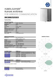
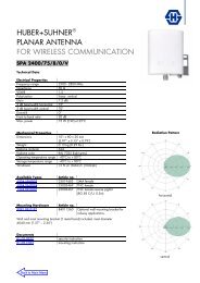
TV Transmitting <strong>Antenna</strong><br />
with dipole panels K 52 30 5. . or K 52 31 5. .<br />
174 – 230 MHz<br />
● Typical antenna array with dipole panels K 52 30 57 or K 52 31 57.<br />
● The feeder network is made up of coaxial power splitters and flexible connecting cables<br />
in accordance with the radiation patterns specification and the transmitting power.<br />
Input<br />
Frequency range<br />
VSWR<br />
Impedance<br />
Polarization<br />
Internal connections<br />
Max. power<br />
Radiation pattern<br />
Half antenna splitting<br />
Pressurization<br />
Grounding<br />
Max. wind velocity<br />
Connectors according to IEC, EIA or DIN.<br />
174 – 230 MHz<br />
< 1.05 in the operating channel after tuning<br />
or < 1.1 in the whole range<br />
50 Ω<br />
Horizontal or vertical<br />
Connectors according to IEC, EIA or DIN<br />
are used throughout the system,<br />
allowing easy assembly and maintenance.<br />
According to customer’s requirements.<br />
The examples of radiation patterns are valid<br />
for horizontal polarization.<br />
At vertical polarization patterns vary slightly.<br />
Upon request, the antenna can be divided into<br />
2 halves (for measurement and maintenance).<br />
The 2 halves are connected by a<br />
2-way power splitter or patch panel.<br />
Splitters and connecting cables can be supplied<br />
with dry air (please specify when ordering).<br />
Via mounting parts.<br />
225 km/h / 200 km/h<br />
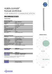
H<br />
1600 mm<br />
K 52 30 5. . Material: Hot-dip galvanized steel<br />
No. Panels Gain* Weight <strong>Antenna</strong> Windload<br />
of per (at mid-band) (without mounting height H (v = 160 km/h)<br />
bays bay dB times hardware) kg m kN<br />
2 5.5 3.5 66 1.1<br />
1 3 4.3 2.7 94 1.3 1.85<br />
4 3.1 2.0 122 2.2<br />
2 8.5 7.1 122 2.2<br />
2 3 7.3 5.4 173 2.9 3.7<br />
4 6.1 4.1 224 4.4<br />
K 52 31 57<br />
2 11.5 14.1 224 4.4<br />
4 3 10.3 10.7 346 6.1 7.4<br />
4 9.1 8.1 453 8.8<br />
K 52 31 5. . Material: Weather-proof aluminum<br />
No. Panels Gain* Weight <strong>Antenna</strong> Windload<br />
of per (at mid-band) (without mounting height H (v = 160 km/h)<br />
bays bay dB times hardware) kg m kN<br />
2 5.5 3.5 22 0.8<br />
1 3 3.4 2.2 29 1.2 1.2<br />
4 2.0 1.6 36 1.6<br />
2 8.5 7.1 44 1.6<br />
2 3 6.4 4.4 58 2.8 2.4<br />
4 5.0 3.2 72 3.2<br />
2 11.5 14.1 88 3.2<br />
4 3 9.4 8.7 116 6.0 4.8<br />
4 8.0 6.3 144 6.4<br />
* Referred to λ/2 dipole. Attenuation of the internal cabling and the gain-decrease<br />
in case of null fill in the vertical radiation pattern are not considered.<br />
Approximate values for gain decrease:<br />
cable attenuation: 0.2 – 0.4 dB<br />
null fill:<br />
0.2 – 0.5 dB<br />
Gain figures are valid for the direction of maximum radiation (see diagrams on<br />
following page).<br />
32