Druckschrift 9981.0190, Broadcast Antenna Systems - Romkatel
Druckschrift 9981.0190, Broadcast Antenna Systems - Romkatel
Druckschrift 9981.0190, Broadcast Antenna Systems - Romkatel

You also want an ePaper? Increase the reach of your titles
YUMPU automatically turns print PDFs into web optimized ePapers that Google loves.
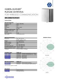
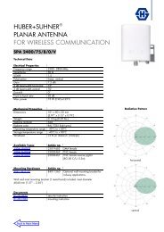
TV Transmitting <strong>Antenna</strong><br />
with panels K 72 31 4. . or K 73 31 4. .<br />
470 – 860 MHz<br />
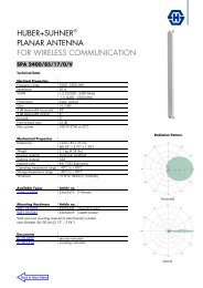
● Typical antenna array with dipole panels K 72 31 4. .<br />
Input<br />
Frequency range<br />
VSWR<br />
Impedance<br />
Polarization<br />
Max. power<br />
Radiation pattern<br />
Half antenna splitting<br />
Pressurization<br />
Painting<br />
Grounding<br />
Max. wind velocity<br />
Connectors according to IEC, EIA or DIN.<br />
470 – 860 MHz<br />
< 1.05 in the operating channel after tuning<br />
or < 1.1 in the whole frequency range<br />
50 Ω<br />
Horizontal or vertical<br />
1 kW, higher power on request.<br />
The examples of radiation patterns are valid<br />
for horizontal polarization.<br />
At vertical polarization patterns vary slightly.<br />
Upon request, the antenna can be divided into<br />
2 halves (for measurement and maintenance).<br />
The 2 halves are connected by a<br />
2-way power splitter or patch panel.<br />
Splitters and connecting cables can be supplied<br />
with dry air (please specify when ordering).<br />
If required, the antenna is painted in aviation<br />
warning colours.<br />
Via mounting parts.<br />
225 km/h<br />
H<br />
1150 mm<br />
Top view<br />
No. Panels Gain* Weight <strong>Antenna</strong> Windload**<br />
of per (at mid-band) (without mounting height H (v = 160 km/h)<br />
bays bay dB times hardware) kg m kN<br />
2 9.2 8.3 31 1.1<br />
1 3 7.6 5.8 45 1.15 1.7<br />
4 6.3 4.3 59 2.5<br />
2 12.2 16.6 59 2.2<br />
2 3 10.6 11.5 86 2.15 3.4<br />
4 9.3 8.5 116 5.0<br />
2 15.2 33.1 116 4.4<br />
4 3 13.6 22.9 172 4.45 6.8<br />
4 12.3 17.0 228 10.0<br />
* Referred to λ/2 dipole. Attenuation of the internal cabling and the gain-decrease<br />
in case of null fill in the vertical radiation pattern are not considered.<br />
Approximate values for gain decrease:<br />
cable attenuation: 0.2 – 0.4 dB<br />
null fill:<br />
0.2 – 0.5 dB<br />
Gain figures are valid for the direction of maximum radiation (see diagrams on<br />
following page).<br />
** Average values, depending on design and arrangement.<br />
10<br />
3<br />
0<br />
dB<br />
Horizontal Radiation Pattern<br />
of the antenna arrangement<br />
see above<br />
42