internal cooling for the blow molding industry - Blow Moulding Controls
internal cooling for the blow molding industry - Blow Moulding Controls
internal cooling for the blow molding industry - Blow Moulding Controls

You also want an ePaper? Increase the reach of your titles
YUMPU automatically turns print PDFs into web optimized ePapers that Google loves.
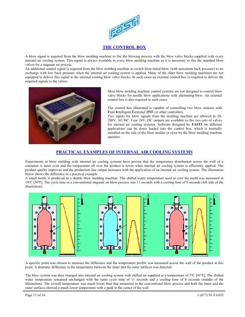
THE CONTROL BOX<br />
A <strong>blow</strong> signal is required from <strong>the</strong> <strong>blow</strong> <strong>molding</strong> machine to fire <strong>the</strong> <strong>blow</strong>ing process with <strong>the</strong> <strong>blow</strong> valve blocks supplied with every<br />
<strong>internal</strong> air <strong>cooling</strong> system. This signal is always available in every <strong>blow</strong> <strong>molding</strong> machine as it is necessary to fire <strong>the</strong> standard <strong>blow</strong><br />
valves <strong>for</strong> a stagnant air process.<br />
An additional control signal is required from <strong>the</strong> <strong>blow</strong> <strong>molding</strong> machine to switch from initial <strong>blow</strong> (with maximum back pressure) to air<br />
exchange with low back pressure when <strong>the</strong> <strong>internal</strong> air <strong>cooling</strong> system is applied. Many of <strong>the</strong> older <strong>blow</strong> <strong>molding</strong> machines are not<br />
equipped to deliver this signal to <strong>the</strong> <strong>internal</strong> <strong>cooling</strong> <strong>blow</strong> valve blocks. In such cases an external control box is required to deliver <strong>the</strong><br />
required signals to <strong>the</strong> valves.<br />
Most <strong>blow</strong> <strong>molding</strong> machine control systems are not designed to control <strong>blow</strong><br />
valve blocks <strong>for</strong> needle <strong>blow</strong> applications with alternating <strong>blow</strong>. An external<br />
control box is also required in such cases.<br />
The control box illustrated is capable of controlling two <strong>blow</strong> stations with<br />
Fasti Intelligent Terminal (FIT) or o<strong>the</strong>r controllers.<br />
Two inputs <strong>for</strong> <strong>blow</strong> signals from <strong>the</strong> <strong>molding</strong> machine are allowed in 20-<br />
280V, AC/DC. Four 24V, DC outputs are available to fire two sets of valves<br />
<strong>for</strong> <strong>internal</strong> air <strong>cooling</strong> systems. Software designed by FASTI <strong>for</strong> different<br />
applications can be down loaded into <strong>the</strong> control box, which is normally<br />
installed on <strong>the</strong> side of <strong>the</strong> <strong>blow</strong> molder or close by <strong>the</strong> <strong>blow</strong> <strong>molding</strong> machine<br />
operator.<br />
PRACTICAL EXAMPLES OF INTERNAL AIR COOLING SYSTEMS<br />
Experiments in <strong>blow</strong> <strong>molding</strong> with <strong>internal</strong> air <strong>cooling</strong> systems have proven that <strong>the</strong> temperature distribution across <strong>the</strong> wall of a<br />
container is more even and <strong>the</strong> temperature all over <strong>the</strong> product is lower when <strong>internal</strong> air <strong>cooling</strong> system is efficiently applied. The<br />
product quality improves and <strong>the</strong> production line output increases with <strong>the</strong> application of an <strong>internal</strong> air <strong>cooling</strong> system. The illustration<br />
below shows <strong>the</strong> difference in a practical example.<br />
A small bottle is produced in a shuttle <strong>blow</strong> <strong>molding</strong> machine. The chilled water temperature used to cool <strong>the</strong> mold was measured at<br />
10ºC [50ºF]. The cycle time in a conventional stagnant air <strong>blow</strong> process was 11 seconds with a <strong>cooling</strong> time of 8 seconds (left side of <strong>the</strong><br />
illustration).<br />
A specific point was chosen to measure <strong>the</strong> difference and <strong>the</strong> temperature profile was measured across <strong>the</strong> wall of <strong>the</strong> product at this<br />
point. A dramatic difference in <strong>the</strong> temperature between <strong>the</strong> inner and <strong>the</strong> outer surfaces was detected.<br />
The <strong>blow</strong> system was <strong>the</strong>n changed into <strong>internal</strong> air <strong>cooling</strong> system with chilled air supplied at a temperature of 5ºC [41ºF]. The chilled<br />
water temperature remained unchanged with <strong>the</strong> same cycle time of 11 seconds and a <strong>cooling</strong> time of 8 seconds (middle of <strong>the</strong><br />
illustration). The overall temperature was much lower than that measured in <strong>the</strong> conventional <strong>blow</strong> process and both <strong>the</strong> inner and <strong>the</strong><br />
outer surfaces showed a much lower temperature with a peak in <strong>the</strong> center of <strong>the</strong> wall.<br />
Page 11 of 14<br />
1 (877) 91-FASTI