IPv4 Addressing and Subnetting - Router Alley
IPv4 Addressing and Subnetting - Router Alley
IPv4 Addressing and Subnetting - Router Alley

Create successful ePaper yourself
Turn your PDF publications into a flip-book with our unique Google optimized e-Paper software.
<strong>IPv4</strong> <strong>Addressing</strong> <strong>and</strong> <strong>Subnetting</strong> v1.41 – Aaron Balchunas<br />
1<br />
Hardware <strong>Addressing</strong><br />
- <strong>IPv4</strong> <strong>Addressing</strong> <strong>and</strong> <strong>Subnetting</strong> -<br />
A hardware address is used to uniquely identify a host within a local<br />
network. Hardware addressing is a function of the Data-Link layer of the<br />
OSI model (Layer-2).<br />
Ethernet utilizes the 48-bit MAC address as its hardware address. The<br />
MAC address is often hardcoded on physical network interfaces, though<br />
some interfaces support changing the MAC address using special utilities. In<br />
virtualization environments, dynamically assigning MAC addresses is very<br />
common.<br />
A MAC address is most often represented in hexadecimal, using one of two<br />
accepted formats:<br />
00:43:AB:F2:32:13<br />
0043.ABF2.3213<br />
The first six hexadecimal digits of a MAC address identify the manufacturer<br />
of the physical network interface. This is referred to as the OUI<br />
(Organizational Unique Identifier). The last six digits uniquely identify<br />
the host itself, <strong>and</strong> are referred to as the host ID.<br />
The MAC address has one shortcoming – it contains no hierarchy. MAC<br />
addresses provide no mechanism to create boundaries between networks.<br />
There is no method to distinguish one network from another.<br />
This lack of hierarchy poses significant difficulties to network scalability. If<br />
only Layer-2 hardware addressing existed, all hosts would technically exist<br />
on the same network. Internetworks like the Internet could not exist, as it<br />
would be impossible to separate my network from your network.<br />
Imagine if the entire Internet existed purely as a single Layer-2 switched<br />
network. Switches, as a rule, will forward a broadcast out every port. With<br />
billions of hosts on the Internet, the resulting broadcast storms would be<br />
devastating. The Internet would simply collapse.<br />
The scalability limitations of Layer-2 hardware addresses are mitigated<br />
using logical addresses, covered in great detail in this guide.<br />
* * *<br />
All original material copyright © 2013 by Aaron Balchunas (aaron@routeralley.com),<br />
unless otherwise noted. All other material copyright © of their respective owners.<br />
This material may be copied <strong>and</strong> used freely, but may not be altered or sold without the expressed written<br />
consent of the owner of the above copyright. Updated material may be found at http://www.routeralley.com.
<strong>IPv4</strong> <strong>Addressing</strong> <strong>and</strong> <strong>Subnetting</strong> v1.41 – Aaron Balchunas<br />
2<br />
Logical <strong>Addressing</strong><br />
Logical addressing is a function of the Network layer of the OSI Model<br />
(Layer-3), <strong>and</strong> provides a hierarchical structure to separate networks.<br />
Logical addresses are never hardcoded on physical network interfaces, <strong>and</strong><br />
can be dynamically assigned <strong>and</strong> changed freely.<br />
A logical address contains two components:<br />
• Network ID – identifies which network a host belongs to.<br />
• Host ID – uniquely identifies the host on that network.<br />
Examples of logical addressing protocols include Internetwork Packet<br />
Exchange (IPX) <strong>and</strong> Internet Protocol (IP). IPX was predominantly used<br />
on Novell networks, but is now almost entirely deprecated. IP is the most<br />
widely-used logical address, <strong>and</strong> is the backbone protocol of the Internet.<br />
Internet Protocol (IP)<br />
In the 1970’s, the Department of Defense developed the Transmission<br />
Control Protocol (TCP), to provide both Network <strong>and</strong> Transport layer<br />
functions. When this proved to be an inflexible solution, those functions<br />
were separated - with the Internet Protocol (IP) providing Network layer<br />
services, <strong>and</strong> TCP providing Transport layer services.<br />
Together, TCP <strong>and</strong> IP provide the core functionality for the TCP/IP or<br />
Internet protocol suite.<br />
IP provides two fundamental Network layer services:<br />
• Logical addressing – provides a unique address that identifies both<br />
the host, <strong>and</strong> the network that host exists on.<br />
• Routing – determines the best path to a particular destination<br />
network, <strong>and</strong> then routes data accordingly.<br />
IP was originally defined in RFC 760, <strong>and</strong> has been revised several times.<br />
IP Version 4 (<strong>IPv4</strong>) was the first version to experience widespread<br />
deployment, <strong>and</strong> is defined in RFC 791. <strong>IPv4</strong> will be the focus of this guide.<br />
<strong>IPv4</strong> employs a 32-bit address, which limits the number of possible<br />
addresses to 4,294,967,296. <strong>IPv4</strong> will eventually be replaced by IP Version 6<br />
(IPv6), due to a shortage of available <strong>IPv4</strong> addresses. IPv6 is covered in<br />
great detail in another guide.<br />
* * *<br />
All original material copyright © 2013 by Aaron Balchunas (aaron@routeralley.com),<br />
unless otherwise noted. All other material copyright © of their respective owners.<br />
This material may be copied <strong>and</strong> used freely, but may not be altered or sold without the expressed written<br />
consent of the owner of the above copyright. Updated material may be found at http://www.routeralley.com.
<strong>IPv4</strong> <strong>Addressing</strong> <strong>and</strong> <strong>Subnetting</strong> v1.41 – Aaron Balchunas<br />
3<br />
<strong>IPv4</strong> <strong>Addressing</strong><br />
A core function of IP is to provide logical addressing for hosts. An IP<br />
address provides a hierarchical structure to both uniquely identify a host,<br />
<strong>and</strong> what network that host exists on.<br />
An IP address is most often represented in decimal, in the following format:<br />
158.80.164.3<br />
An IP address is comprised of four octets, separated by periods:<br />
First Octet Second Octet Third Octet Fourth Octet<br />
158 80 164 3<br />
Each octet is an 8-bit number, resulting in a 32-bit IP address. The smallest<br />
possible value of an octet is 0, or 00000000 in binary. The largest possible<br />
value of an octet is 255, or 11111111 in binary.<br />
The above IP address represented in binary would look as follows:<br />
First Octet Second Octet Third Octet Fourth Octet<br />
10011110 01010000 10100100 00000011<br />
Decimal to Binary Conversion<br />
The simplest method of converting between decimal <strong>and</strong> binary is to<br />
remember the following table:<br />
128 64 32 16 8 4 2 1<br />
To convert a decimal number of 172 to binary, start with the leftmost<br />
column. Since 172 is greater than 128, that binary bit will be set to 1. Next,<br />
add the value of the next column (128 + 64 = 192). Since 172 is less than<br />
192, that binary bit will be set to 0.<br />
Again, add the value of the next column (128 + 32 = 160). Since 172 is<br />
greater than 160, that binary bit will be set to 1. Continue this process until<br />
the columns with binary bits set to 1 add up to 172:<br />
Decimal 128 64 32 16 8 4 2 1<br />
Binary 1 0 1 0 1 1 0 0<br />
* * *<br />
All original material copyright © 2013 by Aaron Balchunas (aaron@routeralley.com),<br />
unless otherwise noted. All other material copyright © of their respective owners.<br />
This material may be copied <strong>and</strong> used freely, but may not be altered or sold without the expressed written<br />
consent of the owner of the above copyright. Updated material may be found at http://www.routeralley.com.
<strong>IPv4</strong> <strong>Addressing</strong> <strong>and</strong> <strong>Subnetting</strong> v1.41 – Aaron Balchunas<br />
4<br />
Binary to Decimal Conversion<br />
Converting from binary back to decimal is even simpler. Apply the binary<br />
number to the conversion table, <strong>and</strong> then add up any columns with binary<br />
bits set to 1.<br />
For example, consider the binary number of 11110001:<br />
Decimal 128 64 32 16 8 4 2 1<br />
Binary 1 1 1 1 0 0 0 1<br />
By adding 128 + 64 + 32 + 16+ 1, it can be determined that 11110001<br />
equals 241.<br />
The Subnet Mask<br />
Part of an IP address identifies the network. The other part of the address<br />
identifies the host. A subnet mask is required to provide this distinction:<br />
158.80.164.3 255.255.0.0<br />
The above IP address has a subnet mask of 255.255.0.0. The subnet mask<br />
follows two rules:<br />
• If a binary bit is set to a 1 (or on) in a subnet mask, the corresponding<br />
bit in the address identifies the network.<br />
• If a binary bit is set to a 0 (or off) in a subnet mask, the corresponding<br />
bit in the address identifies the host.<br />
Looking at the above address <strong>and</strong> subnet mask in binary:<br />
IP Address: 10011110.01010000.10100100.00000011<br />
Subnet Mask: 11111111.11111111.00000000.00000000<br />
The first 16 bits of the subnet mask are set to 1. Thus, the first 16 bits of the<br />
address (158.80) identify the network. The last 16 bits of the subnet mask are<br />
set to 0. Thus, the last 16 bits of the address (164.3) identify the unique host<br />
on that network.<br />
The network portion of the subnet mask must be contiguous. For example, a<br />
subnet mask of 255.0.0.255 is not valid.<br />
* * *<br />
All original material copyright © 2013 by Aaron Balchunas (aaron@routeralley.com),<br />
unless otherwise noted. All other material copyright © of their respective owners.<br />
This material may be copied <strong>and</strong> used freely, but may not be altered or sold without the expressed written<br />
consent of the owner of the above copyright. Updated material may be found at http://www.routeralley.com.
<strong>IPv4</strong> <strong>Addressing</strong> <strong>and</strong> <strong>Subnetting</strong> v1.41 – Aaron Balchunas<br />
5<br />
The Subnet Mask (continued)<br />
Hosts on the same logical network will have identical network addresses,<br />
<strong>and</strong> can communicate freely. For example, the following two hosts are on<br />
the same network:<br />
Host A: 158.80.164.100 255.255.0.0<br />
Host B: 158.80.164.101 255.255.0.0<br />
Both share the same network address (158.80), which is determined by the<br />
255.255.0.0 subnet mask. Hosts that are on different networks cannot<br />
communicate without an intermediating device. For example:<br />
Host A: 158.80.164.100 255.255.0.0<br />
Host B: 158.85.164.101 255.255.0.0<br />
The subnet mask has remained the same, but the network addresses are now<br />
different (158.80 <strong>and</strong> 158.85 respectively). Thus, the two hosts are not on<br />
the same network, <strong>and</strong> cannot communicate without a router between them.<br />
Routing is the process of forwarding packets from one network to another.<br />
Consider the following, trickier example:<br />
Host A: 158.80.1.1 255.248.0.0<br />
Host B: 158.79.1.1 255.248.0.0<br />
The specified subnet mask is now 255.248.0.0, which doesn’t fall cleanly on<br />
an octet boundary. To determine if these hosts are on separate networks, first<br />
convert everything to binary:<br />
Host A Address: 10011110.01010000.00000001.00000001<br />
Host B Address: 10011110.01001111.00000001.00000001<br />
Subnet Mask: 11111111.11111000.00000000.00000000<br />
Remember, the 1 (or on) bits in the subnet mask identify the network portion<br />
of the address. In this example, the first 13 bits (the 8 bits of the first octet,<br />
<strong>and</strong> the first 5 bits of the second octet) identify the network. Looking at only<br />
the first 13 bits of each address:<br />
Host A Address: 10011110.01010<br />
Host B Address: 10011110.01001<br />
Clearly, the network addresses are not identical. Thus, these two hosts are on<br />
separate networks, <strong>and</strong> require a router to communicate.<br />
* * *<br />
All original material copyright © 2013 by Aaron Balchunas (aaron@routeralley.com),<br />
unless otherwise noted. All other material copyright © of their respective owners.<br />
This material may be copied <strong>and</strong> used freely, but may not be altered or sold without the expressed written<br />
consent of the owner of the above copyright. Updated material may be found at http://www.routeralley.com.
<strong>IPv4</strong> <strong>Addressing</strong> <strong>and</strong> <strong>Subnetting</strong> v1.41 – Aaron Balchunas<br />
6<br />
IP Address Classes<br />
The <strong>IPv4</strong> address space has been structured into several classes. The value<br />
of the first octet of an address determines the class of the network:<br />
Class First Octet Range Default Subnet Mask<br />
Class A 1 - 127 255.0.0.0<br />
Class B 128 - 191 255.255.0.0<br />
Class C 192 - 223 255.255.255.0<br />
Class D 224 - 239 -<br />
Class A networks range from 1 to 127. The default subnet mask is 255.0.0.0.<br />
Thus, by default, the first octet defines the network, <strong>and</strong> the last three octets<br />
define the host. This results in a maximum of 127 Class A networks, with<br />
16,777,214 hosts per network!<br />
Example of a Class A address:<br />
Address: 64.32.254.100<br />
Subnet Mask: 255.0.0.0<br />
Class B networks range from 128 to 191. The default subnet mask is<br />
255.255.0.0. Thus, by default, the first two octets define the network, <strong>and</strong> the<br />
last two octets define the host. This results in a maximum of 16,384 Class B<br />
networks, with 65,534 hosts per network.<br />
Example of a Class B address:<br />
Address: 152.41.12.195<br />
Subnet Mask: 255.255.0.0<br />
Class C networks range from 192 to 223. The default subnet mask is<br />
255.255.255.0. Thus, by default, the first three octets define the network,<br />
<strong>and</strong> the last octet defines the host. This results in a maximum of 2,097,152<br />
Class C networks, with 254 hosts per network.<br />
Example of a Class C address:<br />
Address: 207.79.233.6<br />
Subnet Mask: 255.255.255.0<br />
Class D networks are reserved for multicast traffic. Class D addresses do<br />
not use a subnet mask.<br />
* * *<br />
All original material copyright © 2013 by Aaron Balchunas (aaron@routeralley.com),<br />
unless otherwise noted. All other material copyright © of their respective owners.<br />
This material may be copied <strong>and</strong> used freely, but may not be altered or sold without the expressed written<br />
consent of the owner of the above copyright. Updated material may be found at http://www.routeralley.com.
<strong>IPv4</strong> <strong>Addressing</strong> <strong>and</strong> <strong>Subnetting</strong> v1.41 – Aaron Balchunas<br />
7<br />
CIDR (Classless Inter-Domain Routing)<br />
Classless Inter-Domain Routing (CIDR) is a simplified method of<br />
representing a subnet mask. CIDR identifies the number of binary bits set to<br />
a 1 (or on) in a subnet mask, preceded by a slash.<br />
For example, a subnet mask of 255.255.255.240 would be represented as<br />
follows in binary:<br />
11111111.11111111.11111111.11110000<br />
The first 28 bits of the above subnet mask are set to 1. The CIDR notation<br />
for this subnet mask would thus be /28.<br />
The CIDR mask is often appended to the IP address. For example, an IP<br />
address of 192.168.1.1 <strong>and</strong> a subnet mask of 255.255.255.0 would be<br />
represented as follows using CIDR notation:<br />
192.168.1.1 /24<br />
Address Classes vs. Subnet Mask<br />
Remember the following three rules:<br />
• The first octet on an address dictates the class of that address.<br />
• The subnet mask determines what part of an address identifies the<br />
network, <strong>and</strong> what part identifies the host.<br />
• Each class has a default subnet mask. A network using its default<br />
subnet mask is referred to as a classful network.<br />
For example, 10.1.1.1 is a Class A address, <strong>and</strong> its default subnet mask is<br />
255.0.0.0 (/8 in CIDR).<br />
It is entirely possible to use subnet masks other than the default. For<br />
example, a Class B subnet mask can be applied to a Class A address:<br />
10.1.1.1 /16<br />
However, this does not change the class of the above address. It remains a<br />
Class A address, which has been subnetted using a Class B mask.<br />
Remember, the only thing that determines the class of an IP address is the<br />
first octet of that address. Likewise, the subnet mask is the only thing that<br />
determines what part of an address identifies the network, <strong>and</strong> what part<br />
identifies the host.<br />
* * *<br />
All original material copyright © 2013 by Aaron Balchunas (aaron@routeralley.com),<br />
unless otherwise noted. All other material copyright © of their respective owners.<br />
This material may be copied <strong>and</strong> used freely, but may not be altered or sold without the expressed written<br />
consent of the owner of the above copyright. Updated material may be found at http://www.routeralley.com.
<strong>IPv4</strong> <strong>Addressing</strong> <strong>and</strong> <strong>Subnetting</strong> v1.41 – Aaron Balchunas<br />
8<br />
Subnet <strong>and</strong> Broadcast Addresses<br />
On each IP network, two host addresses are reserved for special use:<br />
• The subnet (or network) address<br />
• The broadcast address<br />
Neither of these addresses can be assigned to an actual host.<br />
The subnet address is used to identify the network itself. A routing table<br />
contains a list of known networks, <strong>and</strong> each network is identified by its<br />
subnet address. Subnet addresses contain all 0 bits in the host portion of<br />
the address.<br />
For example, 192.168.1.0/24 is a subnet address. This can be determined by<br />
looking at the address <strong>and</strong> subnet mask in binary:<br />
IP Address: 11000000.10101000.00000001.00000000<br />
Subnet Mask: 11111111.11111111.11111111.00000000<br />
Note that all host bits in the address are set to 0.<br />
The broadcast address identifies all hosts on a particular network. A packet<br />
sent to the broadcast address will be received <strong>and</strong> processed by every host on<br />
that network. Broadcast addresses contain all 1 bits in the host portion of<br />
the address.<br />
For example, 192.168.1.255/24 is a broadcast address. Note that all host bits<br />
are set to 1:<br />
IP Address: 11000000.10101000.00000001.11111111<br />
Subnet Mask: 11111111.11111111.11111111.00000000<br />
Broadcasts are one of three types of IP packets:<br />
• Unicasts are packets sent from one host to one other host<br />
• Multicasts are packets sent from one host to a group of hosts<br />
• Broadcasts are packets sent from one host to all other hosts on the<br />
local network<br />
A router, by default, will never forward a multicast or broadcast packet<br />
from one interface to another.<br />
A switch, by default, will forward a multicast or broadcast packet out every<br />
port, except for the port that originated the multicast or broadcast.<br />
* * *<br />
All original material copyright © 2013 by Aaron Balchunas (aaron@routeralley.com),<br />
unless otherwise noted. All other material copyright © of their respective owners.<br />
This material may be copied <strong>and</strong> used freely, but may not be altered or sold without the expressed written<br />
consent of the owner of the above copyright. Updated material may be found at http://www.routeralley.com.
<strong>IPv4</strong> <strong>Addressing</strong> <strong>and</strong> <strong>Subnetting</strong> v1.41 – Aaron Balchunas<br />
9<br />
<strong>Subnetting</strong><br />
<strong>Subnetting</strong> is the process of creating new networks (or subnets) by stealing<br />
bits from the host portion of a subnet mask. There is one caveat: stealing bits<br />
from hosts creates more networks but fewer hosts per network.<br />
Consider the following Class C network:<br />
192.168.254.0<br />
The default subnet mask for this network is 255.255.255.0. This single<br />
network can be segmented, or subnetted, into multiple networks. For<br />
example, assume a minimum of 10 new networks are required. Resolving<br />
this is possible using the following magical formula:<br />
2 n<br />
The exponent ‘n’ identifies the number of bits to steal from the host portion<br />
of the subnet mask. The default Class C mask (255.255.255.0) looks as<br />
follows in binary:<br />
11111111.1111111.1111111.00000000<br />
There are a total of 24 bits set to 1, which are used to identify the network.<br />
There are a total of 8 bits set to 0, which are used to identify the host, <strong>and</strong><br />
these host bits can be stolen.<br />
Stealing bits essentially involves changing host bits (set to 0 or off) in the<br />
subnet mask to network bits (set to 1 or on). Remember, network bits in a<br />
subnet mask must always be contiguous - skipping bits is not allowed.<br />
Consider the result if three bits are stolen. Using the above formula:<br />
2 n = 2 3 = 8 = 8 new networks created<br />
However, a total of 8 new networks does not meet the original requirement<br />
of at least 10 networks. Consider the result if four bits are stolen:<br />
2 n = 2 4 = 16 = 16 new networks created<br />
A total of 16 new networks does meet the original requirement. Stealing four<br />
host bits results in the following new subnet mask:<br />
11111111.11111111.11111111.11110000 = 255.255.255.240<br />
* * *<br />
All original material copyright © 2013 by Aaron Balchunas (aaron@routeralley.com),<br />
unless otherwise noted. All other material copyright © of their respective owners.<br />
This material may be copied <strong>and</strong> used freely, but may not be altered or sold without the expressed written<br />
consent of the owner of the above copyright. Updated material may be found at http://www.routeralley.com.
<strong>IPv4</strong> <strong>Addressing</strong> <strong>and</strong> <strong>Subnetting</strong> v1.41 – Aaron Balchunas<br />
10<br />
<strong>Subnetting</strong> (continued)<br />
In the previous example, a Class C network was subnetted to create 16 new<br />
networks, using a subnet mask of 255.255.255.240 (or /28 in CIDR). Four<br />
bits were stolen in the subnet mask, leaving only four bits for hosts.<br />
To determine the number of hosts this results in, for each of the new 16<br />
networks, a slightly modified formula is required:<br />
2 n – 2<br />
Consider the result if four bits are available for hosts:<br />
2 n – 2 = 2 4 – 2 = 16 – 2 = 14 usable hosts per network<br />
Thus, subnetting a Class C network with a /28 mask creates 16 new<br />
networks, with 14 usable hosts per network.<br />
Why is the formula for calculating usable hosts 2 n – 2? Because it is never<br />
possible to assign a host an address with all 0 or all 1 bits in the host portion<br />
of the address. These are reserved for the subnet <strong>and</strong> broadcast addresses,<br />
respectively. Thus, every time a network is subnetted, useable host addresses<br />
are lost.<br />
The 2 n -2 Rule <strong>and</strong> Subnetted Networks<br />
To avoid confusion, it was historically unacceptable to use the first <strong>and</strong> last<br />
new networks created when subnetting, as it is possible for a classful<br />
network to have the same subnet <strong>and</strong> broadcast address as its subnetted<br />
networks. This required the 2 n – 2 formula to also be used when calculating<br />
the number of new networks created while subnetting.<br />
However, this is no longer a restriction for modern equipment <strong>and</strong> routing<br />
protocols. Specifically, on Cisco IOS devices, the following comm<strong>and</strong> is<br />
now enabled by default:<br />
<strong>Router</strong>(config)# ip subnet-zero<br />
The ip subnet-zero comm<strong>and</strong>s allows for the use of networks with all 0 or all<br />
1 bits in the stolen network portion of the address. Thus, the formula for<br />
calculating the number of new networks created is simply 2 n .<br />
Remember though, the formula for calculating usable hosts is always 2 n – 2.<br />
(Reference: http://www.cisco.com/en/US/tech/tk648/tk361/technologies_tech_note09186a0080093f18.shtml)<br />
* * *<br />
All original material copyright © 2013 by Aaron Balchunas (aaron@routeralley.com),<br />
unless otherwise noted. All other material copyright © of their respective owners.<br />
This material may be copied <strong>and</strong> used freely, but may not be altered or sold without the expressed written<br />
consent of the owner of the above copyright. Updated material may be found at http://www.routeralley.com.
<strong>IPv4</strong> <strong>Addressing</strong> <strong>and</strong> <strong>Subnetting</strong> v1.41 – Aaron Balchunas<br />
11<br />
Determining the Range of Subnetted Networks<br />
Determining the range of the newly created networks can be accomplished<br />
using several methods. The long method involves some binary magic.<br />
Consider the example 192.168.254.0 network again, which was subnetted<br />
using a 255.255.255.240 mask:<br />
192.168.254.0: 11000000.10101000.11111110.00000000<br />
255.255.255.240: 11111111.11111111.11111111.11110000<br />
<strong>Subnetting</strong> stole four bits in the fourth octet, creating a total of 16 new<br />
networks. Looking at only the fourth octet, the first newly created network is<br />
0000. The second new network is 0001. Calculating all possible<br />
permutations of the four stolen bits:<br />
Binary Decimal Binary Decimal Binary Decimal<br />
.0000 xxxx .0 .0110 xxxx .96 .1100 xxxx .192<br />
.0001 xxxx .16 .0111 xxxx .112 .1101 xxxx .208<br />
.0010 xxxx .32 .1000 xxxx .128 .1110 xxxx .224<br />
.0011 xxxx .48 .1001 xxxx .144 .1111 xxxx .240<br />
.0100 xxxx .64 .1010 xxxx .160<br />
.0101 xxxx .80 .1011 xxxx .176<br />
Note that this equates to exactly 16 new networks. The decimal value<br />
represents the first (or the subnet) address of each newly created network. To<br />
determine the range for the hosts of the first new network:<br />
Binary Decimal Binary Decimal Binary Decimal<br />
.0000 0000 .0 .0000 0110 .6 .0000 1100 .12<br />
.0000 0001 .1 .0000 0111 .7 .0000 1101 .13<br />
.0000 0010 .2 .0000 1000 .8 .0000 1110 .14<br />
.0000 0011 .3 .0000 1001 .9 .0000 1111 .15<br />
.0000 0100 .4 .0000 1010 .10<br />
.0000 0101 .5 .0000 1011 .11<br />
The binary value has been split to emphasize the separation of the stolen<br />
network bits from the host bits. The first address has all 0 bits in the host<br />
portion (0000), <strong>and</strong> is the subnet address for this network. The last address<br />
has all 1 bits in the host portion, <strong>and</strong> thus is the broadcast address for this<br />
network. Note that there are exactly 14 usable addresses to assign to hosts.<br />
* * *<br />
All original material copyright © 2013 by Aaron Balchunas (aaron@routeralley.com),<br />
unless otherwise noted. All other material copyright © of their respective owners.<br />
This material may be copied <strong>and</strong> used freely, but may not be altered or sold without the expressed written<br />
consent of the owner of the above copyright. Updated material may be found at http://www.routeralley.com.
<strong>IPv4</strong> <strong>Addressing</strong> <strong>and</strong> <strong>Subnetting</strong> v1.41 – Aaron Balchunas<br />
12<br />
Determining the Range of Subnetted Networks (continued)<br />
Calculating the ranges of subnetted networks can quickly become tedious<br />
when using the long binary method. The shortcut method involves taking the<br />
subnet mask (255.255.255.240 from the previous example), <strong>and</strong> subtracting<br />
the subnetted octet (240) from 256.<br />
256 – 240 = 16<br />
Assuming ip subnet-zero is enabled, the first network will begin at 0. Then,<br />
simply continue adding 16 to identify the first address of each new network:<br />
0 16 32 48 64 80 96 112 128 144 160 176 192 208 224 240<br />
Knowing the first address of each new network makes it simple to determine<br />
the last address of each network:<br />
First address of network 0 16 32 48 64 80 96 112 128 144<br />
Last address of network 15 31 47 63 79 95 111 127 143 159<br />
Only the first 10 networks were calculated, for brevity. The first address of<br />
each network becomes the subnet address for that network. The last address<br />
of each network becomes the broadcast address for that network.<br />
Once the first <strong>and</strong> last address of each network is known, determining the<br />
usable range for hosts is straightforward:<br />
Subnet address 0 16 32 48 64 80 96 112 128 144<br />
Usable Range<br />
1<br />
14<br />
17<br />
30<br />
33<br />
46<br />
Broadcast address 15 31 47 63 79 95 111 127 143 159<br />
Hosts on the same network (such as 192.168.254.2 <strong>and</strong> 192.168.254.14) can<br />
communicate freely.<br />
49<br />
62<br />
65<br />
78<br />
81<br />
94<br />
97<br />
110<br />
113<br />
126<br />
Hosts on different networks (such as 192.168.254.61 <strong>and</strong> 192.168.254.66)<br />
require a router to communicate.<br />
129<br />
142<br />
145<br />
158<br />
* * *<br />
All original material copyright © 2013 by Aaron Balchunas (aaron@routeralley.com),<br />
unless otherwise noted. All other material copyright © of their respective owners.<br />
This material may be copied <strong>and</strong> used freely, but may not be altered or sold without the expressed written<br />
consent of the owner of the above copyright. Updated material may be found at http://www.routeralley.com.
<strong>IPv4</strong> <strong>Addressing</strong> <strong>and</strong> <strong>Subnetting</strong> v1.41 – Aaron Balchunas<br />
13<br />
Class A <strong>Subnetting</strong> Example<br />
Consider the following subnetted Class A network: 10.0.0.0 255.255.248.0<br />
Now consider the following questions:<br />
• How many new networks were created?<br />
• How many usable hosts are there per network?<br />
• What is the full range of the first three networks?<br />
By default, the 10.0.0.0 network has a subnet mask of 255.0.0.0. To<br />
determine the number of bits stolen:<br />
255.0.0.0: 11111111.00000000.00000000.00000000<br />
255.255.248.0: 11111111.11111111.11111000.00000000<br />
Clearly, 13 bits have been stolen to create the new subnet mask. To calculate<br />
the total number of new networks:<br />
2 n = 2 13 = 8192 new networks created<br />
There are clearly 11 bits remaining in the host portion of the mask:<br />
2 n – 2 = 2 11 – 2 = 2048 – 2 = 2046 usable hosts per network<br />
Calculating the ranges is a bit tricky. Using the shortcut method, subtract the<br />
third octet (248) of the subnet mask (255.255.248.0) from 256.<br />
256 – 248 = 8<br />
The first network will begin at 0, again. However, the ranges are spread<br />
across multiple octets. The ranges of the first three networks look as follows:<br />
Subnet address 10.0.0.0 10.0.8.0 10.0.16.0<br />
Usable Range<br />
10.0.0.1<br />
10.0.7.254<br />
10.0.8.1<br />
10.0.15.254<br />
10.0.16.1<br />
10.0.23.254<br />
Broadcast address 10.0.7.255 10.0.15.255 10.0.23.255<br />
* * *<br />
All original material copyright © 2013 by Aaron Balchunas (aaron@routeralley.com),<br />
unless otherwise noted. All other material copyright © of their respective owners.<br />
This material may be copied <strong>and</strong> used freely, but may not be altered or sold without the expressed written<br />
consent of the owner of the above copyright. Updated material may be found at http://www.routeralley.com.
<strong>IPv4</strong> <strong>Addressing</strong> <strong>and</strong> <strong>Subnetting</strong> v1.41 – Aaron Balchunas<br />
14<br />
Private vs. Public <strong>IPv4</strong> Addresses<br />
The rapid growth of the Internet resulted in a shortage of available <strong>IPv4</strong><br />
addresses. In response, a specific subset of the <strong>IPv4</strong> address space was<br />
designated as private, to temporarily alleviate this problem.<br />
A public address can be routed on the Internet. Thus, hosts that must be<br />
Internet-accessible must be configured with (or reachable by) public<br />
addresses. Allocation of public addresses is governed by the Internet<br />
Assigned Numbers Authority (IANA).<br />
A private address is intended for internal use within a home or<br />
organization, <strong>and</strong> can be freely used by anyone. However, private addresses<br />
can never be routed on the Internet. In fact, Internet routers are configured to<br />
immediately drop traffic with private addresses.<br />
Three private address ranges were defined in RFC 1918, one for each <strong>IPv4</strong><br />
class:<br />
• Class A - 10.x.x.x /8<br />
• Class B - 172.16.x.x /12<br />
• Class C - 192.168.x.x /24<br />
It is possible to translate between private <strong>and</strong> public addresses, using<br />
Network Address Translation (NAT). NAT allows a host configured with<br />
a private address to be stamped with a public address, thus allowing that host<br />
to communicate across the Internet. It is also possible to translate multiple<br />
privately-addressed hosts to a single public address, which conserves the<br />
public address space.<br />
NAT provides an additional benefit – hiding the specific addresses <strong>and</strong><br />
addressing structure of the internal (or private) network.<br />
Note: NAT is not restricted to private-to-public address translation, though<br />
that is the most common application. NAT can also perform public-to-public<br />
address translation, as well as private-to-private address translation.<br />
NAT is only a temporarily solution to the address shortage problem. <strong>IPv4</strong><br />
will eventually be replaced with IPv6, which supports a vast address space.<br />
Both NAT <strong>and</strong> IPv6 are covered extensively in other guides.<br />
* * *<br />
All original material copyright © 2013 by Aaron Balchunas (aaron@routeralley.com),<br />
unless otherwise noted. All other material copyright © of their respective owners.<br />
This material may be copied <strong>and</strong> used freely, but may not be altered or sold without the expressed written<br />
consent of the owner of the above copyright. Updated material may be found at http://www.routeralley.com.
<strong>IPv4</strong> <strong>Addressing</strong> <strong>and</strong> <strong>Subnetting</strong> v1.41 – Aaron Balchunas<br />
15<br />
Reserved <strong>IPv4</strong> Addresses<br />
In addition to the three private <strong>IPv4</strong> ranges, several other addresses <strong>and</strong><br />
ranges are reserved for specific purposes:<br />
• The 0.0.0.0 /0 network is used to identify all networks, <strong>and</strong> is referred<br />
to as the default route. If a default route exists in a routing table, it<br />
will be used only if there is not a more specific route to a particular<br />
destination. Routing <strong>and</strong> default routes are covered extensively in<br />
another guide.<br />
• The 0.0.0.0 /8 range is used to identify hosts on the local network.<br />
Addresses in this range can only be used as a source address. The<br />
most commonly used address in this range is 0.0.0.0 /32, which a host<br />
will use when dynamically attempting to learn its IP address via<br />
Dynamic Host Configuration Protocol (DHCP). DHCP is covered<br />
extensively in another guide.<br />
• The entire 127.x.x.x /8 range is reserved for diagnostic purposes. The<br />
most commonly used address in this range is 127.0.0.1, which<br />
identifies the local host, <strong>and</strong> is referred to as the loopback or<br />
localhost address.<br />
• The 169.254.x.x /16 range is reserved for Automatic Private IP<br />
<strong>Addressing</strong> (APIPA). A host assigns itself an address in this range, if<br />
it cannot dynamically obtain an address from a DHCP server.<br />
• The 224.x.x.x – 239.x.x.x ranges are reserved for multicast, <strong>and</strong> are<br />
referred to as Class D addresses.<br />
• The 240.x.x.x – 255.x.x.x ranges are reserved for future <strong>and</strong><br />
experimental use, <strong>and</strong> were formerly referred to as Class E addresses.<br />
• The 255.255.255.255 address can be used as a broadcast address for<br />
the local network.<br />
* * *<br />
All original material copyright © 2013 by Aaron Balchunas (aaron@routeralley.com),<br />
unless otherwise noted. All other material copyright © of their respective owners.<br />
This material may be copied <strong>and</strong> used freely, but may not be altered or sold without the expressed written<br />
consent of the owner of the above copyright. Updated material may be found at http://www.routeralley.com.
<strong>IPv4</strong> <strong>Addressing</strong> <strong>and</strong> <strong>Subnetting</strong> v1.41 – Aaron Balchunas<br />
16<br />
The <strong>IPv4</strong> Header<br />
The <strong>IPv4</strong> header is comprised of 12 required fields <strong>and</strong> 1 optional field.<br />
The minimum length of the header is 160 bits (20 bytes).<br />
Field Length Description<br />
Version 4 bits Version of IP (in this case, <strong>IPv4</strong>)<br />
Internet Header Length 4 bits Specifies the length of the IP header (minimum 160 bits)<br />
DSCP 8 bits Classifies traffic for QoS<br />
Total Length 16 bits Specifies the length of both the header <strong>and</strong> data payload<br />
Identification 16 bits Uniquely identifies fragments of a packet<br />
Flags 3 bits Flags for fragmentation<br />
Fragment Offset 13 bits Identifies the fragment relative to the start of the packet<br />
Time to Live 8 bits Decremented by each router traversed<br />
Protocol 8 bits Specifies the next upper layer protocol<br />
Header Checksum 16 bits Checksum for error checking<br />
Source Address 32 bits Source <strong>IPv4</strong> address<br />
Destination Address 32 bits Destination <strong>IPv4</strong> address<br />
Options Variable Optional field for various parameters<br />
The 4-bit Version field is set to a value of 4 for <strong>IPv4</strong>.<br />
The 4-bit Internet Header Length field identifies the length of the <strong>IPv4</strong><br />
header, measured in 32-bit words. The minimum of length of an <strong>IPv4</strong> header<br />
is 160 bits, or 5 words (32 x 5 = 160).<br />
The 8-bit Differentiated Service Code Point (DSCP) field is used to<br />
classify traffic for Quality of Service (QoS) purposes. QoS is covered in<br />
great detail in other guides. This field was previously referred to as the Type<br />
of Service (ToS) field.<br />
The 16-bit Total Length field identifies the total packet size, measured in<br />
bytes, including both the <strong>IPv4</strong> header <strong>and</strong> the data payload. The minimum<br />
size of an <strong>IPv4</strong> packet is 20 bytes – essentially a header with no payload.<br />
The maximum packet size is 65,535 bytes.<br />
* * *<br />
All original material copyright © 2013 by Aaron Balchunas (aaron@routeralley.com),<br />
unless otherwise noted. All other material copyright © of their respective owners.<br />
This material may be copied <strong>and</strong> used freely, but may not be altered or sold without the expressed written<br />
consent of the owner of the above copyright. Updated material may be found at http://www.routeralley.com.
<strong>IPv4</strong> <strong>Addressing</strong> <strong>and</strong> <strong>Subnetting</strong> v1.41 – Aaron Balchunas<br />
17<br />
The <strong>IPv4</strong> Header (continued)<br />
Field Length Description<br />
Version 4 bits Version of IP (in this case, <strong>IPv4</strong>)<br />
Internet Header Length 4 bits Specifies the length of the IP header (minimum 160 bits)<br />
DSCP 8 bits Classifies traffic for QoS<br />
Total Length 16 bits Specifies the length of both the header <strong>and</strong> data payload<br />
Identification 16 bits Uniquely identifies fragments of a packet<br />
Flags 3 bits Flags for fragmentation<br />
Fragment Offset 13 bits Identifies the fragment relative to the start of the packet<br />
Time to Live 8 bits Limits the lifetime of a packet<br />
Protocol 8 bits Specifies the next upper layer protocol<br />
Header Checksum 16 bits Checksum for error checking<br />
Source Address 32 bits Source <strong>IPv4</strong> address<br />
Destination Address 32 bits Destination <strong>IPv4</strong> address<br />
Options Variable Optional field for various parameters<br />
An <strong>IPv4</strong> packet that is larger than the Maximum Transmission Unit<br />
(MTU) size of a link must be fragmented. By default, the MTU for<br />
Ethernet is 1500 bytes.<br />
Three fields are used when a packet must be fragmented - the 16-bit<br />
Identification field, the 3-bit Flags field, <strong>and</strong> the 13-bit Fragment Offset<br />
field. Each fragment of the packet is marked with the same Identification<br />
number. The Fragment Offset allows the destination host to reassemble the<br />
fragments in the proper order.<br />
The Flags field dictates two conditions:<br />
• Don’t Fragment (DF) – indicates the packet cannot be fragmented. If<br />
a packet exceeds a link’s MTU size <strong>and</strong> this flag is set, then the packet<br />
is dropped. An ICMP error message will then be sent back to the<br />
source host.<br />
• More Fragments (MF) – all fragments have this bit set to one, except<br />
for the last fragment, where the bit is set to zero. This allows the<br />
destination host to know when it has received all fragments.<br />
* * *<br />
All original material copyright © 2013 by Aaron Balchunas (aaron@routeralley.com),<br />
unless otherwise noted. All other material copyright © of their respective owners.<br />
This material may be copied <strong>and</strong> used freely, but may not be altered or sold without the expressed written<br />
consent of the owner of the above copyright. Updated material may be found at http://www.routeralley.com.
<strong>IPv4</strong> <strong>Addressing</strong> <strong>and</strong> <strong>Subnetting</strong> v1.41 – Aaron Balchunas<br />
18<br />
The <strong>IPv4</strong> Header (continued)<br />
Field Length Description<br />
Version 4 bits Version of IP (in this case, <strong>IPv4</strong>)<br />
Internet Header Length 4 bits Specifies the length of the IP header (minimum 160 bits)<br />
DSCP 8 bits Classifies traffic for QoS<br />
Total Length 16 bits Specifies the length of both the header <strong>and</strong> data payload<br />
Identification 16 bits Uniquely identifies fragments of a packet<br />
Flags 3 bits Flags for fragmentation<br />
Fragment Offset 13 bits Identifies the fragment relative to the start of the packet<br />
Time to Live 8 bits Limits the lifetime of a packet<br />
Protocol 8 bits Specifies the next upper layer protocol<br />
Header Checksum 16 bits Checksum for error checking<br />
Source Address 32 bits Source <strong>IPv4</strong> address<br />
Destination Address 32 bits Destination <strong>IPv4</strong> address<br />
Options Variable Optional field for various parameters<br />
The 8-bit Time to Live (TTL) field limits the lifetime of the packet,<br />
preventing it from being endlessly forwarded. When a router forwards a<br />
packet, it will decrement the TTL value by one. Once the TTL value reaches<br />
zero, the packet is dropped.<br />
The 8-bit Protocol field identifies the next upper-layer header, <strong>and</strong> is<br />
covered in the next section.<br />
The 16-bit Header Checksum field is used to error-check the <strong>IPv4</strong> header.<br />
The receiving host will discard the packet if it fails the checksum<br />
calculation.<br />
The 32-bit Source Address field identifies the sending host. The 32-bit<br />
Destination Address field identifies the receiving host. The value of both of<br />
these fields can be changed as the packet is forwarded, using NAT.<br />
The variable-length Options field provides additional optional <strong>IPv4</strong><br />
parameters, outside the scope of this guide.<br />
* * *<br />
All original material copyright © 2013 by Aaron Balchunas (aaron@routeralley.com),<br />
unless otherwise noted. All other material copyright © of their respective owners.<br />
This material may be copied <strong>and</strong> used freely, but may not be altered or sold without the expressed written<br />
consent of the owner of the above copyright. Updated material may be found at http://www.routeralley.com.
<strong>IPv4</strong> <strong>Addressing</strong> <strong>and</strong> <strong>Subnetting</strong> v1.41 – Aaron Balchunas<br />
19<br />
<strong>IPv4</strong> Protocol Numbers<br />
The 8-bit Protocol field specifies the next upper-layer header within the data<br />
payload of the packet. These upper-layer protocols are identified using IP<br />
Protocol Numbers.<br />
The following is a list of common IP Protocol Numbers, as assigned by the<br />
IANA:<br />
Protocol<br />
Number<br />
Upper-Layer Protocol<br />
1 ICMP<br />
2 IGMP<br />
6 TCP<br />
9 IGRP<br />
17 UDP<br />
46 RSVP<br />
47 GRE<br />
50 IPSEC ESP<br />
51 IPSEC AH<br />
88 EIGRP<br />
89 OSPF<br />
In IPv6, this field is referred to as the Next Header field.<br />
(Reference: http://www.iana.org/assignments/protocol-numbers)<br />
* * *<br />
All original material copyright © 2013 by Aaron Balchunas (aaron@routeralley.com),<br />
unless otherwise noted. All other material copyright © of their respective owners.<br />
This material may be copied <strong>and</strong> used freely, but may not be altered or sold without the expressed written<br />
consent of the owner of the above copyright. Updated material may be found at http://www.routeralley.com.
<strong>IPv4</strong> <strong>Addressing</strong> <strong>and</strong> <strong>Subnetting</strong> v1.41 – Aaron Balchunas<br />
20<br />
Resolving Logical Addresses to Hardware Addresses<br />
A host cannot directly send data to another host’s logical address. A<br />
destination logical address must be mapped to a hardware address, so that<br />
the Data-Link layer can package a frame to transmit on the physical<br />
medium.<br />
The Address Resolution Protocol (ARP) provides this mechanism for <strong>IPv4</strong><br />
on Ethernet networks. ARP allows a host to determine the MAC address for<br />
a particular destination IP address.<br />
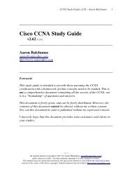
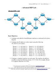
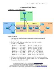
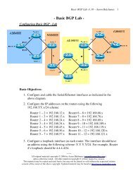
Consider the above diagram. The following demonstrates the steps required<br />
for HostA to communicate with HostB:<br />
• First, HostA will determine if the destination IP address of 10.1.1.6 is<br />
itself. If that address is configured on a local interface, the packet<br />
never leaves HostA. In this example, 10.1.1.6 is not locally<br />
configured on HostA.<br />
• Next, HostA will determine if the 10.1.1.6 address is on the same<br />
network or subnet as itself. HostA consults its local routing table to<br />
make this determination. In this example, the subnet mask is /16.<br />
Thus, HostA’s IP address of 10.1.1.5 <strong>and</strong> the destination address of<br />
10.1.1.6 are on the same network (10.1).<br />
• Because HostA <strong>and</strong> HostB are on the same network, HostA will then<br />
broadcast an ARP request, asking for the MAC address of the<br />
10.1.1.6 address.<br />
• HostB responds to the ARP request with an ARP reply, containing its<br />
MAC address (AAAA.BBBB.CCCC).<br />
• HostA can now construct a Layer-2 frame, with a destination of<br />
HostB’s MAC address. HostA forwards this frame to the switch,<br />
which then forwards the frame to HostB.<br />
* * *<br />
All original material copyright © 2013 by Aaron Balchunas (aaron@routeralley.com),<br />
unless otherwise noted. All other material copyright © of their respective owners.<br />
This material may be copied <strong>and</strong> used freely, but may not be altered or sold without the expressed written<br />
consent of the owner of the above copyright. Updated material may be found at http://www.routeralley.com.
<strong>IPv4</strong> <strong>Addressing</strong> <strong>and</strong> <strong>Subnetting</strong> v1.41 – Aaron Balchunas<br />
21<br />
Resolving Logical Addresses to Hardware Addresses (continued)<br />
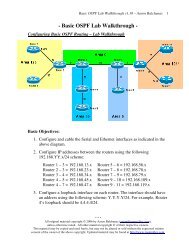
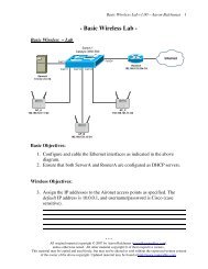
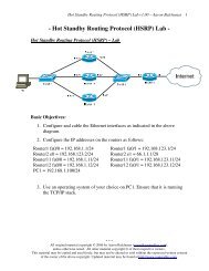
Now consider a slightly modified scenario between HostA <strong>and</strong> HostB:<br />
• Again, HostA will determine if the destination IP address of 10.2.1.5<br />
is itself. In this example, 10.2.1.5 is not locally configured on HostA.<br />
• Next, HostA will determine if the 10.2.1.5 address is on the same<br />
network or subnet as itself. In this example, the subnet mask is /16.<br />
Thus, HostA’s IP address of 10.1.1.5 <strong>and</strong> the destination address of<br />
10.2.1.5 are not on the same network.<br />
• Because HostA <strong>and</strong> HostB are not on the same network, HostA will<br />
parse its local routing table for a route to this destination network of<br />
10.2.x.x/16. Hosts are commonly configured with a default gateway<br />
to reach all other destination networks.<br />
• HostA determines that the 10.1.1.1 address on <strong>Router</strong>A is its default<br />
gateway. HostA will then broadcast an ARP request, asking for the<br />
MAC address of the 10.1.1.1 address.<br />
• <strong>Router</strong>A responds to the ARP request with an ARP reply containing<br />
its MAC address (4444.5555.6666). HostA can now construct a<br />
Layer-2 frame, with a destination of <strong>Router</strong>A’s MAC address.<br />
• Once <strong>Router</strong>A receives the frame, it will parse its own routing table<br />
for a route to the destination network of 10.2.x.x/16. It determines that<br />
this network is directly attached off of its Ethernet2 interface.<br />
<strong>Router</strong>A then broadcasts an ARP request for the 10.2.1.5 address.<br />
• HostB responds to the ARP request with an ARP reply containing its<br />
MAC address (AAAA.BBBB.CCCC). <strong>Router</strong>A can now construct a<br />
Layer-2 frame, with a destination of HostB’s MAC address.<br />
* * *<br />
All original material copyright © 2013 by Aaron Balchunas (aaron@routeralley.com),<br />
unless otherwise noted. All other material copyright © of their respective owners.<br />
This material may be copied <strong>and</strong> used freely, but may not be altered or sold without the expressed written<br />
consent of the owner of the above copyright. Updated material may be found at http://www.routeralley.com.
<strong>IPv4</strong> <strong>Addressing</strong> <strong>and</strong> <strong>Subnetting</strong> v1.41 – Aaron Balchunas<br />
22<br />
Resolving Logical Addresses to Hardware Addresses (continued)<br />
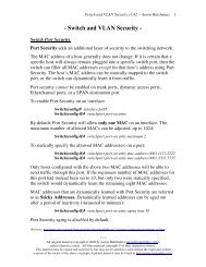
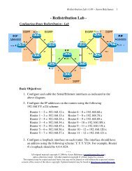
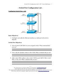
Consider the following example again:<br />
Note that as a packet is routed, the source <strong>and</strong> destination IP address remain<br />
unchanged. However, both the source <strong>and</strong> destination MAC address did<br />
change.<br />
This is because a MAC address contains no network hierarchy, <strong>and</strong> thus is<br />
only significant on the local network. In the above scenario, HostA <strong>and</strong><br />
HostB could not communicate directly using Layer-2 addressing. At every<br />
routed hop, the source <strong>and</strong> destination MAC address are adjusted to reflect<br />
the source <strong>and</strong> destination hosts on the local network.<br />
The source <strong>and</strong> destination IP address will only be changed if NAT is used.<br />
The ARP Table<br />
A host can build an ARP table that contains a list of IP to MAC address<br />
translations. The ARP table is only locally significant to that host. There are<br />
two methods to populate an ARP table:<br />
• Statically<br />
• Dynamically<br />
A static ARP entry is created manually on a host, <strong>and</strong> will remain<br />
permanently until purposely removed. More commonly, ARP tables are built<br />
dynamically by caching ARP replies. Cached entries will eventually be<br />
aged out of the ARP table. The aging time will vary depending on the<br />
operating system, <strong>and</strong> can range from several seconds to several hours.<br />
* * *<br />
All original material copyright © 2013 by Aaron Balchunas (aaron@routeralley.com),<br />
unless otherwise noted. All other material copyright © of their respective owners.<br />
This material may be copied <strong>and</strong> used freely, but may not be altered or sold without the expressed written<br />
consent of the owner of the above copyright. Updated material may be found at http://www.routeralley.com.
<strong>IPv4</strong> <strong>Addressing</strong> <strong>and</strong> <strong>Subnetting</strong> v1.41 – Aaron Balchunas<br />
23<br />
Troubleshooting IP using ICMP<br />
The Internet Control Message Protocol (ICMP) is used for a multitude of<br />
informational <strong>and</strong> error messaging purposes.<br />
The following is a list of common ICMP types <strong>and</strong> codes:<br />
Type Code Description<br />
0 0 Echo Reply<br />
3<br />
- Destination Unreachable<br />
0 Network Unreachable<br />
1 Host Unreachable<br />
2 Protocol Unreachable<br />
3 Port Unreachable<br />
4 Fragmentation Needed – Don’t Fragment Flag Set<br />
6 Destination Network Unknown<br />
7 Destination Host Unknown<br />
9 Destination Network Administratively Prohibited<br />
10 Destination Host Administratively Prohibited<br />
5 Redirect<br />
8 Echo<br />
11 TTL Exceeded<br />
The two most common troubleshooting tools that utilize ICMP are:<br />
• Packet Internet Groper (ping)<br />
• Traceroute<br />
Ping is a core connectivity troubleshooting tool, which utilizes the Echo<br />
Request <strong>and</strong> Echo Reply ICMP messages to determine if an IP address is<br />
reachable <strong>and</strong> responding. Ping will additionally provide the round-trip<br />
time between the source <strong>and</strong> destination, usually measured in milliseconds.<br />
Traceroute determines the routing path a packet takes to reach its<br />
destination. Traceroute will not only identify each router the packet has been<br />
forwarded through, but will also measure the delay experienced at each<br />
router hop.<br />
* * *<br />
All original material copyright © 2013 by Aaron Balchunas (aaron@routeralley.com),<br />
unless otherwise noted. All other material copyright © of their respective owners.<br />
This material may be copied <strong>and</strong> used freely, but may not be altered or sold without the expressed written<br />
consent of the owner of the above copyright. Updated material may be found at http://www.routeralley.com.