Open Shortest Path First (OSPF) - Router Alley
Open Shortest Path First (OSPF) - Router Alley
Open Shortest Path First (OSPF) - Router Alley
Create successful ePaper yourself
Turn your PDF publications into a flip-book with our unique Google optimized e-Paper software.
<strong>OSPF</strong> v1.31 – Aaron Balchunas<br />
1<br />
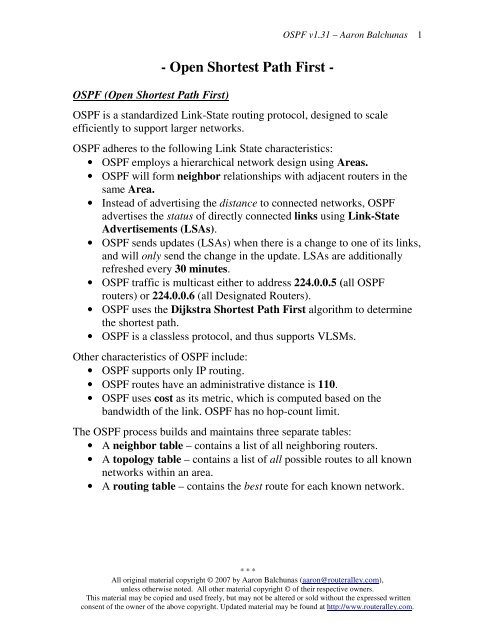
<strong>OSPF</strong> (<strong>Open</strong> <strong>Shortest</strong> <strong>Path</strong> <strong>First</strong>)<br />
- <strong>Open</strong> <strong>Shortest</strong> <strong>Path</strong> <strong>First</strong> -<br />
<strong>OSPF</strong> is a standardized Link-State routing protocol, designed to scale<br />
efficiently to support larger networks.<br />
<strong>OSPF</strong> adheres to the following Link State characteristics:<br />
• <strong>OSPF</strong> employs a hierarchical network design using Areas.<br />
• <strong>OSPF</strong> will form neighbor relationships with adjacent routers in the<br />
same Area.<br />
• Instead of advertising the distance to connected networks, <strong>OSPF</strong><br />
advertises the status of directly connected links using Link-State<br />
Advertisements (LSAs).<br />
• <strong>OSPF</strong> sends updates (LSAs) when there is a change to one of its links,<br />
and will only send the change in the update. LSAs are additionally<br />
refreshed every 30 minutes.<br />
• <strong>OSPF</strong> traffic is multicast either to address 224.0.0.5 (all <strong>OSPF</strong><br />
routers) or 224.0.0.6 (all Designated <strong>Router</strong>s).<br />
• <strong>OSPF</strong> uses the Dijkstra <strong>Shortest</strong> <strong>Path</strong> <strong>First</strong> algorithm to determine<br />
the shortest path.<br />
• <strong>OSPF</strong> is a classless protocol, and thus supports VLSMs.<br />
Other characteristics of <strong>OSPF</strong> include:<br />
• <strong>OSPF</strong> supports only IP routing.<br />
• <strong>OSPF</strong> routes have an administrative distance is 110.<br />
• <strong>OSPF</strong> uses cost as its metric, which is computed based on the<br />
bandwidth of the link. <strong>OSPF</strong> has no hop-count limit.<br />
The <strong>OSPF</strong> process builds and maintains three separate tables:<br />
• A neighbor table – contains a list of all neighboring routers.<br />
• A topology table – contains a list of all possible routes to all known<br />
networks within an area.<br />
• A routing table – contains the best route for each known network.<br />
* * *<br />
All original material copyright © 2007 by Aaron Balchunas (aaron@routeralley.com),<br />
unless otherwise noted. All other material copyright © of their respective owners.<br />
This material may be copied and used freely, but may not be altered or sold without the expressed written<br />
consent of the owner of the above copyright. Updated material may be found at http://www.routeralley.com.
<strong>OSPF</strong> v1.31 – Aaron Balchunas<br />
2<br />
<strong>OSPF</strong> Neighbors<br />
<strong>OSPF</strong> forms neighbor relationships, called adjacencies, with other routers in<br />
the same Area by exchanging Hello packets to multicast address 224.0.0.5.<br />
Only after an adjacency is formed can routers share routing information.<br />
Each <strong>OSPF</strong> router is identified by a unique <strong>Router</strong> ID. The <strong>Router</strong> ID can<br />
be determined in one of three ways:<br />
• The <strong>Router</strong> ID can be manually specified.<br />
• If not manually specified, the highest IP address configured on any<br />
Loopback interface on the router will become the <strong>Router</strong> ID.<br />
• If no loopback interface exists, the highest IP address configured on<br />
any Physical interface will become the <strong>Router</strong> ID.<br />
By default, Hello packets are sent out <strong>OSPF</strong>-enabled interfaces every 10<br />
seconds for broadcast and point-to-point interfaces, and 30 seconds for nonbroadcast<br />
and point-to-multipoint interfaces.<br />
<strong>OSPF</strong> also has a Dead Interval, which indicates how long a router will wait<br />
without hearing any hellos before announcing a neighbor as “down.” Default<br />
for the Dead Interval is 40 seconds for broadcast and point-to-point<br />
interfaces, and 120 seconds for non-broadcast and point-to-multipoint<br />
interfaces. Notice that, by default, the dead interval timer is four times the<br />
Hello interval.<br />
These timers can be adjusted on a per interface basis:<br />
<strong>Router</strong>(config-if)# ip ospf hello-interval 15<br />
<strong>Router</strong>(config-if)# ip ospf dead-interval 60<br />
* * *<br />
All original material copyright © 2007 by Aaron Balchunas (aaron@routeralley.com),<br />
unless otherwise noted. All other material copyright © of their respective owners.<br />
This material may be copied and used freely, but may not be altered or sold without the expressed written<br />
consent of the owner of the above copyright. Updated material may be found at http://www.routeralley.com.
<strong>OSPF</strong> v1.31 – Aaron Balchunas<br />
3<br />
<strong>OSPF</strong> Neighbors (continued)<br />
<strong>OSPF</strong> routers will only become neighbors if the following parameters within<br />
a Hello packet are identical on each router:<br />
• Area ID<br />
• Area Type (stub, NSSA, etc.)<br />
• Prefix<br />
• Subnet Mask<br />
• Hello Interval<br />
• Dead Interval<br />
• Network Type (broadcast, point-to-point, etc.)<br />
• Authentication<br />
The Hello packets also serve as keepalives to allow routers to quickly<br />
discover if a neighbor is down. Hello packets also contain a neighbor field<br />
that lists the <strong>Router</strong> IDs of all neighbors the router is connected to.<br />
A neighbor table is constructed from the <strong>OSPF</strong> Hello packets, which<br />
includes the following information:<br />
• The <strong>Router</strong> ID of each neighboring router<br />
• The current “state” of each neighboring router<br />
• The interface directly connecting to each neighbor<br />
• The IP address of the remote interface of each neighbor<br />
(Reference: http://www.cisco.com/warp/public/104/29.html)<br />
* * *<br />
All original material copyright © 2007 by Aaron Balchunas (aaron@routeralley.com),<br />
unless otherwise noted. All other material copyright © of their respective owners.<br />
This material may be copied and used freely, but may not be altered or sold without the expressed written<br />
consent of the owner of the above copyright. Updated material may be found at http://www.routeralley.com.
<strong>OSPF</strong> v1.31 – Aaron Balchunas<br />
4<br />
<strong>OSPF</strong> Designated <strong>Router</strong>s<br />
In multi-access networks such as<br />
Ethernet, there is the possibility of<br />
many neighbor relationships on the<br />
same physical segment. In the above<br />
example, four routers are connected<br />
into the same multi-access segment.<br />
Using the following formula (where<br />
“n” is the number of routers):<br />
n(n-1)/2<br />
…..it is apparent that 6 separate adjacencies are needed for a fully meshed<br />
network. Increase the number of routers to five, and 10 separate adjacencies<br />
would be required. This leads to a considerable amount of unnecessary Link<br />
State Advertisement (LSA) traffic.<br />
If a link off of <strong>Router</strong> A were to fail, it would flood this information to all<br />
neighbors. Each neighbor, in turn, would then flood that same information to<br />
all other neighbors. This is a waste of bandwidth and processor load.<br />
To prevent this, <strong>OSPF</strong> will elect a Designated <strong>Router</strong> (DR) for each multiaccess<br />
networks, accessed via multicast address 224.0.0.6. For redundancy<br />
purposes, a Backup Designated <strong>Router</strong> (BDR) is also elected.<br />
<strong>OSPF</strong> routers will form adjacencies with the DR and BDR. If a change<br />
occurs to a link, the update is forwarded only to the DR, which then<br />
forwards it to all other routers. This greatly reduces the flooding of LSAs.<br />
DR and BDR elections are determined by a router’s <strong>OSPF</strong> priority, which<br />
is configured on a per-interface basis (a router can have interfaces in<br />
multiple multi-access networks). The router with the highest priority<br />
becomes the DR; second highest becomes the BDR. If there is a tie in<br />
priority, whichever router has the highest <strong>Router</strong> ID will become the DR.<br />
To change the priority on an interface:<br />
<strong>Router</strong>(config-if)# ip ospf priority 125<br />
Default priority on Cisco routers is 1. A priority of 0 will prevent the router<br />
from being elected DR or BDR. Note: The DR election process is not<br />
preemptive. Thus, if a router with a higher priority is added to the network, it<br />
will not automatically supplant an existing DR. Thus, a router that should<br />
never become the DR should always have its priority set to 0.<br />
* * *<br />
All original material copyright © 2007 by Aaron Balchunas (aaron@routeralley.com),<br />
unless otherwise noted. All other material copyright © of their respective owners.<br />
This material may be copied and used freely, but may not be altered or sold without the expressed written<br />
consent of the owner of the above copyright. Updated material may be found at http://www.routeralley.com.
<strong>OSPF</strong> v1.31 – Aaron Balchunas<br />
5<br />
<strong>OSPF</strong> Neighbor States<br />
Neighbor adjacencies will progress through several states, including:<br />
Down – indicates that no Hellos have been heard from the neighboring<br />
router.<br />
Init – indicates a Hello packet has been heard from the neighbor, but twoway<br />
communication has not yet been initialized.<br />
2-Way – indicates that bidirectional communication has been established.<br />
Recall that Hello packets contain a neighbor field. Thus, communication is<br />
considered 2-Way once a router sees its own <strong>Router</strong> ID in its neighbor’s<br />
Hello Packet. Designated and Backup Designated <strong>Router</strong>s are elected at<br />
this stage.<br />
ExStart – indicates that the routers are preparing to share link state<br />
information. Master/slave relationships are formed between routers to<br />
determine who will begin the exchange.<br />
Exchange – indicates that the routers are exchanging Database Descriptors<br />
(DBDs). DBDs contain a description of the router’s Topology Database. A<br />
router will examine a neighbor’s DBD to determine if it has information to<br />
share.<br />
Loading – indicates the routers are finally exchanging Link State<br />
Advertisements, containing information about all links connected to each<br />
router. Essentially, routers are sharing their topology tables with each other.<br />
Full – indicates that the routers are fully synchronized. The topology table of<br />
all routers in the area should now be identical. Depending on the “role” of<br />
the neighbor, the state may appear as:<br />
• Full/DR – indicating that the neighbor is a Designated <strong>Router</strong> (DR)<br />
• Full/BDR – indicating that the neighbor is a Backup Designated<br />
<strong>Router</strong> (BDR)<br />
• Full/DROther – indicating that the neighbor is neither the DR or<br />
BDR<br />
On a multi-access network, <strong>OSPF</strong> routers will only form Full adjacencies<br />
with DRs and BDRs. Non-DRs and non-BDRs will still form adjacencies,<br />
but will remain in a 2-Way State. This is normal <strong>OSPF</strong> behavior.<br />
* * *<br />
All original material copyright © 2007 by Aaron Balchunas (aaron@routeralley.com),<br />
unless otherwise noted. All other material copyright © of their respective owners.<br />
This material may be copied and used freely, but may not be altered or sold without the expressed written<br />
consent of the owner of the above copyright. Updated material may be found at http://www.routeralley.com.
<strong>OSPF</strong> v1.31 – Aaron Balchunas<br />
6<br />
<strong>OSPF</strong> Network Types<br />
<strong>OSPF</strong>’s functionality is different across several different network topology<br />
types. <strong>OSPF</strong>’s interaction with Frame Relay will be explained in another<br />
section<br />
Broadcast Multi-Access – indicates a topology where broadcast occurs.<br />
• Examples include Ethernet, Token Ring, and ATM.<br />
• <strong>OSPF</strong> will elect DRs and BDRs.<br />
• Traffic to DRs and BDRs is multicast to 224.0.0.6. Traffic from<br />
DRs and BDRs to other routers is multicast to 224.0.0.5.<br />
• Neighbors do not need to be manually specified.<br />
Point-to-Point – indicates a topology where two routers are directly<br />
connected.<br />
• An example would be a point-to-point T1.<br />
• <strong>OSPF</strong> will not elect DRs and BDRs.<br />
• All <strong>OSPF</strong> traffic is multicast to 224.0.0.5.<br />
• Neighbors do not need to be manually specified.<br />
Point-to-Multipoint – indicates a topology where one interface can connect<br />
to multiple destinations. Each connection between a source and destination<br />
is treated as a point-to-point link.<br />
• An example would be Point-to-Multipoint Frame Relay.<br />
• <strong>OSPF</strong> will not elect DRs and BDRs.<br />
• All <strong>OSPF</strong> traffic is multicast to 224.0.0.5.<br />
• Neighbors do not need to be manually specified.<br />
Non-broadcast Multi-access Network (NBMA) – indicates a topology<br />
where one interface can connect to multiple destinations; however,<br />
broadcasts cannot be sent across a NBMA network.<br />
• An example would be Frame Relay.<br />
• <strong>OSPF</strong> will elect DRs and BDRs.<br />
• <strong>OSPF</strong> neighbors must be manually defined, thus All <strong>OSPF</strong> traffic<br />
is unicast instead of multicast.<br />
Remember: on non-broadcast networks, neighbors must be manually<br />
specified, as multicast Hello’s are not allowed.<br />
* * *<br />
All original material copyright © 2007 by Aaron Balchunas (aaron@routeralley.com),<br />
unless otherwise noted. All other material copyright © of their respective owners.<br />
This material may be copied and used freely, but may not be altered or sold without the expressed written<br />
consent of the owner of the above copyright. Updated material may be found at http://www.routeralley.com.
<strong>OSPF</strong> v1.31 – Aaron Balchunas<br />
7<br />
Configuring <strong>OSPF</strong> Network Types<br />
The default <strong>OSPF</strong> network type for basic Frame Relay is Non-broadcast<br />
Multi-access Network (NBMA). To configure manually:<br />
<strong>Router</strong>(config)# interface s0<br />
<strong>Router</strong>(config-if)# encapsulation frame-relay<br />
<strong>Router</strong>(config-if)# frame-relay map ip 10.1.1.1 101<br />
<strong>Router</strong>(config-if)# ip ospf network non-broadcast<br />
<strong>Router</strong>(config)# router ospf 1<br />
<strong>Router</strong>(config-router)# neighbor 10.1.1.1<br />
Notice that the neighbor was manually specified, as multicasting is not<br />
allowed on an NBMA. However, the Frame-Relay network can be tricked<br />
into allowing broadcasts, eliminating the need to manually specify<br />
neighbors:<br />
<strong>Router</strong>(config)# interface s0<br />
<strong>Router</strong>(config-if)# encapsulation frame-relay<br />
<strong>Router</strong>(config-if)# frame-relay map ip 10.1.1.1 101 broadcast<br />
<strong>Router</strong>(config-if)# ip ospf network broadcast<br />
Notice that the ospf network type has been changed to broadcast, and the<br />
broadcast parameter was added to the frame-relay map command. The<br />
neighbor no longer needs to be specified, as multicasts will be allowed out<br />
this map.<br />
The default <strong>OSPF</strong> network type for Ethernet and Token Ring is Broadcast<br />
Multi-Access. To configure manually:<br />
<strong>Router</strong>(config)# interface e0<br />
<strong>Router</strong>(config-if)# ip ospf network broadcast<br />
The default <strong>OSPF</strong> network type for T1’s (HDLC or PPP) and Point-to-Point<br />
Frame Relay is Point-to-Point. To configure manually:<br />
<strong>Router</strong>(config)# interface s0<br />
<strong>Router</strong>(config-if)# encapsulation frame-relay<br />
<strong>Router</strong>(config)# interface s0.1 point-to-point<br />
<strong>Router</strong>(config-if)# frame-relay map ip 10.1.1.1 101 broadcast<br />
<strong>Router</strong>(config-if)# ip ospf network point-to-point<br />
* * *<br />
All original material copyright © 2007 by Aaron Balchunas (aaron@routeralley.com),<br />
unless otherwise noted. All other material copyright © of their respective owners.<br />
This material may be copied and used freely, but may not be altered or sold without the expressed written<br />
consent of the owner of the above copyright. Updated material may be found at http://www.routeralley.com.
<strong>OSPF</strong> v1.31 – Aaron Balchunas<br />
8<br />
Configuring <strong>OSPF</strong> Network Types (continued)<br />
The default <strong>OSPF</strong> network type for Point-to-Multipoint Frame Relay is still<br />
Non-broadcast Multi-access Network (NBMA). However, <strong>OSPF</strong> supports<br />
an additional network type called Point-to-Multipoint, which will allow<br />
neighbor discovery to occur automatically. To configure:<br />
<strong>Router</strong>(config)# interface s0<br />
<strong>Router</strong>(config-if)# encapsulation frame-relay<br />
<strong>Router</strong>(config)# interface s0.2 multipoint<br />
<strong>Router</strong>(config-if)# frame-relay map ip 10.1.1.1 101 broadcast<br />
<strong>Router</strong>(config-if)# ip ospf network point-to-multipoint<br />
Additionally, a non-broadcast parameter can be added to the ip ospf network<br />
command when specifying point-to-multipoint.<br />
<strong>Router</strong>(config)# interface s0<br />
<strong>Router</strong>(config-if)# encapsulation frame-relay<br />
<strong>Router</strong>(config)# interface s0.2 multipoint<br />
<strong>Router</strong>(config-if)# frame-relay map ip 10.1.1.1 101<br />
<strong>Router</strong>(config-if)# ip ospf network point-to-multipoint non-broadcast<br />
<strong>Router</strong>(config)# router ospf 1<br />
<strong>Router</strong>(config-router)# neighbor 10.1.1.1<br />
Notice the different in configuration. The frame-relay map command no<br />
longer has the broadcast parameter, as broadcasts and multicasts are not<br />
allowed on a non-broadcast network.<br />
Thus, in the <strong>OSPF</strong> router configuration, neighbors must again be manually<br />
specified. Traffic to those neighbors will be unicast instead of multicast.<br />
<strong>OSPF</strong> network types must be set identically on two “neighboring” routers,<br />
otherwise they will never form an adjacency.<br />
* * *<br />
All original material copyright © 2007 by Aaron Balchunas (aaron@routeralley.com),<br />
unless otherwise noted. All other material copyright © of their respective owners.<br />
This material may be copied and used freely, but may not be altered or sold without the expressed written<br />
consent of the owner of the above copyright. Updated material may be found at http://www.routeralley.com.
<strong>OSPF</strong> v1.31 – Aaron Balchunas<br />
9<br />
The <strong>OSPF</strong> Hierarchy<br />
<strong>OSPF</strong> is a hierarchical system that separates an Autonomous System into<br />
individual areas. <strong>OSPF</strong> traffic can either be intra-area (within one area),<br />
inter-area (between separate areas), or external (from another AS).<br />
<strong>OSPF</strong> routers build a Topology Database of all links within their area, and<br />
all routers within an area will have an identical topology database. Routing<br />
updates between these routers will only contain information about links local<br />
to their area. Limiting the topology database to include only the local area<br />
conserves bandwidth and reduces CPU loads.<br />
Area 0 is required for <strong>OSPF</strong> to function, and is considered the “Backbone”<br />
area. As a rule, all other areas must have a connection into Area 0, though<br />
this rule can be bypassed using virtual links (explained shortly). Area 0 is<br />
often referred to as the transit area to connect all other areas.<br />
<strong>OSPF</strong> routers can belong to multiple areas, and will thus contain separate<br />
Topology databases for each area. These routers are known as Area Border<br />
<strong>Router</strong>s (ABRs).<br />
Consider the above example. Three areas exist: Area 0, Area 1, and Area 2.<br />
Area 0, again, is the backbone area for this Autonomous System. Both Area<br />
1 and Area 2 must directly connect to Area 0.<br />
<strong>Router</strong>s A and B belong fully to Area 1, while <strong>Router</strong>s E and F belong fully<br />
to Area 2. These are known as Internal <strong>Router</strong>s.<br />
<strong>Router</strong> C belongs to both Area 0 and Area 1. Thus, it is an ABR. Because it<br />
has an interface in Area 0, it can also be considered a Backbone <strong>Router</strong>.<br />
The same can be said for <strong>Router</strong> D, as it belongs to both Area 0 and Area 2.<br />
* * *<br />
All original material copyright © 2007 by Aaron Balchunas (aaron@routeralley.com),<br />
unless otherwise noted. All other material copyright © of their respective owners.<br />
This material may be copied and used freely, but may not be altered or sold without the expressed written<br />
consent of the owner of the above copyright. Updated material may be found at http://www.routeralley.com.
<strong>OSPF</strong> v1.31 – Aaron Balchunas<br />
10<br />
The <strong>OSPF</strong> Hierarchy (continued)<br />
Now consider the above example. <strong>Router</strong> G has been added, which belongs<br />
to Area 0. However, <strong>Router</strong> G also has a connection to the Internet, which is<br />
outside this Autonomous System.<br />
This makes <strong>Router</strong> G an Autonomous System Border <strong>Router</strong> (ASBR). A<br />
router can become an ASBR in one of two ways:<br />
• By connecting to a separate Autonomous System, such as the Internet<br />
• By redistributing another routing protocol into the <strong>OSPF</strong> process.<br />
ASBRs provide access to external networks. <strong>OSPF</strong> defines two “types” of<br />
external routes:<br />
• Type 2 (E2) – Includes only the external cost to the destination<br />
network. External cost is the metric being advertised from outside the<br />
<strong>OSPF</strong> domain. This is the default type assigned to external routes.<br />
• Type 1 (E1) – Includes both the external cost, and the internal cost to<br />
reach the ASBR, to determine the total metric to reach the destination<br />
network. Type 1 routes are always preferred over Type 2 routes to the<br />
same destination.<br />
Thus, the four separate <strong>OSPF</strong> router types are as follows:<br />
• Internal <strong>Router</strong>s – all router interfaces belong to only one Area.<br />
• Area Border <strong>Router</strong>s (ABRs) – contains interfaces in at least two<br />
separate areas<br />
• Backbone <strong>Router</strong>s – contain at least one interface in Area 0<br />
• Autonomous System Border <strong>Router</strong>s (ASBRs) – contain a<br />
connection to a separate Autonomous System<br />
* * *<br />
All original material copyright © 2007 by Aaron Balchunas (aaron@routeralley.com),<br />
unless otherwise noted. All other material copyright © of their respective owners.<br />
This material may be copied and used freely, but may not be altered or sold without the expressed written<br />
consent of the owner of the above copyright. Updated material may be found at http://www.routeralley.com.
<strong>OSPF</strong> v1.31 – Aaron Balchunas<br />
11<br />
LSAs and the <strong>OSPF</strong> Topology Database<br />
<strong>OSPF</strong>, as a link-state routing protocol, does not rely on routing-by-rumor as<br />
RIP and IGRP do.<br />
Instead, <strong>OSPF</strong> routers keep track of the status of links within their respective<br />
areas. A link is simply a router interface. From these lists of links and their<br />
respective statuses, the topology database is created. <strong>OSPF</strong> routers forward<br />
link-state advertisements (LSAs) to ensure the topology database is<br />
consistent on each router within an area.<br />
Several LSA types exist:<br />
• <strong>Router</strong> LSA (Type 1) – Contains a list of all links local to the router, and<br />
the status and “cost” of those links. Type 1 LSAs are generated by all<br />
routers in <strong>OSPF</strong>, and are flooded to all other routers within the local area.<br />
• Network LSA (Type 2) – Generated by all Designated <strong>Router</strong>s in <strong>OSPF</strong>,<br />
and contains a list of all routers attached to the Designated <strong>Router</strong>.<br />
• Network Summary LSA (Type 3) – Generated by all ABRs in <strong>OSPF</strong>,<br />
and contains a list of all destination networks within an area. Type 3<br />
LSAs are sent between areas to allow inter-area communication to occur.<br />
• ASBR Summary LSA (Type 4) – Generated by ABRs in <strong>OSPF</strong>, and<br />
contains a route to any ASBRs in the <strong>OSPF</strong> system. Type 4 LSAs are<br />
sent from an ABR into its local area, so that Internal routers know how to<br />
exit the Autonomous System.<br />
• External LSA (Type 5) – Generated by ASBRs in <strong>OSPF</strong>, and contain<br />
routes to destination networks outside the local Autonomous System.<br />
Type 5 LSAs can also take the form of a default route to all networks<br />
outside the local AS. Type 5 LSAs are flooded to all areas in the <strong>OSPF</strong><br />
system.<br />
Multicast <strong>OSPF</strong> (M<strong>OSPF</strong>) utilizes a Type 6 LSA, but that goes beyond the<br />
scope of this guide.<br />
Later in this section, Type 7 NSSA External LSAs will be described in<br />
detail.<br />
* * *<br />
All original material copyright © 2007 by Aaron Balchunas (aaron@routeralley.com),<br />
unless otherwise noted. All other material copyright © of their respective owners.<br />
This material may be copied and used freely, but may not be altered or sold without the expressed written<br />
consent of the owner of the above copyright. Updated material may be found at http://www.routeralley.com.
<strong>OSPF</strong> v1.31 – Aaron Balchunas<br />
12<br />
LSAs and the <strong>OSPF</strong> Topology Database (continued)<br />
From the above example, the following can be determined:<br />
• <strong>Router</strong>s A, B, E, and F are Internal <strong>Router</strong>s.<br />
• <strong>Router</strong>s C and D are ABRs.<br />
• <strong>Router</strong> G is an ASBR.<br />
All routers will generate <strong>Router</strong> (Type 1) LSAs. For example, <strong>Router</strong> A<br />
will generate a Type 1 LSA that contains the status of links FastEthernet 0/0<br />
and FastEthernet 0/1. This LSA will be flooded to all other routers in Area 1.<br />
Designated <strong>Router</strong>s will generate Network (Type 2) LSAs. For example, if<br />
<strong>Router</strong> C was elected the DR for the multi-access network in Area 1, it<br />
would generate a Type 2 LSA containing a list of all routers attached to it.<br />
Area Border <strong>Router</strong>s (ABRs) will generate Network Summary (Type 3)<br />
LSAs. For example, <strong>Router</strong> C is an ABR between Area 0 and Area 1. It will<br />
thus send Type 3 LSAs into both areas. Type 3 LSAs sent into Area 0 will<br />
contain a list of networks within Area 1, including costs to reach those<br />
networks. Type 3 LSAs sent into Area 1 will contain a list of networks<br />
within Area 0, and all other areas connected to Area 0. This allows Area 1 to<br />
reach any other area, and all other areas to reach Area 1.<br />
* * *<br />
All original material copyright © 2007 by Aaron Balchunas (aaron@routeralley.com),<br />
unless otherwise noted. All other material copyright © of their respective owners.<br />
This material may be copied and used freely, but may not be altered or sold without the expressed written<br />
consent of the owner of the above copyright. Updated material may be found at http://www.routeralley.com.
<strong>OSPF</strong> v1.31 – Aaron Balchunas<br />
13<br />
LSAs and the <strong>OSPF</strong> Topology Database (continued)<br />
ABRs will also generate ASBR Summary (Type 4) LSAs. For example,<br />
<strong>Router</strong> C will send Type 4 LSAs into Area 1 containing a route to the<br />
ASBR, thus providing routers in Area 1 with the path out of the<br />
Autonomous System.<br />
ASBRs will generate External (Type 5) LSAs. For example, <strong>Router</strong> G will<br />
generate Type 5 LSAs that contain routes to network outside the AS. These<br />
Type 5 LSAs will be flooded to routers of all areas.<br />
Each type of LSA is propagated under three circumstances:<br />
• When a new adjacency is formed.<br />
• When a change occurs to the topology table.<br />
• When an LSA reaches its maximum age (every 30 minutes, by<br />
default).<br />
Thus, though <strong>OSPF</strong> is typically recognized to only send updates when a<br />
change occurs, LSA’s are still periodically refreshed every 30 minutes.<br />
* * *<br />
All original material copyright © 2007 by Aaron Balchunas (aaron@routeralley.com),<br />
unless otherwise noted. All other material copyright © of their respective owners.<br />
This material may be copied and used freely, but may not be altered or sold without the expressed written<br />
consent of the owner of the above copyright. Updated material may be found at http://www.routeralley.com.
<strong>OSPF</strong> v1.31 – Aaron Balchunas<br />
14<br />
The <strong>OSPF</strong> Metric<br />
<strong>OSPF</strong> determines the best (or shortest) path to a destination network using a<br />
cost metric, which is based on the bandwidth of interfaces. The total cost of<br />
a route is the sum of all outgoing interface costs. Lowest cost is preferred.<br />
Cisco applies default costs to specific interface types:<br />
Type<br />
Cost<br />
Serial (56K) 1785<br />
Serial (64K) 1562<br />
T1 (1.544Mbps) 64<br />
Token Ring (4Mbps) 25<br />
Ethernet (10 Mbps) 10<br />
Token Ring (16 Mbps) 6<br />
Fast Ethernet 1<br />
On Serial interfaces, <strong>OSPF</strong> will use the configured bandwidth (measured in<br />
Kbps) to determine the cost:<br />
<strong>Router</strong>(config)# interface s0<br />
<strong>Router</strong>(config-if)# bandwidth 64<br />
The default cost of an interface can be superseded:<br />
<strong>Router</strong>(config)# interface e0<br />
<strong>Router</strong>(config-if)# ip ospf cost 5<br />
Changing the cost of an interface can alter which path <strong>OSPF</strong> deems the<br />
“shortest,” and thus should be used with great care.<br />
To alter how <strong>OSPF</strong> calculates its default metrics for interfaces:<br />
<strong>Router</strong>(config)# router ospf 1<br />
<strong>Router</strong>(config-router)# ospf auto-cost reference-bandwidth 100<br />
The above ospf auto-cost command has a value of 100 configured, which is<br />
actually the default. This indicates that a 100Mbps link will have a cost of 1<br />
(because 100/100 is 1). All other costs are based off of this. For example, the<br />
cost of 4 Mbps Token Ring is 25 because 100/4 = 25.<br />
* * *<br />
All original material copyright © 2007 by Aaron Balchunas (aaron@routeralley.com),<br />
unless otherwise noted. All other material copyright © of their respective owners.<br />
This material may be copied and used freely, but may not be altered or sold without the expressed written<br />
consent of the owner of the above copyright. Updated material may be found at http://www.routeralley.com.
<strong>OSPF</strong> v1.31 – Aaron Balchunas<br />
15<br />
Configuring Basic <strong>OSPF</strong><br />
Routing protocol configuration occurs in Global Configuration mode. On<br />
<strong>Router</strong> A, to configure <strong>OSPF</strong>:<br />
<strong>Router</strong>A(config)# router ospf 1<br />
<strong>Router</strong>A(config-router)# router-id 1.1.1.1<br />
<strong>Router</strong>A(config-router)# network 172.16.0.0 0.0.255.255 area 1<br />
<strong>Router</strong>A(config-router)# network 172.17.0.0 0.0.255.255 area 0<br />
The first command, router ospf 1, enables the <strong>OSPF</strong> process. The “1”<br />
indicates the <strong>OSPF</strong> process ID, and can be unique on each router. The<br />
process ID allows multiple <strong>OSPF</strong> processes to run on the same router. The<br />
router-id command assigns a unique <strong>OSPF</strong> ID of 1.1.1.1 for this router.<br />
Note the use of a wildcard mask instead of a subnet mask in the network<br />
statement. With <strong>OSPF</strong>, we’re not telling the router what networks to<br />
advertise; we’re telling the router to place certain interfaces into specific<br />
areas, so those routers can form neighbor relationships. The wildcard mask<br />
0.0.255.255 tells us that the last two octets can match any number.<br />
The first network statement places interface E0 on <strong>Router</strong> A into Area 1.<br />
Likewise, the second network statement places interface S0 on <strong>Router</strong> A into<br />
Area 0. The network statement could have been written more specifically:<br />
<strong>Router</strong>A(config)# router ospf 1<br />
<strong>Router</strong>A(config-router)# network 172.16.1.2 0.0.0.0 area 1<br />
<strong>Router</strong>A(config-router)# network 172.17.1.1 0.0.0.0 area 0<br />
In order for <strong>Router</strong> B to form a neighbor relationship with <strong>Router</strong> A, its<br />
connecting interface must be put in the same Area as <strong>Router</strong> A:<br />
<strong>Router</strong>B(config)# router ospf 1<br />
<strong>Router</strong>A(config-router)# router-id 2.2.2.2<br />
<strong>Router</strong>B(config-router)# network 172.17.1.2 0.0.0.0 area 0<br />
<strong>Router</strong>B(config-router)# network 172.18.1.1 0.0.0.0 area 2<br />
If <strong>Router</strong> B’s S0 interface was placed in a different area than <strong>Router</strong> A’s S0<br />
interface, the two routers would never form a neighbor relationship, and<br />
never share routing updates.<br />
* * *<br />
All original material copyright © 2007 by Aaron Balchunas (aaron@routeralley.com),<br />
unless otherwise noted. All other material copyright © of their respective owners.<br />
This material may be copied and used freely, but may not be altered or sold without the expressed written<br />
consent of the owner of the above copyright. Updated material may be found at http://www.routeralley.com.
<strong>OSPF</strong> v1.31 – Aaron Balchunas<br />
16<br />
<strong>OSPF</strong> Passive-Interfaces<br />
It is possible to control which router interfaces will participate in the <strong>OSPF</strong><br />
process. Just as with EIGRP and RIP, we can use the passive-interface<br />
command.<br />
However, please note that the passive-interface command works differently<br />
with <strong>OSPF</strong> than with RIP or IGRP. <strong>OSPF</strong> will no longer form neighbor<br />
relationships out of a “passive” interface, thus this command prevents<br />
updates from being sent or received out of this interface:<br />
<strong>Router</strong>C(config)# router ospf 1<br />
<strong>Router</strong>C(config-router)# network 10.4.0.0 0.0.255.255 area 0<br />
<strong>Router</strong>C(config-router)# network 10.2.0.0 0.0.255.255 area 0<br />
<strong>Router</strong>C(config-router)# passive-interface s0<br />
<strong>Router</strong> C will not form a neighbor adjacency with <strong>Router</strong> B.<br />
It is possible to configure all interfaces to be passive using the passiveinterface<br />
default command, and then individually use the no passiveinterface<br />
command on the interfaces that neighbors should be formed on:<br />
<strong>Router</strong>C(config)# router ospf 1<br />
<strong>Router</strong>C(config-router)# network 10.4.0.0 0.0.255.255 area 0<br />
<strong>Router</strong>C(config-router)# network 10.2.0.0 0.0.255.255 area 0<br />
<strong>Router</strong>C(config-router)# passive-interface default<br />
<strong>Router</strong>C(config-router)# no passive-interface e0<br />
Always remember, that the passive-interface command will prevent <strong>OSPF</strong><br />
(and EIGRP) from forming neighbor relationships out of that interface. No<br />
routing updates are passed in either direction.<br />
* * *<br />
All original material copyright © 2007 by Aaron Balchunas (aaron@routeralley.com),<br />
unless otherwise noted. All other material copyright © of their respective owners.<br />
This material may be copied and used freely, but may not be altered or sold without the expressed written<br />
consent of the owner of the above copyright. Updated material may be found at http://www.routeralley.com.
<strong>OSPF</strong> v1.31 – Aaron Balchunas<br />
17<br />
<strong>OSPF</strong> Authentication<br />
<strong>OSPF</strong> supports authentication to secure routing updates. However, <strong>OSPF</strong><br />
authentication is configured differently than RIP or EIGRP authentication.<br />
Two forms of <strong>OSPF</strong> authentication exist, using either clear-text or an MD5<br />
hash. To configure clear-text authentication, the first step is to enable<br />
authentication for the area, under the <strong>OSPF</strong> routing process:<br />
<strong>Router</strong>A(config)# router ospf 1<br />
<strong>Router</strong>A(config-router)# network 172.17.0.0 0.0.255.255 area 0<br />
<strong>Router</strong>A(config-router)# area 0 authentication<br />
Then, the authentication key must be configured on the interface:<br />
<strong>Router</strong>A(config)# interface s0<br />
<strong>Router</strong>A(config-if)# ip ospf authentication<br />
<strong>Router</strong>A(config-if)# ip ospf authentication-key MYKEY<br />
To configure MD5-hashed authentication, the first step is also to enable<br />
authentication for the area under the <strong>OSPF</strong> process:<br />
<strong>Router</strong>A(config)# router ospf 1<br />
<strong>Router</strong>A(config-router)# network 172.17.0.0 0.0.255.255 area 0<br />
<strong>Router</strong>A(config-router)# area 0 authentication message-digest<br />
Notice the additional parameter message-digest included with the area 0<br />
authentication command. Next, the hashed authentication key must be<br />
configured on the interface:<br />
<strong>Router</strong>A(config)# interface s0<br />
<strong>Router</strong>A(config-router)# ip ospf message-digest-key 10 md5 MYKEY<br />
Area authentication must be enabled on all routers in the area, and the form<br />
of authentication must be identical (clear-text or MD5). The authentication<br />
keys do not need to be the same on every router in the <strong>OSPF</strong> area, but must<br />
be the same on interfaces connecting two neighbors.<br />
Please note: if authentication is enabled for Area 0, the same authentication<br />
must be configured on Virtual Links, as they are “extensions” of Area 0.<br />
* * *<br />
All original material copyright © 2007 by Aaron Balchunas (aaron@routeralley.com),<br />
unless otherwise noted. All other material copyright © of their respective owners.<br />
This material may be copied and used freely, but may not be altered or sold without the expressed written<br />
consent of the owner of the above copyright. Updated material may be found at http://www.routeralley.com.
<strong>OSPF</strong> v1.31 – Aaron Balchunas<br />
18<br />
<strong>OSPF</strong> Virtual Links<br />
Earlier in this guide, it was stated that all areas must directly connect into<br />
Area 0, as a rule. In the above example, Area 2 has no direct connection to<br />
Area 0, but must transit through Area 1 to reach the backbone area. In<br />
normal <strong>OSPF</strong> operation, this shouldn’t be possible.<br />
There may be certain circumstances that may prevent an area from directly<br />
connecting into Area 0. Virtual links can be used as a workaround, to<br />
logically connect separated areas to Area 0. In the above example, a virtual<br />
link would essentially create a tunnel from Area 2 to Area 0, using Area 1 a<br />
transit area. One end of the Virtual Link must be connected to Area 0.<br />
Configuration occurs on the Area Border <strong>Router</strong>s (ABRs) connecting Area<br />
1 to Area 2 (<strong>Router</strong> B), and Area 1 to Area 0 (<strong>Router</strong> C). Configuration on<br />
<strong>Router</strong> B would be as follows:<br />
<strong>Router</strong>B(config)# router ospf 1<br />
<strong>Router</strong>B(config-router)# router-id 2.2.2.2<br />
<strong>Router</strong>B(config-router)# area 1 virtual-link 3.3.3.3<br />
The first command enables the ospf process. The second command manually<br />
sets the router-id for <strong>Router</strong> B to 2.2.2.2.<br />
The third command actually creates the virtual-link. Notice that it specifies<br />
area 1, which is the transit area. Finally, the command points to the remote<br />
ABR’s <strong>Router</strong> ID of 3.3.3.3.<br />
Configuration on <strong>Router</strong> C would be as follows:<br />
<strong>Router</strong>C(config)# router ospf 1<br />
<strong>Router</strong>C(config-router)# router-id 3.3.3.3<br />
<strong>Router</strong>C(config-router)# area 1 virtual-link 2.2.2.2<br />
* * *<br />
All original material copyright © 2007 by Aaron Balchunas (aaron@routeralley.com),<br />
unless otherwise noted. All other material copyright © of their respective owners.<br />
This material may be copied and used freely, but may not be altered or sold without the expressed written<br />
consent of the owner of the above copyright. Updated material may be found at http://www.routeralley.com.
<strong>OSPF</strong> v1.31 – Aaron Balchunas<br />
19<br />
<strong>OSPF</strong> Virtual Links (continued)<br />
It is also possible to have two separated (or discontiguous) Area 0’s. In order<br />
for <strong>OSPF</strong> to function properly, the two Area 0’s must be connected using a<br />
virtual link.<br />
Again, configuration occurs on the transit area’s ABRs:<br />
<strong>Router</strong>B(config)# router ospf 1<br />
<strong>Router</strong>B(config-router)# router-id 2.2.2.2<br />
<strong>Router</strong>B(config-router)# area 1 virtual-link 3.3.3.3<br />
<strong>Router</strong>C(config)# router ospf 1<br />
<strong>Router</strong>C(config-router)# router-id 3.3.3.3<br />
<strong>Router</strong>C(config-router)# area 1 virtual-link 2.2.2.2<br />
Always remember: the area specified in the virtual-link command is the<br />
transit area. Additionally, the transit area cannot be a stub area.<br />
As stated earlier, if authentication is enabled for Area 0, the same<br />
authentication must be configured on Virtual Links, as they are “extensions”<br />
of Area 0:<br />
<strong>Router</strong>B(config)# router ospf 1<br />
<strong>Router</strong>B(config-router)# area 1 virtual-link 3.3.3.3 message-digest-key 1 md5 MYKEY<br />
<strong>Router</strong>C(config)# router ospf 1<br />
<strong>Router</strong>C(config-router)# area 1 virtual-link 2.2.2.2 message-digest-key 1 md5 MYKEY<br />
* * *<br />
All original material copyright © 2007 by Aaron Balchunas (aaron@routeralley.com),<br />
unless otherwise noted. All other material copyright © of their respective owners.<br />
This material may be copied and used freely, but may not be altered or sold without the expressed written<br />
consent of the owner of the above copyright. Updated material may be found at http://www.routeralley.com.
<strong>OSPF</strong> v1.31 – Aaron Balchunas<br />
20<br />
Inter-Area <strong>OSPF</strong> Summarization<br />
Consider the above example. <strong>OSPF</strong> is a classless routing protocol, thus all of<br />
the listed networks would be advertised individually. This increases the size<br />
of the topology databases and routing tables on routers in the domain, and<br />
may be undesirable. Advertising only a summary route for inter-area<br />
communication can reduce the load on router CPUs.<br />
For example, all of the networks in Area 1 can be summarized as<br />
10.1.0.0/21. Similarly, all of the networks in Area 2 can be summarized as<br />
10.1.8.0/21.<br />
Inter-area summarization is configured on Area Border <strong>Router</strong>s (ABRs).<br />
Configuration on <strong>Router</strong> A would be as follows:<br />
<strong>Router</strong>A(config)# router ospf 1<br />
<strong>Router</strong>A(config-router)# network 10.1.0.0 0.0.7.255 area 1<br />
<strong>Router</strong>A(config-router)# area 1 range 10.1.0.0 255.255.248.0<br />
The network statement includes all of the 10.1.x.0 networks into Area 1. The<br />
area 1 range command creates a summary route for those networks, which<br />
is then advertised into Area 0, as opposed to each route individually.<br />
Proper design dictates that a static route be created for the summarized<br />
network, pointing to the Null interface. This sends any traffic destined<br />
specifically to the summarized address to the bit-bucket in the sky, in order<br />
to prevent routing loops:<br />
<strong>Router</strong>A(config)# ip route 10.1.0.0 255.255.248.0 null0<br />
In IOS versions 12.1(6) and later, this static route is created automatically.<br />
* * *<br />
All original material copyright © 2007 by Aaron Balchunas (aaron@routeralley.com),<br />
unless otherwise noted. All other material copyright © of their respective owners.<br />
This material may be copied and used freely, but may not be altered or sold without the expressed written<br />
consent of the owner of the above copyright. Updated material may be found at http://www.routeralley.com.
<strong>OSPF</strong> v1.31 – Aaron Balchunas<br />
21<br />
External <strong>OSPF</strong> Summarization<br />
Consider the above example. <strong>Router</strong> B is an Autonomous System Border<br />
<strong>Router</strong> (ASBR). It is possible to redistribute the four “external” networks<br />
into the <strong>OSPF</strong> system. However, a separate route for each network will be<br />
advertised.<br />
Again, this is wasteful. The four external networks can be summarized as<br />
15.0.0.0/14.<br />
External Summarization is configured on ASBRs, and will only<br />
summarize external routes learned by route redistribution. Configuration on<br />
<strong>Router</strong> B would be as follows:<br />
<strong>Router</strong>B(config)# router ospf 1<br />
<strong>Router</strong>B(config-router)# summary-address 15.0.0.0 255.252.0.0<br />
This summarized route is now propagated to all routers in every <strong>OSPF</strong> area.<br />
Summarization can be used to filter certain routes (true route filtering is<br />
covered in a separate guide). To force <strong>OSPF</strong> to advertise the 15.0.0.0 and<br />
15.1.0.0 networks as a summarized route, but not advertise the 15.2.0.0 and<br />
15.3.0.0 prefixes:<br />
<strong>Router</strong>B(config)# router ospf 1<br />
<strong>Router</strong>B(config-router)# summary-address 15.0.0.0 255.254.0.0<br />
<strong>Router</strong>B(config-router)# summary-address 15.2.0.0 255.255.0.0 not-advertise<br />
<strong>Router</strong>B(config-router)# summary-address 15.3.0.0 255.255.0.0 not-advertise<br />
The first summary-address command summarizes the 15.0.0.0/16 and<br />
15.1.0.0/16 networks to 15.0.0.0/15, and advertises the summary as normal<br />
in the <strong>OSPF</strong> domain. The next two summary-address commands specifically<br />
reference the 15.2.0.0/16 and 15.3.0.0/16 networks, with the not-advertise<br />
parameter. As implied, these networks will not be advertised in <strong>OSPF</strong>.<br />
* * *<br />
All original material copyright © 2007 by Aaron Balchunas (aaron@routeralley.com),<br />
unless otherwise noted. All other material copyright © of their respective owners.<br />
This material may be copied and used freely, but may not be altered or sold without the expressed written<br />
consent of the owner of the above copyright. Updated material may be found at http://www.routeralley.com.
<strong>OSPF</strong> v1.31 – Aaron Balchunas<br />
22<br />
<strong>OSPF</strong> Area Types<br />
In order to control the propagation of LSAs in the <strong>OSPF</strong> domain, several<br />
area types were developed.<br />
Standard Area – A “normal” <strong>OSPF</strong> area.<br />
• <strong>Router</strong>s within a standard area will share <strong>Router</strong> (Type 1) and<br />
Network (Type 2) LSAs to build their topology tables. Once fully<br />
synchronized, routers within an area will all have identical<br />
topology tables.<br />
• Standard areas will accept Network Summary (Type 3) LSAs,<br />
which contain the routes to reach networks in all other areas.<br />
• Standard areas will accept ASBR Summary (Type 4) and External<br />
(Type 5) LSAs, which contain the route to the ASBR and routes to<br />
external networks, respectively.<br />
Configuration of standard areas is straight forward:<br />
<strong>Router</strong>(config)# router ospf 1<br />
<strong>Router</strong>(config-router)# network 10.1.0.0 0.0.7.255 area 1<br />
Stub Area – Prevents external routes from flooding into an area.<br />
• Like Standard areas, Stub area routers will share Type 1 and Type<br />
2 LSAs to build their topology tables.<br />
• Stub areas will also accept Type 3 LSAs to reach other areas.<br />
• Stub areas will not accept Type 4 or Type 5 LSAs, detailing routes<br />
to external networks.<br />
The purpose of Stub areas is to limit the number of LSAs flooded into the<br />
area, to conserve bandwidth and router CPUs. The Stub’s ABR will<br />
automatically inject a default route into the Stub area, so that those routers<br />
can reach the external networks. The ABR will be the next-hop for the<br />
default route.<br />
Configuration of stub areas is relatively simple:<br />
<strong>Router</strong>(config)# router ospf 1<br />
<strong>Router</strong>(config-router)# network 10.1.0.0 0.0.7.255 area 1<br />
<strong>Router</strong>(config-router)# area 1 stub<br />
The area 1 stub command must be configured on all routers in the Stub area.<br />
No ASBRs are allowed in a Stub area.<br />
* * *<br />
All original material copyright © 2007 by Aaron Balchunas (aaron@routeralley.com),<br />
unless otherwise noted. All other material copyright © of their respective owners.<br />
This material may be copied and used freely, but may not be altered or sold without the expressed written<br />
consent of the owner of the above copyright. Updated material may be found at http://www.routeralley.com.
<strong>OSPF</strong> v1.31 – Aaron Balchunas<br />
23<br />
<strong>OSPF</strong> Area Types (continued)<br />
Totally Stubby Area – Prevents both inter-area and external routes from<br />
flooding into an area.<br />
• Like Standard and Stub areas, Totally Stubby area routers will<br />
share Type 1 and Type 2 LSAs to build their topology tables.<br />
• Totally Stubby areas will not accept Type 3 LSAs to other areas.<br />
• Totally Stubby areas will also not accept Type 4 or Type 5 LSAs,<br />
detailing routes to external networks.<br />
Again, the purpose of Totally Stubby areas is to limit the number of LSAs<br />
flooded into the area, to conserve bandwidth and router CPUs. The Stub’s<br />
ABR will instead automatically inject a default route into the Totally<br />
Stubby area, so that those routers can reach both inter-area networks and<br />
external networks. The ABR will be the next-hop for the default route.<br />
Configuration of totally stubby areas is relatively simple:<br />
<strong>Router</strong>(config)# router ospf 1<br />
<strong>Router</strong>(config-router)# network 10.1.0.0 0.0.7.255 area 1<br />
<strong>Router</strong>(config-router)# area 1 stub no-summary<br />
The area 1 stub no-summary command is configured only on the ABR of<br />
the Totally Stubby area; other routers within the area are configured with the<br />
area 1 stub command. No ASBRs are allowed in a Totally Stubby area.<br />
In the above example, if we were to configure Area 1 as a Totally Stubby<br />
area, it would not accept any external routes originating from the ASBR<br />
(<strong>Router</strong> G). It also would not accept any Type 3 LSAs containing route<br />
information about Area 0 and Area 2. Instead, <strong>Router</strong> C (the ABR) will<br />
inject a default route into Area 1, and all routers within Area 1 will use<br />
<strong>Router</strong> C as their gateway to all other networks.<br />
* * *<br />
All original material copyright © 2007 by Aaron Balchunas (aaron@routeralley.com),<br />
unless otherwise noted. All other material copyright © of their respective owners.<br />
This material may be copied and used freely, but may not be altered or sold without the expressed written<br />
consent of the owner of the above copyright. Updated material may be found at http://www.routeralley.com.
<strong>OSPF</strong> v1.31 – Aaron Balchunas<br />
24<br />
<strong>OSPF</strong> Area Types (continued)<br />
More External<br />
Networks<br />
External<br />
Networks<br />
Area 1<br />
<strong>Router</strong> G<br />
Area 2<br />
<strong>Router</strong> A<br />
<strong>Router</strong> E<br />
<strong>Router</strong> C<br />
<strong>Router</strong> D<br />
<strong>Router</strong> B<br />
Area 0<br />
<strong>Router</strong> F<br />
Not So Stubby Area (NSSA) – Similar to a Stub area; prevents external<br />
routes from flooding into an area, unless those external routes originated<br />
from an ASBR within the NSSA area.<br />
• Like Standard and Stub areas, NSSA area routers will share Type 1<br />
and Type 2 LSAs to build their topology tables.<br />
• NSSA areas will also accept Network Summary (Type 3) LSAs,<br />
which contain the routes to reach networks in all other areas.<br />
• NSSA areas will not accept Type 4 or Type 5 LSAs, detailing<br />
routes to external networks.<br />
• If an ASBR exists within the NSSA area, that ASBR will generate<br />
Type 7 LSAs.<br />
Again, NSSA areas are almost identical to Stub areas. If Area 1 was<br />
configured as an NSSA, it would not accept any external routes originating<br />
from <strong>Router</strong> G (an ASBR outside Area 1).<br />
However, Area 1 also has an ASBR within the area (<strong>Router</strong> A). Those<br />
external routes will be flooded into Area 1 as Type 7 LSAs. These external<br />
routes will not be forwarded to other areas as Type 7 LSAs; instead, they<br />
will be converted into Type 5 LSAs by Area 1’s ABR (<strong>Router</strong> C).<br />
Configuration of NSSA areas is relatively simple:<br />
<strong>Router</strong>(config)# router ospf 1<br />
<strong>Router</strong>(config-router)# network 10.1.0.0 0.0.7.255 area 1<br />
<strong>Router</strong>(config-router)# area 1 nssa<br />
The area 1 nssa command must be applied to all routers in the NSSA area.<br />
* * *<br />
All original material copyright © 2007 by Aaron Balchunas (aaron@routeralley.com),<br />
unless otherwise noted. All other material copyright © of their respective owners.<br />
This material may be copied and used freely, but may not be altered or sold without the expressed written<br />
consent of the owner of the above copyright. Updated material may be found at http://www.routeralley.com.
<strong>OSPF</strong> v1.31 – Aaron Balchunas<br />
25<br />
<strong>OSPF</strong> Area Types (continued)<br />
More External<br />
Networks<br />
External<br />
Networks<br />
Area 1<br />
<strong>Router</strong> G<br />
Area 2<br />
<strong>Router</strong> A<br />
<strong>Router</strong> E<br />
<strong>Router</strong> C<br />
<strong>Router</strong> D<br />
<strong>Router</strong> B<br />
Area 0<br />
<strong>Router</strong> F<br />
Totally Not So Stubby Area (TNSSA) – Similar to a Totally Stubby area;<br />
prevents both inter-area and external routes from flooding into an area,<br />
unless those external routes originated from an ASBR within the NSSA area.<br />
• Like Standard and Stub areas, TNSSA area routers will share Type<br />
1 and Type 2 LSAs to build their topology tables.<br />
• TNSSA areas will not accept Type 3 LSAs to other areas.<br />
• TNSSA areas will not accept Type 4 or Type 5 LSAs, detailing<br />
routes to external networks.<br />
• If an ASBR exists within the TNSSA area, that ASBR will<br />
generate Type 7 LSAs.<br />
With the exception of not accepting inter-area routes, TNSSA areas are<br />
identical in function to NSSA areas.<br />
Configuration of TNSSA areas is relatively simple:<br />
<strong>Router</strong>(config)# router ospf 1<br />
<strong>Router</strong>(config-router)# network 10.1.0.0 0.0.7.255 area 1<br />
<strong>Router</strong>(config-router)# area 1 nssa no-summary<br />
The area 1 nssa no-summary command is configured only on the ABR of<br />
the TNSSA area; other routers within the area are configured with the area 1<br />
nssa command.<br />
* * *<br />
All original material copyright © 2007 by Aaron Balchunas (aaron@routeralley.com),<br />
unless otherwise noted. All other material copyright © of their respective owners.<br />
This material may be copied and used freely, but may not be altered or sold without the expressed written<br />
consent of the owner of the above copyright. Updated material may be found at http://www.routeralley.com.
<strong>OSPF</strong> v1.31 – Aaron Balchunas<br />
26<br />
<strong>OSPF</strong> and Default Routes<br />
We have learned about four types of <strong>OSPF</strong> areas:<br />
• Standard areas<br />
• Totally Stubby areas<br />
• Stub areas<br />
• Not So Stubby areas (NSSA)<br />
The ABRs and ASBRs of Standard areas do not automatically generate (or<br />
inject) default routes into the area. Consider the following example:<br />
Area 1<br />
Area 0<br />
External<br />
Networks<br />
<strong>Router</strong> A<br />
<strong>Router</strong> C<br />
<strong>Router</strong> B<br />
Assume that Area 1 is configured as a Standard area. <strong>Router</strong> C will forward<br />
Type 3 LSAs from all other areas into Area 1, allowing <strong>Router</strong> A and <strong>Router</strong><br />
B to reach inter-area networks.<br />
Notice also that <strong>Router</strong> A is an ASBR, connecting to an external<br />
Autonomous System. Thus, <strong>Router</strong> A will generate Type 5 LSAs, detailing<br />
the routes to these external networks.<br />
To additionally force <strong>Router</strong> A to generate a default route (indicating itself<br />
as the next hop) for the external networks, and inject this into Area 1. This<br />
default route will be advertised as a Type 5 LSA to all other areas:<br />
<strong>Router</strong>A(config)# router ospf 1<br />
<strong>Router</strong>A(config-router)# default-information originate<br />
<strong>Router</strong> A must have a default route in its routing table in order for the above<br />
command to function. <strong>Router</strong> A’s default route would point to some<br />
upstream router in the external Autonomous System.<br />
If a default route does not exist in its routing table, <strong>Router</strong> A can still be<br />
forced to advertise a default route using the always parameter:<br />
<strong>Router</strong>A(config)# router ospf 1<br />
<strong>Router</strong>A(config-router)# default-information originate always<br />
* * *<br />
All original material copyright © 2007 by Aaron Balchunas (aaron@routeralley.com),<br />
unless otherwise noted. All other material copyright © of their respective owners.<br />
This material may be copied and used freely, but may not be altered or sold without the expressed written<br />
consent of the owner of the above copyright. Updated material may be found at http://www.routeralley.com.
<strong>OSPF</strong> v1.31 – Aaron Balchunas<br />
27<br />
<strong>OSPF</strong> and Default Routes (continued)<br />
The ABRs of Stub and Totally Stubby areas automatically generate (and<br />
inject) a default route (0.0.0.0/0) into the area. <strong>Router</strong>s in Stub areas use<br />
this default route to reach external networks, while routers in Totally Stubby<br />
areas use the default route to reach both inter-area and external networks.<br />
To control the “cost” metric of the default route in Stub or Totally Stubby<br />
areas (configured on the ABR):<br />
<strong>Router</strong>(config)# router ospf 1<br />
<strong>Router</strong>(config-router)# area 1 stub<br />
<strong>Router</strong>(config-router)# area 1 default-cost 10<br />
The ABRs of NSSA areas must be manually configured to generate (and<br />
inject) a default route into the area:<br />
<strong>Router</strong>(config)# router ospf 1<br />
<strong>Router</strong>(config-router)# area 1 nssa default-information-originate<br />
Additionally, the ASBR of an NSSA area can generate and inject a default<br />
route. This default route will be advertised as a Type 7 LSA, as Type 5<br />
LSA’s are not allowed in NSSAs. The command is no different than<br />
injecting a default route from an NSSA ABR:<br />
<strong>Router</strong>(config)# router ospf 1<br />
<strong>Router</strong>(config-router)# area 1 nssa default-information-originate<br />
Reference: (http://www.cisco.com/en/US/tech/tk365/technologies_tech_note09186a0080094a74.shtml)<br />
* * *<br />
All original material copyright © 2007 by Aaron Balchunas (aaron@routeralley.com),<br />
unless otherwise noted. All other material copyright © of their respective owners.<br />
This material may be copied and used freely, but may not be altered or sold without the expressed written<br />
consent of the owner of the above copyright. Updated material may be found at http://www.routeralley.com.
<strong>OSPF</strong> v1.31 – Aaron Balchunas<br />
28<br />
<strong>OSPF</strong> SPF Timers<br />
To adjust the SPF timers in <strong>OSPF</strong>:<br />
<strong>Router</strong>(config)# router ospf 1<br />
<strong>Router</strong>(config-router)# timers spf 10 15<br />
The timers spf command includes two parameters, measured in seconds. The<br />
first (10) indicates the SPF-Delay, or how long the <strong>OSPF</strong> should wait after<br />
receiving a topology change to recalculate the shortest path. The second (15)<br />
indicates the SPF-Holdtime, or how long <strong>OSPF</strong> should wait in between<br />
separate SPF calculations.<br />
The timers spf command has actually become deprecated. It has been<br />
replaced with:<br />
<strong>Router</strong>(config)# router ospf 1<br />
<strong>Router</strong>(config-router)# timers throttle spf 5 10000 80000<br />
The timers throttle spf command includes three parameters, measure in<br />
milliseconds. The first (5) indicates how long <strong>OSPF</strong> should wait after<br />
receiving a topology change to recalculate the shortest path. The second<br />
(10000) indicates the hold-down time, or how long <strong>OSPF</strong> should wait in<br />
between separate SPF calculations. If <strong>OSPF</strong> receives another topology<br />
change during the hold-time interval, it will continue to double the hold-time<br />
interval until it reaches the maximum hold-time (80000).<br />
The purpose of the both SPF timer commands is to prevent <strong>OSPF</strong> from<br />
constantly converging, if the network links are “flapping.” The timers spf<br />
and timers throttle spf commands cannot be used together.<br />
* * *<br />
All original material copyright © 2007 by Aaron Balchunas (aaron@routeralley.com),<br />
unless otherwise noted. All other material copyright © of their respective owners.<br />
This material may be copied and used freely, but may not be altered or sold without the expressed written<br />
consent of the owner of the above copyright. Updated material may be found at http://www.routeralley.com.
<strong>OSPF</strong> v1.31 – Aaron Balchunas<br />
29<br />
Advanced <strong>OSPF</strong> Configuration<br />
To force the <strong>OSPF</strong> process to ignore <strong>OSPF</strong> Multicast (Type 6) LSAs:<br />
<strong>Router</strong>(config)# router ospf 1<br />
<strong>Router</strong>(config-router)# ignore lsa mospf<br />
To force an interface to filter all outgoing <strong>OSPF</strong> LSA’s:<br />
<strong>Router</strong>(config)# interface e0<br />
<strong>Router</strong>(config-if)# ip ospf database-filter all out<br />
Loopback interfaces are treated differently than other interfaces, when<br />
advertised in <strong>OSPF</strong>. <strong>OSPF</strong> will advertise a loopback interface as a specific<br />
“host” route (with a mask of /32 or 255.255.255.255). To force <strong>OSPF</strong> to<br />
advertise a loopback interface with its proper subnet mask:<br />
<strong>Router</strong>(config)# interface loopback0<br />
<strong>Router</strong>(config-if)# ip address 10.50.5.1 255.255.255.0<br />
<strong>Router</strong>(config-if)# ip ospf network point-to-point<br />
* * *<br />
All original material copyright © 2007 by Aaron Balchunas (aaron@routeralley.com),<br />
unless otherwise noted. All other material copyright © of their respective owners.<br />
This material may be copied and used freely, but may not be altered or sold without the expressed written<br />
consent of the owner of the above copyright. Updated material may be found at http://www.routeralley.com.
<strong>OSPF</strong> v1.31 – Aaron Balchunas<br />
30<br />
Troubleshooting <strong>OSPF</strong><br />
To view the <strong>OSPF</strong> Neighbor Table:<br />
<strong>Router</strong># show ip ospf neighbor<br />
Neighbor ID Pri State Dead Time Address Interface<br />
7.7.7.7 1 FULL/ - 00:00:36 150.50.17.2 Serial0<br />
6.6.6.6 1 FULL/DR 00:00:11 150.50.18.1 Ethernet0<br />
The Neighbor Table provides the following information about each<br />
neighbor:<br />
• The <strong>Router</strong> ID of the remote neighbor.<br />
• The <strong>OSPF</strong> priority of the remote neighbor (used for DR/BDR<br />
elections).<br />
• The current neighbor state.<br />
• The dead interval timer.<br />
• The connecting IP address of the remote neighbor.<br />
• The local interface connecting to the remote neighbor.<br />
To view the <strong>OSPF</strong> topology table:<br />
<strong>Router</strong># show ip ospf database<br />
<strong>OSPF</strong> <strong>Router</strong> with ID (9.9.9.9) (Process ID 10)<br />
<strong>Router</strong> Link States (Area 0)<br />
Link ID ADV <strong>Router</strong> Age Seq# Checksum Link count<br />
7.7.7.7 7.7.7.7 329 0x80000007 0x42A0 2<br />
8.8.8.8 8.8.8.8 291 0x80000007 0x9FFC 1<br />
Summary Net Link States (Area 0)<br />
Link ID ADV <strong>Router</strong> Age Seq# Checksum<br />
192.168.12.0 7.7.7.7 103 0x80000005 0x13E4<br />
192.168.34.0 7.7.7.7 105 0x80000003 0x345A<br />
The Topology Table provides the following information:<br />
• The actual link (or route).<br />
• The advertising <strong>Router</strong> ID.<br />
• The link-state age timer.<br />
• The sequence number and checksum for each entry.<br />
(Reference: http://www.cisco.com/en/US/products/sw/iosswrel/ps5187/products_command_reference_chapter09186a008017d02e.html)<br />
* * *<br />
All original material copyright © 2007 by Aaron Balchunas (aaron@routeralley.com),<br />
unless otherwise noted. All other material copyright © of their respective owners.<br />
This material may be copied and used freely, but may not be altered or sold without the expressed written<br />
consent of the owner of the above copyright. Updated material may be found at http://www.routeralley.com.
<strong>OSPF</strong> v1.31 – Aaron Balchunas<br />
31<br />
Troubleshooting <strong>OSPF</strong> (continued)<br />
To view the specific information about an <strong>OSPF</strong> process:<br />
<strong>Router</strong># show ip ospf 1<br />
Routing Process "ospf 1" with ID 9.9.9.9<br />
Supports only single TOS(TOS0) routes<br />
Supports opaque LSA<br />
SPF schedule delay 5 secs, Hold time between two SPFs 10 secs<br />
Minimum LSA interval 5 secs. Minimum LSA arrival 1 secs<br />
Number of external LSA 0. Checksum Sum 0x0<br />
Number of opaque AS LSA 0. Checksum Sum 0x0<br />
Number of DCbitless external and opaque AS LSA 0<br />
Number of DoNotAge external and opaque AS LSA 0<br />
Number of areas in this router is 1. 1 normal 0 stub 0 nssa<br />
External flood list length 0<br />
Area BACKBONE(0)<br />
Number of interfaces in this area is 1<br />
Area has no authentication<br />
SPF algorithm executed 3 times<br />
Area ranges are<br />
Number of LSA 2. Checksum Sum 0xDDEC<br />
Number of opaque link LSA 0. Checksum Sum 0x0<br />
Number of DCbitless LSA 0<br />
Number of indication LSA 0<br />
Number of DoNotAge LSA 0<br />
Flood list length 0<br />
The show ip ospf command provides the following information:<br />
• The local <strong>Router</strong> ID.<br />
• SPF Scheduling information, and various SPF timers.<br />
• The number of interfaces in specific areas, including the type of area.<br />
• The link-state age timer.<br />
• The sequence number and checksum for each entry.<br />
* * *<br />
All original material copyright © 2007 by Aaron Balchunas (aaron@routeralley.com),<br />
unless otherwise noted. All other material copyright © of their respective owners.<br />
This material may be copied and used freely, but may not be altered or sold without the expressed written<br />
consent of the owner of the above copyright. Updated material may be found at http://www.routeralley.com.
<strong>OSPF</strong> v1.31 – Aaron Balchunas<br />
32<br />
Troubleshooting <strong>OSPF</strong> (continued)<br />
To view <strong>OSPF</strong>-specific information on an interface:<br />
<strong>Router</strong># show ip ospf interface s0<br />
Serial0 is up, line protocol is up<br />
Internet Address 192.168.79.2/24, Area 0<br />
Process ID 10, <strong>Router</strong> ID 9.9.9.9, Network Type POINT_TO_POINT, Cost: 64<br />
Transmit Delay is 1 sec, State POINT_TO_POINT,<br />
Timer intervals configured, Hello 10, Dead 40, Wait 40, Retransmit 5<br />
Hello due in 00:00:04<br />
Index 1/1, flood queue length 0<br />
Next 0x0(0)/0x0(0)<br />
Last flood scan length is 1, maximum is 1<br />
Last flood scan time is 0 msec, maximum is 0 msec<br />
Neighbor Count is 1, Adjacent neighbor count is 1<br />
Adjacent with neighbor 7.7.7.7<br />
Suppress hello for 0 neighbor(s)<br />
The show ip ospf interface command provides the following information:<br />
• The local <strong>Router</strong> ID.<br />
• The interface network type.<br />
• The <strong>OSPF</strong> cost for the interface.<br />
• The interface Hello and Dead timers.<br />
• A list of neighbor adjacencies.<br />
To view routing protocol specific information for <strong>OSPF</strong>:<br />
<strong>Router</strong># show ip protocols<br />
Routing Protocol is “ospf 10"<br />
Invalid after 0 seconds, hold down 0, flushed after 0<br />
Outgoing update filter list for all interfaces is<br />
Incoming update filter list for all interfaces is<br />
Routing for Networks:<br />
192.168.79.0 0.0.0.255 area 0<br />
192.168.109.0 0.0.0.255 area 0<br />
Routing Information Sources:<br />
Gateway Distance Last Update<br />
7.7.7.7 110 00:01:05<br />
Distance: (default is 110)<br />
The show ip protocols command provides the following information:<br />
• Locally originated networks that are being advertised.<br />
• Neighboring sources for routing information<br />
• The administrative distance of neighboring sources.<br />
* * *<br />
All original material copyright © 2007 by Aaron Balchunas (aaron@routeralley.com),<br />
unless otherwise noted. All other material copyright © of their respective owners.<br />
This material may be copied and used freely, but may not be altered or sold without the expressed written<br />
consent of the owner of the above copyright. Updated material may be found at http://www.routeralley.com.
<strong>OSPF</strong> v1.31 – Aaron Balchunas<br />
33<br />
Troubleshooting <strong>OSPF</strong> (continued)<br />
To reset an <strong>OSPF</strong> process, including neighbor adjacencies:<br />
<strong>Router</strong># clear ip ospf process<br />
To display information about <strong>OSPF</strong> virtual-links:<br />
<strong>Router</strong># show ip ospf virtual-links<br />
To display routes to both ABRs and ASBRs:<br />
<strong>Router</strong># show ip ospf border-routers<br />
To debug <strong>OSPF</strong> in realtime:<br />
<strong>Router</strong># debug ip ospf adj<br />
<strong>Router</strong># debug ip ospf events<br />
<strong>Router</strong># debug ip ospf hello<br />
* * *<br />
All original material copyright © 2007 by Aaron Balchunas (aaron@routeralley.com),<br />
unless otherwise noted. All other material copyright © of their respective owners.<br />
This material may be copied and used freely, but may not be altered or sold without the expressed written<br />
consent of the owner of the above copyright. Updated material may be found at http://www.routeralley.com.


