Appendix D Location and dimensions of components - RTA
Appendix D Location and dimensions of components - RTA
Appendix D Location and dimensions of components - RTA

Create successful ePaper yourself
Turn your PDF publications into a flip-book with our unique Google optimized e-Paper software.
Traffic Signal Design – <strong>Appendix</strong> D <strong>Location</strong> & Dimensions <strong>of</strong> Components<br />
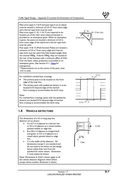
Mast arms types 4, 5 & 9 <strong>and</strong> post type 6 on an isl<strong>and</strong>,<br />
must be located a minimum <strong>of</strong> 2.0 m* from every edge<br />
<strong>and</strong> a barrier type kerb must be used.<br />
Mast arms types 3, 10, 11 & 12 are required to be<br />
located out <strong>of</strong> the clear zone unless protection is<br />
provided or an exemption given. When an exemption<br />
is given, the posts are located a minimum <strong>of</strong> 2.0 m<br />
from every edge <strong>of</strong> the isl<strong>and</strong> <strong>and</strong> a barrier type kerb<br />
must be used.<br />
Post types 14 & 15 (Multi-function Poles) are located a<br />
minimum <strong>of</strong> 2.0 m* from every edge <strong>and</strong> a barrier<br />
type kerb must be used if the fully loaded weight does<br />
not exceed 700kg. If above 700kg, they are located at<br />
the rear <strong>of</strong> the footway with a minimum <strong>of</strong>fset <strong>of</strong> 3.0m<br />
from the kerb, unless protection is provided or an<br />
exemption given. (See Section 9.1.1 Posts for<br />
exemptions)<br />
* Measurements are to the centre <strong>of</strong> the post, mast<br />
arm or pole.<br />
For mid-block marked foot crossings:<br />
• The primary post is to be located on the front<br />
edge <strong>of</strong> the stop line.<br />
• The tertiary post with pedestrian lantern is to be<br />
located 0.7m beyond edge <strong>of</strong> the marked<br />
foot crossing to accommodate the kerb ramp.<br />
Note:<br />
For marked foot crossings, posts with the pedestrian<br />
lanterns are located 0.7m beyond edge <strong>of</strong> marked<br />
foot crossing to accommodate the kerb ramp.<br />
1.8 VEHICLE DETECTORS<br />
The <strong>dimensions</strong> <strong>of</strong> a 4.5 m long stop line<br />
detector are as shown:<br />
• A is 0.7 m if adjacent to a barrier line<br />
or 0.5 m if adjacent to a raised median,<br />
painted median or edge line.<br />
• B is 0.8 m if adjacent to integral kerb<br />
<strong>and</strong> gutter or 0.5 m if adjacent to a<br />
raised isl<strong>and</strong>, painted isl<strong>and</strong> or edge<br />
line.<br />
• C is the width <strong>of</strong> the detector. All<br />
<strong>dimensions</strong> except C are st<strong>and</strong>ard <strong>and</strong><br />
do not need to be shown on the design<br />
layout unless they vary from the<br />
st<strong>and</strong>ard for some reason. Dimension<br />
C must always be shown.<br />
Note: Dimensions A, B & C shown apply to all<br />
the vehicle detector diagrams which follow<br />
except where another dimension is shown.<br />
Version 1.7 D-7<br />
UNCONTROLLED WHEN PRINTED