Appendix D Location and dimensions of components - RTA
Appendix D Location and dimensions of components - RTA
Appendix D Location and dimensions of components - RTA

You also want an ePaper? Increase the reach of your titles
YUMPU automatically turns print PDFs into web optimized ePapers that Google loves.
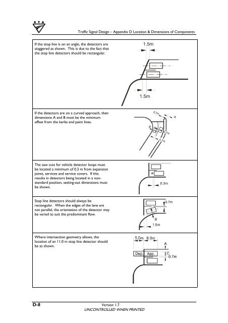
Traffic Signal Design – <strong>Appendix</strong> D <strong>Location</strong> & Dimensions <strong>of</strong> Components<br />
If the stop line is on an angle, the detectors are<br />
staggered as shown. This is due to the fact that<br />
the stop line detectors should be rectangular.<br />
If the detectors are on a curved approach, then<br />
<strong>dimensions</strong> A <strong>and</strong> B must be the minimum<br />
<strong>of</strong>fset from the kerbs <strong>and</strong> paint lines.<br />
The saw cuts for vehicle detector loops must<br />
be located a minimum <strong>of</strong> 0.3 m from expansion<br />
joints, services <strong>and</strong> service covers. If this<br />
results in detectors being located in a nonst<strong>and</strong>ard<br />
position, setting-out <strong>dimensions</strong> must<br />
be shown.<br />
Stop line detectors should always be<br />
rectangular. When the edges <strong>of</strong> the lane are<br />
not parallel, the orientation <strong>of</strong> the detector may<br />
be varied to suit the predominant flow.<br />
Where intersection geometry allows, the<br />
location <strong>of</strong> an 11.0 m stop line detector should<br />
be as shown.<br />
D-8 Version 1.7<br />
UNCONTROLLED WHEN PRINTED