Wind Load Analysis - CPP
Wind Load Analysis - CPP
Wind Load Analysis - CPP

You also want an ePaper? Increase the reach of your titles
YUMPU automatically turns print PDFs into web optimized ePapers that Google loves.
<strong>Wind</strong> <strong>Load</strong> <strong>Analysis</strong><br />
coefficient. The most challenging part to estimating<br />
wind loads on any structure is finding out<br />
which of the many pressure coefficients in ASCE<br />
7-05 should be used. The pressure coefficient<br />
depends on many factors, including the shape of<br />
the structure and the tributary area of the structural<br />
component being analyzed.<br />
Your firsthand experience with the force of the<br />
wind provides some understanding of what makes<br />
an object more or less aerodynamic. The evolution<br />
of the geometrical shape of cars, the curve of airplane<br />
wings, and the tuck of bicyclists and skiers<br />
has largely focused on improving aerodynamics so<br />
that these objects can move through the air with<br />
less resistance. This improvement is measured as a<br />
reduction in the pressure coefficient.<br />
Since force is equal to pressure times the area<br />
over which the pressure is applied, wind force is<br />
determined by multiplying the wind pressure by<br />
a representative area. This area is referred to by<br />
structural engineers as a tributary area and by<br />
ASCE as the effective wind area; see the definition<br />
in Section 6.2 of ASCE 7-05.<br />
The tributary area or effective wind area is generally<br />
understood as the area that a component structurally supports.<br />
For example, if there are four fasteners securing a<br />
4-foot-by-8-foot sheet of plywood to a roof deck, each fastener<br />
has a tributary area equal to the total area of the plywood<br />
divided by the number of fasteners, or 8 square feet.<br />
The effective wind area can also be thought of as the area<br />
over which loads are transmitted and effectively resisted by<br />
the structural system. For PV systems, one way to think of the<br />
effective wind area is this: Suppose the PV array was placed<br />
on a surface without physically restraining the system from<br />
uplift. If one were to lift one PV module in the array, how<br />
much of the system would lift along with it without permanently<br />
damaging any of the components?<br />
More than one effective wind area applies to most PV systems,<br />
depending upon the component under analysis. When<br />
analyzing the racking structure, the effective wind area may be<br />
relatively large—perhaps the area of 5 to 30 modules if the rack<br />
is rigid enough to support the applied loads from this many<br />
modules. However, the fasteners that secure the module to the<br />
rack have a smaller effective wind area. If one PV module is<br />
secured with four fasteners, each fastener has an effective wind<br />
area of one-quarter of the module area. The PV module itself<br />
has an effective wind area equal to the module area.<br />
Components with smaller effective wind areas have<br />
higher wind pressures. This is because wind pressure distributions<br />
on structures vary rapidly with time and location<br />
on the structure. One PV module may be subjected to<br />
a high wind pressure while a module 4 feet away may have<br />
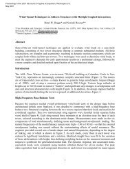
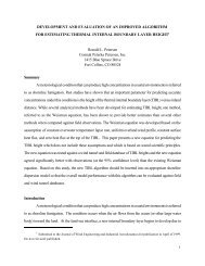
Figure 1 The conical vortices and accelerated flow region associated<br />
with oblique or cornering winds are shown here. The accelerated wind<br />
speeds between the vortices may result in actual wind pressures in<br />
excess of those calculated using typical ASCE 7 methods.<br />
a much lower wind pressure. A rigid rack supporting both<br />
modules may be able to spread the load across the structural<br />
components. However, load sharing across individual PV<br />
modules is limited, and the fasteners that secure modules<br />
to the structure cannot spread loads. Similarly, a PV mounting<br />
system that is insufficiently rigid will not spread loads<br />
over a large area. It is very important to analyze wind loads<br />
on individual PV modules using the effective wind area for<br />
one PV module to ensure that wind loads do not exceed the<br />
module’s rating. There are applications where wind loads in<br />
excess of module ratings are a very real possibility.<br />
As shown in Equation 1 (p. 76), wind force and pressure<br />
on any object is proportional to the wind velocity squared.<br />
Therefore, a wind speed of 60 mph creates wind forces<br />
four times larger than a 30-mph wind. This is important to<br />
remember when considering claims that a product can withstand<br />
a 90- or 120-mph wind speed simply because it survived<br />
a 70- or 80-mph wind event.<br />
In addition, it should be noted that the basic wind speed<br />
provided in the ASCE 7-05 standard for any location in the<br />
US represents the free-stream velocity, which corresponds<br />
with unobstructed flow over open Exposure C terrain (as<br />
defined in ASCE 7-05) at 10 meters above the ground with an<br />
averaging period of 3 seconds. Further, the basic wind speed<br />
values in ASCE 7-05 represent the expected wind speed with<br />
a 50-year recurrence interval.<br />
When you compare ASCE 7-05 wind speeds to measurements<br />
made in the field, be sure that you are comparing<br />
apples to apples. <strong>Wind</strong> sensors placed within an array at<br />
Courtesy <strong>CPP</strong><br />
78 SolarPro | June/July 2012