Acoustic Microscopy.pdf
Acoustic Microscopy.pdf
Acoustic Microscopy.pdf

You also want an ePaper? Increase the reach of your titles
YUMPU automatically turns print PDFs into web optimized ePapers that Google loves.
<strong>Acoustic</strong> <strong>Microscopy</strong><br />
A. History: The acoustic microscope was developed as a tool for studying the internal<br />
microstructure of nontransparent solids or biological materials. In acoustic microscopy,<br />
a sample is imaged by ultrasound waves, and the contrast in reflection furnishes a map<br />
of the spatial distribution of the mechanical properties. Several books and handbook<br />
articles give detailed historical outlines. Briefly, the development of the first<br />
high-frequency scanning acoustic microscope was motivated by the idea of using an<br />
acoustic field to study the spatial variations of the elastic material properties with nearly<br />
optical resolution (The lateral resolution of SAM is dependent on the frequency of the<br />
acoustic waves and, at best, is about 0.75 microns). The first experiments date back to<br />
the 1940's when high-frequency acoustic images were obtained by the Leningrad<br />
scientist Sokolov (Sokolov, S., Doklady Akademia Nauk SSSR, 64, 333, 1949). He<br />
observed an acoustical image using the tube named after him, in which the acoustic<br />
picture was converted into a television display. The first scanning acoustic microscope<br />
was created by Lemons and Quate at Stanford University in 1973 (Lemons, Quate,<br />
Appl. Phys. Lett., 24, 163, 1974). It was mechanically driven and operated in the<br />
transmission mode. Since then, gradual mechanical and electronic circuit improvements<br />
have been made and image recording has been automated. In general, acoustic<br />
microscopes now work in the reflection mode.
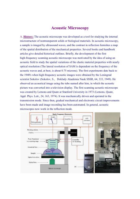
Left: The schematic diagram of the combined optical and acoustic microscope (Weiss,<br />
Lemor et al., IEEE Trans. Ultrason. Ferroelectr. Freq. Contr., 54 2257, 2007).Right: A<br />
photograph of the combined optical (Olympus IX81) and time-resolved scanning<br />
acoustic microscope, SASAM, Fraunhofer-Institute for Biomedical Technology, St.<br />
Ingbert, Germany.<br />
B. Principles: The scanning acoustic microscope (SAM) can be characterized by a<br />
combination of operating principles distinguishing it from other microscope types<br />
(Zinin Weise, “Theory and applications of acoustic microscopy”. in T. Kundu ed.,<br />
Ultrasonic Nondestructive Evaluation: Engineering and Biological Material<br />
Characterization. CRC Press, 654-724, 2004). These principles are (a) image generation<br />
by scanning, (b) far-field wave imaging, and (c) the use of acoustic waves. Image<br />
generation by scanning is basically different from the functionality of a conventional<br />
optical microscope which is the oldest microscope type. The conventional microscope<br />
can be considered a parallel processing system in which we can see all points of the<br />
object at the same time. In contrast to this, the scanning acoustic microscope is a<br />
sequential imaging system in which a piezoelectric transducer emits a focussed<br />
ultrasound beam that propagates through a water, to the sample. The beam is scattered<br />
by the sample, and the scattered ultrasound wave is detected piezoelectrically. The<br />
output signal is just one single voltage. As the sample is scanned, the voltage is<br />
recorded in each scanning position of the focus and a grey-scale image is generated. The<br />
use of a focussed beam leads to the second operating principle. As the focus is formed<br />
by converging propagating waves, the size of the focal spot (or focal area) is limited by<br />
diffraction. Imaging with ultrasound is the third operating principle. The operating<br />
frequencies of SAMs are between 100 MHz and 2 GHz; the high frequency provides the<br />
opportunity to obtain accurate measurement results for crack and void distributions with<br />
a resolution of up to 1 µm at a depth of 10 µm. Images made by the SAM are called<br />
C-scans. They are obtained when the acoustic microscope mechanically scans sample in<br />
a plane parallel to the sample surface Variation of the mechanical properties with depth
can be studied by scanning at various defocus values. Collecting images obtained at<br />
various defocus positions allows a three-dimensional image to be constructed,<br />
representing the volume of the entire microstructure of the investigated sample.<br />
Time-resolved acoustic microscopy adds an additional degree of freedom for<br />
quantitative measurement, namely time. In time-resolved acoustic microscopy a short<br />
sound pulse is sent toward a sample (for instance biological cell). The setup for<br />
quantitative time-resolved acoustic microscopy: t 0 is the arrival time of the echo<br />
reflected from the glass substrate outside the cell ("reference echo"), t 1 is the arrival<br />
time of the echo reflected from the surface of the sample (surface echo), t 2 is the arrival<br />
time of the echo reflected off the sample/substrate interface (bottom echo), and d is the<br />
sample thickness. For layered materials the reflected signal represents a train of pulses<br />
(A-scan). The time delay of the pulses and their amplitudes provides information about<br />
the elastic properties and attenuation of sound in the layer. The velocity of the wave can<br />
be determined by measuring the time delay of the corresponding pulse. Time resolved<br />
images obtained by mechanical scanning along a line are called B-scans.<br />
C. Development: Considerable progress in the acoustic microscopy of solid structures<br />
has been made since then (Briggs, A. <strong>Acoustic</strong> <strong>Microscopy</strong>, 1992, Zinin, "Quantitative<br />
<strong>Acoustic</strong> <strong>Microscopy</strong> of Solids", in Handbook of Elastic Properties of Solids, Liquids,<br />
and Gases. Volume I, Levy et al., eds. 2001, 187). Considerable progress in the acoustic<br />
microscopy of solid structures has been made since then. Developments in the theory of<br />
the image formation of subsurface defects (Lobkis et al. 1995) and three-dimensional<br />
objects (Zinin, Weise et al., Wave Motion, 25, 213, 1997) allow size and location of<br />
objects inside solids to be determined. Conventionally, SAM images show variations of
the amplitude of the acoustical signal. Reinholdtsen and Khuri-Yakub (Reinholdtsen,<br />
Khuri-Yakub, IEEE Trans. Ultrason. Ferroelect. Freq. Contr. 38, 141, 1991) measured<br />
amplitude and phase of the SAM signal at low frequency (3 to 10 MHz) to improve<br />
subsurface images. Grill extended this technique to high (1.2 GHz) frequency . This<br />
technique permits reconstruction of the surface relief of the sample with submicron<br />
resolution (Grill, Hillmann, et al., Advances in <strong>Acoustic</strong> <strong>Microscopy</strong>. Briggs, Arnold,<br />
eds. vol. II: 167, 1996). Combining the time-of-flight technique with acoustic<br />
microscopy provides a powerful tool for investigating adhesion problems as well as the<br />
microstructure of small superhard samples. An important step has been made in the<br />
direction of imaging subsurface structures at high temperatures. Ihara et al.(Ihara, Jen,<br />
France, Rev. Sci. Instrum., 71, 3579, 2000) developed a sound imaging technique to see<br />
a small steel object immerged in molten zinc at 600 o C. With the development of the<br />
ultrasonic force microscope ( Kolosov, Yamanaka, Jap. J. Appl. Phys. 32, L1095, 1993)<br />
and the atomic force acoustic microscope (Rabe, Arnold, Annalen Der Physik 3, 589,<br />
1994) the capability of the conventional acoustic microscope has been expanded to<br />
nanometer resolution.<br />
Application of SAM in Materials (Natural and Artificial) Science<br />
• Measuring the elastic properties solids and thin films<br />
• Measurement and visualization of adhesion in layered structures.<br />
• Subsurface imaging: the most common application of the acoustic microscope<br />
is the detection of subsurface defects in coatings.<br />
• Visualization of stress inside solid materials (Drescherkrasicka, Willis. Nature<br />
384, 52, 1996).<br />
• Characterization of carbon-fiber-reinforced composites (Manghnani, Zinin, et<br />
al., <strong>Acoustic</strong>al Imaging, Vol. 27, 83, 2004).
<strong>Acoustic</strong> (left) and SEM (right) images of concrete sample made with granitic aggregate<br />
grains and Portland cement paste. The acoustic image was made at 400 MHz.<br />
Application of SAM for Elastic Characterization of Biological Cells<br />
Mechanical characterization of biological cells and tissue cytoplasm by a conventional<br />
acoustic microscope was discussed thoroughly in the following review: Bereiter-Hahn,<br />
Blase, Ultrasonic Characterization of Biological Cells, in T. Kundu ed., Ultrasonic<br />
Nondestructive Evaluation: 722, 2004. Recently, a new high-frequency (1 GHz)<br />
time-resolved acoustic microscope was developed at the Fraunhofer-Institute for<br />
Biomedical Technology, St. Ingbert, Germany (Weiss, Lemor et al., IEEE Trans.<br />
Ultrason. Ferroelectr. Freq. Contr., 54 2257, 2007). It is based on an optical microscope<br />
from Olympus and it operates in a reflection mode. The design of the new microscope is<br />
different from that of conventional acoustical microscopes in that it has a modular<br />
structure. The microscope consists of four main modules: acoustical lens; optical<br />
module; scanning unit; and high-frequency electronics. This new microscope can be<br />
characterized by a combination of operating principles and design features<br />
distinguishing it from other high-frequency acoustic microscopes. These principles are:<br />
(a) it operates in time-resolved mode; (b) it is designed as an attachment to an inverse
optical microscope; (c) it is fully automated ; (d) measurements can be done at 37oC.<br />
Such a combination is of importance for studying dynamical processes in biological<br />
cells and temperature sensitive materials. This microscope enables us to measure<br />
acoustical properties of a single HeLa cell in vivo and to derive elastic parameters of<br />
subcellular structures.<br />
From IEEE Trans. Ultrason. Ferroelectr. Freq. Contr., 54 2257, 2007, Ultrasound<br />
Med. Biol. 33, 1320, 2007.<br />
References<br />
1. A. Briggs, <strong>Acoustic</strong> <strong>Microscopy</strong> Clarendon Press, Oxford, 1992<br />
2. P. V. Zinin, "Quantitative <strong>Acoustic</strong> <strong>Microscopy</strong> of Solids", in M. Levy, H. Bass,<br />
R. Stern, V. Keppens eds., Handbook of Elastic Properties of Solids, Liquids,<br />
and Gases. Vol. I: Dynamical Methods for Measuring the Elastic Properties of<br />
Solids, Academic Press, New York, 187-226 (2001).<br />
3. P. V. Zinin, "Quantitative <strong>Acoustic</strong> <strong>Microscopy</strong>". in M. Levy, H. E. Bass eds.,<br />
Experimental Methods in the Physical Sciences, Vol. 39: Modern <strong>Acoustic</strong>al<br />
Techniques for the Measurement of Mechanical Properties. Academic Press,<br />
New York, 135-187 (2001).<br />
4. P. Zinin and W. Weise, "Theory and applications of acoustic microscopy", in T.
Kundu ed., Ultrasonic Nondestructive Evaluation: Engineering and Biological<br />
Material Characterization. CRC Press, Boca Raton, chapter 11, 654-724 (2004).<br />
5. A.Briggs, (ed.), Advances in <strong>Acoustic</strong> <strong>Microscopy</strong>, Plenum Press, New York,<br />
1995, pp. 153-208.<br />
6. A. Briggs, W. Arnold eds), Advances in <strong>Acoustic</strong> <strong>Microscopy</strong> Plenum Press,<br />
New York, 1996.