AM Transmitter Module QAMT2-XXX Features Applications ... - Farnell
AM Transmitter Module QAMT2-XXX Features Applications ... - Farnell
AM Transmitter Module QAMT2-XXX Features Applications ... - Farnell

Create successful ePaper yourself
Turn your PDF publications into a flip-book with our unique Google optimized e-Paper software.
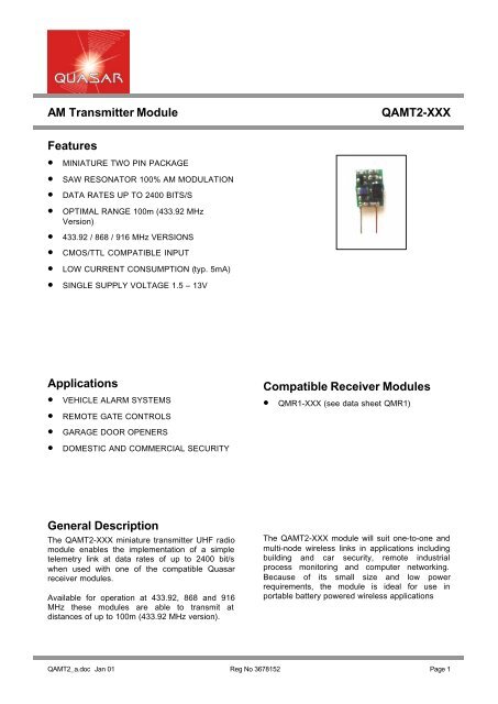
<strong>AM</strong> <strong>Transmitter</strong> <strong>Module</strong><br />
Q<strong>AM</strong>T2-<strong>XXX</strong><br />
<strong>Features</strong><br />
• MINIATURE TWO PIN PACKAGE<br />
• SAW RESONATOR 100% <strong>AM</strong> MODULATION<br />
• DATA RATES UP TO 2400 BITS/S<br />
• OPTIMAL RANGE 100m (433.92 MHz<br />
Version)<br />
• 433.92 / 868 / 916 MHz VERSIONS<br />
• CMOS/TTL COMPATIBLE INPUT<br />
• LOW CURRENT CONSUMPTION (typ. 5mA)<br />
• SINGLE SUPPLY VOLTAGE 1.5 – 13V<br />
<strong>Applications</strong><br />
• VEHICLE ALARM SYSTEMS<br />
• REMOTE GATE CONTROLS<br />
• GARAGE DOOR OPENERS<br />
• DOMESTIC AND COMMERCIAL SECURITY<br />
Compatible Receiver <strong>Module</strong>s<br />
• QMR1-<strong>XXX</strong> (see data sheet QMR1)<br />
General Description<br />
The Q<strong>AM</strong>T2-<strong>XXX</strong> miniature transmitter UHF radio<br />
module enables the implementation of a simple<br />
telemetry link at data rates of up to 2400 bit/s<br />
when used with one of the compatible Quasar<br />
receiver modules.<br />
Available for operation at 433.92, 868 and 916<br />
MHz these modules are able to transmit at<br />
distances of up to 100m (433.92 MHz version).<br />
The Q<strong>AM</strong>T2-<strong>XXX</strong> module will suit one-to-one and<br />
multi-node wireless links in applications including<br />
building and car security, remote industrial<br />
process monitoring and computer networking.<br />
Because of its small size and low power<br />
requirements, the module is ideal for use in<br />
portable battery powered wireless applications<br />
Q<strong>AM</strong>T2_a.doc Jan 01 Reg No 3678152 Page 1
<strong>AM</strong> <strong>Transmitter</strong> <strong>Module</strong><br />
Q<strong>AM</strong>T2-<strong>XXX</strong><br />
Absolute Maximum Ratings: <strong>Transmitter</strong><br />
Operating temperature:<br />
-20°C to +55°C<br />
Storage temperature:<br />
-40°C to +85°C<br />
Supply Voltage (pin 1)<br />
Data input (pin 1)<br />
15V<br />
15V<br />
Electrical Characteristics: <strong>Transmitter</strong><br />
pin min. typ. max. units notes<br />
DC LEVELS<br />
Supply voltage 1.5 5.0 13 Volts<br />
Current & RF POWER<br />
Supply current @ Rd = 1KΩ (data high) 6 8.2 9 mA<br />
RF power into 50Ω @ Rd = 1KΩ -8 -5 -3 dBm<br />
Supply current @ Rd = 100Ω (data high) 4 7 mA<br />
RF power into 50Ω @ Rd = 100Ω -10 -6 dBm<br />
RF & Data<br />
Data rate 100 2400 bits/s<br />
Data pulse width 400 µs<br />
Q<strong>AM</strong>T2_a.doc Jan 01 Reg No 3678152 Page 2
<strong>AM</strong> <strong>Transmitter</strong> <strong>Module</strong><br />
Q<strong>AM</strong>T2-<strong>XXX</strong><br />
Connection Details<br />
Application Information<br />
Component<br />
Side<br />
Quasar<br />
<strong>AM</strong><br />
<strong>Transmitter</strong><br />
Antenna Design<br />
The design and positioning of the antenna is as<br />
crucial as the module performance itself in<br />
achieving a good wireless system range. The<br />
following will assist the designer in maximising<br />
system performance.<br />
1 2<br />
Figure 1: Quasar <strong>AM</strong> <strong>Transmitter</strong><br />
The antenna should be kept as far away from<br />
sources of electrical interference as physically<br />
possible. If necessary, additional power line<br />
decoupling capacitors should be placed close to<br />
the module.<br />
Pin Description<br />
Data (pin 1)<br />
CMOS/TTL compatible input. Must be driven with<br />
appropriate current limiting resistor to provide the<br />
module with 5mA.<br />
GND (pin2)<br />
Ground connection, preferably connected to a<br />
solid ground plane.<br />
General Information<br />
The Q<strong>AM</strong>T2-<strong>XXX</strong> requires a current limiting<br />
resistor (Rd) to source the module with the correct<br />
drive current. The following values of Rd must be<br />
used with the module depending on the drive<br />
voltage:<br />
Drive Voltage = 1.5 –3.7V then Rd = 51Ω<br />
Drive Voltage = 7 – 13 V then Rd = 1K5Ω<br />
For other values of Drive Voltage:<br />
The antenna ‘hot end’ should be kept clear of any<br />
objects, especially any metal as this can severely<br />
restrict the efficiency of the antenna to receive<br />
power. Any earth planes restricting the radiation<br />
path to the antenna will also have the same effect.<br />
Best range is achieved with either a straight piece<br />
of wire, rod or PCB track @ ¼ wavelength<br />
(15.5cm @ 433.92MHz). Further range may be<br />
achieved if the ¼ wave antenna is placed<br />
perpendicular in the middle of a solid earth plane<br />
measuring at least 16cm radius. In this case, the<br />
antenna should be connected to the module via<br />
some 50 ohm characteristic impedance coax.<br />
Loop Antenna<br />
PIN 1<br />
Loop Antenna Area<br />
600mm 2<br />
Drive Voltage<br />
Rd =<br />
5mA<br />
PIN 2<br />
C1<br />
Signal From<br />
Encoder<br />
drive current<br />
Rd<br />
ANTENNA<br />
C1 = 2.2pF @ 418MHz<br />
C1 = 1pF @ 433MHz<br />
C1 = 1pF @ 868MHz and halve loop area<br />
1 2<br />
Q<strong>AM</strong>T2<br />
drive<br />
voltage<br />
250pF<br />
Whip Antenna<br />
PIN 1<br />
15.5cm @ 433MHz<br />
.<br />
Figure 2: Drive Circuit Required For Quasar<br />
<strong>AM</strong> <strong>Transmitter</strong> <strong>Module</strong><br />
Figure 3: Antenna Configurations To Be Used<br />
With The Quasar <strong>AM</strong> <strong>Transmitter</strong> <strong>Module</strong><br />
Q<strong>AM</strong>T2_a.doc Jan 01 Reg No 3678152 Page 3
<strong>AM</strong> <strong>Transmitter</strong> <strong>Module</strong><br />
Q<strong>AM</strong>T2-<strong>XXX</strong><br />
Mechanical Dimensions<br />
10mm<br />
3.5mm<br />
14mm<br />
Quasar<br />
<strong>AM</strong><br />
<strong>Transmitter</strong><br />
1 2<br />
5.08mm<br />
Figure 4: Quasar <strong>AM</strong> <strong>Transmitter</strong><br />
Ordering Information<br />
Standard Product;<br />
Part No<br />
Q<strong>AM</strong>T2-434<br />
Q<strong>AM</strong>T2-868<br />
Q<strong>AM</strong>T2-916<br />
Description<br />
<strong>AM</strong> Two Pin <strong>Transmitter</strong> 434MHz<br />
<strong>AM</strong> Two Pin <strong>Transmitter</strong> 868MHz<br />
<strong>AM</strong> Two Pin <strong>Transmitter</strong> 916MHz<br />
Quasar Ltd<br />
Unit 21 Cliffe Industrial Estate, Lewes<br />
East Sussex, BN8 6JL<br />
Tel: +44 (0) 870 240 2243<br />
Fax: +44 (0) 870 240 2239<br />
Email: sales@quasar-ltd.com<br />
Web Site: http://www.quasar-ltd.com<br />
Q<strong>AM</strong>T2_a.doc Jan 01 Reg No 3678152 Page 4