NASA SP-413 Space Settlements - Saint Ann's School
NASA SP-413 Space Settlements - Saint Ann's School
NASA SP-413 Space Settlements - Saint Ann's School

Create successful ePaper yourself
Turn your PDF publications into a flip-book with our unique Google optimized e-Paper software.
<strong>NASA</strong> <strong>SP</strong>-<strong>413</strong> — <strong>SP</strong>ACE SETTLEMENTS — A Design Study<br />
109<br />
Track Alignment<br />
Three methods of track alignment might be considered.<br />
1. Optical reticles viewed with a telescope. If the<br />
instrument is diffraction-limited at 1-m aperture,<br />
resolution is 10 -6 rad, or 10 -3 m at a distance of 1 km.<br />
By elevating reticles to account for lunar surface<br />
curvature the track may be initially aligned along the<br />
lunar surface.<br />
2. Accelerometry. A bucket may be instrumented with<br />
recording accelerometers and made to traverse the track<br />
by coasting at high velocity, for example, 10 3 m/s,<br />
without acceleration. Track misalignments thus show<br />
up with high resolution.<br />
3. Zone-plate alignment. This is the system used in the<br />
LINAC at the Stanford Linear Accelerator. Fresnel<br />
zone plates are used to focus a laser beam to a point;<br />
photodetectors locate the point and scan across it. The<br />
derivative of the luminous intensity across the point is<br />
found automatically and used to define reproducibly the<br />
center of the point, to an accuracy of 25 m.<br />
Launch Sequence<br />
The launch sequence as a bucket proceeds along the track<br />
might be described as follows:<br />
1. Coarse acceleration — 10 km at 288 m/s 2 . The track<br />
may be coarse-aligned since larger oscillations are<br />
permitted than are tolerable prior to release. The<br />
velocity is measured along the track in real time using<br />
laser doppler; an integration time of 5 X 10 -5 s gives<br />
velocity accurate to 2 X 10 -2 m/s. In this time the<br />
velocity change due to acceleration is 1.5 X 10 -2 m/s so<br />
that velocity at cutoff of the acceleration may be made<br />
accurate to better than 3 X 10 -2 m/s.<br />
2. Fine acceleration — 1 km at 1 m/s 2 . The track must be<br />
fine-aligned. Laser doppler integration time is 10 -3 s;<br />
accuracy is 10 -3 m/s; velocity change in this time is 10 -3<br />
m/s. The velocity cutoff is accurate to approximately<br />
this value, biased slightly above the desired velocity.<br />
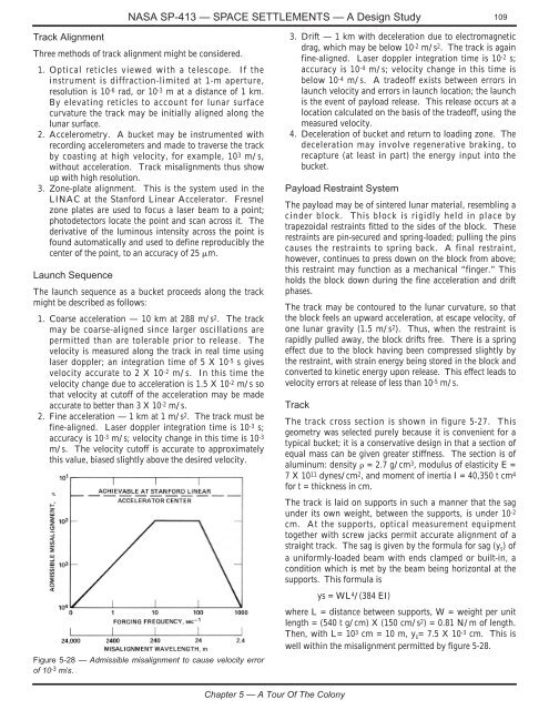
Figure 5-28 — Admissible misalignment to cause velocity error<br />
of 10 -3 m/s.<br />
3. Drift — 1 km with deceleration due to electromagnetic<br />
drag, which may be below 10 -2 m/s 2 . The track is again<br />
fine-aligned. Laser doppler integration time is 10 -2 s;<br />
accuracy is 10 -4 m/s; velocity change in this time is<br />
below 10 -4 m/s. A tradeoff exists between errors in<br />
launch velocity and errors in launch location; the launch<br />
is the event of payload release. This release occurs at a<br />
location calculated on the basis of the tradeoff, using the<br />
measured velocity.<br />
4. Deceleration of bucket and return to loading zone. The<br />
deceleration may involve regenerative braking, to<br />
recapture (at least in part) the energy input into the<br />
bucket.<br />
Payload Restraint System<br />
The payload may be of sintered lunar material, resembling a<br />
cinder block. This block is rigidly held in place by<br />
trapezoidal restraints fitted to the sides of the block. These<br />
restraints are pin-secured and spring-loaded; pulling the pins<br />
causes the restraints to spring back. A final restraint,<br />
however, continues to press down on the block from above;<br />
this restraint may function as a mechanical “finger.” This<br />
holds the block down during the fine acceleration and drift<br />
phases.<br />
The track may be contoured to the lunar curvature, so that<br />
the block feels an upward acceleration, at escape velocity, of<br />
one lunar gravity (1.5 m/s 2 ). Thus, when the restraint is<br />
rapidly pulled away, the block drifts free. There is a spring<br />
effect due to the block having been compressed slightly by<br />
the restraint, with strain energy being stored in the block and<br />
converted to kinetic energy upon release. This effect leads to<br />
velocity errors at release of less than 10 -5 m/s.<br />
Track<br />
The track cross section is shown in figure 5-27. This<br />
geometry was selected purely because it is convenient for a<br />
typical bucket; it is a conservative design in that a section of<br />
equal mass can be given greater stiffness. The section is of<br />
aluminum: density = 2.7 g/cm 3 , modulus of elasticity E =<br />
7 X 10 11 dynes/cm 2 , and moment of inertia I = 40,350 t cm 4<br />
for t = thickness in cm.<br />
The track is laid on supports in such a manner that the sag<br />
under its own weight, between the supports, is under 10 -2<br />
cm. At the supports, optical measurement equipment<br />
together with screw jacks permit accurate alignment of a<br />
straight track. The sag is given by the formula for sag (y s ) of<br />
a uniformly-loaded beam with ends clamped or built-in, a<br />
condition which is met by the beam being horizontal at the<br />
supports. This formula is<br />
ys = WL 4 /(384 EI)<br />
where L = distance between supports, W = weight per unit<br />
length = (540 t g/cm) X (150 cm/s 2 ) = 0.81 N/m of length.<br />
Then, with L= 10 3 cm = 10 m, y s = 7.5 X 10 -3 cm. This is<br />
well within the misalignment permitted by figure 5-28.<br />
Chapter 5 — A Tour Of The Colony