English - Navman Marine
English - Navman Marine
English - Navman Marine

Create successful ePaper yourself
Turn your PDF publications into a flip-book with our unique Google optimized e-Paper software.
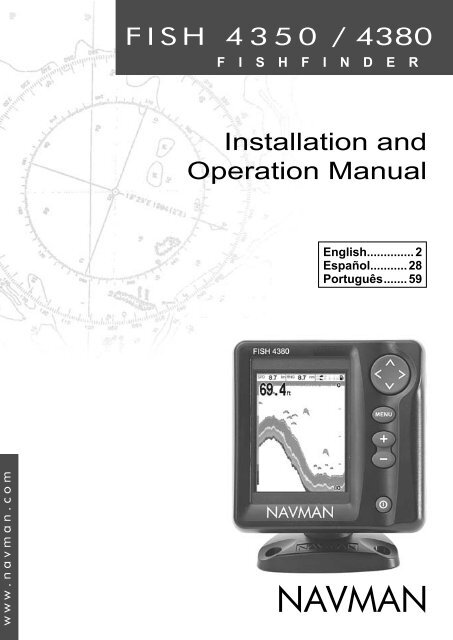
FISH 4350 / 4380<br />
F I S H F I N D E R<br />
Installation and<br />
Operation Manual<br />
<strong>English</strong>.............. 2<br />
Español........... 28<br />
Português....... 59<br />
www.navman.com<br />
NAV MAN
The FISH 4350 and FISH 4380 are set up with default units of feet, °F (Fahrenheit),<br />
US gallons and knots. See section 3-7 Setup > Units, to change the units.<br />
FCC Statement<br />
Note: This equipment has been tested and found to comply with the limits for a<br />
Class B digital device, pursuant to Part 15 of the FCC Rules. These limits are<br />
designed to provide reasonable protection against harmful interference in a normal<br />
installation. This equipment generates, uses and can radiate radio frequency<br />
energy and, if not installed and used in accordance with the instructions, may cause<br />
harmful interference to radio communications. However, there is no guarantee that<br />
interference will not occur in a particular installation. If this equipment does cause<br />
harmful interference to radio or television reception, which can be determined<br />
by turning the equipment off and on, the user is encouraged to try to correct the<br />
interference by one or more of the following measures:<br />
Reorient or relocate the receiving antenna.<br />
Increase the separation between the equipment and receiver.<br />
Connect the equipment into an output on a circuit different from that to<br />
which the receiver is connected.<br />
Consult the dealer or an experienced technician for help.<br />
A shielded cable must be used when connecting a peripheral to the<br />
serial ports.<br />
IMPORTANT<br />
It is the owner’s sole responsibility to install and use the instrument and transducers in a<br />
manner that will not cause accidents, personal injury or property damage. The user of this<br />
product is solely responsible for observing safe boating practices.<br />
NAVMAN NZ LIMITED DISCLAIMS ALL LIABILITY FOR ANY USE OF THIS PRODUCT IN A<br />
WAY THAT MAY CAUSE ACCIDENTS, DAMAGE OR THAT MAY VIOLATE THE LAW.<br />
Governing Language: This statement, any instruction manuals, user guides and other<br />
information relating to the product (Documentation) may be translated to, or has been translated<br />
from, another language (Translation). In the event of any conßict between any Translation<br />
of the Documentation, the <strong>English</strong> language version of the Documentation will be the ofÞ cial<br />
version of the Documentation.<br />
Fuel Computer: Fuel economy can alter drastically depending on the boat loading and<br />
sea conditions. The fuel computer should not be the sole source of information concerning<br />
available fuel onboard and the electronic information should be supplemented by visual or<br />
other checks of the fuel load. This is necessary due to possible operator induced errors such<br />
as forgetting to reset the fuel used when Þ lling the tank, running the engine with the fuel<br />
computer not switched on or other operator controlled actions that may render the device<br />
inaccurate. Always ensure that adequate fuel is carried onboard for the intended trip plus a<br />
reserve to allow for unforeseen circumstances.<br />
This manual represents the FISH 4350 and FISH 4380 as at the time of printing. <strong>Navman</strong> NZ<br />
Limited reserves the right to make changes to speciÞ cations without notice.<br />
Copyright © 2003 <strong>Navman</strong> NZ Limited, New Zealand. All rights reserved. <strong>Navman</strong> is a registered<br />
trademark of <strong>Navman</strong> NZ Limited.<br />
2 NAVMAN<br />
FISH 4350 / 4380 Installation and Operation Manual
Contents<br />
1 In tro duc tion.............................................................................................4<br />
1-1 BeneÞ ts of the FISH 4350 and FISH 4380..................................................... 4<br />
1-2 How the FISH 4350 and FISH 4380 work ...................................................... 4<br />
2 Basic Op er a tion......................................................................................5<br />
3 Setting up the FISH 4350 and FISH 4380..............................................7<br />
3-1 Setup > System.............................................................................................. 8<br />
3-2 Setup > Sonar ................................................................................................ 8<br />
3-3 Setup > Fuel (FISH 4380 only) ...................................................................... 9<br />
3-4 Setup > Data ................................................................................................ 10<br />
3-5 Setup > Logs.................................................................................................11<br />
3-6 Setup > Alarms..............................................................................................11<br />
3-7 Setup > Units ............................................................................................... 12<br />
3-8 Setup > Comms (FISH 4380 only) ............................................................... 12<br />
3-9 Setup > Calibrate ......................................................................................... 12<br />
4 Using the FISH 4350 and FISH 4380 ...................................................13<br />
4-1 Interpreting the display................................................................................. 13<br />
4-2 Fish detection and display............................................................................ 16<br />
4-3 Gain.............................................................................................................. 17<br />
4-4 Range........................................................................................................... 18<br />
5 The Displays .........................................................................................18<br />
5-1 Sonar display .............................................................................................. 19<br />
5-2 Sonar Zoom display ..................................................................................... 19<br />
5-3 Sonar Bottom display ................................................................................... 19<br />
5-4 Sonar A-Scope display................................................................................ 20<br />
5-5 Fuel display (FISH 4380 only)...................................................................... 20<br />
5-6 Data display ................................................................................................ 21<br />
6 Installation and Maintenance ..............................................................21<br />
6-1 What comes with this product? .................................................................... 21<br />
6-2 Options and Accessories.............................................................................. 21<br />
6-3 Mounting and removing the display unit....................................................... 21<br />
6-4 Wiring Options ............................................................................................. 22<br />
6-5 Systems of several instruments .................................................................. 23<br />
6-6 Cleaning and maintenance .......................................................................... 24<br />
Appendix A - SpeciÞcations ...................................................................24<br />
Appendix B - Troubleshooting ...............................................................25<br />
Appendix C - How to contact us ............................................................90<br />
FISH 4350 / 4380 Installation and Operation Manual NAVMAN<br />
3
1 Introduction<br />
Congratulations on choosing a <strong>Navman</strong> Þ sh-<br />
Þnder. For maximum beneÞt, please read this<br />
manual carefully before installation and use.<br />
This manual describes how to install and set<br />
up the FISH 4350 or FISH 4380. Refer to<br />
seperate Transducer Installation Instructions<br />
supplied with the transducer.<br />
1-1 BeneÞts of the FISH 4350 and FISH 4380<br />
The FISH 4350 and FISH 4380 are high quality<br />
ÞshÞnders that are supplied with a transducer.<br />
Both use TFT (Thin Film Transistor) technology<br />
to provide a colour display for easy daylight<br />
viewing. The LED backlight can be dimmed for<br />
night Þshing. The bracket mounting option also<br />
allows the ÞshÞnder to be tilted and swivelled for<br />
optimum viewing.<br />
The colours on the sonar displays are customizable,<br />
with a choice of four 16 colour<br />
palettes and one 8 colour palette. The colours<br />
represent different signal strengths, making the<br />
sonar displays easy to interpret.<br />
This capability, combined with a variable power<br />
output of up to 200 W RMS, ensures that the<br />
FISH 4350 and FISH 4380 operate effectively<br />
in shallow and deep water.<br />
The FISH 4350 and FISH 4380 can detect the<br />
bottom to a depth of 600 feet (180 metres)<br />
depending on the clarity of the water and the<br />
type of transducer used.<br />
The <strong>Navman</strong> ÞshÞnder can be used to Þnd Þsh,<br />
to locate features on the bottom such as reefs<br />
or wrecks and to help recognize favourite Þshing<br />
spots from the bottom proÞle.<br />
The <strong>Navman</strong> fishfinder can also assist with<br />
This manual also explains how to operate the<br />
FISH 4350 and FISH 4380 effectively and gives<br />
troubleshooting and performance tips.<br />
Important<br />
It is vital to the performance of the ÞshÞnder<br />
that the transducer is installed in the best<br />
location. Please follow the installation<br />
instructions very carefully.<br />
navigation by providing depth information to help<br />
identify the depth contours marked on charts.<br />
IMPORTANT NOTE ON USE. While any<br />
ÞshÞnder can be used as an aid to navigation,<br />
accuracy can be limited by many factors,<br />
including the location of the transducer. It is<br />
the user’s responsibility to ensure the <strong>Navman</strong><br />
ÞshÞnder is installed and used correctly.<br />
With the optional fuel kit, the FISH 4380 also<br />
becomes a sophisticated and easy-to-use<br />
fuel computer.<br />
All of the <strong>Navman</strong> 4000 Series fishfinders<br />
use proprietary SBN Technology for sonar<br />
processing to improve Signal enhancement,<br />
Bottom recognition and Noise rejection.<br />
SBN Technology uses digital adaptive filter<br />
algorithms to enhance all returned signals. At the<br />
same time, SBN Technology uses active noise<br />
control to reject interference, which can often be<br />
mistaken by ÞshÞnders for true returns.<br />
Using SBN Technology, the <strong>Navman</strong> ÞshÞnder<br />
analyses the reßections from each pulse, Þlters<br />
false returns and displays what is in the water<br />
under the boat. See section 4-1 Interpreting the<br />
display, for more information.<br />
1-2 How the FISH 4350 and FISH 4380 work<br />
The FISH 4350 and FISH 4380 have two parts:<br />
- the transducer attached to the hull<br />
- the display unit.<br />
The transducer generates an ultrasonic pulse<br />
(sound that is above the hearing range of the<br />
human ear), which travels down towards the<br />
bottom at a speed of about 4800 ft/sec (1500 m/<br />
sec), spreading out into a cone shape.<br />
When the pulse meets an object, such as a<br />
Þsh or the bottom, it is partly reßected back up<br />
towards the boat as an echo. The depth of the<br />
object or bottom is calculated by the FISH 4350<br />
and FISH 4380 by measuring the time taken<br />
between sending a pulse and receiving the<br />
echo. When an echo has been returned, the<br />
next pulse is sent.<br />
The FISH 4350 and FISH 4380 convert each<br />
echo into an electronic signal, displayed as a<br />
vertical line of pixels. The most recent echo<br />
appears on the extreme right of the display, with<br />
4 NAVMAN<br />
FISH 4350 / 4380 Installation and Operation Manual
the older echoes being scrolled towards the left,<br />
eventually disappearing off the display.<br />
The scroll speed depends upon the water<br />
depth and scroll speed setting. See section<br />
3-2 Setup > Sonar and section 4-1 Interpreting<br />
the display, for more information.<br />
The appearance of echoes displayed are<br />
2 Basic Operation<br />
Key Names<br />
affected by:<br />
• the Þ shÞ nder settings (range and gain<br />
settings)<br />
• echoes (different Þ sh types, different<br />
bottom types, wrecks and seaweed)<br />
• noise (water clarity and bubbles).<br />
See section 4-1 Interpreting the display, for<br />
more information.<br />
Returns to the previous menu / zooms in.<br />
, Cursor keys move the selection highlight and<br />
change settings / scrolls up or down.<br />
ConÞ rms changes / zooms out.<br />
MENU Press to show the Display menu<br />
Press again to show the Setup menu.<br />
+ Increases the Range.<br />
Hold for Auto Range<br />
_<br />
Decreases the Range.<br />
Press and hold to power On and Off; pressing<br />
once shows the Gain controls. Press twice to<br />
show Backlight control.<br />
Key Operation<br />
The Þ shÞ nder is operated through menus.<br />
To select a menu item:<br />
1. Press or to move the highlight to the<br />
item.<br />
2. Press to select the item.<br />
To change a setting:<br />
1. Use the cursor keys or to make the<br />
change(s).<br />
2. Press to conÞ rm; to cancel.<br />
Power On / Auto Power<br />
Press to turn the Þ shÞ nder on.<br />
If the Þ shÞ nder is wired for auto power, it turns<br />
on automatically whenever the boat’s ignition<br />
is turned on. This ensures that the engine<br />
hours counter and optional fuel functions are<br />
activated. A title display appears brießy. This is<br />
followed automatically by the Installation menu<br />
only the Þrst time the Þ shÞ nder is switched<br />
on. Use this menu to specify the language (see<br />
section 3-1 Setup > System) and units (see<br />
section 3-7 Setup > Units).<br />
At all other times, the title display is followed by<br />
the display that was used most recently.<br />
If the transducer is not connected, the message:<br />
No transducer detected. Enter<br />
simulate mode? will appear. Press<br />
or to select and press to accept. (If the<br />
transducer was not intentionally disconnected,<br />
turn off the ÞshÞnder and refer to the section on<br />
Troubleshooting in Appendix B.)<br />
FISH 4350 / 4380 Installation and Operation Manual NAVMAN<br />
5
Power Off<br />
To turn the Þ shÞ nder off, hold . A countdown<br />
box appears. Continue to hold for 3 seconds<br />
until the Þ shÞ nder turns off.<br />
Note: If the unit is wired for Auto Power<br />
(section 6-4 Wiring options) the Þ shÞ nder can<br />
be turned off only when the boat’s ignition is<br />
turned off.<br />
Simulate Mode<br />
An internal simulator allows<br />
users to learn how to operate<br />
the ÞshÞnder off the water.<br />
In Simulate mode the word<br />
Simulate flashes at the<br />
bottom of the display. The<br />
fishfinder generates data<br />
so that all the main displays<br />
appear to be operational.<br />
Use Setup > Simulate as follows:<br />
1. Press MENU twice to show the Setup<br />
menu.<br />
2. Highlight Simulate.<br />
3. Press to select On or Off.<br />
Gain Adjustment<br />
Gain (sensitivity)<br />
controls the amount<br />
of detail displayed on<br />
the screen. Refer to<br />
section 4-3 for more<br />
information.<br />
1. Press brieß y<br />
to show the gain<br />
controls.<br />
2. Press or to<br />
adjust gain.<br />
3. Press to switch between auto and<br />
manual gain.<br />
4. Press or MENU to conÞ rm and exit.<br />
Display Adjustment<br />
The display and<br />
keys are backlit,<br />
with a choice of 16<br />
bright-ness levels. To<br />
change the backlight<br />
level:<br />
1. Press twice to<br />
show the backlight<br />
control.<br />
2. Press to dim or<br />
to brighten.<br />
3. Press to conÞ rm.<br />
6 NAVMAN<br />
FISH 4350 / 4380 Installation and Operation Manual
3 Setting up the FISH 4350 and FISH 4380<br />
Press MENU twice to show the Setup menu, then select a particular option using the or cursor<br />
keys. (Section 2 Basic Operation, describes how to use the keys in more detail.)<br />
The Setup menu and options are summarized below. The factory default settings are shown<br />
where applicable. Each Setup menu option is explained in the following sections.<br />
The Setup menu and options<br />
System - see section 3-1 Sonar - see section 3-2<br />
Data - see section 3-4<br />
Fuel - see section 3-3<br />
Logs - see section 3-5<br />
Alarms - see section 3-6<br />
Units - see section 3-7<br />
Comms - see section 3-8<br />
Calibrate - see section 3-9<br />
Simulate - see section 2<br />
FISH 4350 / 4380 Installation and Operation Manual NAVMAN<br />
7
3-1 Setup > System<br />
Press MENU twice to display the Setup menu,<br />
then select System:<br />
Language<br />
Select the language for the displays. The<br />
options are: <strong>English</strong>, Italian, French, German,<br />
Spanish, Dutch, Swedish, Portuguese, Finnish<br />
and Greek.<br />
Tip: In case you can’t read the current<br />
language, the language setting is found at the<br />
top of the system menu.<br />
Backlight<br />
The backlight control<br />
is displayed. The bar<br />
setting represents<br />
the current level of<br />
backlighting.<br />
Key beep<br />
Enables or disables<br />
the beep when a key<br />
is pressed.<br />
Auto power off<br />
Select On to have the fishfinder power off<br />
automatically every time the boat’s ignition<br />
is switched off. This applies only if the display<br />
unit is wired for Auto Power. See section 6-4<br />
Wiring Options.<br />
Snooze Mode<br />
This power<br />
saving option<br />
slows the<br />
sounding rate<br />
(time between<br />
each ultrasonic pulse) to a user speciÞ ed<br />
interval from 5 minutes to 2 hours. The<br />
Þ shÞ nder appears to turn off, however all<br />
alarms operate normally. To return to normal<br />
operation, press any button. Ideal to be used<br />
as an anchor alarm.<br />
Factory reset<br />
This option returns all of the Þ shÞ nder settings<br />
(except the language) to the default factory<br />
settings shown in section 3 Setting up the<br />
FISH 4350 and FISH 4380.<br />
“Reset to factory defaults?” appears.<br />
Press to select Yes or No. Then press MENU<br />
or to reset and exit.<br />
3-2 Setup > Sonar<br />
Press MENU twice to display the Setup menu,<br />
then select Sonar:<br />
8 NAVMAN<br />
Scroll speed<br />
Use this to set the scroll speed on the display.<br />
There is a choice of: Very Fast, Fast, Medium,<br />
Slow and Pause. The depth of the<br />
water also affects the speed of the display.<br />
Faster scroll speeds combined with a slow boat<br />
speed (typically between 2 and 6 knots) shows the<br />
most Þsh detail. Medium or Slow scroll speeds<br />
result in sonar information being displayed over a<br />
longer period, but with less detail. See Section 4-1<br />
Interpreting the display, for more information.<br />
Fish Þlter<br />
Use this to select the minimum Þsh symbol size<br />
to be detected and displayed. There is a choice<br />
of: Small, Medium and Large.<br />
FISH 4350 / 4380 Installation and Operation Manual
Palette<br />
Use this to select a colour palette. Each colour<br />
within the palette represents a different echo<br />
strength, as shown on the sonar displays.<br />
There is a choice of Þve colour palettes: Black,<br />
Blue, White, Vivid and 8 colour. The Þrst<br />
four display more detail, whilst the 8 colour<br />
palette shows a greater distinction of signal<br />
strength between each adjacent colour. For<br />
the 16 colour palette, each colour covers 1.5<br />
dB signal range. For the 8 colour palette, each<br />
colour covers 3 dB signal range.<br />
Colour bar<br />
This shows the range of colours used for the<br />
selected colour palette.<br />
It can be switched On or Off. If switched On,<br />
it is displayed down the left hand side of all the<br />
sonar displays.<br />
Digit size<br />
Use this to change the size of the depth display<br />
on the sonar displays. There is a choice of:<br />
Small, Medium and Large.<br />
Bottom lock<br />
If Bottom lock is On, the zoom section moves<br />
so the bottom is always displayed in the zoom<br />
section, regardless of changes in depth.<br />
If Bottom lock is Off, the bottom will not be<br />
displayed in the zoom section when it is outside<br />
the range covered by the zoom bar.<br />
Using the Bottom Lock and the A-Scope<br />
features together can be a powerful aid in<br />
recognising the type of bottom.<br />
Fish symbols<br />
These appear only in the main sonar displays.<br />
3-3 Setup > Fuel (FISH 4380 only)<br />
These features<br />
can be used only<br />
when the optional<br />
single or twin engine<br />
fuel kit has<br />
been installed.<br />
Press MENU<br />
twice to display<br />
the Setup<br />
menu, then<br />
select Fuel:<br />
Fish symbols can be shown in three ways:<br />
• As a Þ sh symbol (On).<br />
• As a Þ sh symbol with the depth<br />
(On+depth). The depth is shown beside<br />
the Þ sh symbol.<br />
• Switched off (Off) so that echoes are<br />
not converted to Þ sh symbols but are<br />
displayed directly.<br />
See section 4-2 Fish detection and display, for<br />
more information about Þ sh symbols.<br />
Interference Þlter<br />
This Þlters the echo signal to reduce high-level,<br />
spiky interference, such as engine noise.<br />
It can be switched On or Off.<br />
Data header<br />
The data header can be turned On or Off.<br />
When On, it is a customizable feature that can<br />
be used to display up to 6 data items, such as<br />
boat speed or fuel used.<br />
To customize the size of the Data header,<br />
highlight Size and press . There is a choice<br />
of Small and Large.<br />
To customize the data items to be displayed:<br />
1. Highlight Data setup and press . The Data<br />
header increases in size to display all 6<br />
data Þelds. Some data Þelds may be blank.<br />
2. Use or to move from data Þeld to data<br />
Þeld.<br />
3. Press at any data Þeld to show the list of<br />
data items that can be displayed there.<br />
4. Highlight the required data item and press<br />
. The data item is immediately displayed in<br />
that data Þeld.<br />
5. Press or MENU when Þnished and the<br />
Data header resizes automatically.<br />
Warning<br />
<strong>Navman</strong> fuel kits are only suitable for petrol/<br />
gasoline engines. Fuel consumption can<br />
change drastically depending upon the<br />
boat loading and the sea conditions. Always<br />
carry adequate fuel for the journey, plus a<br />
reserve.<br />
It is recommended that the fuel tank capacity is<br />
measured by draining the fuel tank, then Þ lling<br />
it to capacity. After Þ lling, note the reading from<br />
the fuel dispenser’s gauge.<br />
Note: Beware of air pockets, especially in<br />
underß oor tanks.<br />
FISH 4350 / 4380 Installation and Operation Manual NAVMAN<br />
9
Tank full<br />
Select Tank full each time the fuel tank(s)<br />
are completely reÞ lled. When asked Are you<br />
sure? select Yes. Otherwise, the reading<br />
on the Fuel display (see section 5-5 Fuel<br />
Display) and the Low Fuel Alarm (see section<br />
3 -6 Setup > Alarms) are meaningless.<br />
Set remaining<br />
Before doing a partial reÞll of the tank or removing<br />
fuel manually from the tank (for example,<br />
by siphoning it off):<br />
1. Note the Remaining reading on the<br />
Fuel display.<br />
2. Note how much fuel is added or removed.<br />
3. Calculate how much fuel is now in the<br />
tank.<br />
4. Select Set remaining and update<br />
the reading.<br />
It is essential to do this whenever some fuel<br />
is added or removed. Otherwise, the reading<br />
on the Fuel display (see section 5-5 Fuel<br />
Display) and the Low Fuel Alarm (see section<br />
3-6 Setup > Alarms) are meaningless.<br />
Clear Used<br />
Select Clear used to set Used (the amount<br />
of fuel used) to zero. Do this to start measuring<br />
the amount of fuel used over a certain time or<br />
distance.<br />
3-4 Setup > Data<br />
Press MENU twice to display the Setup menu,<br />
then select Data:<br />
Data setup<br />
To change data items (FISH 4380 only):<br />
1. Select Data setup, and press<br />
2. Use or to move from data Þ eld to<br />
data Þ eld.<br />
When asked Are you sure? select Yes.<br />
Tank size<br />
Enter the capacity of the fuel tank.<br />
Num. engines<br />
Set the number of engines to 0, 1 or 2. If 0 is<br />
selected the fuel features are turned off.<br />
Calibrate<br />
See section 3-9 Setup > Calibrate.<br />
Flow Þlter<br />
Most engines do not draw fuel from the tank at<br />
a steady rate. To give a stable fuel ßow reading,<br />
the Þ shÞ nder calculates the ß ow value(s) by<br />
taking several measurements and averaging<br />
them. Use the Flow Þ lter to set the period over<br />
which the fuel ß ow is averaged.<br />
For twin engine installations, the fuel ß ow for<br />
each engine must be adjusted separately.<br />
The Flow Þlter can be set from 0 to 10 seconds.<br />
Use the lowest value which gives a stable ß ow.<br />
Usually a value of 5 seconds (default setting)<br />
will give a satisfactory result for two-stroke<br />
carburettor engines.<br />
This setting affects the Fuel ßow and Fuel<br />
economy reading on the Fuel display (see<br />
section 5-5. Fuel display) but it does not affect<br />
the Fuel used reading.<br />
3. Press at any data Þ eld to show the list<br />
of data items that can be displayed there.<br />
4. Highlight the required data item and press<br />
. The data item is immediately displayed<br />
in that data Þ eld.<br />
5. Press or MENU when Þ nished.<br />
Time base<br />
To change the Time base of the temperature<br />
graph, select Time base and press . Choose<br />
between 5 mins, 10 mins, 20 mins, 1 hour and<br />
2 hours and press to conÞ rm.<br />
10 NAVMAN<br />
FISH 4350 / 4380 Installation and Operation Manual
3-5 Setup > Logs<br />
Press MENU twice to display the Setup menu,<br />
then select Logs:<br />
3-6 Setup > Alarms<br />
Press MENU twice to display the Setup menu,<br />
then select Alarms:<br />
Trigger settings can be deÞned to suit the boat<br />
and individual preferences as follows:<br />
c Alarm Beeper Alarm condition is<br />
Name Cycle met when the:<br />
Too 1<br />
/5 sec depth is less than<br />
shallow the alarm trigger value<br />
Too 1<br />
/2 sec depth is greater than<br />
deep the alarm trigger value<br />
Fish 1 short echo matches the Þsh<br />
beep proÞ le selected by<br />
Þ sh Þ lter<br />
Temp. 1 /2 sec temperature equals<br />
the alarm trigger value<br />
Temp. 1 /2 sec rate of change of<br />
rate<br />
temperature equals the<br />
alarm trigger value<br />
Low 1<br />
/2 sec battery voltage is<br />
battery less than the alarm<br />
trigger value<br />
Low 1<br />
/2 sec fuel remaining equals<br />
fuel<br />
the alarm trigger value.<br />
The values can be changed independently of<br />
each other. These log values are saved when<br />
the unit is turned off.<br />
Reset trip dist (FISH 4380 only)<br />
This resets the trip distance to zero.<br />
Reset total dist (FISH 4380 only)<br />
This option resets the total distance to zero.<br />
Reset engine hours<br />
Use this option to reset the engine hours to zero.<br />
This can be useful after an engine service or to count<br />
the engine hours between service intervals.<br />
Alarms can be set (enabled) to automatically<br />
detect certain conditions, such as the water being<br />
too shallow. Alarms that are enabled are shown<br />
as black icons in the Alarm status box on the<br />
sonar displays.<br />
When an enabled alarm is triggered, the beeper<br />
sounds, an alarm message is displayed and the<br />
alarm status icon is shown in red.<br />
Press or MENU to acknowledge the alarm,<br />
stop the beeper and close the alarm window.<br />
This does not disable the alarm.<br />
Alarms automatically re-enable<br />
The Too shallow, Too Deep and Low<br />
battery alarms automatically re-enable<br />
when the value moves outside the alarm<br />
trigger setting.<br />
The Temperature alarm automatically reenables<br />
when the temperature is more than<br />
0.45°F (0.25°C) above or below the alarm<br />
trigger setting.<br />
The Temperature rate alarm automatically<br />
re-enables when the rate of temperature<br />
change falls below the trigger setting by more<br />
than 0.2°F (0.1°C) per minute.<br />
Flashing Light and/or External Beeper<br />
(FISH 4380 only)<br />
If a secondary alarm indicator is required, a ßashing<br />
light and/or external beeper can be installed.<br />
These can be positioned anywhere suitable on<br />
the boat. See section 6-4 Wiring options.<br />
FISH 4350 / 4380 Installation and Operation Manual NAVMAN<br />
11
3-7 Setup > Units<br />
Press MENU twice to display the Setup menu,<br />
then select Units:<br />
Distance<br />
Select from:<br />
• nm (nautical miles)<br />
• mi (miles)<br />
• km (kilometres)<br />
Speed<br />
Select from:<br />
• kn (knots)<br />
The default units<br />
are shown in<br />
this example.<br />
• mph (miles per hour)<br />
• kph (kilometres per hour)<br />
Depth<br />
Select from:<br />
• ft (feet)<br />
• m (metres)<br />
• fa (fathoms)<br />
Fuel<br />
Select from:<br />
• Litres<br />
• USGal (US gallons)<br />
• ImpGal (Imperial Gallons)<br />
Temperature<br />
Select either:<br />
• °F (Fahrenheit)<br />
• °C (Celsius)<br />
3-8 Setup > Comms (FISH 4380 only)<br />
Use this feature when the FISH 4380 is<br />
connected to other <strong>Navman</strong> instruments or<br />
any NMEA compatible instrument.<br />
Press MENU twice to display the Setup menu,<br />
then select Comms:<br />
3-9 Setup > Calibrate<br />
Press MENU twice to display the Setup menu,<br />
then select Calibrate:<br />
The fuel options<br />
can be calibrated<br />
only when the<br />
optional single or<br />
twin engine kit is<br />
installed on petrol/<br />
gasoline engines.<br />
Speed<br />
Calibration may be<br />
required because different hull shapes have different<br />
ß ow characteristics.<br />
Obtain an accurate measurement of the boat's<br />
speed from a GPS receiver; or by following an-<br />
NMEA<br />
NMEA is generally used with third party<br />
instruments. Select On to transmit NMEA<br />
sentences (see Appendix A - SpeciÞ cations).<br />
Otherwise, select Off.<br />
NMEA data<br />
Use this to specify which NMEA sentences will<br />
be transmitted (see Appendix A - SpeciÞcations<br />
and section 5-6 Data display, for information<br />
about how to display NMEA data).<br />
other boat travelling at a known speed; or by<br />
making a timed run over a known distance.<br />
Note: for accurate calibration:<br />
• The speed from a GPS receiver should be<br />
greater than 5 knots.<br />
• The speed from another paddlewheel transducer<br />
should be between 5 and 20 knots.<br />
• Best results are achieved in calm conditions<br />
where there is minimal current (best at high or<br />
low tide).<br />
Use the cursor keys to display the speed readout<br />
box, then increase or decrease the readout to<br />
match the independent speed value.<br />
Temperature<br />
The factory settings should be sufÞciently accu-<br />
12 NAVMAN<br />
FISH 4350 / 4380 Installation and Operation Manual
ate for normal usage. To calibrate the temperature<br />
readout, Þrst measure the water temperature<br />
with a thermometer known to be accurate.<br />
Use the cursor keys to display the temperature<br />
readout box, then increase or decrease the<br />
value to match the measured temperature. The<br />
temperature can be set from 32° to 99.9°F (0°<br />
to 37.7°C) with a resolution of 0.1° unit.<br />
To change the units between °F (Fahrenheit) or<br />
°C (Celsius), see section 3-7 Setup > Units.<br />
Fuel<br />
Calibrating the fuel usage can improve the<br />
accuracy of fuel measurements.<br />
Twin engine installations require each fuel<br />
transducer to be calibrated. This can be done<br />
at the same time with two portable tanks or at<br />
different times using one portable tank.<br />
Calibrating the fuel transducer(s) requires<br />
accurate measurement of the fuel consumption.<br />
This is best done using a small portable tank. At<br />
least 4 gallons (15 litres) of fuel should be used<br />
to ensure an accurate calibration.<br />
It is often very difÞcult to Þll underßoor tanks<br />
to the same level twice due to air pockets,<br />
so the more fuel used, the more accurate the<br />
calibration.<br />
To calibrate the fuel transducer(s), perform the<br />
following steps:<br />
1. Record the level of the fuel in the tank(s).<br />
2. Connect the portable tank(s) to the<br />
engine through the fuel transducer(s).<br />
3. Run the engine at normal cruising speed<br />
until at least 4 gallons (15 litres) of fuel<br />
has been used per engine.<br />
4. Check the actual amount of fuel used per<br />
engine by reÞ lling the portable tank(s) to<br />
4 Using the FISH 4350 and FISH 4380<br />
This section explains how to interpret the<br />
sonar displays and how Þ sh are detected and<br />
displayed.<br />
It also describes Gain and Range and shows<br />
4-1 Interpreting the display<br />
The sonar displays do not show a Þxed distance<br />
travelled by the boat; rather, they display a<br />
history, showing what has passed below the<br />
boat during a certain period of time.<br />
The history of the sonar signal displayed<br />
depends the depth of the water and the scroll<br />
speed setting.<br />
In shallow water, the echoes have a short<br />
the original level and noting the reading(s)<br />
from the fuel dispenser’s gauge.<br />
5. Select Fuel. Use or to change the<br />
reading to match that on the fuel dispenser’s<br />
gauge.<br />
6. Press when the reading is correct.<br />
Note: If the fuel calibration options appear<br />
to give erroneous readings after a while, Þ rst<br />
check that the fuel sensor has been installed<br />
correctly according to the installation instructions<br />
supplied with it, then see Appendix B<br />
- Troubleshooting.<br />
Keel Offset<br />
Keel offset is a depth correction representing the<br />
vertical distance between the depth transducer<br />
and the location from which the depth is to be<br />
measured.<br />
Enter a positive keel offset value when the<br />
transducer is located below the water surface<br />
but the total depth is required.<br />
Enter a negative keel offset value when the<br />
depth below the deepest part of the boat is<br />
required (such as the keel, the rudder or the<br />
propeller) and the transducer is located closer<br />
to the water surface.<br />
Use the cursor keys to select Keel offset,<br />
then press to display the Keel offset box.<br />
Use the or cursor keys to adjust the<br />
value.<br />
Water surface<br />
Positive<br />
Depth of transducer value<br />
Negative<br />
Transducer value<br />
Note: Boat illustrated uses a through hull transducer<br />
examples of some of the different sonar<br />
displays. Also see section 1-2 How the FISH<br />
4350 and FISH 4380 works.<br />
distance to travel between the bottom and the<br />
boat. In deep water, the history moves across<br />
the display more slowly because the echoes<br />
take longer to travel between the bottom and<br />
the boat. For example, when the scroll speed<br />
is set to Fast, at depths over 600 ft (180 m) it<br />
takes about 2 minutes for each vertical line of<br />
pixels to move across the display, whereas at<br />
FISH 4350 / 4380 Installation and Operation Manual NAVMAN<br />
13
20 ft (6 m) it takes only about 25 seconds.<br />
The scroll speed can be set by the user to<br />
display either a longer history with less Þ sh<br />
information or a shorter history with more Þsh<br />
details. See section 3-2 Setup > Sonar.<br />
If the boat is anchored, the echoes all come<br />
from the same area of bottom. This produces<br />
a ß at bottom trace on the display.<br />
The screen shot shows a typical sonar display<br />
with the Fish symbols turned Off.<br />
covered by the ultrasonic pulse is a rough<br />
cone shape and the echoes are strongest<br />
in the middle.)<br />
• Clarity of water. Particles or air in the water<br />
reduce the strength of the echo.<br />
• Composition or density of the object or<br />
bottom.<br />
Note: Planing hulls at speed produce air<br />
bubbles and turbulent water that bombard<br />
the transducer. The resulting ultrasonic noise<br />
may be picked up by the transducer and<br />
obscure the real echoes.<br />
Single Þ sh<br />
Large school<br />
of Þsh<br />
Small school<br />
of Þsh<br />
Bottom<br />
Strength of echoes<br />
The colours indicate differences in the strength<br />
of the echo. The strength varies with several<br />
factors, such as the:<br />
• Size of the Þsh, school of Þsh or other<br />
object.<br />
• Depth of the Þ sh or object.<br />
• Location of the Þ sh or object. (The area<br />
Kelp / Weed<br />
Soft bottoms<br />
such as mud,<br />
weed and<br />
sand show as<br />
narrow bands<br />
Hard<br />
bottoms<br />
such as<br />
rock or coral<br />
show as<br />
wide bands<br />
Bottom types<br />
Mud, weed and sandy bottoms tend to weaken<br />
and scatter the sonar pulse, resulting in a weak<br />
echo. Hard, rocky or coral bottoms reß ect the<br />
pulse, resulting in a strong echo. See section<br />
5-3 Sonar Bottom display.<br />
Frequency and cone width<br />
The pulse generated by the FISH 4350 and<br />
FISH 4380 transducer travels down through<br />
the water, spreading outwards to form a rough<br />
cone shape. Inside the cone, the return signals<br />
are the strongest. The cone width is dependent<br />
upon the transducer design and the frequency<br />
of the pulse: with <strong>Navman</strong>’s transom mount<br />
supplied, it is about 15°. The chart shows<br />
how the cone width varies over depth for each<br />
frequency used. Figures are approximate.<br />
Depth<br />
0<br />
50<br />
100<br />
150<br />
200<br />
250<br />
200 kHz<br />
15°<br />
13<br />
27<br />
40<br />
54<br />
67<br />
14 NAVMAN<br />
FISH 4350 / 4380 Installation and Operation Manual
Shadows<br />
Shadows are created around areas where the ultrasonic beam cannot ‘see’. These areas include hollows<br />
on the bottom or beside rocks and ledges, where the strong echoes returned off the rocks obscure the<br />
weak echoes of the Þsh and may also create a double bottom trace. See following for an example of<br />
the sonar display in such an environment. A double bottom trace is shown on the display.<br />
Example of shadows<br />
Sonar display of same area<br />
Þ sh is visible on the display<br />
Þ sh is hidden by the strong echoes off the<br />
bottom and is not shown on the display<br />
Þ sh is visible on the display<br />
<strong>Navman</strong> Þ shÞ nders display the most recent events on the right of the screen.<br />
Moving boat 1 minute ago 30 seconds ago Now<br />
When the Þ sh symbol<br />
option is on, any echo<br />
returned that Þ ts the<br />
proÞ le of a Þ sh is<br />
displayed on the screen<br />
with a Þ sh symbol.<br />
FISH 4350 / 4380 Installation and Operation Manual NAVMAN<br />
15
Stationary boat<br />
1 minute ago Now Time<br />
When a boat is stationary, all bottom echoes will come from<br />
the same small area of bottom. This will produce a ßat bottom<br />
trace on the screen.<br />
The appearance of the Sonar and Zoom screens can<br />
be changed to suit individual preferences.<br />
Note: Times indicated are for illustration only.<br />
4-2 Fish detection and display<br />
Where to Þnd Þsh<br />
Underwater features like reefs, wrecks and<br />
rocky outcrops attract Þ sh. Use the sonar to<br />
Þnd these features, then look for Þsh by passing<br />
over the feature slowly several times using the<br />
Zoom display (see section 5-2 Sonar Zoom<br />
display). If there is a current, the Þ sh will often<br />
be found downstream of the feature.<br />
When fishing with the FISH 4350 and FISH<br />
4380 with the Fish symbols Off, a weak fuzzy<br />
band may appear between the bottom trace<br />
and surface. This might indicate a thermocline<br />
- a rapid change in water temperature, such<br />
as the edge of a warm or cold current. The<br />
temperature difference can form a barrier which<br />
the Þ sh may not swim through. In fresh water,<br />
Þ sh often collect around a thermocline.<br />
Fish symbols<br />
The Þ sh symbol can be customized or<br />
switched off altogether so that the echoes<br />
are not converted to Þ sh symbols on the<br />
display. See section 3-2 Setup > Sonar. The<br />
differences between Fish symbol On and<br />
Off are:<br />
Fish symbols On<br />
Using <strong>Navman</strong>’s SBN sonar technology the<br />
ÞshÞnder analyses all echoes and eliminates<br />
most false signals and clutter so that remaining<br />
targets are most likely Þsh. Depending on the<br />
16 NAVMAN<br />
strength of<br />
the remaining<br />
echoes,<br />
they are<br />
displayed as<br />
either small,<br />
medium or<br />
large Þsh<br />
symbols<br />
- with or<br />
without<br />
depth. While<br />
the SBN<br />
processing<br />
is very<br />
sophisticated<br />
it is not foolproof - there will be times when<br />
the ÞshÞnder will not be able to differentiate<br />
between large air bubbles, rubbish containing<br />
air, Þshing ßoats etc. and Þsh.<br />
The following picture shows the Sonar display with<br />
the Fish symbol: On + depth:<br />
Fish symbol Off<br />
For experienced users this always provides the<br />
best information as every echo is displayed,<br />
whether it is surface clutter, a thermocline or<br />
a Þsh.<br />
The picture in section 4-1 Interpreting the<br />
display, shows the Sonar display with the Fish<br />
symbols Off. The Þ sh appear as arches.<br />
FISH 4350 / 4380 Installation and Operation Manual
Fish arches<br />
In good conditions and with Fish symbols Off,<br />
a Þ sh passing through the cone-shaped ultrasonic<br />
pulse is displayed as a Þ sh arch.<br />
A Þsh arch occurs when a Þsh enters the weak<br />
edge of the sonar cone, generating a weak echo<br />
that is displayed as the Þrst pixel of the Þsh arch.<br />
As the Þsh moves closer to the middle of the<br />
cone, the distance between the transducer and<br />
the Þsh reduces and the echo is displayed at<br />
progressively shallower depths, producing the<br />
start of an arch. When the Þsh passes directly beneath<br />
the middle of the cone, the echo becomes<br />
strongest and thickest. As the Þsh passes out of<br />
the middle of the cone the reverse happens with<br />
a progressively weaker and deeper echo.<br />
There are many reasons why Þsh arches may<br />
not be seen. For example:<br />
• Poor transducer installation (see Transom<br />
Transducers Installation Guide).<br />
• If the boat is anchored then Þsh will tend to<br />
show on the display as horizontal lines as<br />
they swim into and out of the transducer<br />
sonar beam. Slow speeds in deeper water<br />
give the best Þsh arch returns.<br />
• Range is important. It will be much easier<br />
to see Þsh arches when using zoom mode<br />
to concentrate on a particular section of<br />
water, rather than just displaying everything<br />
from the surface to the bottom. Zooming<br />
increases screen resolution up to 100 times.<br />
• It is difÞcult to get Þsh arches in shallow<br />
water as the transducer sonar beam is very<br />
narrow near the surface and Þsh do not stay<br />
within the beam long enough to display an<br />
arch. Several Þsh in shallow water tend to<br />
display as randomly stacked blocks of pixels.<br />
• Wave motion may result in distorted fish<br />
arches.<br />
4-3 Gain<br />
Gain (sensitivity) controls the amount of detail<br />
displayed on the FISH 4350 and FISH 4380.<br />
Understanding how to set suitable Gain settings<br />
is important for optimum performance.<br />
The <strong>Navman</strong> Þ shÞ nder has two gain modes,<br />
Auto Gain and Manual Gain. Normally the<br />
best results are obtained in Manual Gain, but<br />
practice and experience are required to obtain<br />
the optimum settings for different conditions.<br />
Therefore, the use of Auto Gain is strongly<br />
recommended when learning to use the<br />
Þ shÞ nder or when travelling at speed.<br />
• In Auto Gain, the gain adjusts<br />
automatically to compensate for water<br />
depth and clarity.<br />
• In Manual Gain, the gain can be adjusted<br />
by the user to compensate for water<br />
depth and clarity.<br />
High Gain settings may amplify the normal background<br />
noise until it appears as random pixels.<br />
Changing between Auto and Manual<br />
To change between Auto Gain and Manual<br />
Gain:<br />
1. From any Sonar display, press .<br />
2. Use the cursor key to select Auto or<br />
Manual.<br />
Adjusting Gain settings<br />
1. From any Sonar display, press .<br />
2. Use the or cursor keys to change the<br />
gain.<br />
Note: The Gain mode<br />
automatically changes<br />
to Manual Gain if the<br />
gain setting is adjusted<br />
by the user.<br />
Obtaining the best<br />
results<br />
To obtain the best<br />
detection capability for<br />
both fish and bottom<br />
we recommend the<br />
user adjusts the gain in the A-Scope display<br />
until the threshold line is just to the right of the<br />
unwanted noise:<br />
Gain<br />
Threshold<br />
line<br />
Unwanted<br />
signal<br />
Gain line<br />
FISH 4350 / 4380 Installation and Operation Manual NAVMAN<br />
17
4-4 Range<br />
Range is the vertical depth displayed on the<br />
FISH 4350 and FISH 4380.<br />
The <strong>Navman</strong> ÞshÞ nder has two range modes,<br />
Auto Range and Manual Range:<br />
• In Auto Range, the Þ shÞ nder adjusts<br />
the depth range automatically so the<br />
bottom is always shown in the lower part<br />
of the display. The use of Auto Range is<br />
recommended for normal conditions.<br />
• In Manual Range, the Þ shÞ nder shows only<br />
a selected depth range. In areas of rapidly<br />
changing bottom depth, such as the sea<br />
ß oor around pinnacles, it can be useful<br />
to prevent the display from rescaling to<br />
always show the bottom. If the bottom is<br />
deeper than the speciÞ ed depth range, it<br />
will not be shown on the display.<br />
5 The Displays<br />
Press MENU once to show the Display menu,<br />
then select a particular display using the or<br />
cursor keys then press to conÞrm. (Section<br />
2 Basic Operation, describes how to use the<br />
keys in more detail.)<br />
The Display menu<br />
Changing the Range Mode<br />
To change between Auto Range and Manual<br />
Range, hold the + or -. The Range mode is<br />
displayed at the bottom of the screen.<br />
Press the + or - key to change to increase<br />
or decrease the range to the desired depth.<br />
Values can be set between 10 ft (3 m) to 600<br />
ft (180 m).<br />
Zoom Range and Zoom Offset<br />
On the Sonar Zoom and Sonar Bottom displays,<br />
a vertical bar is shown on the far right of the<br />
display. This is the zoom bar. The zoom bar<br />
shows the zoom range; that is, the area that<br />
is magniÞed.<br />
Use the or cursor keys to adjust the<br />
zoom range.<br />
Use the or cursor keys to adjust the<br />
zoom offset.<br />
The Display menu is summarized here<br />
and each display is shown in the following<br />
sections.<br />
Most displays have an Options menu so that<br />
relevant features can be changed quickly.<br />
Full screen display of Sonar history (section 5-1)<br />
Split display with Sonar and zoomed section (section 5-2)<br />
Bottom trace displayed as ßat line in zoomed section (section 5-3)<br />
Split display with Sonar and echo strength (section 5-4)<br />
Fuel data (section 5-5)<br />
Water temperature, depth history and other boat data (section 5-6)<br />
See below.<br />
Split Ratio<br />
Use this to change the split ratio between the zoom and the sonar history sections displayed. The<br />
default split ratio is 50%.<br />
1. Highlight Split Ratio and press .<br />
A left arrow and right arrow appear on either side of the divider line.<br />
2. Use the or cursor keys to adjust<br />
Hint: Press to return to the last sonar display used. Press MENU then to return to the previously<br />
selected display. Use this to switch between two frequently used displays.<br />
Refer to Section 3-2 Setup > Sonar, for information about customizing features on the sonar<br />
displays.<br />
18 NAVMAN<br />
FISH 4350 / 4380 Installation and Operation Manual
5-1 Sonar display<br />
To show the Sonar display highlight Sonar<br />
and press :<br />
Data header, set up to show<br />
the water temperature, battery<br />
voltage (See section 3-2 Setup<br />
> Sonar)<br />
Depth (medium size digits)<br />
Colour bar<br />
This display scrolls from right (most recent<br />
echoes) to left (oldest echoes). (see section<br />
3-2 Setup > Sonar).<br />
Surface<br />
Fish symbols with depth<br />
Bottom<br />
Range<br />
5-2 Sonar Zoom display<br />
To show the Sonar Zoom display, highlight<br />
Sonar Zoom and press :<br />
Sonar history<br />
The split display shows the sonar history on the<br />
right side and the zoom section on the left.<br />
The zoom bar on the far right shows the area<br />
that is magniÞ ed in the zoom section. See<br />
section 4-4 Range, for information about<br />
adjusting the Zoom Range and Zoom Offset.<br />
Zoom bar<br />
Zoom section<br />
Divider line<br />
5-3 Sonar Bottom display<br />
To show the Sonar Bottom display, highlight<br />
Sonar Bottom and press .<br />
This shows a split display, with the sonar history<br />
on the right side and the zoom section on the<br />
left. The bottom signal is shown as a ßat trace<br />
in the centre of the zoom section.<br />
Showing the bottom as a ßat trace can make it<br />
easy to compare the echo strengths shown in the<br />
bottom signals. This can help to identify the type<br />
of bottom and objects close to the bottom.<br />
The zoom bar can only indicate the zoom range.<br />
It cannot indicate the zoom offset as this changes<br />
for each sounding displayed on the display. The<br />
zoom bar is Þxed in the middle of the display.<br />
See section 4-4 Range, for information about<br />
adjusting the Zoom Range and Zoom Offset.<br />
FISH 4350 / 4380 Installation and Operation Manual NAVMAN<br />
19
5-4 Sonar A-Scope display<br />
To show the A-Scope display, select Sonar A-<br />
Scope and press . Use this to analyse the sonar<br />
data in detail and optimize the Gain settings.<br />
Divider line<br />
between<br />
sonar<br />
history and<br />
A-Scope<br />
Gain setting<br />
(strongest<br />
echo for<br />
display)<br />
Gain threshold<br />
(weakest echo<br />
for display)<br />
The user can deÞ ne the level of the weakest<br />
and strongest echoes to be shown on the sonar<br />
5-5 Fuel display (FISH 4380 only)<br />
displays, by using the Gain setting. See section<br />
4-3 Gain, for more information.<br />
The strength of an echo at a particular depth<br />
is shown by the length of the horizontal line at<br />
that depth. A strong echo produces a long line<br />
whereas a weak echo produces a short line.<br />
Fish recognition<br />
The echo strengths shown on the A-Scope can<br />
be useful in recognising the type of Þsh. Different<br />
species of Þsh have different sizes and shapes<br />
of swim bladders. The air in the swim bladder<br />
reßects the ultrasonic pulse, so the strength of<br />
the echo varies between Þsh species according<br />
to the size and shape of the swim bladder.<br />
When fishing among a school of fish and<br />
catching them, note the Þsh species and the<br />
strength of the echo that it returns on the<br />
A-Scope. Then, when that particular echo is<br />
seen at future times on the ÞshÞnder, it is likely<br />
to be the same Þsh species.<br />
To show the Fuel display, select Fuel and<br />
press .<br />
(See section 3-3 Setup > Fuel for information<br />
about setting up the fuel values. If the number<br />
of engines is set to 0, the fuel features are<br />
turned off.)<br />
Used shows total fuel used since this was last<br />
reset with the Clear Used command.<br />
Remaining shows the amount of fuel<br />
remaining in the tank(s).<br />
Flow shows the fuel consumption per hour.<br />
For twin engine installations, the fuel ß ow for<br />
each engine is shown separately. This is useful<br />
for checking that both engines are under the<br />
same load.<br />
Economy is the distance travelled per unit of<br />
fuel used. The Þ shÞ nder calculates this from<br />
the boat speed and fuel used. The bigger this<br />
number, the better the fuel economy. Adjust<br />
the throttle and trim to achieve the best fuel<br />
economy. Note that the FISH 4380 uses a<br />
paddlewheel transducer to measure speed,<br />
used to calculate the fuel economy. Therefore,<br />
calibration of the boat speed measurement is<br />
essential for an accurate fuel economy reading.<br />
See section 3-8 Setup > Calibrate.<br />
20 NAVMAN<br />
FISH 4350 / 4380 Installation and Operation Manual
5-6 Data display<br />
To show the Data display, select Data and press . The data<br />
display shows a graph of the water temperature and depth over<br />
time and other selected data items.<br />
The graph is useful for locating warm and cold spots in<br />
the water.<br />
Refer to section 3-4 Setup > Data to change the displayed<br />
data items and temperature graph time base. To change<br />
units, refer to section 3-7 Setup > Units.<br />
time base<br />
(Select from 5 minutes to 2 hours)<br />
6 Installation and Maintenance<br />
Correct installation is critical to the performance of the FISH 4350 and FISH 4380. There are two<br />
components to install, the display unit and the transducer. It is vital to read the entire installation<br />
section of this manual before attempting to install the components.<br />
6-1 What comes with this product?<br />
Standard conÞguration:<br />
• FISH 4350 or FISH 4380 display unit<br />
• Power cable*<br />
• Mounting bracket (screws included)<br />
• Warranty registration card<br />
• This manual<br />
• Sun cover for display unit<br />
• Flush mounting kit*<br />
• Transom transducer (includes cable kit and screws)<br />
• Transom Mount Transducer Installation Manual.<br />
* denotes FISH 4380 only.<br />
6-2 Options and Accessories<br />
• TRACKER series of chartplotters<br />
• Through hull depth transducer<br />
• Through hull speed/temperature transducer*<br />
• Fuel ßow kit (single or twin engine)*<br />
• Replacement paddle wheel*<br />
• Carry bag<br />
• REPEAT 3100 (see section 6-5 Systems of<br />
several instruments).<br />
Please consult your <strong>Navman</strong> dealer for more<br />
information. * denotes FISH 4380 only<br />
Display unit<br />
Transom transducer<br />
TRACKER 5500<br />
chartplotter<br />
6-3 Mounting and removing the display unit<br />
There are two mounting arrangements:<br />
• Flush mounting requires a solid panel<br />
with access behind for wiring and mounting<br />
screws. After ß ush mounting, the FISH 4350<br />
Mounting bracket<br />
Screws<br />
Power cable<br />
Fuel ß ow kit<br />
and FISH 4380 cannot be tilted or moved<br />
after installation to reduce any unwanted<br />
glare or reß ections. Carefully select the best<br />
viewing position before installation. This<br />
FISH 4350 / 4380 Installation and Operation Manual NAVMAN<br />
21
would generally be in a shaded area.<br />
• Bracket mounting requires a panel for<br />
mounting the bracket. Ensure that the panel<br />
is not likely to deform and is not subject to<br />
excessive vibration. The bracket can be tilted<br />
and rotated so the FISH 4350 and FISH 4380<br />
can be removed after each use.<br />
Select a position where the display unit will be:<br />
• At least 4" (100 mm) away from the compass.<br />
• At least 12" (300 mm) away from any radio<br />
transmitter.<br />
• At least 4 ft (1.2 m) away from any antenna.<br />
• Easy to read by the helmsman and crew<br />
while underway.<br />
• Protected from physical damage during<br />
rough sea passages.<br />
• Easy to access the 12 V DC power source.<br />
• Convenient to route the transducer cables.<br />
Flush Mounting<br />
1. Cut a hole in the bulkhead for the display<br />
unit using the ß ush mount template.<br />
2. Drill four holes for the mounting studs using<br />
the ß ush mount template.<br />
6-4 Wiring Options<br />
The power/data cable contains 5 wires:<br />
Wire Function<br />
Black Ground (power negative)<br />
White* NMEA out<br />
Red Positive power in, 12 V DC<br />
Yellow Auto power in (connect to<br />
red wire. Positive power in, to enable<br />
Auto power).<br />
Green* External beeper or light out, switched<br />
to ground, 30 V DC 200 mA<br />
maximum.<br />
Note: The cable shield is connected to Pin 1<br />
(black wire) and does not need to be grounded.<br />
* Denotes FISH 4380 only.<br />
Warning<br />
1 Amp fuses must be positioned where<br />
shown in the wiring diagrams.<br />
Basic wiring<br />
This requires the FISH 4350 and FISH 4380 to<br />
be powered on manually with the key.<br />
Black wire: Connect this to the negative battery<br />
terminal.<br />
Red wire: Connect this to the positive battery<br />
terminal after the main switch. Fit a 1 Amp fuse<br />
as shown.<br />
Yellow wire: Connect this to the black wire.<br />
This disables the engine hours counter.<br />
22 NAVMAN<br />
3. Screw the four studs into the brass inserts<br />
in the back of the display unit.<br />
4. Sit the display unit in place and Þ t the<br />
washers and nuts to the studs.<br />
Bracket Mounting<br />
1. Fix the mounting bracket onto the boat using the<br />
three stainless steel screws. Do not overtighten<br />
the screws, as the bracket may not rotate.<br />
2. Push the display unit onto the mounting<br />
bracket and tighten it Þ rmly using the knob<br />
on the mounting bracket.<br />
3. Attach the cables.<br />
Removing the display unit<br />
The display unit can be removed after each<br />
use for protection against the environment or<br />
security reasons.<br />
When removing the display unit, ensure that<br />
the plugs left in the boat are not exposed to<br />
the elements. Push the attached dust covers<br />
over the exposed ends of the plugs. Keep the<br />
display unit in a dry clean place such as the<br />
optional <strong>Navman</strong> carry bag.<br />
Six wiring options are described in this<br />
section:<br />
• Basic wiring. This does not start the<br />
Þ shÞ nder automatically when the boat<br />
ignition is switched on and it disables the<br />
engine hours counter.<br />
• Auto power wiring. This must be used<br />
for the engine hours and fuel computer<br />
options.<br />
• Secondary Alarm wiring<br />
• NMEA wiring<br />
• Single engine fuel wiring<br />
• Twin engine fuel wiring<br />
Note: If a wire colour is not specifically<br />
mentioned, it is not used in that wiring option.<br />
Section 6-5 Systems of several instruments,<br />
describes NMEA and NavBus.<br />
Power on the ÞshÞnder manually whenever the<br />
main switch is on.<br />
Basic wiring<br />
Fuse<br />
Red<br />
Yellow<br />
Main<br />
switch<br />
Black<br />
12 V DC<br />
FISH 4350 / 4380 Installation and Operation Manual
NMEA wiring Option<br />
(FISH 4380 only)<br />
White Wire: Use this, if desired, to connect<br />
the Þ shÞ nder to other NMEA instruments such<br />
as <strong>Navman</strong>’s REPEAT 3100. (See section 6-5<br />
Systems of several instruments.)<br />
Secondary alarm wiring option<br />
(FISH 4380 only)<br />
Green Wire: Use this to connect a secondary<br />
alarm indicator such as a flashing light or<br />
external beeper with a built-in drive circuit.<br />
See the Auto power wiring diagram.<br />
If the external beeper or light requires more than<br />
200 mA total, Þ t a relay. Consult your <strong>Navman</strong><br />
dealer for more advice.<br />
Fuel kit wiring (FISH 4380 only)<br />
See the Fuel Kit Installation Guide for<br />
information about the fuel transducer cable.<br />
Wire the power cable for Auto power (as<br />
described in this section) to make sure the fuel<br />
counter starts as soon as the engine starts.<br />
For twin engine installation, a T-connector needs<br />
to be installed on the fuel transducer cable.<br />
Auto power option<br />
Black wire: Connect this to the negative<br />
battery terminal.<br />
Red wire: Connect this to the positive battery<br />
terminal after the main switch. Fit a 1 Amp fuse<br />
as shown.<br />
Yellow wire: To enable the engine hours<br />
counter and fuel counter; and to start the<br />
Þ shÞ nder automatically when the ignition is<br />
turned on, connect the yellow wire to the ignition<br />
system through a 1 Amp fuse.<br />
Note: The Þ shÞ nder cannot be turned off while<br />
the ignition is on.<br />
Auto power option<br />
To ignition system<br />
Fuse<br />
Ignition<br />
switch<br />
Main<br />
switch<br />
Fuse<br />
External Beeper<br />
or Light<br />
12 V DC<br />
White (NMEA out)<br />
Yellow<br />
Red<br />
Green<br />
Black<br />
Through hull transducers<br />
Through hull transducers are supplied wth ‘Y’ adapter cable for<br />
connection of both transducers into top socket with blue nut.<br />
Speed/Temperature through hull transducer<br />
8 pin<br />
phono<br />
6-5 Systems of several instruments<br />
Several <strong>Navman</strong> instruments can be connected<br />
together to share data.<br />
NMEA<br />
NMEA is an industry standard for marine instrument<br />
connections. Data sent by one instrument<br />
over an NMEA line can be read and displayed<br />
Through hull depth transducer<br />
by another instrument that accepts NMEA 0183<br />
Version 2. It requires dedicated connections between<br />
instruments.<br />
Please contact your <strong>Navman</strong> dealer for<br />
information on <strong>Navman</strong>’s full range of NMEA<br />
enabled instruments and connection options.<br />
REPEAT 3100:<br />
Repeater for<br />
depth, speed,<br />
water temperature<br />
and battery voltage. Accepts<br />
NavBus or NMEA data inputs<br />
from other instruments.<br />
DEPTH 2100:<br />
Depth Repeater<br />
TRACKER 5500:<br />
Colour GPS<br />
Chartplotter with<br />
worldwide coverage<br />
FISH 4350 / 4380 Installation and Operation Manual NAVMAN<br />
23
6-6 Cleaning and maintenance<br />
Clean the screen only with a damp cloth and mild<br />
detergent when dirty or covered in sea salt. Avoid<br />
abrasive cleaners, petrol or other solvents.<br />
Cover or remove a transom-mounted<br />
transducer when repainting the hull. If painting<br />
over a through hull transducer with antifouling<br />
paint, use only one coat of paint. Remove the<br />
previous coat of antifouling paint by sanding it<br />
lightly.To optimize performance, avoid walking<br />
Appendix A - SpeciÞcations<br />
Depth range<br />
• 2 ft (0.6 m) to 600 ft (180 m).<br />
Display type<br />
• TFT Colour.<br />
• Screen resolution 320 high x 240 wide<br />
(pixels).<br />
• LED multi-level backlighting.<br />
Supply voltage<br />
• 10 to 16 V DC.<br />
Supply current at 13.8 V<br />
• 300 mA min - no backlighting.<br />
• 400 mA max - full backlighting.<br />
Output power<br />
• Variable, up to 200 W RMS.<br />
Operating temperature<br />
• 32° to 122°F (0° to 50°C)<br />
Transom transducer cable length<br />
• FISH 4350 33 ft (10 m).<br />
• FISH 4380 26 ft (8 m).<br />
Typical depth acquisition time from startup<br />
• 2 seconds at 100 ft (30 m).<br />
Receiver sensitivity<br />
• Better than 10 micro volts RMS.<br />
• Dynamic range 4.0 million to 1 (120 dB).<br />
Temperature measurement range<br />
• 32° to 99.9°F (0°<br />
to 37.7°C)<br />
Resolution of<br />
0.1° unit.<br />
Transducer<br />
frequency<br />
• 200 kHz.<br />
Speed range<br />
• 1 to 50 kn (57.5<br />
mph, 96.6 kph).<br />
Standards<br />
Compliance<br />
• EMC:USA FCC<br />
Part 15 Class B.<br />
Europe (CE)<br />
EN50081-1 and<br />
EN50082-1<br />
5.7" (143.5 mm)<br />
5.0" (126.0 mm)<br />
5.0" (126.0 mm)<br />
FISH 4350: 89 mm (3.5")<br />
FISH 4380: 97 mm (3.8")<br />
on or jamming cables and connectors. Keep the<br />
transducer free of weed, paint and debris. Do not<br />
use a high pressure water blast on a speed sensor<br />
paddlewheel as it may damage the bearings.<br />
When not in use, the FISH 4350 or FISH 4380<br />
can be removed from the installation bracket and<br />
stored in the <strong>Navman</strong> carry bag, or left on the<br />
installation bracket and securely covered with<br />
the sun cover.<br />
New Zealand and Australia (C Tick)<br />
AS-NZS 3548.<br />
· Environment: IP67.<br />
NMEA Output (FISH 4380 only)<br />
NMEA 0183 (Ver 2.0) 4800 baud is a standard for<br />
interfacing marine electronic devices. The <strong>Navman</strong><br />
ÞshÞnder can output the following sentences:<br />
• DBT (Depth Below Transducer)<br />
• DPT (Depth and Keel offset)<br />
• MTW (Water temperature)<br />
• XDR (Battery voltage and fuel ß ow).<br />
• VHW (Speed)<br />
Fuel Computer (FISH 4380 only)<br />
(optional fuel transducer(s) required)<br />
• Outboard carburetted two stroke and EFI<br />
petrol/gasoline engines: 30 to 300 hp.<br />
• Outboard four stroke petrol/gasoline<br />
engines: 90 to 300 hp.<br />
• Inboard petrol/gasoline engines: 50 to 300 hp.<br />
• Minimum ß ow rate: 1.3 U.S. gallons per<br />
hour (5 litres per hour).<br />
• Maximum ß ow rate: 34 U.S. gallons per<br />
hour (130 litres per hour).<br />
1.1" (27.9 mm)<br />
1.2" (30.5 mm)<br />
FISH 4350 and FISH 4380<br />
3.5" (88.5 mm)<br />
24 NAVMAN<br />
FISH 4350 / 4380 Installation and Operation Manual
Appendix B - Troubleshooting<br />
This troubleshooting guide is written with<br />
the assumption that the user has read and<br />
understood the relevant sections in this manual.<br />
It is possible in many cases to solve difÞ culties<br />
without having to send the display unit back to<br />
the manufacturer for repair. Please follow this<br />
troubleshooting section before contacting the<br />
nearest <strong>Navman</strong> dealer.<br />
There are no user serviceable parts. Specialized<br />
methods and testing equipment are required to<br />
ensure that the display unit is reassembled<br />
correctly and is waterproof. Users who service<br />
the product themselves will void the warranty.<br />
Repairs to the product may only be carried out<br />
by a service centre approved by <strong>Navman</strong>. If the<br />
product must be sent into a service centre for<br />
repair, it is essential to send in the transducer(s)<br />
at the same time.<br />
More information can be found on our Website:<br />
www.navman.com.<br />
1. The ÞshÞnder won’t turn on:<br />
a) The FISH 4350 and FISH 4380 are<br />
designed to operate on a 12 volt battery<br />
system, where the voltage may vary from<br />
10 to 16.5 volts. If an excessive voltage is<br />
supplied, a resettable fuse will be tripped,<br />
turning the display unit off.<br />
b) Check that the power cable connector at the<br />
back of the display unit is securely plugged<br />
in and the collar is locked in place. The collar<br />
must be secure for watertight connection.<br />
c) Measure the battery voltage while the battery<br />
is under load - turn on some lights, radio or<br />
other electrical equipment connected to the<br />
battery. If the voltage is less than 10 volts:<br />
- the battery terminals or wiring on the<br />
terminals may be corroded.<br />
- the battery may not be charging<br />
correctly or may need replacing.<br />
d) Inspect the power cable from end to<br />
end for damage such as cuts, breaks,<br />
squashed or trapped sections.<br />
e) Ensure that the red wire is connected to the<br />
positive battery terminal and the black wire to<br />
the negative battery terminal. If wired for the<br />
Auto Power option, ensure the yellow wire is<br />
connected to the ignition circuit. Also check<br />
the boat’s main switch circuit (see section<br />
6-5 Wiring options).<br />
f) Check for corrosion on the power cable<br />
connector and clean or replace if required.<br />
g) Check fuses that are placed in line with the<br />
power cable. A fuse can be blown despite<br />
appearing to be good or the fuse may be<br />
corroded. Test the fuse or replace it with a<br />
fuse known to be good.<br />
2. The ÞshÞnder won’t turn off:<br />
The Þ shÞ nder may have been wired for<br />
Auto power. In this case, the fishfinder<br />
cannot be turned off while the ignition power<br />
is on. (See Auto power wiring in section 6-4<br />
Wiring options.)<br />
3. The ÞshÞnder operates erratically:<br />
a) Check that the transducer does not have<br />
debris (e.g. weed, plastic bag) caught<br />
around it.<br />
b) The transducer may have been damaged<br />
during launching, running aground or<br />
while underway with debris etc. If the<br />
transducer has been impacted, it may have<br />
been kicked up on the bracket. If it is not<br />
physically damaged, reset the transducer<br />
back to its original position. (See the<br />
Transom Transducer Installation Guide.)<br />
c) When the transducer is less that 2 ft (0.6 m)<br />
from the bottom, the depth readings may<br />
become inconsistent and erratic.<br />
d) Manual Gain may be set too low, which may<br />
cause weak bottom echo or no Þsh signals.<br />
If in Manual Gain, try increasing the Gain.<br />
e) Ensure the back of the bottom surface of the<br />
transducer is slightly lower than the front and<br />
the front is as deep in the water as possible in<br />
order to minimize the generation of bubbles<br />
through cavitation. (See the Transom<br />
Transducers Installation Guide.)<br />
f) Check the transducer and power cable<br />
connectors at the back of the display unit<br />
are securely plugged in and the collars are<br />
locked in place. The collars must be secure<br />
for watertight connection.<br />
g) Inspect the power cable from end to end for<br />
damage such as cuts, breaks, squashed or<br />
trapped sections.<br />
h) Ensure there is not another fishfinder<br />
or depth sounder turned on, which may<br />
interfere with this Þ shÞ nder.<br />
i) Electrical noise from the boat’s engine<br />
or an accessory may be interfering with<br />
the transducer(s) and/or the <strong>Navman</strong><br />
Þ shÞ nder. This may cause the Þ shÞ nder<br />
to automatically decrease the Gain unless<br />
using Manual Gain.<br />
The fishfinder thus eliminates weaker<br />
signals such as Þ sh or even the bottom<br />
from the display. This may be checked by<br />
FISH 4350 / 4380 Installation and Operation Manual NAVMAN<br />
25
switching off other instruments, accessories<br />
(e.g. bilge pump) and the motor until the<br />
offending device is located. To stop<br />
problems from electrical noise, try:<br />
- re-routing the power and transducer<br />
cable(s) away from the boat’s other<br />
electrical wiring.<br />
- routing the display unit’s power cable<br />
directly to the battery with an in-line fuse.<br />
4. Bottom is not displayed:<br />
a) The Þ shÞ nder may have Manual Range<br />
selected and the depth may be outside the<br />
range value selected. Either change the<br />
Þ shÞ nder to Auto Range or select another<br />
depth range (see section 4-4 Range).<br />
b) The depth may be outside the ÞshÞnder’s<br />
range. While in Auto Range, the display<br />
unit will display “--.-” to indicate that there is<br />
no bottom detected. A display of the bottom<br />
should reappear when in shallower water.<br />
5. The bottom is displayed too far up<br />
the screen:<br />
The Þ shÞ nder may have Manual Range<br />
selected and the selected Range value is<br />
too high for the depth. Either change the<br />
Þ shÞ nder to Auto Range or select another<br />
depth range (see section 4-4 Range).<br />
6. Bottom echo disappears or erratic<br />
digital reading while the boat is moving:<br />
a) Ensure the back of the bottom surface<br />
of the transducer is slightly lower than<br />
the front and the front is as deep in the<br />
water as possible in order to minimise the<br />
generation of bubbles through cavitation.<br />
(See the Transom Transducers Installation<br />
Guide, for more information.)<br />
b) The transducer may be in turbulent water.<br />
Air bubbles in the water disrupt the echoes<br />
returned, interfering with the Þ shÞ nder’s<br />
ability to Þ nd the bottom or other targets.<br />
This often happens when the boat is<br />
reversed. The transducer must be mounted<br />
in a smooth ß ow of water in order for the<br />
Þ shÞ nder to work at all boat speeds.<br />
c) Electrical noise from the boat’s motor<br />
can interfere with the Þ shÞ nder. Try some<br />
suppression spark plugs.<br />
7. If the ÞshÞnder beeps when turned on<br />
but nothing is displayed:<br />
The Þ shÞ nder may be operating, but the<br />
backlight settings may have been set too<br />
low. See section 2 Basic Operation, to adjust<br />
the ÞshÞnder backlight. (Press twice)<br />
8. The wrong language is displayed:<br />
See section 3-1 Setup > System.<br />
9. Fuel used or remaining seem inaccurate:<br />
a) If the engine is run while the Þ shÞ nder is<br />
powered off, the Þ shÞ nder does not record<br />
the amount of fuel used during that engine<br />
run. Consequently, the Fuel remaining<br />
value will be higher than the actual amount<br />
of fuel remaining in the tank.<br />
To avoid this problem, use the Auto Power<br />
Wiring option described in section 6-4 Wiring<br />
options. This ensures that the fishfinder<br />
powers on automatically whenever the<br />
boat’s ignition is switched on.<br />
b) In rough seas, fuel may surge back and<br />
forth through the fuel transducer, resulting in<br />
incorrect readings. Try installing a one-way<br />
valve between the fuel transducer and the<br />
fuel tank.<br />
c) The Set remaining fuel value must be<br />
reset after every refuelling (see section 3-3<br />
Setup > Fuel).<br />
d) The fuel tank may not reÞ ll to the same<br />
capacity each time due to air pockets. This is<br />
particularly noticable with underßoor tanks.<br />
e) Fuel transducers wear out over time and<br />
should be replaced after every 5000 litres<br />
of fuel.<br />
10. Flow indicates no fuel or low fuel:<br />
a) Check that the number of engines is set<br />
to 1. See section 3-3 Setup > Fuel.<br />
b) Check that the fuel cable connectors are<br />
securely plugged in and the collar is locked<br />
in place. The collar must be locked in place<br />
to give a watertight connection.<br />
c) A fuel transducer may be clogged. If so,<br />
remove the transducer from the fuel line<br />
and gently blow through it in the opposite<br />
direction to the fuel ß ow.<br />
A fuel Þ lter between the fuel transducer<br />
and the fuel tank must be installed as per<br />
the fuel installation guide. Failure to do so<br />
will void the warranty.<br />
d) Inspect the fuel cable from end to end for<br />
damage such as cuts, breaks, trapped or<br />
squashed sections.<br />
e) Check that the fuel Þ lter is clean.<br />
11. A twin engine installation shows only<br />
one ßow rate:<br />
a) Check that the number of engines is set<br />
to 2. See section 3-3 Setup > Fuel.<br />
26 NAVMAN<br />
FISH 4350 / 4380 Installation and Operation Manual
12. Erratic Fuel Flow readings:<br />
a) The fuel ß ow transducer may have been<br />
mounted too close to the fuel pump or may<br />
be subject to excessive vibration. Refer to<br />
the installation instructions supplied with the<br />
fuel transducer.<br />
b) Check for leaks in the fuel line or in the fuel<br />
pickup in the tank.<br />
c) The Flow Þlter value is not suitable for the<br />
engine. Check that the value is not set to zero,<br />
then try increasing the value until a steady ßow<br />
rate is shown. See section 3-3 Setup > Fuel.<br />
13. There is no reading for fuel economy:<br />
a) The boat must be travelling through the<br />
water to generate an Economy reading.<br />
b) Check that the paddlewheel on the transducer<br />
is spinning freely and that the two magnets in<br />
the paddlewheel are still in place.<br />
14. There is a double bottom trace<br />
displayed:<br />
a) The boat may be in an area that<br />
generates shadows. See section 4-1<br />
Interpreting the display.<br />
b) In shallow water, the echoes may bounce.<br />
Reduce the gain setting (see section 4-3<br />
Gain).<br />
c) Decrease the Range.<br />
FISH 4350 / 4380 Installation and Operation Manual NAVMAN<br />
27
Appendix D - How to contact us<br />
NORTH AMERICA<br />
<strong>Navman</strong> USA Inc.<br />
30 Sudbury Rd, Acton, MA<br />
01720.<br />
Toll Free: +1 866 628 6261<br />
Fax: +1 978 897 8264<br />
e-mail:<br />
sales@navmanusa.com<br />
web: www.navman.com<br />
AUSTRALIA<br />
<strong>Navman</strong> Australia Pty. Limited<br />
Unit 2 / 5-13 Parsons St.<br />
Rozelle, NSW 2039, Australia.<br />
Ph: +61 2 9818 8382<br />
Fax: +61 2 9818 8386<br />
e-mail: sales@navman.com.au<br />
web: www.navman.com<br />
OCEANIA<br />
New Zealand<br />
Absolute <strong>Marine</strong> Ltd.<br />
Unit B, 138 Harris Road,<br />
East Tamaki, Auckland.<br />
Ph: +64 9 273 9273<br />
Fax: +64 9 273 9099<br />
e-mail: navman@absolutema<br />
rine.co.nz<br />
Papua New Guinea<br />
Lohberger Engineering,<br />
Lawes Road, Konedobu.<br />
PO Box 810, Port Moresby.<br />
Ph: +675 321 2122<br />
Fax: +675 321 2704<br />
e-mail: loheng@online.net.pg<br />
web: www.lohberger.com.pg<br />
SOUTH AMERICA<br />
Argentina<br />
Costanera Uno S.A.<br />
Av Pte Ramón S. Castillo y<br />
Calle 13<br />
Zip 1425 Buenos Aires,<br />
Argentina.<br />
Ph: +54 11 4312 4545<br />
Fax +54 11 4312 5258<br />
e-mail: purchase@costanerau<br />
no.com.ar<br />
web: www.costanerauno.ar<br />
Brazil<br />
Equinautic Com Imp Exp de<br />
Equip Nauticos Ltda.<br />
Rua Ernesto Paiva, 139<br />
Clube dos Jangadeiros<br />
Porto Alegre - RS - Brasil<br />
CEP: 91900-200.<br />
Ph: +55 51 3268 6675<br />
+55 51 3269 2975<br />
Fax: +55 51 3268 1034<br />
e-mail: equinautic@equinaut<br />
ic.com.br<br />
web: www.equinautic.com.br<br />
Realmarine<br />
Estrada do Joa 3862,<br />
Barra da Tijuca, Rio de Janeiro,<br />
Brazil. CEP: 22611-020.<br />
Ph: +55 21 2483 9700<br />
Fax: +55 21 2495 6823<br />
e-mail: tito@realmarine.com.br<br />
web: www.realmarine.com.br<br />
Chile<br />
Equimar<br />
Manuel Rodrigurez 27<br />
Santiago, Chile.<br />
Ph: +56 2 698 0055<br />
Fax +56 2 698 3765<br />
e-mail:<br />
mmontecinos@equimar.cl<br />
Mera Vennik<br />
Colon 1148, Talcahuano,<br />
4262798, Chile.<br />
Ph: +56 41 541 752<br />
Fax +56 41 543 489<br />
e-mail: meravennik@entel.<br />
chile.net<br />
CENTRAL AMERICA<br />
Mexico<br />
Mercury <strong>Marine</strong> de Mexico<br />
Anastacio Bustamente #76<br />
Interior 6 Colonia Francisco<br />
Zarabia, Zapapan, Jalisco, C.P.<br />
45236 Mexico.<br />
Ph: +52 33 3283 1030<br />
Fax: +52 33 3283 1034<br />
web: www.equinautic.com.br<br />
ASIA<br />
China<br />
Peaceful <strong>Marine</strong> Electronics<br />
Co. Ltd.<br />
Guangzhou, Hong Kong,<br />
Dalian, Qingdao, Shanghai<br />
1701 Yanjiang Building<br />
195 Yan Jiang Zhong Rd.<br />
510115<br />
Guangzhou, China.<br />
Ph: +86 20 3869 8839<br />
Fax: +86 20 3869 8780<br />
e-mail: sales@peacefulmarine.com<br />
web: www.peacefulmarine.com<br />
India<br />
Access India Overseas Pvt. Ltd.<br />
A-98, Sector 21,<br />
Noida - 201 301, India.<br />
Ph: +91 120 244 2697<br />
TeleFax: +91 120 253 7881<br />
Mobile: +91 98115 04557<br />
e-mail:<br />
vkapil@del3.vsnl.net.in<br />
Esmario Export Enterprises<br />
Block No. F-1, 3rd Floor, Surya<br />
Towers<br />
Sardar Patel Rd, Secunderbad<br />
500 003.<br />
Ph: +91 40 2784 5163<br />
Fax: +91 40 2784 0595<br />
e-mail:<br />
gjfeee@hd1.vsnl.net.in<br />
web: www.esmario.com<br />
Indonesia<br />
Polytech Nusantara,<br />
Graha Paramita 2nd Floor,<br />
Jln Denpasar Raya Blok D2<br />
Kav 8 Kuningan, Jakarta<br />
12940.<br />
Ph: +62 21 252 3249<br />
Fax: +62 21 252 3250<br />
e-mail:<br />
polytech@transavia.co.id<br />
Korea<br />
Kumhomarine Technology<br />
Co. Ltd.<br />
#604-842,2F,1118-15,<br />
Janglim1-Dong,<br />
Saha-Gu, Busan, Korea.<br />
Ph: +82 51 293 8589<br />
Fax: +82 51 265 8984<br />
e-mail:<br />
info@kumhomarine.com<br />
web: www.kumhomarine.com<br />
Maldives<br />
Maizan Electronics Pte. Ltd.<br />
Henveyru, 08 Sosunmagu.<br />
Male', Maldives.<br />
Mobile: +960 78 24 44<br />
Ph: +960 32 32 11<br />
Fax: +960 32 57 07<br />
e-mail:<br />
ahmed@maizan.com.mv<br />
Singapore, Malaysia, Brunei,<br />
Indonesia and Phillipines<br />
RIQ PTE Ltd.<br />
Blk 3007, 81 Ubi Road 1, #02-<br />
440, Singapore 408701.<br />
Ph: +65 6741 3723<br />
Fax : +65 6741 3746<br />
e-mail: riq@postone.com<br />
Taiwan<br />
SeaÞrst International Corporation<br />
No. 281, Hou-An Road, Chien-<br />
Chen Dist. Kaohsiung, Taiwan<br />
R.O.C.<br />
Ph: +886 7 831 2688<br />
Fax: +886 7 831 5001<br />
e-mail: seaÞrst@seed.net.tw<br />
90 NAVMAN<br />
web: www.seaÞ rst.com.tw<br />
Thailand<br />
Thong Electronics (Thailand)<br />
Co. Ltd.<br />
923/588 Ta Prong Road, Mahachai,<br />
Muang, Samutsakhon<br />
74000, Thailand.<br />
Ph: +66 34 411 919<br />
Fax: +66 34 422 919<br />
e-mail: sales@thongelectro<br />
nics.com<br />
admins@thongelectronics.co<br />
m<br />
web:<br />
www.thongelectronics.com<br />
Vietnam<br />
Haidang Co. Ltd.<br />
1763 Le Hong Phong St.<br />
Ward 12<br />
District 10, Ho Chi Minh City.<br />
Ph: +84 8 863 2159<br />
Fax: +84 8 863 2124<br />
e-mail: sales@haidangvn.com<br />
web: www.haidangvn.com<br />
MIDDLE EAST<br />
Lebanon and Syria<br />
Balco Stores<br />
Balco Building, Moutran Street,<br />
Tripoli (via Beirut). - Lebanon<br />
P.O. Box: 622.<br />
Ph: +961 6 624 512<br />
Fax: +961 6 628 211<br />
e-mail: balco@cyberia.net.lb<br />
United Arab Emirates<br />
Kuwait, Oman, Iran, Saudi<br />
Arabia, Bahrain & Qatar<br />
Abdullah Moh’d Ibrahim Trading,<br />
opp Creak Rd. Baniyas<br />
Road, Dubai.<br />
Ph: +971 4 229 1195<br />
Fax: +971 4 229 1198<br />
e-mail: sales@amitdubai.com<br />
AFRICA<br />
South Africa<br />
Pertec (Pty) Ltd (Coastal<br />
Division)<br />
16 Paarden Eiland Road.<br />
Paarden Eiland, 7405<br />
PO Box 527,<br />
Paarden Eiland, 7420<br />
Cape Town, South Africa.<br />
Ph: +27 21 508 4707<br />
Fax: +27 21 508 4888<br />
e-mail: info@kfa.co.za<br />
web: www.pertec.co.za<br />
EUROPE<br />
France, Belgium and<br />
Switzerland<br />
Plastimo SA<br />
15, rue Ingénieur Verrière,<br />
BP435,<br />
56325 Lorient Cedex.<br />
Ph: +33 2 97 87 36 36<br />
Fax: +33 2 97 87 36 49<br />
e-mail: plastimo@plastimo.fr<br />
web: www.plastimo.fr<br />
Germany<br />
Navimo Deutschland<br />
15, rue Ingénieur Verrière<br />
BP435- 56325 Lorient Cedex.<br />
Ph: +49 6105 92 10 09<br />
+49 6105 92 10 10<br />
+49 6105 92 10 12<br />
Fax: +49 6105 92 10 11<br />
e-mail: plastimo.international@<br />
plastimo.fr<br />
website: www.plastimo.de<br />
Italy<br />
Navimo Italia<br />
Nuova Rade spa, Via del<br />
Pontasso 5<br />
16015 Casella Scrivia (GE).<br />
Ph: +39 1096 80162<br />
Fax: +39 1096 80150<br />
e-mail: info@nuovarade.com<br />
web: www.plastimo.it<br />
www.navman.com.<br />
Holland<br />
Navimo Holland<br />
Industrieweg 4,<br />
2871 JE Schoonhoven.<br />
Ph: +31 182 320 522<br />
Fax: +31 182 320 519<br />
e-mail: info@plastimo.nl<br />
web: www.plastimo.nl<br />
United Kingdom<br />
Navimo UK<br />
Hamilton Business Park<br />
Bailey Road, Hedge End<br />
Southhampton, Hants S030<br />
2HE.<br />
Ph: +44 01489 778 850<br />
Fax: +44 0870 751 1950<br />
e-mail: sales@plastimo.co.uk<br />
web: www.plastimo.co.uk<br />
Sweden, Denmark, Finland<br />
and Norway<br />
Navimo Nordic<br />
Lundenvägen 2,<br />
473 21 Henån.<br />
Ph: +46 304 360 60<br />
Fax: +46 304 307 43<br />
e-mail: info@plastimo.se<br />
web: www.plastimo.se<br />
Spain<br />
Navimo España<br />
Avenida Narcís Monturiol, 17<br />
08339 Vilassar de Dalt,<br />
Barcelona.<br />
Ph: +34 93 750 75 04<br />
Fax: +34 93 750 75 34<br />
e-mail: plastimo@plastimo.es<br />
web: www.plastimo.es<br />
Portugal<br />
Navimo Portugal<br />
Avenida de India N°40<br />
1300-299 Lisbon.<br />
Ph: +351 21 362 04 57<br />
Fax: +351 21 362 29 08<br />
e-mail: plastimo@siroconautica.pt<br />
web: www.plastimo.com<br />
Other countries in Europe<br />
Plastimo International<br />
15, rue Ingénieur Verrière BP435<br />
56325 Lorient Cedex, France.<br />
Ph: +33 2 97 87 36 59<br />
Fax: +33 2 97 87 36 29<br />
e-mail:<br />
plastimo.international@plas<br />
timo.fr<br />
web: www.plastimo.com<br />
REST OF WORLD/<br />
MANUFACTURERS<br />
<strong>Navman</strong> NZ Limited<br />
13-17 Kawana St.<br />
Northcote.<br />
P.O. Box 68 155,<br />
Newton,<br />
Auckland,<br />
New Zealand.<br />
Ph: +64 9 481 0500<br />
Fax: +64 9 481 0590<br />
e-mail:<br />
marine.sales@navman.com<br />
web: www.navman.com<br />
FISH 4350 / 4380 Installation and Operation Manual
Made in New Zealand<br />
MN000240B<br />
FISH 4350 and FISH 4380<br />
Lon 174° 44.535’E<br />
Lat 36° 48.404’S<br />
NAVMAN