EQJW145: Heating controller - sauter-controls.com sauter-controls ...
EQJW145: Heating controller - sauter-controls.com sauter-controls ...
EQJW145: Heating controller - sauter-controls.com sauter-controls ...

Create successful ePaper yourself
Turn your PDF publications into a flip-book with our unique Google optimized e-Paper software.
R<br />
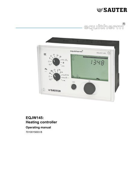
<strong>EQJW145</strong>:<br />
<strong>Heating</strong> <strong>controller</strong><br />
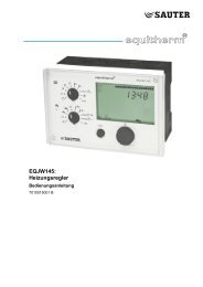
Operating manual<br />
7010015003 B
7010015003 B<br />
Printed in Switzerland<br />
Subject to changes<br />
© Fr. Sauter AG<br />
Im Surinam 55<br />
CH - 4016 Basel<br />
www.<strong>sauter</strong>-<strong>controls</strong>.<strong>com</strong><br />
2 7010015003 B<br />
© Fr. Sauter AG
<strong>EQJW145</strong>:<br />
<strong>Heating</strong> <strong>controller</strong><br />
Table of contents<br />
Table of contents<br />
Table of contents ........................................................................................................ 3<br />
Symbols used in this manual .................................................................................... 7<br />
1 General information ............................................................................................ 9<br />
1.1 Introduction................................................................................................ 9<br />
1.2 Safety information ..................................................................................... 9<br />
2 Description of the operating <strong>controls</strong> ............................................................. 11<br />
2.1 Front view of the EQJW 145 ................................................................... 11<br />
2.2 Top Rotary switches (heating) ................................................................ 12<br />
2.3 Bottom rotary switch (hot water/pilot timer) ............................................. 12<br />
2.4 Input Button ............................................................................................. 13<br />
2.5 ESC key .................................................................................................. 13<br />
2.6 Display ..................................................................................................... 13<br />
3 Commissioning .................................................................................................. 15<br />
3.1 Operating the device for the first time ..................................................... 15<br />
3.1.1 Setting the time ....................................................................................... 15<br />
3.1.2 Setting the date ....................................................................................... 16<br />
3.2 Commissioning level ............................................................................... 16<br />
3.2.1 List of SERVice parameters .................................................................... 17<br />
3.2.2 Access to <strong>com</strong>missioning level ............................................................... 18<br />
3.2.3 View SERVice parameters ...................................................................... 18<br />
3.2.4 Change SERVice parameters ................................................................. 18<br />
3.3 SERVice level ......................................................................................... 19<br />
3.3.1 Access to SERVice level ......................................................................... 19<br />
3.3.2 View SERVice parameters ...................................................................... 20<br />
3.3.3 Change SERVice parameters ................................................................. 20<br />
3.3.4 List of SERVice parameters .................................................................... 21<br />
3.3.5 Explanations for individual SERVice parameters.................................... 25<br />
3.4 Communication level ............................................................................... 38<br />
3.4.1 Access to <strong>com</strong>munication level ............................................................... 39<br />
3.4.2 Viewing the <strong>com</strong>munication parameters ................................................. 39<br />
3.4.3 Changing <strong>com</strong>munication parameters .................................................... 39<br />
3.4.4 List of <strong>com</strong>munication parameters .......................................................... 40<br />
3.4.5 Explanations of individual <strong>com</strong>munication parameters ........................... 42<br />
4 Operation ............................................................................................................ 46<br />
4.1 Operating modes ..................................................................................... 46<br />
4.1.1 Displays when automatic mode is set ..................................................... 47<br />
7010015003 B 3<br />
© Fr. Sauter AG
<strong>EQJW145</strong>:<br />
<strong>Heating</strong> <strong>controller</strong><br />
Table of contents<br />
4.1.2 Displays when back-up mode, reduced mode and normal mode are set49<br />
4.2 Entering the setpoint temperature in normal mode ................................. 50<br />
4.3 Enter setpoint temperature in reduced mode.......................................... 51<br />
4.4 Weekly switching programme for heating ............................................... 51<br />
4.4.1 Calling up the weekly switching programme ........................................... 52<br />
4.4.2 View switching <strong>com</strong>mands ...................................................................... 52<br />
4.4.3 Enter a switching <strong>com</strong>mand .................................................................... 53<br />
4.4.4 Changing and deleting a switching <strong>com</strong>mand ........................................ 53<br />
4.5 Calendar switching programme .............................................................. 54<br />
4.5.1 Calling up the calendar switching programme ........................................ 54<br />
4.5.2 View switching <strong>com</strong>mands ...................................................................... 54<br />
4.5.3 Enter a switching <strong>com</strong>mand .................................................................... 55<br />
4.5.4 Changing and deleting a switching <strong>com</strong>mand ........................................ 55<br />
4.6 Temporary temperature change for the heating circuit ........................... 56<br />
4.7 Entering DHW temperatures ................................................................... 57<br />
4.7.1 Notes on the boosted DHW temperature ................................................ 58<br />
4.8 Weekly switching programme for domestic hot water ............................ 58<br />
4.8.1 Calling up the weekly switching programme ........................................... 59<br />
4.8.2 View switching <strong>com</strong>mands ...................................................................... 59<br />
4.8.3 Enter a switching <strong>com</strong>mand .................................................................... 60<br />
4.8.4 Changing and deleting a switching <strong>com</strong>mand ........................................ 60<br />
4.9 Weekly switching programme for pilot timer/circulating pump ................ 61<br />
4.10 Calling up the weekly switching programme ........................................... 62<br />
4.10.1 View switching <strong>com</strong>mand ........................................................................ 62<br />
4.10.2 Enter switching <strong>com</strong>mand ....................................................................... 62<br />
4.10.3 Change/delete switching <strong>com</strong>mand ........................................................ 63<br />
4.11 Once-only tank charge ............................................................................ 63<br />
5 Manual mode ...................................................................................................... 64<br />
5.1 Access to manual mode (heating) .......................................................... 64<br />
5.2 Access to manual mode (domestic hot water, configurable output and<br />
second final control element) .................................................................. 64<br />
5.3 Set valve position .................................................................................... 64<br />
5.4 Set status of other outputs (pumps, configurable output) for manual<br />
mode ....................................................................................................... 65<br />
5.5 Exit manual mode ................................................................................... 65<br />
5.6 Check measured values in manual mode ............................................... 65<br />
6 Communication functions ................................................................................ 66<br />
6.1 Bus wiring ................................................................................................ 66<br />
6.2 Device bus............................................................................................... 66<br />
4 7010015003 B<br />
© Fr. Sauter AG
<strong>EQJW145</strong>:<br />
<strong>Heating</strong> <strong>controller</strong><br />
Table of contents<br />
6.2.1 Assigning addresses ............................................................................... 66<br />
6.2.2 Room operating unit EDB 100 ................................................................ 67<br />
6.2.3 Sending and receiving outdoor temperatures ......................................... 67<br />
6.2.4 Requesting and processing a heat requirement ..................................... 67<br />
6.2.5 Requesting and processing a return temperature .................................. 67<br />
6.2.6 Synchronising the time ............................................................................ 67<br />
6.3 Modbus <strong>com</strong>munication .......................................................................... 68<br />
6.3.1 Modbus data points (holding register) ..................................................... 69<br />
6.3.2 Modbus data points (coils) ...................................................................... 75<br />
6.4 Modem operation .................................................................................... 76<br />
6.4.1 Connection with the modem .................................................................... 76<br />
6.4.2 Modbus operation via modem ................................................................. 76<br />
6.4.3 Sending SMS if there is a fault on the installation .................................. 77<br />
6.4.4 Displays for modem operation ................................................................ 77<br />
6.5 Setting parameters using the PC ............................................................ 78<br />
7 Faults .................................................................................................................. 80<br />
7.1 Displaying faults ...................................................................................... 80<br />
7.1.1 Error list ................................................................................................... 80<br />
7.1.2 Device status ........................................................................................... 80<br />
7.2 Logbook................................................................................................... 81<br />
7.3 Reset functions ....................................................................................... 82<br />
7.4 Actions to deal with faulty temperature value measurements ................ 82<br />
8 Using the <strong>controller</strong> ........................................................................................... 84<br />
8.1 General information ................................................................................. 84<br />
8.2 Examples of use ...................................................................................... 84<br />
8.2.1 Control model 1 ....................................................................................... 85<br />
8.2.2 Control model 2 ....................................................................................... 88<br />
8.2.3 Control model 3 ....................................................................................... 89<br />
9 Economy tips ..................................................................................................... 90<br />
10 Resistance values for the Ni1000 sensors ..................................................... 92<br />
11 Accessories ....................................................................................................... 94<br />
12 Wiring diagram .................................................................................................. 94<br />
13 Dimension drawing ........................................................................................... 94<br />
14 Technical data .................................................................................................... 96<br />
14.1 Overview of technical data ...................................................................... 96<br />
14.2 Overview of main functions ..................................................................... 98<br />
15 Overview of <strong>controller</strong> settings ...................................................................... 102<br />
15.1 List of SERVice parameters .................................................................. 102<br />
7010015003 B 5<br />
© Fr. Sauter AG
<strong>EQJW145</strong>:<br />
<strong>Heating</strong> <strong>controller</strong><br />
Table of contents<br />
15.2 List of <strong>com</strong>munication parameters ........................................................ 103<br />
15.3 Weekly switching programme: heating ................................................. 104<br />
15.4 Calendar switching programme: heating .............................................. 104<br />
15.5 Weekly switching programme: domestic hot water ............................... 105<br />
15.6 Weekly switching programme: pilot timer/circulating pump .................. 105<br />
Table of Figures ...................................................................................................... 106<br />
List of tables ............................................................................................................ 107<br />
Abbreviations .......................................................................................................... 108<br />
Index ........................................................................................................................ 109<br />
6 7010015003 B<br />
© Fr. Sauter AG
<strong>EQJW145</strong>:<br />
<strong>Heating</strong> <strong>controller</strong><br />
Symbols used in this manual<br />
Symbols used in this manual<br />
Information<br />
Information concerning the use of the product.<br />
Warnings<br />
Factory setting of the EQJW 145 (e.g. manufacturer's specified control<br />
values, switching times, etc.)<br />
The operating instructions explain the various functions of the device, step by<br />
step, using the following symbols:<br />
'PROG' is shown on the display, flashing<br />
'09:00' is shown on the display, not flashing<br />
〈 .... 〉<br />
Press key ...<br />
7010015003 B 7<br />
© Fr. Sauter AG
<strong>EQJW145</strong>:<br />
<strong>Heating</strong> <strong>controller</strong><br />
General information<br />
8 7010015003 B<br />
© Fr. Sauter AG
<strong>EQJW145</strong>:<br />
<strong>Heating</strong> <strong>controller</strong><br />
Symbols used in this manual<br />
1 General information<br />
1.1 Introduction<br />
1.2 Safety information<br />
Congratulations! You have chosen a Sauter heating <strong>controller</strong>. The<br />
equitherm® EQJW 145 is a quality product from one of the leading<br />
manufacturers of control technology products for the heating, ventilation and<br />
air conditioning industry.<br />
The EQJW 145 is a <strong>com</strong>pact, weather-<strong>com</strong>pensated heating <strong>controller</strong> used<br />
to regulate flow temperatures and domestic hot water preparation. In<br />
automatic mode, the EQJW 145 reduces the room temperature during the<br />
night (reduced mode) by means of switching <strong>com</strong>mands from the weekly time<br />
switch (weekly switching programme), and during the day it switches to the<br />
normal temperature. Domestic hot water preparation is switched on or off via<br />
another switching programme. There is a choice of two adjustable<br />
temperatures for domestic hot water. The EQJW 145 is suitable for buildings<br />
of all types. A fixed basic programme (factory setting) ensures that<br />
<strong>com</strong>missioning is simple. Any adaptations to the heating system which might<br />
be needed are implemented using SERVice parameters. Automatic<br />
summertime/wintertime change-over eliminates the need for residents to<br />
adjust the time twice a year. The equitherm® EQJW 145 incorporates a<br />
variety of protective functions such as the anti-frost function and the pump<br />
anti-jamming facility. Additional functions such as automatic switch-off are<br />
also implemented. For every installation, these features ensure optimal<br />
<strong>com</strong>fort with the minimum use of energy.<br />
Analogue or digital room operating units can be connected to the EQJW 145,<br />
enabling convenient remote control of the <strong>controller</strong> from the living room.<br />
A programmable output is provided for additional tasks. For example, it may<br />
be used as a pilot timer output, as a signal for a collective fault alarm, and to<br />
activate a circulating pump for domestic hot water. The <strong>com</strong>munication<br />
interface makes it possible to network several <strong>controller</strong>s, to connect to a<br />
control station and to send alarms to a mobile telephone via SMS.<br />
Special care is required in order to prevent injuries, damage by fire or<br />
damage to equipment. After the device has been installed by a specialist in<br />
accordance with the Installation Instructions enclosed with it (MV506103),<br />
please read these instructions on operating it. Local regulations must be<br />
followed during installation. The <strong>controller</strong> is not a safety-relevant <strong>com</strong>ponent.<br />
The anti-frost, overheating protection and flow temperature limitation<br />
functions do not replace the relevant safety equipment.<br />
7010015003 B 9<br />
© Fr. Sauter AG
<strong>EQJW145</strong>:<br />
<strong>Heating</strong> <strong>controller</strong><br />
General information<br />
10 7010015003 B<br />
© Fr. Sauter AG
<strong>EQJW145</strong>:<br />
<strong>Heating</strong> <strong>controller</strong><br />
Symbols used in this manual<br />
2 Description of the operating <strong>controls</strong><br />
2.1 Front view of the EQJW 145<br />
2<br />
°C<br />
h<br />
sec<br />
1<br />
1<br />
4<br />
3<br />
Fig. 1: EQJW 145 - Front view<br />
1<br />
2<br />
3<br />
4<br />
Rotary switch<br />
Display<br />
ESC button<br />
Input button<br />
The device has a rotary switch with 10 positions, an input button and a<br />
button.<br />
7010015003 B 11<br />
© Fr. Sauter AG
<strong>EQJW145</strong>:<br />
<strong>Heating</strong> <strong>controller</strong><br />
Description of the operating <strong>controls</strong><br />
2.2 Top Rotary switches (heating)<br />
The switch positions have these meanings:<br />
Operating modes:<br />
Automatic mode according<br />
to switching programme<br />
Regulator is<br />
continuously in<br />
1<br />
normal mode<br />
Regulator is<br />
continuously in<br />
reduced mode<br />
Regulator is<br />
continuously in<br />
2<br />
back-up mode<br />
Access to manual mode<br />
for heating<br />
Inputs:<br />
Setpoint adjustment<br />
Normal mode<br />
Setpoint adjustment<br />
Reduced mode<br />
Enter<br />
weekly and<br />
yearly programme for<br />
heating<br />
Limited (unlimited)<br />
temperature change<br />
Access to SERVice and<br />
<strong>com</strong>munication level<br />
Fig. 2: EQJW 145 - Top Rotary Switches<br />
1<br />
2<br />
Normal mode corresponds to nominal mode as per EN 12098-1.<br />
Back-up mode means that the heating is switched off and the anti-frost function is active.<br />
2.3 Bottom rotary switch (hot water/pilot timer)<br />
Operating modes:<br />
Automatic mode for domestic hot<br />
water according to switching<br />
programme<br />
Continuous heating to<br />
increased domestic hot<br />
water temperature<br />
Inputs:<br />
Setpoint for increased<br />
domestic hot water temperature<br />
Continuous heating<br />
to normal domestic hot<br />
water temperature<br />
Domestic hot water<br />
heating switched off<br />
Access to manual mode<br />
Fig. 3: EQJW 145 - Bottom Rotary Switches<br />
If the rotary switches are used to select a prohibited <strong>com</strong>bination of positions,<br />
e.g. simultaneous entry of setpoints for heating and domestic hot water<br />
preparation, the <strong>controller</strong> will show this symbol:<br />
In this case, one of the switches should be set to the symbol or to another<br />
mode.<br />
12 7010015003 B<br />
© Fr. Sauter AG
<strong>EQJW145</strong>:<br />
<strong>Heating</strong> <strong>controller</strong><br />
Symbols used in this manual<br />
2.4 Input Button<br />
You can use the input Button to scroll through menus, and<br />
to select or change values. Unless explicitly described<br />
otherwise, you can scroll through or change<br />
menus/values in a ring structure. There is no 'limit stop'<br />
for adjusting values or scrolling.<br />
The input Button has a key function, i.e. you can press it.<br />
This is used to select the parameter just shown for<br />
changing, or to confirm a flashing value, or to access a<br />
lower menu level.<br />
2.5 ESC key<br />
Press the ESC key to cancel operations, or to return from<br />
a lower menu item to the next level up.<br />
2.6 Display<br />
The device has an LC display (see 2.1), which can show various items of<br />
information at the same time. The next illustration shows what the symbols<br />
mean:<br />
0 1 2 3 4 5 6 7 8..........21 22 23 24<br />
Times for normal mode on the current day<br />
Time, date, setpoints, actual values, etc.<br />
Automatic mode according to the weekly and calendar switching<br />
programme. flashing: temperature change for limited (unlimited) period<br />
<strong>Heating</strong> circuit is in normal mode flashing. Optimisation takes place on<br />
changing to normal mode.<br />
<strong>Heating</strong> circuit is in reduced mode flashing. Optimisation takes place on<br />
changing to reduced or off mode.<br />
<strong>Heating</strong> circuit is in back-up mode. flashing: anti-frost function is active<br />
At least one sensor is faulty (or not connected)<br />
<strong>Heating</strong> medium pump is switched on<br />
Final control element 1 is opened ( ) or closed ( )<br />
Final control element 2 is opened ( ) or closed ( )<br />
Display of setpoint temperature. flashing: display of actual temperature<br />
Display of flow temperature<br />
7010015003 B 13<br />
© Fr. Sauter AG
<strong>EQJW145</strong>:<br />
<strong>Heating</strong> <strong>controller</strong><br />
Description of the operating <strong>controls</strong><br />
Display of outdoor temperature<br />
Display of room temperature<br />
Display of return temperature<br />
Display of tank temperature<br />
Controller is in summer mode<br />
Calendar switching programme mode is currently active<br />
Domestic hot water. flashing: with increased temperature<br />
Charge pump switched on<br />
Status of the configurable output: relay closed<br />
An error has occurred (see 7)<br />
Floor drying function (heating function) is active<br />
14 7010015003 B<br />
© Fr. Sauter AG
<strong>EQJW145</strong>:<br />
<strong>Heating</strong> <strong>controller</strong><br />
Symbols used in this manual<br />
3 Commissioning<br />
3.1 Operating the device for the first time<br />
3.1.1 Setting the time<br />
When you operate the equitherm® EQJW 145 for the first time, you must set<br />
the date and time. Essentially, once this is done, the <strong>controller</strong> is ready for<br />
use. However, depending on the application, it may be necessary to change<br />
further settings after this.<br />
To enable you to set the time, you must first move the bottom rotary switch<br />
into one of the following positions (see 4.1):<br />
Off mode<br />
Continuous heating to normal DHW temperature<br />
Continuous heating to increased DHW temperature<br />
Automatic mode<br />
Procedure<br />
1. Set the top rotary switch to automatic mode.<br />
• The time is shown.<br />
2. Press the input button.<br />
• the time flashes ...<br />
3. Turn the input button.<br />
• The time is set.<br />
4. Press the input button again.<br />
• The new time is confirmed.<br />
If several devices are connected to each other<br />
via a device bus (see 3.4.4) and you set the clock on one device, the time<br />
and date are also set on all the other devices.<br />
7010015003 B 15<br />
© Fr. Sauter AG
<strong>EQJW145</strong>:<br />
<strong>Heating</strong> <strong>controller</strong><br />
Commissioning<br />
3.1.2 Setting the date<br />
To enable you to set the date, you must first move the bottom rotary switch<br />
into one of the following positions (see 4.1):<br />
Off mode<br />
Continuous heating to normal DHW temperature<br />
Continuous heating to increased DHW temperature<br />
Automatic mode<br />
Procedure<br />
1. Set the top rotary switch to automatic mode.<br />
• The time is shown.<br />
2. Turn the input button until the date is displayed<br />
(day/month and year are shown alternately).<br />
3. Press the input button.<br />
• The number of the year flashes...<br />
4. Turn the input button.<br />
• The year is changed.<br />
5. Press the input button.<br />
• The year is confirmed and the day/month<br />
is shown.<br />
6. Turn the input button.<br />
• The date is changed.<br />
7. Press the input button,<br />
• The new date is confirmed.<br />
3.2 Commissioning level<br />
In <strong>com</strong>missioning level, a specialist can perform the basic settings on the<br />
GZP which are important for <strong>com</strong>missioning. Direct access to specified<br />
service parameters is enabled.<br />
Incorrect parameterisation (setting) of the heating <strong>controller</strong><br />
CAUTION!<br />
It can cause major faults or damage to the installation.<br />
The <strong>com</strong>missioning level must only be enabled by a specialist.<br />
Some of the parameters cannot be changed. They can only be viewed<br />
(version number, status information).<br />
16 7010015003 B<br />
© Fr. Sauter AG
<strong>EQJW145</strong>:<br />
<strong>Heating</strong> <strong>controller</strong><br />
Symbols used in this manual<br />
3.2.1 List of SERVice parameters<br />
The following SERVice parameters can be reached on <strong>com</strong>missioning level.<br />
Parameter<br />
Description Range Step value<br />
SP01<br />
Software version Y.XX (read only)<br />
SP06 1 Control model<br />
• 1 = one control valve on the primary side<br />
• 2 = one control valve on the secondary side<br />
• 3 = two control valves on the primary side<br />
0...3 1<br />
SP15 40 Proportional band, PI <strong>controller</strong> in K 2...100 1<br />
SP16 40 MOD3: Proportional band, PI <strong>controller</strong> in K (2nd control circuit) 2...100 1<br />
SP19 120 Runtime for final control element in sec 30...960 15<br />
SP20 180 Runtime for second final control element in sec<br />
• MOD1, 2: for diverter valve (SP34 = 3 or 4)<br />
• MOD3: for second control valve<br />
30...960 15<br />
SP21 5 Minimum limitation of flow temperature T F (heating circuit) in °C 5…100 1<br />
SP22 75 Maximum limitation of flow temperature T F (heating circuit) in °C 20…150 1<br />
SP34 1 Functions for domestic hot water<br />
• 0 = not enabled.<br />
• 1 = MOD 1, 2: with sep. charge pump using one<br />
DHW sensor Tw1<br />
• 2 = MOD 1, 2: with sep. charge pump using two<br />
DHW sensors Tw1, Tw2<br />
• 3 = MOD 1, 2: with diverter valve using one<br />
DHW sensor Tw1<br />
• 4 = MOD 1, 2: with diverter valve using two<br />
DHW sensors Tw1, Tw2<br />
0…4 1<br />
SP35 60 Maximum setpoint for drinking water temperature in °C 10…70 1<br />
SP36 5 MOD 1, 2: Switching difference for domestic hot water in K 1...30 1<br />
SP37 70 Maximum setpoint for increased DHW temperature/[°C] (anti-legionellae<br />
function)<br />
10…90 1<br />
SP38 10 Setpoint boost for domestic hot water in K 0…30 1<br />
SP41 1.4 Slope of heating characteristic 0.2...5.0 0.1<br />
SP60 0 Floor drying<br />
Tab. 1: SERVice parameter<br />
• 0 = not enabled. 7d = enabled. 8 = malfunction<br />
• 9 = successfully <strong>com</strong>pleted<br />
0.7d.8.9 0.7d. 8.9<br />
7010015003 B 17<br />
© Fr. Sauter AG
<strong>EQJW145</strong>:<br />
<strong>Heating</strong> <strong>controller</strong><br />
Commissioning<br />
An overview of the SERVice parameters and explanations for individual<br />
SERVice parameters is given in these sections: 'List of SERVice parameters'<br />
and 'Explanations for individual SERVice parameters'.<br />
3.2.2 Access to <strong>com</strong>missioning level<br />
1. Set the upper rotary switch to the Service<br />
position.<br />
2. Press the input button, select 'In' (=<br />
<strong>com</strong>missioning).<br />
3. Press the input button.<br />
4. Turn the input button,<br />
show the code.<br />
3.2.3 View SERVice parameters<br />
5. Press the input button.<br />
• The first SERVice parameter is displayed.<br />
1. Turn the input button.<br />
2. Select the SERVice parameter you want.<br />
sec<br />
3. Press the input button.<br />
• The value of the parameter is shown.<br />
4. To leave the value unchanged.<br />
5. Press ESC to exit the display.<br />
3.2.4 Change SERVice parameters<br />
Press the ESC key to cancel the operation. The value is not accepted unless<br />
it has already been confirmed.<br />
18 7010015003 B<br />
© Fr. Sauter AG
<strong>EQJW145</strong>:<br />
<strong>Heating</strong> <strong>controller</strong><br />
Symbols used in this manual<br />
1. Turn the input button.<br />
2. Select the SERVice parameter you want.<br />
sec<br />
sec<br />
3. Press the input button.<br />
• The value of the parameter is shown.<br />
4. Turn the input button.<br />
• The value of the parameter is changed.<br />
5. Press the input button.<br />
• The new value is confirmed.<br />
3.3 SERVice level<br />
In SERVice level, a specialist can adapt the basic setting of the EQJW 145 to<br />
the installation so as to meet specific requirements. For this purpose, also<br />
please note the installation instructions enclosed with the EQJW 145<br />
(MV506103).<br />
CAUTION!<br />
Incorrect parameterisation (setting) of the heating <strong>controller</strong><br />
It can cause major faults on the installation, injuries to people or damage to<br />
the installation.<br />
SERVice mode must only be enabled by a specialist.<br />
3.3.1 Access to SERVice level<br />
Some of the parameters cannot be changed - they can only be viewed<br />
(version number, status information).<br />
1. Set the upper rotary switch to the Service<br />
position.<br />
2. Press the input button.<br />
3. Turn the input button.<br />
4. Show the code.<br />
5. Press the input button.<br />
6. The first SERVice parameter is displayed.<br />
7010015003 B 19<br />
© Fr. Sauter AG
<strong>EQJW145</strong>:<br />
<strong>Heating</strong> <strong>controller</strong><br />
Commissioning<br />
3.3.2 View SERVice parameters<br />
1. Turn the input button.<br />
2. Select the SERVice parameter you want.<br />
sec<br />
3. Press the input button.<br />
• The value of the parameter is shown.<br />
4. To leave the value unchanged, press ESC to<br />
exit the display.<br />
3.3.3 Change SERVice parameters<br />
Press the ESC key to cancel the operation. The value is not accepted unless<br />
it has already been confirmed.<br />
sec<br />
1. Turn the input button.<br />
2. Select the SERVice parameter you want.<br />
3. Press the input button.<br />
• The value of the parameter is shown.<br />
sec<br />
4. Turn the input button.<br />
• The value of the parameter is changed.<br />
5. Press the input button.<br />
• The new value is confirmed.<br />
20 7010015003 B<br />
© Fr. Sauter AG
<strong>EQJW145</strong>:<br />
<strong>Heating</strong> <strong>controller</strong><br />
Symbols used in this manual<br />
3.3.4 List of SERVice parameters<br />
Parameter Description Range Step value<br />
SP01<br />
Software version Y.XX (read only)<br />
SP02 0 Device status (error coding) (read only)<br />
1<br />
SP03 View logbook -<br />
SP04 0 Software reset<br />
SP05 0 Manual mode<br />
SP06 1 Control model<br />
• 0 = no Reset<br />
• 1 = factory setting for SE + CO parameters<br />
• 2 = factory setting for switching <strong>com</strong>mands<br />
• 3 = factory setting for SE- + CO parameters +<br />
switching <strong>com</strong>mands<br />
• 0 = manual mode not enabled<br />
• 1 = manual mode enabled<br />
• 1 = one control valve on the primary side<br />
• 2 = one control valve on the secondary side<br />
• 3 = two control valves on the primary side<br />
SP07 0 Effect of binary / pulse input (terminals 21, 22)<br />
• 0 = HK in back-up mode if contact is closed.<br />
• 1 = HK in reduced mode if contact is closed.<br />
• 2 = HK in nominal mode if contact is closed.<br />
• 3 = Pulse input for quantity metering<br />
• 4 = Seepage limitation<br />
• 5 = Input for fault signal<br />
SP08 0 Room temperature recording<br />
SP09 0 Connect room temperature<br />
• 0 = no room temperature recording<br />
• 1 = connect room sensor<br />
• 2 = connect EGS52/15 or EGT 333 with room sensor<br />
• 3 = connect EGS52/15 or EGT 333 without room<br />
sensor<br />
• 4 = MOD1,2: 2nd flow sensor for DHW (SP49 = 2)<br />
• 0 = not enabled<br />
• 1 = enabled if TRi > TRs<br />
0...3 1<br />
0...1 1<br />
0...3 1<br />
0…5 1<br />
0...4 1<br />
0...3 1<br />
• 2 = enabled if TRi < TRs<br />
• 3 = enabled if TRi TRs<br />
SP10 20 Scanning time for room temperature if connected /[min] 1…100 1<br />
SP11 0 Correction to room temperature TRi in K -6.0...+6.0 0.1<br />
7010015003 B 21<br />
© Fr. Sauter AG
<strong>EQJW145</strong>:<br />
<strong>Heating</strong> <strong>controller</strong><br />
Commissioning<br />
Parameter Description Range Step value<br />
SP12 0 Correction to outdoor temperature TA in K -10.0…+10.0 0.1<br />
SP13 0 Return temperature recording<br />
0…1 1<br />
• 0 = return temperature is not recorded<br />
• 1 = return temperature is recorded<br />
SP14 0 Correction to return temperature TRF (MOD3: TRF of heating circuit) -10.0…+10.0 0.1<br />
SP15 40 Proportional band, PI <strong>controller</strong> in K 2...100 1<br />
SP16 40 MOD3: Proportional band, PI <strong>controller</strong> in K (2nd control circuit) 2...100 1<br />
SP17 240 Reset time, PI <strong>controller</strong> in sec 5...1000 5<br />
SP18 240 MOD3: Reset time, PI <strong>controller</strong> in sec (2nd control circuit) 5...1000 5<br />
SP19 120 Runtime for final control element in sec 30...960 15<br />
SP20 180 Runtime for second final control element in sec<br />
30...960 15<br />
MOD1, 2: for diverter valve (SP34 = 3 or 4)<br />
MOD3: for second control valve<br />
SP21 5 Minimum limitation for flow temperature TF (heating circuit) in °C 5 …100 1<br />
SP22 75 Maximum limitation for flow temperature TF (heating circuit) in °C 20…150 1<br />
SP23 90 Upper limit value for max. limitation of TRF during heating<br />
in °C<br />
5…150 1<br />
SP24 90 Lower limit value for max. limitation of TRF during heating in °C 5…150 1<br />
SP25 0 Outdoor temperature at which the sliding part of the limit function for<br />
TRF begins, in °C<br />
-30...+50 1<br />
SP26 1.0 Slope of limitation function for TRF in [K/K] 0.0…5.0 0.1<br />
SP27 90 Maximum limitation for return temperature TRF during DHW<br />
heating in °C<br />
SP28 1 Level of intervention when limit value of the return temperature is<br />
breached max. TRF in [K/K] (TN fixed at 400s)<br />
5…150 1<br />
0.1…10 0.1<br />
SP29 no Limit value pulse/min for max. flow or power of heating and DHW no 0.1...16.0.<br />
60...16000<br />
SP30 no Limit value pulse/min for max. flow or power of heating only no 0.1...16.0.<br />
60...16000<br />
SP31 no Limit value pulse/min for max. flow or power of DHW only no 0.1...16.0.<br />
60...16000<br />
0.1/1/10<br />
0.1/1/10<br />
0.1/1/10<br />
SP32 0.0 Intervention intensity in K/min if limit value for flow or power is violated 0.0…30.0 0.1<br />
SP33 no Limit value pulse/min for min. flow or power no. 0.1...16.0.<br />
60...16000<br />
0.1/1/10<br />
22 7010015003 B<br />
© Fr. Sauter AG
<strong>EQJW145</strong>:<br />
<strong>Heating</strong> <strong>controller</strong><br />
Symbols used in this manual<br />
Parameter Description Range Step value<br />
SP34 1 Functions for DHW<br />
• 0 = not enabled.<br />
• 1 = MOD 1, 2: with sep. charge pump using one<br />
DHW sensor<br />
• 2 = MOD 1, 2: with sep. charge pump using two<br />
DHW sensors<br />
• 3 = MOD 1, 2: with diverter valve using one DHW<br />
sensor<br />
• 4 = MOD 1, 2: with diverter valve using two DHW<br />
sensors<br />
0…4 1<br />
SP35 60 Maximum setpoint for domestic hot water temp./[°C] 10…70 1<br />
SP36 5 MOD 1, 2: switching difference for DHW in K 1...30 1<br />
SP37 70 Maximum setpoint for increased DHW temperature/[°C] 10…90 1<br />
SP38 10 Setpoint increase for charge of drinking water in K 0…30 1<br />
SP39 -30 Outdoor temperature limit value for operation of domestic hot water<br />
heating in °C<br />
• TA < limit value parallel operation<br />
• TA > limit value domestic hot water with priority<br />
-30…50 1<br />
Note: only valid if value SP34 = 1 or 2<br />
SP40 4 After-run time for charge pump for domestic hot water/[min] 0…20 1<br />
SP41 1.4 Slope of heating characteristic 0.2...5.0 0.1<br />
SP42 10 Setpoint boost for demand request via device bus/ [ K] 0…30 1<br />
SP43 0.0 External heat portion/[K] 0.0...5.0 0.1<br />
SP44 15 <strong>Heating</strong> limit/[°C] 0...39 1<br />
SP45 21 Damping of outside temperature measurement for heating limit in<br />
hours<br />
• SP45 = 0 TA used without damping for heating limit<br />
function<br />
• SP45 > 0 time constant for damping TA for heating<br />
limit function<br />
0…30 1<br />
SP46 -16 Design temperature/[°C] -30...0 1<br />
SP47 2 After-run factor for heating medium pump (after-run time = runtime for<br />
final control element x after-run factor)<br />
SP48 2 Anti-frost function<br />
• 0 = not enabled<br />
• 1 = enabled (TP off when frost)<br />
• 2 = enabled (TP on when frost)<br />
1…10 1<br />
0...2 1<br />
7010015003 B 23<br />
© Fr. Sauter AG
<strong>EQJW145</strong>:<br />
<strong>Heating</strong> <strong>controller</strong><br />
Commissioning<br />
Parameter Description Range Step value<br />
SP49 0 Configurable output<br />
• 0 = no function<br />
• 1 = pilot timer function<br />
• 2 = 2nd tank charge pump (MOD1, 2 only)<br />
• 3 = forced control of heating medium pump at low<br />
speed in reduced and back-up mode<br />
• 4 = collective fault alarm<br />
• 5 = circulating pump<br />
• 6 = heat requirement<br />
SP50 0 Pump anti-jamming facility<br />
• 0 = not enabled. 1 = enabled<br />
0…6 1<br />
0…1 1<br />
SP51 25.10 Summer/winter time changeover 01.01 ...<br />
31.12<br />
SP52 25.03 Winter/summer time changeover<br />
• SP51 = SP52 means no summer/winter time<br />
changeover<br />
SP54 0 Temporary heating mode<br />
• 0 = not active<br />
SP53 0 Optimisation<br />
• 1 = active<br />
• 0 = not enabled. 1 = enabled<br />
01.01 ...<br />
31.12<br />
0…1 1<br />
0…1 1<br />
SP60 0 Floor drying<br />
• 0 = not enabled<br />
• 7d = functional heating<br />
• 25°C = ready-for-laying heating<br />
• 8 = malfunction<br />
• 9 = successfully <strong>com</strong>pleted<br />
0.7d.25°C.8.9 0.7d.25°C.8<br />
.9<br />
SP61 0 Type of sensor<br />
• 0 = Ni1000<br />
• 1 = Pt1000<br />
Tab. 2: SERVice parameter<br />
0…1 0<br />
24 7010015003 B<br />
© Fr. Sauter AG
<strong>EQJW145</strong>:<br />
<strong>Heating</strong> <strong>controller</strong><br />
Symbols used in this manual<br />
3.3.5 Explanations for individual SERVice parameters<br />
SP01<br />
SP02<br />
View software version<br />
The <strong>controller</strong>'s software version number is shown.<br />
View device status<br />
SERVice parameter 2 allows you to read the device status of the EQJW 145.<br />
Value 0 means that the EQJW 145 is operating without faults. The coding for<br />
faults is shown in section7.1.2. Once the fault is rectified, the value for the<br />
SERVice parameter is reset automatically.<br />
Note: this coded error description is primarily used to signal faults via bus,<br />
modem or SMS. Faults can be conveniently read directly from the ERROR<br />
display on the <strong>controller</strong> (see7.1).<br />
SP03<br />
SP04<br />
SP05<br />
SP06<br />
Logbook<br />
This is not a parameter but an indicator for the logbook, in which the date,<br />
time and type of fault is entered for every fault that occurs during operation.<br />
Further information on this function can be found in section 7.2.<br />
Software reset<br />
Switching <strong>com</strong>mands and/or SERVice or <strong>com</strong>munication parameters are<br />
returned to the factory setting. To do this, the value of the SERVice<br />
parameter must be changed and confirmed. After this, the EQJW 145<br />
performs the relevant reset and assigns value 0 to the parameter.<br />
Manual mode<br />
SERVice parameter SP05 is used to disable or enable manual mode. If the<br />
value of the parameter is 0, manual mode is disabled.<br />
Control model<br />
Various control models are stored in the EQJW 145. Use this parameter to<br />
specify the model that the EQJW 145 uses as the basis for control. The<br />
following control models are available for selection.<br />
• MOD1: one control valve on the primary side<br />
(SP06 =1)<br />
• MOD2: one control valve on the secondary side (SP06 = 2)<br />
• MOD3: two control valves on the primary side (SP06 = 3)<br />
With MOD1 and MOD2, it is possible not only to control a heating circuit but<br />
also to prepare DHW. SERVice parameter 33 can be used to configure the<br />
DHW preparation.<br />
With MOD3, the second control valve on the primary side is used for fixedvalue<br />
control (e.g. for DHW preparation). The assignment of T F2 or T RF2 to<br />
the appropriate terminal is done automatically (see wiring diagram). More<br />
information about the control models and the most important applications is<br />
given in the section on 'Information on applications'.<br />
7010015003 B 25<br />
© Fr. Sauter AG
<strong>EQJW145</strong>:<br />
<strong>Heating</strong> <strong>controller</strong><br />
Commissioning<br />
SP07<br />
Effect of binary / pulse input (terminals 21, 22)<br />
If the external switching contact is closed, this SERVice parameter can be set<br />
appropriately (SP07 = 0, 1 or 2) to influence the heating programme, as long<br />
as the <strong>controller</strong> is in automatic mode. If the contact is opened again, the<br />
<strong>controller</strong> will operate according to the weekly / calendar switching<br />
programme again and the following apply:<br />
• 0 = HK in back-up mode if contact is closed<br />
• 1 = HK in reduced mode if contact is closed<br />
• 2 = HK in nominal mode if contact is closed<br />
Alternatively, the input can be used for quantity metering (and therefore for<br />
quantity limitation as well), to limit see page or to forward a fault signal (using<br />
a modem via SMS or via the configurable relay output to another device). For<br />
SP07, the values mean:<br />
• 3 = input used as pulse input for quantity metering<br />
• 4 = input used to limit seepage<br />
The minimum flow can be limited. A signal from the auxiliary contacts of a<br />
control unit can be used to do this. If the contact input is closed, the valve<br />
on the primary side closes and is not opened again until the setpoint for<br />
the flow temperature is 5K higher than the actual value.<br />
• 5 = input is a fault signal input, used to forward fault signals from other<br />
devices<br />
SP08<br />
Room temperature recording<br />
Various types of room temperature sensor can be connected:<br />
• 0 = no room temperature recording<br />
• 1 = connect room sensor<br />
• 2 = connect EGS52/15 or EGT333 with room sensor<br />
• 3 = connect EGS52/15 or EGT333 without room sensor<br />
• 4 = only for MOD1,2 with second tank charge pump (SP49 = 2): the<br />
analogue input (terminal 28) is not used as a room sensor but as a second<br />
flow sensor for DHW preparation (also see the section on 'Application<br />
examples').<br />
Room operating unit EGS52/15 allows you to switch over the <strong>controller</strong>'s<br />
mode remotely. Room operating unit EDB100 can also be connected via the<br />
device bus and used to switch the mode over. The mode on the <strong>EQJW145</strong><br />
can also be changed using a control station via Modbus. In case of<br />
contradictory <strong>com</strong>mands, the following priority applies: direct settings on<br />
<strong>EQJW145</strong> have priority 1. A setting using room operating unit EDB100 via<br />
device bus or a preset via Modbus have priority 2. The setting via the binary<br />
input has priority 3. Settings on room operating unit EGS52/15 have the<br />
lowest priority. If the setpoint for the room temperature is changed via the<br />
setpoint transmitter of the EGS 52/15 or EGT 333 room operating units, it<br />
also changes the actual value for the room temperature at the sensor input of<br />
26 7010015003 B<br />
© Fr. Sauter AG
<strong>EQJW145</strong>:<br />
<strong>Heating</strong> <strong>controller</strong><br />
Symbols used in this manual<br />
the EQJW 145. This, in turn, means that the flow temperature and, therefore,<br />
the heating capacity, for the room are altered accordingly.<br />
SP09<br />
Connect room temperature<br />
A room temperature sensor (resistance sensor or device bus) is required for<br />
this function. The flow temperature setpoint is changed – in divergence from<br />
the setpoint according to the heating characteristic – if the room temperature<br />
in the reference room diverges from the room setpoint. The change in flow<br />
temperature is limited to a maximum of ± 30K.<br />
SP09 = 1 or 2 can be used to allow the room temperature connection to<br />
influence the flow setpoint in one direction only. The meanings are:<br />
• 0 = flow temperature is not changed, i.e. the room temperature connection<br />
is not enabled<br />
• 1 = flow setpoint can only be reduced, i.e. the room temperature<br />
connection is only enabled if TRi > TRs<br />
• 2 = flow setpoint can only be increased, i.e. the room temperature<br />
connection is only enabled if TRi < TRs<br />
• 3 = flow setpoint can be reduced and increased, i.e. the room temperature<br />
connection is enabled if TRi TRs<br />
SP10<br />
Scanning time for room temperature if connected<br />
If the room temperature connection is enabled, this SERVice parameter<br />
determines the period within which a one-off adaptation of the flow setpoint<br />
can occur. In "heavy" buildings with sluggish heating systems, a higher value<br />
is more suitable than it would be for buildings of lightweight construction and<br />
heating that reacts quickly. This time must not be too short, so as to prevent<br />
control fluctuations. The algorithm prevents hunting by changing the flow<br />
setpoint more quickly (at a rate of ±2 K within a scanning period) when the<br />
deviation of the room temperature is diminishing than when it is increasing (at<br />
a rate of ±1 K within a scanning period). If the deviation of the room<br />
temperature is less than 0.25 K, the flow setpoint is not altered. In most<br />
cases, the factory setting (20 minutes) provides satisfactory results for<br />
residential buildings. As a general rule, the factory setting (20 minutes) leads<br />
to satisfactory results in residential buildings.<br />
Open windows or other cooling or heating loads can influence control!<br />
Sudden removal of these influences can lead to the value moving above or<br />
below the room temperature in the opposite direction for short periods!<br />
SP11<br />
SP12<br />
Correction to room temperature<br />
The measured value for the room temperature is calibrated with the help of<br />
this SERVice parameter. The value that was entered is added to the<br />
measured value for the room temperature.<br />
Correction to outdoor temperature<br />
The measured value for the outdoor temperature is calibrated with the help of<br />
this SERVice parameter. The value that was entered is added to the<br />
measured value for the outdoor temperature.<br />
7010015003 B 27<br />
© Fr. Sauter AG
<strong>EQJW145</strong>:<br />
<strong>Heating</strong> <strong>controller</strong><br />
Commissioning<br />
SP13<br />
SP14<br />
SP15<br />
SP16<br />
SP17<br />
SP18<br />
SP19<br />
SP20<br />
SP21, 22<br />
SP23 – SP27<br />
Return temperature recording<br />
If a return temperature sensor is to be used, this parameter must be set to 1.<br />
Correction to return temperature<br />
The measured value for the return temperature is calibrated with the help of<br />
this SERVice parameter. The value that was entered is added to the<br />
measured value for the return temperature. If there are two return sensors<br />
(MOD3), this parameter only affects the TRF of the heating circuit.<br />
Proportional band<br />
SERVice parameter 15 specifies the proportional band (XP) of PI control for<br />
the flow temperature in K.<br />
Proportional band – 2nd control circuit (only MOD3)<br />
SERVice Parameter 16 specifies the proportional band (XP) of PI control for<br />
the second control circuit in K.<br />
Reset time<br />
SERVice parameter 17 specifies the reset time (TN) of PI control for the flow<br />
temperature in seconds.<br />
Reset time – 2nd control circuit (only MOD3)<br />
SERVice parameter 18 specifies the reset time (TN) of PI control for the<br />
second control circuit in seconds.<br />
Runtime for actuator of control valve<br />
Valves with a motorised actuator need a specified time to open or close<br />
<strong>com</strong>pletely. This is known as the valve runtime. This SERVice parameter is<br />
used to set the equitherm® EQJW 145 to the runtime of the valve drive that<br />
is used. Optimal control quality and various protective functions are only<br />
ensured if the valve runtime is set correctly.<br />
Runtime for second actuator<br />
Depending on the control model, a second control valve is used on the<br />
primary side, or a changeover valve is used on the secondary side. SERVice<br />
parameter SP20 is used to set the valve runtime for the second actuator.<br />
Minimum and maximum limits for flow temperature<br />
The setpoint for the flow temperature can be limited. The value of SERVice<br />
parameter SP21 sets the lower limit in this case, and the value of SERVice<br />
parameter 22 sets the upper limit. Parameters SP21 and SP22 specify a<br />
minimum and maximum flow temperature.<br />
Limiting function for the return temperature<br />
A limiting function can be set for the primary-side return temperature of the<br />
converter. If the value falls below the limiting function, the flow temperature is<br />
adjusted (also see SP28). The following illustration shows the limiting<br />
function.<br />
28 7010015003 B<br />
© Fr. Sauter AG
<strong>EQJW145</strong>:<br />
<strong>Heating</strong> <strong>controller</strong><br />
Symbols used in this manual<br />
TRF max.<br />
TL0 (RF)<br />
TL0BW (RF)<br />
TLU (RF)<br />
TA (RF)<br />
TA<br />
B10980<br />
Fig. 4: Limitation function<br />
The following parameters are available to set the limiting function:<br />
SP23<br />
SP24<br />
SP25<br />
SP26<br />
SP27<br />
Upper value of maximum limit for primary return temperature<br />
(T LO(RF) ) for heating.<br />
Lower value of maximum limit for primary return temperature<br />
(T LU(RF) ) for heating.<br />
Outdoor temperature (T A(RF) ) at which the sliding portion of<br />
the limiting function for the primary return temperature starts<br />
during heating.<br />
Slope (S L(RF) ) of the sliding portion of the limiting function for<br />
the primary return temperature for heating.<br />
Maximum limit (T LOBW(RF) ) for the primary return temperature<br />
during DHW heating.<br />
In MOD1 or MOD2, if the heating is in reduced or normal mode and DHW<br />
heating occurs at the same time, the maximum limit value for the primary<br />
return temperature is checked with the outdoor-temperature-dependent value<br />
for the heating circuit and the fixed value for the DHW during this time.<br />
To make the return temperature limitation effective, return temperature<br />
recording must be enabled (see SP13). In summer mode, or if the heating is<br />
in back-up mode, the limitation on the return temperature for the heating is<br />
not enabled.<br />
SP 28<br />
Intervention intensity if return temperature is exceeded<br />
If the limiting function for the return temperature, set by SP23-SP27, is<br />
exceeded, a PI control algorithm intervenes. For every degree above the<br />
limit, the algorithm reduces the setpoint for the flow temperature by the<br />
amount stipulated in SP28. The integral action time T N of the correcting<br />
algorithm is set (fixed) at 400 s.<br />
SP29 - SP31<br />
7010015003 B 29<br />
© Fr. Sauter AG
<strong>EQJW145</strong>:<br />
<strong>Heating</strong> <strong>controller</strong><br />
Commissioning<br />
Maximum limit values for quantity metering<br />
SP29, SP30 and SP31 specify maximum limit values for quantity metering<br />
(i.e. usually for the flow or heat quantity/power). SP29 defines the maximum<br />
limit value for heating and DHW, SP30 only defines this value for the heating<br />
and SP31 only defines it for DHW. The value is always entered in units of<br />
'pulses per minute'. See the following examples of converting the limit value<br />
for the flow volume or power to the 'Pulses per minute' variable.<br />
Example 1:<br />
The flow volume should be limited to 1.6 m³ / hour.<br />
The flow sensor transmits a signal of 50 pulses / litre.<br />
The following conversion: 1.6 m³ / hour = 1,600 litres / hour and 1600 litres /<br />
hour = 26.67 litres / minute, and the flow sensor variable of 50 pulses / litre,<br />
give a limit value that must be entered on the <strong>EQJW145</strong> (SP29, SP30 or<br />
SP31) of 26.67 litres / min x 50 pulses / litre = 1333 pulses / min.<br />
Example 2:<br />
The power in heating mode should be limited to 35kW. With simultaneous<br />
heating operation and DHW heating, 50 kW should be allowed. A heat<br />
quantity meter is available which outputs 1200 pulses / kWh.<br />
The following conversion: 35 kW = 35 kWh / h and the given variable for the<br />
heat quantity meter provide 35 kWh / h x 1200 pulses / kWh = 42,000 pulses<br />
/ h. This gives a value that must be entered on the <strong>EQJW145</strong> of 42,000<br />
pulses / h = 42,000 : 60 pulses / min = 700 pulses / min. The second limit<br />
value is 50 kW. The same conversion: (50 kWh / h x 1200 pulses / kWh x 1h<br />
/ 60 min = 1000 pulses / min) gives a value of 1000 pulses / min that must be<br />
entered in the <strong>EQJW145</strong>. In the <strong>EQJW145</strong>, a value of 1000 should be<br />
assigned to SP29 and a value of 700 to SP30.<br />
The <strong>EQJW145</strong> switches automatically between the following two measuring<br />
methods.<br />
• measurement of time interval (time interval measurement) between two<br />
pulses and calculation of the 'pulses per minute' variable<br />
• measurement of the number of pulses per minute (pulse measurement) .<br />
If the three set limit values (SP29 to SP31) are in the range 0.1 - 16.0, the<br />
<strong>EQJW145</strong> automatically switches over to time interval measurement. If a<br />
value between 60 and 16.000 is entered for one of SERVice parameters<br />
SP29 to SP31, the <strong>controller</strong> switches over automatically to pulse<br />
measurement.<br />
A limit value of between 16 and 60 pulses / minute cannot be entered<br />
because the measurement accuracy required for control is no longer<br />
available in this range. If a value in the range from 60 to 16,000 has been<br />
entered for one of the limit values (SP29, SP30 or SP31), the other two<br />
limit values must be in the range from 60 to 16,000 or must be disabled<br />
(value of SERVice parameter = 'no'). Otherwise, there may be faulty<br />
30 7010015003 B<br />
© Fr. Sauter AG
<strong>EQJW145</strong>:<br />
<strong>Heating</strong> <strong>controller</strong><br />
Symbols used in this manual<br />
monitoring of the limit value leading to faulty control behaviour. During DHW<br />
heating at increased DHW temperature, the limiting function is not enabled<br />
so that protection against legionella can be enabled if required.<br />
SP32<br />
SP33<br />
Intervention intensity in case of violation of maximum limit value for quantity<br />
measurement<br />
The flow temperature is reduced each minute by the value that was entered<br />
for SP32 if the limit for quantity metering is violated. The flow temperature is<br />
adapted 'continuously' (i.e. about once a second) to its value in this case. If<br />
the value falls below the limit value for quantity measurement again, the flow<br />
temperature is increased again at 1/5 of the set intervention intensity.<br />
Limit value for minimum flow or power<br />
This function is used to limit see page. It prevents a constant low flow if the<br />
energy requirement is low. In this case, the mixer is closed and only opened<br />
again if a control divergence of over 5 K occurs. The value is entered in<br />
pulses / min.<br />
To convert the limit value for flow or power into a value in units of pulses /<br />
min, see the examples given with the explanations for SP29 to SP32.<br />
SP34<br />
Functions for DHW<br />
The plant structure for control model MOD1, 2 (see SP06, control models)<br />
can be extended by adding DHW preparation. SP34 must be set as per the<br />
existing DHW preparation.<br />
separate charge pump<br />
diverter valve<br />
one DHW sensor SP34 = 1, SP34 = 3<br />
two DHW sensors SP34 = 2 SP34 = 4<br />
Tab. 3: DHW preparation<br />
If the SERVice parameter has value 0, the DHW functions are not enabled<br />
(except with MOD3).<br />
SP35<br />
SP36<br />
Maximum permitted DHW temperature<br />
This SERVice parameter is used to impose an upper limit on the temperature<br />
for domestic hot water, which can be set with the lower rotary switch. If the<br />
rotary button used to set the values is turned further to the right (increase<br />
values) although the upper limit value has already been reached, the display<br />
will automatically show the lowest value, which is increased again.<br />
Switching difference DHW<br />
The tank charge is not started as soon as the target temperature for the<br />
DHW is undercut, but when the switching difference that was set here (e.g.<br />
5K) has been undercut. This prevents a fresh charge having to be carried out<br />
shortly after a charge has finished.<br />
SP37<br />
7010015003 B 31<br />
© Fr. Sauter AG
<strong>EQJW145</strong>:<br />
<strong>Heating</strong> <strong>controller</strong><br />
Commissioning<br />
Maximum permitted increased DHW temperature<br />
This SERVice parameter is used to set an upper limit for the increased<br />
temperature for domestic hot water, which can be set with the lower rotary<br />
switch. If the rotary button used to set the values is turned further to the right<br />
(increase values) although the upper limit value has already been reached,<br />
the display will automatically show the lowest value, which is increased<br />
again.<br />
SP38<br />
SP39<br />
SP40<br />
Setpoint boost for charge of drinking water<br />
The heating temperature must be higher than the desired tank temperature<br />
for the domestic hot water, otherwise minor temperature losses during<br />
heating would mean that the tank heating never ends. This SERVice<br />
parameter specifies the amount by which the heating temperature should<br />
exceed the desired tank temperature + switching difference.<br />
Outdoor temperature limit value for operation of domestic hot water heating<br />
Depending on the outdoor temperature, the EQJW 145 determines whether<br />
heating of the domestic hot water tank is carried out as a priority - i.e. the<br />
heating medium pump is switched off during heating - or in parallel. If the<br />
measured outdoor temperature is below the limit value set with the help of<br />
SP39, parallel operation of heating and tank heating is implemented. If the<br />
outdoor temperature is higher than this limit value, domestic hot water<br />
heating is implemented with priority. If value –30°C is set for SP39, parallel<br />
operation is generally disabled.<br />
After-run time for charge pump for domestic hot water<br />
After the desired tank temperature has been reached, the charge pump is not<br />
switched off immediately. Instead, it continues running for a period that can<br />
be set here (in minutes). In this way, for example, a flow temperature that is<br />
too high for the heating circuit can be reduced. The after-run time for the<br />
charge pump is interrupted prematurely if TFi ≤ TWi + 2K or TFi ≤ TFs for the<br />
heating circuit.<br />
32 7010015003 B<br />
© Fr. Sauter AG
<strong>EQJW145</strong>:<br />
<strong>Heating</strong> <strong>controller</strong><br />
Symbols used in this manual<br />
SP41<br />
Slope of heating characteristic<br />
The flow temperature is controlled according to the outdoor temperature. The<br />
heating characteristic in the <strong>controller</strong> determines the setpoint for the flow<br />
temperature in relation to a given outdoor temperature.<br />
2,5 3,0 3,5 4,0<br />
2,0<br />
100<br />
[°C]<br />
1,8<br />
1,6<br />
SP41: SP17: Slope of of<br />
90<br />
80<br />
1,4<br />
heating characteristic<br />
70<br />
1,2<br />
1,0<br />
0,8<br />
60<br />
50<br />
0,6<br />
40<br />
0,4<br />
30<br />
-20 -15 -10 -5 0 5 10 15<br />
[°C] Outdoor temperature<br />
T I<br />
[°C]<br />
-10 -5 5<br />
Fig. 5: Guideline for the slope of the heating characteristic:<br />
1,4 for hot water radiator heaters ( )<br />
1,0 for low-temperature heaters<br />
0,6 for floor heaters<br />
SP42<br />
SP43<br />
SP44<br />
Setpoint boost for a demand requirement via the device bus<br />
When heat from another device is requested via the device bus, SP42 can be<br />
used to make the <strong>EQJW145</strong> control to a setpoint that is higher by the amount<br />
entered for SP42 (0K to 30K) than the amount actually requested by the<br />
other device. This can improve control behaviour for cascaded <strong>controller</strong>s.<br />
Extraneous heat portion<br />
Continual incidence of extraneous heat (e.g. due to the presence of people,<br />
loss of heat from machines) can be taken into account by the EQJW 145 and<br />
<strong>com</strong>pensated by a horizontal shift of the heating characteristic towards a<br />
lower outdoor temperature.<br />
<strong>Heating</strong> limit<br />
If the outdoor temperature is higher than the heating limit, heating operation<br />
is stopped, i.e. the EQJW 145 goes into summer mode. As soon as the value<br />
falls back below the heating limit, heating operation is resumed and summer<br />
mode is ended again. To avoid frequent status changes, a hysteresis of 1K is<br />
taken into account in both cases.<br />
The outdoor temperature required for this function can either be measured<br />
with an outdoor temperature sensor or can be received via a connected<br />
device bus. For this function, there is a choice between the current measured<br />
outdoor temperature or the averaged outdoor temperature over the last 21<br />
hours (see SP45 on this point).<br />
7010015003 B 33<br />
© Fr. Sauter AG
<strong>EQJW145</strong>:<br />
<strong>Heating</strong> <strong>controller</strong><br />
Commissioning<br />
SP45<br />
SP46<br />
SP47<br />
SP48<br />
SP49<br />
Damping for outside temperature measurement for heating limit<br />
The EQJW 145 can be used either for the heating limit (see SP44), for the<br />
currently measured outside temperature or for an attenuated outside<br />
temperature. If the outside temperature, averaged over the last 21 hours, is<br />
used, the influence of brief fluctuations – and, therefore, the frequent<br />
switching (on and off) of the heating system – can be avoided. If SP45 equals<br />
0, the current outside temperature is used. Otherwise, the value of SP45<br />
equals the time constant of the damping in hours. The factory setting for<br />
SP45 is 21 hours.<br />
Design temperature<br />
If the current outdoor temperature is lower than the design temperature, the<br />
EQJW 145 heating <strong>controller</strong> no longer switches to reduced mode but<br />
remains in normal mode instead.<br />
After-run factor for heating medium pump<br />
When heating mode ends, the heating medium pump is not switched off<br />
immediately, but only after a delay that can be preset with SP47. For a valve<br />
running time (SP19) of 120s, an after-run factor of 2 therefore means an<br />
after-run time of 240 s = 4 minutes for the heating pump.<br />
Anti-frost<br />
The anti-frost function be<strong>com</strong>es active if the outdoor temperature falls below<br />
the anti-frost limit (= +3°C). If the outdoor temperature rises above 4°C again,<br />
the function is terminated. The flashing symbol indicates that the anti-frost<br />
function is active. There is a forced switch-on of the heating medium pump.<br />
The setpoint for the flow temperature of the heating circuit is set at +10°C<br />
unless it is already higher. The DHW temperature is monitored for a minimum<br />
temperature of +5°C. If it falls below this value, the domestic hot water is<br />
heated to +10°C. In addition, regardless of the outdoor temperature, the flow<br />
temperature is monitored for a limit value of 5°C. If SP48=0, the function can<br />
be disabled and the <strong>controller</strong> will no longer offer an anti-frost function in this<br />
case!<br />
SP48 =1 enables the frost-protection function; the circulation pump (see also<br />
SP49) is switched off in the event of frost.<br />
SP48 =2 enables the frost-protection function; the circulation pump (see also<br />
SP49) remains switched on in the event of frost.<br />
Function of the configurable output<br />
One of the output relays of the EQJW 145 can be used for various tasks.<br />
SP49 specifies the use of the output. Depending on the value of SP49, the<br />
output has the following functions:<br />
• 0 = output has no function<br />
• 1 = Pilot timer function<br />
The output is controlled only in relation to the time programme that was<br />
entered for the relay. This enables switching of any desired consumer<br />
according to the time programme, independently of the heating. The relay<br />
34 7010015003 B<br />
© Fr. Sauter AG
<strong>EQJW145</strong>:<br />
<strong>Heating</strong> <strong>controller</strong><br />
Symbols used in this manual<br />
is opened if the normal operating mode has been set in the time<br />
programme. For any other operating mode, the relay is closed.<br />
• 2 = 2nd tank charge pump (only MOD1, 2)<br />
The 2nd tank charge pump is switched on if the actual value for the flow<br />
temperature is greater than the setpoint temperature for the DHW for start<br />
of heating + setpoint boost DHW (see SP38).<br />
The 2nd tank charge pump always runs on for the full after-run time (see<br />
SP40), i.e. the break off criteria for the DHW charge pump do not apply<br />
(see SP40).<br />
• 3 = Forced control of the heating medium pump to low speed<br />
The relay contact is closed as soon as the <strong>controller</strong> is in reduced or off<br />
mode. This signal can be connected up to a pump speed <strong>controller</strong> so as<br />
to reduce the pump speed in reduced or off mode.<br />
• 4 = Collective alarm output<br />
If a fault is present (error symbol is visible on the display), the relay is<br />
switched on. The fault may also have occurred on another <strong>controller</strong> and<br />
have been forwarded via the device bus (also see section 3.4 and<br />
section 5)<br />
• 5 = Circulating pump<br />
If the lower rotary switch is set to , the circulating pump is controlled<br />
according to the switching <strong>com</strong>mands entered for the relay. In switch<br />
positions or it is on regardless of the switch <strong>com</strong>mands. During<br />
normal DHW heating, the circulating pump is switched off. During DHW<br />
heating with increased DHW temperature, the circulating pump stays<br />
switched on. Once the DHW preparation is switched off (position ), the<br />
circulating pump is also switched off. The output is included in the antifrost<br />
and pump anti-jamming functions.<br />
• 6 = heat requirement<br />
The relay output is switched when heat is demanded by the system<br />
controlled by the EQJW 145 or when heat is demanded via the device bus.<br />
This function can be used to control a central heating pump.<br />
The weekly switching programme for the configurable output (see Section<br />
4.9) works only if the output has been configured as a pilot timer or for<br />
activating a circulating pump. The weekly switching programme can be<br />
viewed and edited regardless of how the output is configured.<br />
SP50<br />
SP51, SP52<br />
Pump anti-jamming facility<br />
If pumps have not been activated during the last 24 hours, they are switched<br />
on briefly at noon. This reliably prevents them from jamming.<br />
Summer/winter or winter/summer time changeover<br />
Thanks to the calendar time switch integrated into the equitherm®<br />
EQJW 145, the winter/summer time changeover and the summer/winter time<br />
changeover are carried out automatically. The date for the changeovers is<br />
specified by the values for SERVice parameters SP51 and SP52. A value of<br />
16.02 corresponds to 16 February. If the date entered is a Sunday, the<br />
changeover takes place on the same day. Otherwise, the changeover is<br />
7010015003 B 35<br />
© Fr. Sauter AG
<strong>EQJW145</strong>:<br />
<strong>Heating</strong> <strong>controller</strong><br />
Commissioning<br />
performed on the following Sunday. For the summer/winter time changeover,<br />
the time is put back from 03:00 hours to 02:00 hours. The winter/summer<br />
time changeover takes place at 02:00 hours. The time is put forward to 3:00<br />
hours. If SERVice parameters SP51 and SP52 have the same values, no<br />
summer/winter time changeover is performed.<br />
SP53<br />
Optimisation<br />
When the optimisation function (SP53 = 1) is enabled, it has the effect that<br />
the selected room temperature is actually reached in normal mode at the<br />
point in time that was set in the switching programme. The usage times<br />
should therefore be set as they are actually needed. You should not set the<br />
programme so that the <strong>controller</strong> has additional time to warm up – which<br />
would, of course, make sense without the optimisation function. Optimisation<br />
provides energy-optimised control by largely preventing unnecessarily high<br />
room temperatures outside of the usage times.<br />
The function can be used only in conjunction with a room-temperature<br />
sensor. SP08 (room-temperature measurement) must be switched on, i.e.<br />
have a value of either 1 or 2. The optimisation function moves the start of<br />
heating to an earlier time, based on the current value for the room<br />
temperature and the characteristic of both the building and the heating<br />
system that was ascertained by the <strong>controller</strong>. The start of heating is moved<br />
to the latest possible time in order to attain the desired temperature at the<br />
time set in the switching programme. The start takes place a maximum of 8<br />
hours before the relevant switching time. During the heating operation, the<br />
maximum permissible flow temperature (SP22) is used. In so doing, the flow<br />
temperature is raised not suddenly, but gradually.<br />
Furthermore, the switch-off time for normal mode is also moved to an earlier<br />
time (up to 1 hour earlier) if this is possible without significantly undercutting<br />
the desired room temperature by the end of the normal mode as per the<br />
switching programme.<br />
In reduced mode, the room's target temperature is monitored and – if<br />
undercut – a (brief) warm-up with maximum permissible flow temperature is<br />
carried out until the target temperature has been exceeded by 1 K. There is<br />
no long-term flow-temperature control as per the heating characteristic.<br />
When the optimisation function is on, it is indicated by either the sun or the<br />
moon symbol flashing.<br />
So as not to interrupt the heating operation, the <strong>controller</strong> carries out a oneoff<br />
charge before the room heating starts – provided water heating is required<br />
according to the switching programme.<br />
The optimisation function always affects the change between reduced mode<br />
and normal mode, or the change between off and normal modes. No<br />
optimisation takes place when changing between off and reduced modes.<br />
36 7010015003 B<br />
© Fr. Sauter AG
<strong>EQJW145</strong>:<br />
<strong>Heating</strong> <strong>controller</strong><br />
Symbols used in this manual<br />
The <strong>controller</strong> needs a few warm-up operations (i.e. normally a few days)<br />
until it has determined the building's characteristic. Only then has a<br />
practically optimum temperature profile been attained. This could be impaired<br />
by outside influences (open windows, sources of heat etc.).<br />
When the optimisation function is switched off (SP53 = 0), the heating is also<br />
switched off initially on changing from normal to reduced mode if the room<br />
temperature is at least 2.5 K higher than the setpoint for reduced mode. Not<br />
until the room temperature has fallen back to the setpoint does the heating<br />
mode start again in accordance with the heating characteristic. If, due to<br />
extraneous heat, the room temperature again rises by more than 2.5 K above<br />
the setpoint, the heating switches off again.<br />
SP54<br />
SP60<br />
Temporary heating mode<br />
Parameter SP54 sets the method of working when heating and hot water are<br />
operating in parallel. When SP54 = 0 (temporary heating mode inactive), the<br />
hot-water circuit keeps its priority and heating mode is suppressed while the<br />
tank is charged until the hot water has been heated to the setpoint.<br />
When SP54 = 1 (temporary heating mode active), the charging of the tank<br />
with hot water is, after 20 minutes, interrupted for 10 minutes and the heating<br />
control system is activated. There is then a charge of hot water.<br />
Floor drying<br />
The EQJW 145 has two floor-drying functions:<br />
1. Functional heating in accordance with EN 1264 Part 4. This describes<br />
how cement floors must be treated before floor coverings are laid.<br />
Firstly, a flow temperature of 25°C must be maintained over 3 days for<br />
this purpose. After this, the maximum flow temperature should be<br />
maintained for 4 more days (i.e. a total of 7 days = 7 d). The <strong>controller</strong><br />
then works in normal heating mode in accordance with the settings<br />
chosen.<br />
2. Ready-for-laying heating<br />
This involves starting with a flow-temperature setpoint of 25°C. The<br />
flow-temperature setpoint is gradually increased by 5K a day until the<br />
maximum flow temperature has been attained. The maximum flow<br />
temperature is then maintained for 7 days, after which the flowtemperature<br />
setpoint is gradually reduced by 5K every day until a<br />
temperature of 25°C has been reached. The function is then finished<br />
and control is again effected in normal heating mode in accordance<br />
with the chosen settings.<br />
You can call both of these functions up with the help of SERVice<br />
parameter SP60. To perform functional heating in accordance with EN<br />
1264 Part 4, a value of 7d must be assigned to the parameter. To<br />
perform ready-for-laying heating, the parameter should have a value<br />
of 25°C assigned to it.<br />
The EQJW 145 should be adapted to the installation before floor drying is<br />
enabled. Parameter SP22 (maximum flow temperature) in particular should<br />
first be set to an appropriate value for the floor and the heating circuit.<br />
7010015003 B 37<br />
© Fr. Sauter AG
<strong>EQJW145</strong>:<br />
<strong>Heating</strong> <strong>controller</strong><br />
Commissioning<br />
When the floor drying function is active, the flashing 'house' symbol is<br />
displayed. An additional value appears in the display.<br />
If functional heating is activated, the remaining time is shown, e.g. 7d = 7<br />
days (at the start), counting down to 1d = 1 day.<br />
If ready-for-laying heating is activated, the current phase appears:<br />
• 1 = Initialisation<br />
• 2 = Rising-temperature phase<br />
• 3 = Temperature-maintenance phase,<br />
• 4 = Falling-temperature phase<br />
Once the floor drying has been successfully <strong>com</strong>pleted, the numerical value<br />
of 9 appears. If the floor drying function was disrupted (due to a sensor<br />
failure or a long-lasting high control offset etc.), value 8 is shown instead of 9<br />
to signal the fault. In the case of functional heating in accordance with EN<br />
1264 Part 4, control offset of more than 3K for more than 10 minutes is<br />
considered to be too high. In the case of ready-for-laying heating, offset of<br />
more than 5K for more than 30 minutes are considered to be excessive.<br />
Values 8 and 9 can only be read. They cannot be assigned to the SERVice<br />
parameter.<br />
After floor drying has been <strong>com</strong>pleted, the EQJW 145 operates according to<br />
the switch setting and the switching <strong>com</strong>mands. Floor drying can be aborted<br />
by setting parameter SP60 to 0. If the power supply fails, floor drying ceases.<br />
When power is restored, the drying procedure restarts automatically.<br />
SP61<br />
Sensor type<br />
Parameter SP61 sets the type of connected temperature sensor. Available<br />
options are Ni1000 (SP61 =0) and Pt1000 (SP61 = 1).<br />
3.4 Communication level<br />
In the <strong>com</strong>munication level, a specialist can enable and configure the<br />
<strong>com</strong>munication functions of the EQJW 145.<br />
CAUTION!<br />
Incorrect parameterisation (setting) of the heating <strong>controller</strong><br />
It can cause major faults or damage to the installation.<br />
The <strong>com</strong>munication level must only be enabled by a specialist.<br />
38 7010015003 B<br />
© Fr. Sauter AG
<strong>EQJW145</strong>:<br />
<strong>Heating</strong> <strong>controller</strong><br />
Symbols used in this manual<br />
3.4.1 Access to <strong>com</strong>munication level<br />
1. Set top rotary switch to Service position.<br />
2. Turn the input button.<br />
3. Select 'CO' (Communication).<br />
4. Press the input button.<br />
5. Turn the input button.<br />
6. Show the code.<br />
3.4.2 Viewing the <strong>com</strong>munication parameters<br />
7. Press the input button.<br />
• The first <strong>com</strong>munication parameter is<br />
shown.<br />
BAUD<br />
1. Turn the input button.<br />
2. Select the <strong>com</strong>munication parameter you want.<br />
3. Press the input button.<br />
• The value for the parameter is shown.<br />
4. To leave the value unchanged,<br />
press ESC to exit from the display.<br />
3.4.3 Changing <strong>com</strong>munication parameters<br />
Push the ESC key to cancel the procedure. The value will not be accepted<br />
unless it has already been confirmed.<br />
1. Turn the input button.<br />
2. Select the <strong>com</strong>munication parameter you want.<br />
BAUD<br />
3. Push the input button.<br />
• The value of the parameter is shown.<br />
BAUD<br />
4. Turn the input button.<br />
• The value of the parameter is changed.<br />
5. Push the input button.<br />
• The new value is confirmed.<br />
7010015003 B 39<br />
© Fr. Sauter AG
<strong>EQJW145</strong>:<br />
<strong>Heating</strong> <strong>controller</strong><br />
Commissioning<br />
3.4.4 List of <strong>com</strong>munication parameters<br />
Parameter Description Range Stepvalue<br />
CP01 Internal serial number of EQJW 145 (read only) –<br />
CP02 2 Type of <strong>com</strong>munication<br />
• 0 = no <strong>com</strong>munication<br />
• 1 = device bus<br />
• 2 = MOD bus via RS485<br />
• 3 = MOD bus via modem<br />
• 4 = SMS via modem<br />
• 5 = MOD Bus and SMS via Modem<br />
0…5 1<br />
CP03 19200 Baud rate 9600, 19200 –<br />
CP04 – Device bus: address EQJW 145 1…32, auto 1<br />
CP05 – MOD bus via RS485: address EQJW 145 1…247 1<br />
CP06 – MOD bus via modem: phone number of the control station – 1<br />
CP07 – SMS via modem: telephone number of the provider (TAP protocol) – 1<br />
CP08 – SMS via modem: telephone number of the mobile phone – 1<br />
CP09 0 Device bus: time synchronisation<br />
• 0 = not enabled. 1 = enabled<br />
CP10 0 Device bus: send outdoor temperature<br />
• 0 = not enabled. 1 = enabled<br />
CP11 0 Device bus: receive outdoor temperature<br />
• 0 = not enabled. 1 = enabled<br />
CP12 0 Device bus: send heat requirement (TF)<br />
• 0 = not enabled. 1 = enabled<br />
CP13 0 Device bus: receive heat requirement (TF)<br />
• 0 = not enabled. 1 = enabled<br />
CP14 0 Device bus: send return temperature<br />
• 0 = not enabled. 1 = enabled<br />
CP15 0 • Device bus: receive return temperature<br />
0 = not enabled. 1 = enabled<br />
CP16 0 Device bus: send error<br />
• 0 = not enabled. 1 = enabled<br />
CP17 0 • Device bus: receive error<br />
0 = not enabled. 1 = enabled<br />
CP18 0 Device bus: EDB 100 digital room operating unit<br />
• 0 = EDB 100 not connected,<br />
• 1 = EDB 100 connected<br />
0…1 1<br />
0…1 1<br />
0…1 1<br />
0…1 1<br />
0…1 1<br />
0…1 1<br />
0…1 1<br />
0…1 1<br />
0…1 1<br />
0…1 1<br />
40 7010015003 B<br />
© Fr. Sauter AG
<strong>EQJW145</strong>:<br />
<strong>Heating</strong> <strong>controller</strong><br />
Symbols used in this manual<br />
Parameter Description Range Stepvalue<br />
CP19 – Device bus: address of EDB 100 digital room operating unit auto, 2…32 1<br />
CP20 0 SMS or MOD bus via modem: automatic configuration of modem<br />
• 0 = not enabled. 1 = enabled<br />
0…1 1<br />
CP21 5 SMS or MOD BUS via modem: dialling pause in minutes 0...255 1<br />
CP22 5 SMS or MOD BUS via modem: timeout in minutes 1…255 1<br />
CP23 5 SMS or MOD bus via modem: number of dialling attempts 1…255 1<br />
CP24 0 SMS or MOD bus via modem: send message even if error is rectified<br />
• 0 = not enabled. 1 = enabled<br />
CP25 0 SMS via modem: select language for error message<br />
• 0 = German.<br />
• 1 = French.<br />
• 2 = English.<br />
• 3 = Italian.<br />
• 4 = Spanish<br />
CP26 0 MOD bus via modem: disable dialling control station in case of fault<br />
• 0 = not enabled. 1 = enabled<br />
CP27 0 MOD bus via RS485 or MOD bus via modem: control station <strong>com</strong>mands<br />
expire after control station is inactive for 30 minutes<br />
• 0 = not enabled. 1 = enabled<br />
Tab. 4: Communication parameters<br />
0…1 1<br />
0…4 1<br />
0…1 1<br />
0…1 1<br />
7010015003 B 41<br />
© Fr. Sauter AG
<strong>EQJW145</strong>:<br />
<strong>Heating</strong> <strong>controller</strong><br />
Commissioning<br />
3.4.5 Explanations of individual <strong>com</strong>munication parameters<br />
CP01<br />
CP02<br />
CP03<br />
CP04<br />
CP05<br />
CP06<br />
CP07<br />
CP08<br />
Serial number<br />
The serial number of the EQJW 145 is shown.<br />
Type of <strong>com</strong>munication<br />
The type of <strong>com</strong>munication can be set. You can choose from these options:<br />
• 0 = no <strong>com</strong>munication<br />
• 1 = device bus<br />
• 2 = MOD bus via RS485<br />
• 3 = MOD bus via modem<br />
• 4 = SMS via modem<br />
• 5 = MOD bus and SMS via modem<br />
Baud rate (BAUD)<br />
Transmission speed between the BMS and the <strong>controller</strong> or (for modem<br />
operation) transmission speed between <strong>controller</strong> and modem. Must match<br />
the Baud rate for the BMS.<br />
Device bus address<br />
This is used for the unique identification of the <strong>controller</strong> within the device<br />
bus. Each address must only be assigned once, and a device in the<br />
<strong>controller</strong> grouping must have address 1.<br />
Modbus address<br />
This address is used to identify the <strong>controller</strong> for RS485 or modem operation.<br />
Each address must occur only once within a system.<br />
Modbus via modem: phone number of the control station<br />
The telephone number of the BMS modem must be entered here, including<br />
the dialling code or (for example) a 0 for extension systems. Short pauses<br />
between the digits can be entered with P (= 1 second), and the end of the<br />
number is identified by '–'. The phone number can <strong>com</strong>prise a maximum of<br />
22 digits (including pauses).<br />
SMS via modem: telephone number of the provider<br />
The telephone number for the provider's SMS forwarding service must be<br />
entered here, including the dialling code or (for example) a 0 for extension<br />
systems. Short pauses between the digits can be entered with P (= 1<br />
second), and the end of the number ifs identified by '–'. The phone number<br />
can <strong>com</strong>prise a maximum of 22 digits (including pauses). When selecting the<br />
provider, make sure that TAP (Telocator Alphanumeric Protocol) is used.<br />
SMS via modem: telephone number of the mobile phone<br />
The telephone number of the mobile phone must be entered here, including<br />
the <strong>com</strong>plete dialling code (e.g. 00 41 ...). The phone number can <strong>com</strong>prise a<br />
maximum of 22 digits.<br />
42 7010015003 B<br />
© Fr. Sauter AG
<strong>EQJW145</strong>:<br />
<strong>Heating</strong> <strong>controller</strong><br />
Symbols used in this manual<br />
CP09<br />
Device bus: time synchronisation<br />
If CP 09 is set to 1, this <strong>controller</strong> sends time information on the device bus<br />
every 24 hours. All devices with CP 09 set to 0 will evaluate this information<br />
and set their clocks accordingly. Within a <strong>controller</strong> grouping, this function<br />
should only be active on one <strong>controller</strong>, whose time will then be set on each<br />
of the other <strong>controller</strong>s.<br />
Regardless of CP09, the time for all <strong>controller</strong>s is corrected as soon as the<br />
time is changed on one of the devices that are connected to each other via<br />
device bus.<br />
CP10<br />
CP11<br />
CP12<br />
CP13<br />
CP14<br />
CP15<br />
CP16<br />
CP17<br />
Device bus: send outdoor temperature<br />
If CP 10 is set to 1, this <strong>controller</strong> sends the current outdoor temperature on<br />
the device bus.<br />
Device bus: receive outdoor temperature<br />
If CP 11 is set to 1, the <strong>controller</strong> receives the outdoor temperature<br />
information from the device bus and uses it instead of a measured value of<br />
its own.<br />
Device bus: send heat requirement<br />
If CP 12 is set to 1, this <strong>controller</strong> sends its current flow temperature (TF)<br />
setpoint on the device bus.<br />
Device bus: receive heat requirement<br />
If CP 13 is set to 1, the <strong>controller</strong> receives flow temperature requirement<br />
requests from the device bus. The <strong>controller</strong> makes a maximum selection<br />
between the flow temperature requirement requests of all the <strong>controller</strong>s<br />
connected on the device bus and its own setpoint for the flow temperature,<br />
and regulates the final control element to this temperature.<br />
Device bus: send return temperature<br />
If CP 14 is set to 1, this <strong>controller</strong> sends its current return temperature ((TRF)<br />
measured value) to the device bus.<br />
Device bus: receive return temperature<br />
If CP 15 is set to 1, the <strong>controller</strong> receives the return temperature value from<br />
the device bus and uses it instead of its own measured value.<br />
Device bus: send error<br />
If CP 16 is set to 1, the <strong>controller</strong> sends its current error status on the device<br />
bus in the event of an error.<br />
Device bus: receive error<br />
If CP 17 is set to 1, the <strong>controller</strong> receives fault messages from other<br />
devices. If configured to do so, these devices can then issue a fault message<br />
(see also SP49: Collective alarm output).<br />
CP18<br />
7010015003 B 43<br />
© Fr. Sauter AG
<strong>EQJW145</strong>:<br />
<strong>Heating</strong> <strong>controller</strong><br />
Commissioning<br />
Device bus: EDB 100 digital room operating unit<br />
If an EDB100 digital room operating unit is to be used, CP18 must be set to<br />
1.<br />
If an EDB 100 digital room operating unit is used, the actual value for the<br />
room temperature is evaluated by the EDB 100. The measured values of<br />
other room operating units or room sensors (see SP08) are ignored.<br />
CP19<br />
CP20<br />
CP21<br />
CP22<br />
CP23<br />
CP24<br />
CP25<br />
CP26<br />
Device bus: EDB 100 digital room operating unit<br />
The address of the EDB 100 room operating unit assigned to the <strong>controller</strong><br />
must be set at CP19.<br />
SMS or Modbus via modem: automatic configuration<br />
If the type of <strong>com</strong>munication (selected with parameter CP02) specifies that a<br />
modem is used, parameter CP20 is automatically assigned a value of 1.<br />
Otherwise, CP20 has a value of 0 as the factory setting. If parameter CP20<br />
has value 1, the connected modem is configured automatically.<br />
SMS or Modbus via modem: modem dialling pause<br />
Time between two dialling attempts. A pause of several minutes must be<br />
observed between calls so that the tele<strong>com</strong>s network is not continuously<br />
under pressure.<br />
SMS or Modbus via modem: modem timeout<br />
In case of a connection via modem, the connection is terminated by the<br />
<strong>controller</strong> if no data exchange has taken place after this time has elapsed.<br />
SMS or Modbus via modem: number of dialling attempts<br />
The dialling attempts via modem to the provider or the control station are<br />
repeated, observing the dialling pause (CP21), if the line is busy or if it is<br />
impossible to make a connection for any other reason. When the number of<br />
dialling attempts set at CP 23 is reached, however, no further attempts are<br />
made at first and the modem status is shown as 'OFF'. The dialling attempts<br />
counter is automatically reset at 12:00 hours and then the dialling attempts to<br />
the BMS are made again.<br />
SMS or Modbus via modem: send message even if error is rectified<br />
If CP24 is set to 1, dialling will also take place if the fault has been rectified<br />
and the <strong>controller</strong> is operating without faults again.<br />
SMS via modem: language for error messages<br />
This parameter is used to select the language that is used to send an SMS.<br />
The numbers have the following meanings: 0 = German. 1 = French.<br />
2 = English. 3 = Italian. 4 = Spanish<br />
Modbus via modem: disable fault dialling<br />
If CP26 is set to 1, there are no dialling attempts via modem to the BMS if a<br />
fault occurs.<br />
44 7010015003 B<br />
© Fr. Sauter AG
<strong>EQJW145</strong>:<br />
<strong>Heating</strong> <strong>controller</strong><br />
Symbols used in this manual<br />
CP27<br />
Modbus via RS485 or Modbus via modem: control station <strong>com</strong>mands expire<br />
after the control station has been inactive for 30 minutes<br />
When CP27 = 1: if the <strong>controller</strong> is no longer receiving any Modbus enquiries,<br />
operating statuses specified via Modbus be<strong>com</strong>e invalid after 30 minutes and<br />
the <strong>controller</strong> operates independently of the control station again. If<br />
CP27 = 0, the operating statuses continue to have unlimited validity even<br />
beyond these 30 minutes.<br />
7010015003 B 45<br />
© Fr. Sauter AG
<strong>EQJW145</strong>:<br />
<strong>Heating</strong> <strong>controller</strong><br />
Operation<br />
4 Operation<br />
4.1 Operating modes<br />
The top rotary switch is used to set the heating circuit. The five left-hand<br />
positions of the top rotary switch (see 2.1 ) enable you to select one of the<br />
following modes:<br />
Manual mode – outputs for pump and valve can be controlled manually 1 )<br />
Back-up mode – heating is switched off, anti-frost monitoring is active unless<br />
parameterised otherwise (see 2.1)<br />
Reduced mode – reduced room temperature (night temperature)<br />
Normal mode 2 – normal room temperature (day temperature)<br />
Automatic mode– <strong>controller</strong> changes the mode automatically, according to<br />
the weekly and calendar programmes that have been set. Automatic mode<br />
should be selected in normal cases.<br />
The positions of the top rotary switch on the right-hand side allow you to<br />
change the device settings. In these positions, the <strong>controller</strong> operates in<br />
automatic mode.<br />
• Setpoint adjustment - normal mode (day)<br />
• Setpoint adjustment - reduced mode (night)<br />
• Enter switching programme for heating<br />
• Limited temperature change<br />
• Commissioning level, service level and <strong>com</strong>munication parameters<br />
contains all the other parameters (heating characteristic, control<br />
parameters, <strong>com</strong>munication settings, etc.).<br />
The bottom rotary switch allows you to set hot water preparation and the pilot<br />
timer. The five left-hand positions of the bottom rotary switch (see 2.1) enable<br />
you to select one of the following modes:<br />
Manual mode – outputs for pump and valve can be controlled manually 3 )<br />
Off mode – hot water preparation switched off, anti-frost monitoring is active<br />
unless parameterised otherwise (see 2.1).<br />
Continuous heating to normal DHW temperature – tank is permanently kept<br />
at normal DHW temperature<br />
1<br />
This is mainly needed for <strong>com</strong>missioning or in case of faults on the installation.<br />
2<br />
Normal mode corresponds to nominal mode as per EN12098-1.<br />
3<br />
This is mainly needed for <strong>com</strong>missioning or in case of faults on the installation.<br />
46 7010015003 B<br />
© Fr. Sauter AG
<strong>EQJW145</strong>:<br />
<strong>Heating</strong> <strong>controller</strong><br />
Symbols used in this manual<br />
Continuous heating to increased DHW temperature – tank is kept at<br />
increased DHW temperature<br />
Automatic mode – hot water preparation automatically changes the mode<br />
according to the weekly programme that has been set. Automatic mode<br />
should be selected in normal cases.<br />
The right-hand positions of the bottom rotary switch allow you to change the<br />
device settings. In these positions, the <strong>controller</strong> operates in automatic mode.<br />
• Setpoint adjustment for increased DHW temperature<br />
• Setpoint adjustment for normal DHW temperature<br />
• Enter weekly switching programme for domestic hot water<br />
• Enter switching programme for configurable output (output terminal 8)<br />
• One-off domestic hot water heating.<br />
4.1.1 Displays when automatic mode is set<br />
To show the various displays described below, the bottom rotary switch must<br />
be moved to one of the following positions (see section 4.1).<br />
Off mode<br />
Continuous heating to normal DHW temperature<br />
Continuous heating to increased DHW temperature<br />
Automatic mode<br />
1. After you select the position for the top rotary<br />
switch, the current time appears. The current<br />
operating status (here: sun for normal mode =<br />
daytime operation) and the current status of<br />
the outputs are shown on the lower margin of<br />
the display (not illustrated here, see section<br />
2.5)<br />
2. Turn the input button clockwise to show the<br />
date. The numbers of the month/day and year<br />
alternate continuously in the display.<br />
3. Turn the button clockwise again to see the<br />
room setpoint temperature (only if a room<br />
sensor is present),<br />
7010015003 B 47<br />
© Fr. Sauter AG
<strong>EQJW145</strong>:<br />
<strong>Heating</strong> <strong>controller</strong><br />
Operation<br />
4. The current actual value for the room<br />
temperature (only if a room sensor is present).<br />
• The flow setpoint (not available in OFF<br />
mode or summer mode, for example).<br />
• The current actual value for the flow<br />
temperature.<br />
• The outdoor temperature that is currently<br />
measured.<br />
• Then you will see the DHW setpoint<br />
(if DHW preparation has been configured),<br />
• The current measured DHW temperature<br />
(if DHW preparation has been configured).<br />
5. Turn the button further in a clockwise direction<br />
to display the time again.<br />
You can also turn the Button in the opposite direction to scroll backwards<br />
through the displays. In some cases, more displays can be added to the<br />
display loop, e.g.<br />
Show setpoint and actual value for return temperature<br />
The display (see 7), can be added in case of a fault A display of the<br />
connection status can be added for modem operation (see 6.4)<br />
Press the ESC button once to go directly to the time display.<br />
48 7010015003 B<br />
© Fr. Sauter AG
<strong>EQJW145</strong>:<br />
<strong>Heating</strong> <strong>controller</strong><br />
Symbols used in this manual<br />
4.1.2 Displays when back-up mode, reduced mode and normal mode are set<br />
To show the various displays described below, the bottom rotary switch must<br />
be moved to one of the following positions (see 4.1).<br />
Off mode<br />
Continuous heating to normal DHW temperature<br />
Continuous heating to increased DHW temperature<br />
Automatic mode<br />
1. After you select the switch position for the top<br />
rotary switch, the current time is shown. The<br />
current operating status (here: sun for normal<br />
mode = daytime operation) and the current<br />
status of the outputs are shown on the lower<br />
margin of the display (not illustrated here, see<br />
2.5)<br />
2. Turn the input Button further clockwise to show<br />
the room setpoint temperature (only if a room<br />
sensor is present)<br />
• Then the current actual value for the room<br />
temperature (only if a room sensor is<br />
present).<br />
• The flow setpoint (not available in OFF<br />
mode or summer mode, for example).<br />
• The current actual value for the flow<br />
temperature.<br />
• The outdoor temperature that is currently<br />
measured.<br />
3. Then you see the DHW setpoint<br />
(if DHW preparation was configured).<br />
• The current measured DHW temperature<br />
(if DHW preparation was configured).<br />
4. Turn the button further in a clockwise direction<br />
to display the time again.<br />
7010015003 B 49<br />
© Fr. Sauter AG
<strong>EQJW145</strong>:<br />
<strong>Heating</strong> <strong>controller</strong><br />
Operation<br />
You can also turn the button in the opposite direction to scroll backwards<br />
through the displays. In some cases, more displays can be added to the<br />
display loop, e.g.<br />
Show setpoint and actual value for return temperature<br />
The display (see 7), can be added in case of a fault A display of the<br />
connection status can be added for modem operation (see 6.4)<br />
Press the ESC button once to go directly to the time display.<br />
4.2 Entering the setpoint temperature in normal mode<br />
To enter setpoints, the bottom rotary switch must be moved to one of the<br />
following positions (see 4.1).<br />
Off mode<br />
Continuous heating to normal DHW temperature<br />
Continuous heating to increased DHW temperature<br />
Automatic mode<br />
1. After you select the position for the upper<br />
rotary switch, the current room setpoint<br />
temperature for nominal mode is shown.<br />
• Push the input button and the numerical<br />
value will flash...<br />
• ... and you can now change it by turning it<br />
upwards or downwards (step value:<br />
0.1°C).<br />
2. Push the input button again to confirm the<br />
changed numerical value.<br />
Press the ESC button once before confirming to cancel the input. The old<br />
value is retained.<br />
50 7010015003 B<br />
© Fr. Sauter AG
<strong>EQJW145</strong>:<br />
<strong>Heating</strong> <strong>controller</strong><br />
Symbols used in this manual<br />
4.3 Enter setpoint temperature in reduced mode<br />
To enter setpoints, the bottom rotary switch must be moved to one of the<br />
following positions (see 4.1).<br />
Off mode<br />
Continuous heating to normal DHW temperature<br />
Continuous heating to increased DHW temperature<br />
Automatic mode<br />
1. After you select the switch position for the top<br />
rotary switch, the current room setpoint<br />
temperature for reduced mode is shown.<br />
• Push the input button and the numerical<br />
value will flash...<br />
• ... and you can now change it by turning it<br />
upwards or downwards (step value:<br />
0.1°C).<br />
2. Push the input button again to confirm the<br />
changed numerical value.<br />
Press the ESC button once before confirming to cancel the input. The old<br />
value is retained.<br />
4.4 Weekly switching programme for heating<br />
The weekly switching programme repeats itself every week. It <strong>com</strong>prises a<br />
maximum of 48 switching <strong>com</strong>mands (6 for each day and another 6 for the<br />
whole week) with the associated operating modes which can be entered in a<br />
10-minute grid. The switching <strong>com</strong>mands can be modified individually and<br />
they are captive. A switching <strong>com</strong>mand may be valid every day (1-7) or on a<br />
specified day of the week (Mon=1, Tue=2, etc.). If a switching <strong>com</strong>mand is<br />
present on a certain day of the week (Mon, Tue, etc) the daily switching<br />
<strong>com</strong>mand (1-7) is not valid on that day. An 'empty' switching programme is<br />
interpreted as a switching programme in normal mode.<br />
7010015003 B 51<br />
© Fr. Sauter AG
<strong>EQJW145</strong>:<br />
<strong>Heating</strong> <strong>controller</strong><br />
Operation<br />
The factory setting for the weekly programme is:<br />
Day Time Mode<br />
Daily 06:00 Normal mode<br />
Daily 22:00 Reduced mode<br />
You are re<strong>com</strong>mended to note any change to the weekly switching<br />
programme in the relevant table in Section 14. Before you can call up, view<br />
or edit the weekly switching programme, you must check whether the bottom<br />
rotary switch is in one of these positions (see 4.1).<br />
Off mode<br />
Continuous heating to normal DHW temperature<br />
Continuous heating to increased DHW temperature<br />
Automatic mode<br />
4.4.1 Calling up the weekly switching programme<br />
1. Set the rotary switch to PROG<br />
2. Push the input button.<br />
• The weekly programme is selected.<br />
4.4.2 View switching <strong>com</strong>mands<br />
3. Turn the input button.<br />
4. Select the day of the week (1=Monday, 2=<br />
Tuesday, 1 - 7 =daily).<br />
5 = Friday has been selected here.<br />
5. Push the input button.<br />
• The first switching <strong>com</strong>mand for this day<br />
(or for the whole week) is shown.<br />
Turn the input button.<br />
• The individual switching <strong>com</strong>mands are<br />
shown. An empty switching <strong>com</strong>mand is<br />
shown as '_ _ _ _'.<br />
52 7010015003 B<br />
© Fr. Sauter AG
<strong>EQJW145</strong>:<br />
<strong>Heating</strong> <strong>controller</strong><br />
Symbols used in this manual<br />
4.4.3 Enter a switching <strong>com</strong>mand<br />
1. Turn the input button until you reach the next<br />
empty switching <strong>com</strong>mand.<br />
2. Push the input button.<br />
• The new switching <strong>com</strong>mand is shown.<br />
3. Turn the input button.<br />
• The time for the switching <strong>com</strong>mand is<br />
changed.<br />
4. Push the input button.<br />
• The time for the switching <strong>com</strong>mand is<br />
confirmed.<br />
5. Turn the input button.<br />
6. Select the mode for the switching <strong>com</strong>mand.<br />
7. Push the input button.<br />
• The mode is confirmed.<br />
4.4.4 Changing and deleting a switching <strong>com</strong>mand<br />
Show the switching <strong>com</strong>mand as described in the Section on 'View switching<br />
<strong>com</strong>mands',<br />
e.g.:<br />
1. Push the input button.<br />
• The switching <strong>com</strong>mand is called up.<br />
2. Turn the input button.<br />
3. Choose whether you want to delete the<br />
switching <strong>com</strong>mand (Clr) or change it (SEt).<br />
4. Push the input button.<br />
• Your selection is confirmed.<br />
• If the switching <strong>com</strong>mand was deleted, the<br />
next switching <strong>com</strong>mand is shown.<br />
5. For a change, the rest of the procedure is as<br />
described in the Section on 'Enter a switching<br />
<strong>com</strong>mand'.<br />
... etc.<br />
7010015003 B 53<br />
© Fr. Sauter AG
<strong>EQJW145</strong>:<br />
<strong>Heating</strong> <strong>controller</strong><br />
Operation<br />
4.5 Calendar switching programme<br />
4.5.1 Calling up the calendar switching programme<br />
The calendar programme can influence the automatic mode of the heating<br />
circuit over longer periods, in addition to the weekly programme. The<br />
calendar switching programme specifies date periods (e.g. for holidays) when<br />
the weekly switching programme is only enabled up to a defined mode. A<br />
maximum of 20 switching <strong>com</strong>mands (10 periods) <strong>com</strong>prising the date and<br />
mode are available for this purpose. These can be entered in the day grid. An<br />
'empty' switching programme is interpreted as a switching programme in<br />
normal mode. The switching <strong>com</strong>mands are captive. You are re<strong>com</strong>mended<br />
to note any change to the calendar switching programme in the relevant table<br />
in section 15.4. No <strong>com</strong>mands are entered in the calendar switching<br />
programme in the factory setting. The calendar switching programme does<br />
not influence the switching programme for domestic hot water preparation or<br />
the switching programme for the configurable output.<br />
Before you can call up, view or edit the calendar switching programme, the<br />
bottom rotary switch must be moved to one of these positions (see 4.1).<br />
Off mode<br />
Continuous heating to normal DHW temperature<br />
<strong>Heating</strong> to increased DHW temperature<br />
Automatic mode<br />
Procedure<br />
1. Set the top rotary switch to PROG.<br />
2. Turn the input button to go to the calendar<br />
programme.<br />
3. Push the input button.<br />
• This selects the calendar programme.<br />
• You see '_ _ _ _' or the first switching<br />
<strong>com</strong>mand if one is present.<br />
4.5.2 View switching <strong>com</strong>mands<br />
Turn the input button.<br />
• The individual switching <strong>com</strong>mands are<br />
shown, if any are present.<br />
• An empty switching <strong>com</strong>mand is shown as<br />
'_ _ _ _'.<br />
54 7010015003 B<br />
© Fr. Sauter AG
<strong>EQJW145</strong>:<br />
<strong>Heating</strong> <strong>controller</strong><br />
Symbols used in this manual<br />
4.5.3 Enter a switching <strong>com</strong>mand<br />
1. Turn the input button until you reach the next<br />
empty switching <strong>com</strong>mand.<br />
2. Push the input button.<br />
• The new switching <strong>com</strong>mand is shown.<br />
3. Turn the input button.<br />
• The date for the switching <strong>com</strong>mand is<br />
changed.<br />
4. Push the input button.<br />
• The date for the switching <strong>com</strong>mand is<br />
confirmed.<br />
5. Turn the input button.<br />
6. Select the mode for the switching <strong>com</strong>mand.<br />
7. Push the input button.<br />
• The mode is confirmed.<br />
4.5.4 Changing and deleting a switching <strong>com</strong>mand<br />
Show the switching <strong>com</strong>mand as described in the Section on 'View switching<br />
<strong>com</strong>mands', e.g.:<br />
1. Push the input button.<br />
• The switching <strong>com</strong>mand is called up.<br />
2. Turn the input button.<br />
3. Choose whether you want to delete the<br />
switching <strong>com</strong>mand (Clr) or change it (SEt).<br />
4. Push the input button.<br />
• Your selection is confirmed.<br />
If the switching <strong>com</strong>mand was deleted, the<br />
next switching <strong>com</strong>mand is shown, or<br />
shown as '_ _ _ _' if there are no more<br />
switching <strong>com</strong>mands.<br />
For a change (SEt), the rest of the procedure is as described in the Section<br />
on 'Enter a switching <strong>com</strong>mand.<br />
7010015003 B 55<br />
© Fr. Sauter AG
<strong>EQJW145</strong>:<br />
<strong>Heating</strong> <strong>controller</strong><br />
Operation<br />
4.6 Temporary temperature change for the heating circuit<br />
Before a temporary temperature change for the heating circuit can be<br />
implemented, ensure that the bottom rotary switch is in one of these positions<br />
(see 4.1).<br />
Off mode<br />
Continuous heating to normal DHW temperature<br />
<strong>Heating</strong> to increased DHW temperature<br />
Automatic mode<br />
Procedure<br />
1. Set the top rotary switch to the party symbol.<br />
2. Turn the input button. set the duration for the<br />
temperature change (h= hours, d=days, t= until<br />
the next switching <strong>com</strong>mand, minimum 2 h)<br />
3. Push the input button.<br />
• The duration is confirmed.<br />
4. Turn the input button.<br />
5. Select the mode ( , or ).<br />
6. Push the input button.<br />
7. Confirm the mode.<br />
Use the ESC button or set the top rotary switch to another position to cancel<br />
the temporary temperature change function.<br />
As the time elapses, the remaining time is shown in days, hours or minutes.<br />
After the limited temperature change, the heating circuit is controlled as per<br />
automatic mode again.<br />
56 7010015003 B<br />
© Fr. Sauter AG
<strong>EQJW145</strong>:<br />
<strong>Heating</strong> <strong>controller</strong><br />
Symbols used in this manual<br />
4.7 Entering DHW temperatures<br />
To enter DHW temperatures, ensure that the top rotary switch is in one of<br />
these positions (see 4.1).<br />
Back-up mode<br />
Reduced mode<br />
Normal mode<br />
Automatic mode<br />
Procedure<br />
1 x<br />
1. Set the bottom rotary switch to the 'Adjust<br />
setpoint for normal DHW temperature' position.<br />
• The current setpoint temperature is shown.<br />
2. Push the input button and the numerical value<br />
will flash.<br />
3. ... and you can now change it by turning it<br />
upwards or downwards (step value: 0.1°C).<br />
4. Push the input button again to confirm the<br />
changed numerical value.<br />
Press the ESC button once before confirming to cancel the input. The old<br />
value is retained.<br />
If the 'Adjust setpoint for boosted DHW<br />
temperature' (thermal disinfection) switch<br />
position is selected, this setpoint temperature<br />
can be set in the same way.<br />
1 x<br />
If you turn the input button without pushing it<br />
first (before or after entering data), the current<br />
temperature in the tank is shown.<br />
7010015003 B 57<br />
© Fr. Sauter AG
<strong>EQJW145</strong>:<br />
<strong>Heating</strong> <strong>controller</strong><br />
Operation<br />
4.7.1 Notes on the boosted DHW temperature<br />
The boosted DHW temperature is intended for thermal disinfection of hot<br />
water preparation. The higher temperature should destroy germs (legionella).<br />
To achieve this aim reliably, the return temperature limitation (see SP27) and<br />
power/flow limitation (see SP29ff) functions are not enabled with an<br />
increased DHW temperature.<br />
If a circulating pump (see SP49) is present, it is switched on during the<br />
thermal disinfection.<br />
4.8 Weekly switching programme for domestic hot water<br />
The weekly switching programme repeats itself every week. It <strong>com</strong>prises a<br />
maximum of 48 switching <strong>com</strong>mands (6 for each day and another 6 for the<br />
whole week) with the associated operating modes which can be entered in a<br />
10-minute grid. The switching <strong>com</strong>mands can be modified individually and<br />
they are captive. A switching <strong>com</strong>mand may be valid every day (1-7) or on a<br />
specified day of the week (Mon=1, Tue=2, etc.). If a switching <strong>com</strong>mand is<br />
present on a certain day of the week (Mon, Tue, etc) the daily switching<br />
<strong>com</strong>mand (1-7) is not valid on that day. An 'empty' switching programme is<br />
interpreted as a switching programme in normal mode.<br />
There are three possible statuses for domestic hot water preparation:<br />
Function<br />
No domestic hot water<br />
preparation<br />
Normal DHW temperature<br />
Symbol<br />
STOP<br />
START<br />
Boosted DHW temperature<br />
START<br />
Tab. 5: statuses for domestic hot water<br />
The factory setting for the weekly programme is:<br />
Day Time Mode<br />
Daily 00:00 Normal DHW temperature<br />
58 7010015003 B<br />
© Fr. Sauter AG
<strong>EQJW145</strong>:<br />
<strong>Heating</strong> <strong>controller</strong><br />
Symbols used in this manual<br />
This means that the <strong>controller</strong> is set to normal hot water mode every night.<br />
This switching <strong>com</strong>mand may only be deleted if it is replaced by other<br />
switching <strong>com</strong>mands 4 . You are re<strong>com</strong>mended to note any change to the<br />
weekly switching programme in the relevant table in section 15.<br />
Before you can call up or edit the weekly switching programme, you must<br />
ensure that the top rotary switch is in one of these positions (see 4.1).<br />
Back-up mode<br />
Reduced mode<br />
Normal mode<br />
Automatic mode<br />
4.8.1 Calling up the weekly switching programme<br />
1. Set the bottom rotary switch to PROG<br />
4.8.2 View switching <strong>com</strong>mands<br />
1 x<br />
2. Turn the input button.<br />
3. Select the day of the week (1=Monday, 2=<br />
Tuesday, 1 - 7 =daily).<br />
6 = Saturday has been selected here.<br />
4. Push the input button.<br />
• The first switching <strong>com</strong>mand for this day<br />
(or for the whole week) is shown.<br />
Turn the input button. The individual switching<br />
<strong>com</strong>mands are shown. An empty switching<br />
<strong>com</strong>mand is shown as '_ _ _ _'.<br />
[Stop].<br />
4<br />
If all the switching <strong>com</strong>mands are deleted, the <strong>controller</strong> operates continuously with<br />
the increased DHW temperature and the associated special features.<br />
7010015003 B 59<br />
© Fr. Sauter AG
<strong>EQJW145</strong>:<br />
<strong>Heating</strong> <strong>controller</strong><br />
Operation<br />
4.8.3 Enter a switching <strong>com</strong>mand<br />
1. Turn the input button until you reach the next<br />
empty switching <strong>com</strong>mand.<br />
2. Push the input button.<br />
• The new switching <strong>com</strong>mand is shown.<br />
3. Turn the input button.<br />
• The time for the switching <strong>com</strong>mand is<br />
changed.<br />
4. Push the input button.<br />
• The time for the switching <strong>com</strong>mand is<br />
confirmed.<br />
5. Turn the input button.<br />
6. Select the mode for the switching <strong>com</strong>mand.<br />
7. Push the input button.<br />
• The mode is confirmed.<br />
4.8.4 Changing and deleting a switching <strong>com</strong>mand<br />
Show the switching <strong>com</strong>mand as described in the section on 'View switching<br />
<strong>com</strong>mands',<br />
e.g.:<br />
1. Push the input button.<br />
• the switching <strong>com</strong>mand is called up<br />
2. Turn the input button.<br />
3. choose whether you want to delete the<br />
switching <strong>com</strong>mand (Clr) or change it (SEt)<br />
4. Push the input button.<br />
• Your selection is confirmed.<br />
If the switching <strong>com</strong>mand was deleted, the<br />
next switching <strong>com</strong>mand is shown.<br />
5. For a change, the rest of the procedure is as<br />
described in the Section on 'Enter a switching<br />
<strong>com</strong>mand'.<br />
... etc.<br />
60 7010015003 B<br />
© Fr. Sauter AG
<strong>EQJW145</strong>:<br />
<strong>Heating</strong> <strong>controller</strong><br />
Symbols used in this manual<br />
4.9 Weekly switching programme for pilot timer/circulating pump<br />
The weekly switching programme is repeated every week. It <strong>com</strong>prises up to<br />
48 switching <strong>com</strong>mands (six for each day and a further six for the whole<br />
week) with the associated operating modes, which can be entered in a 10-<br />
minute raster. The switching <strong>com</strong>mands can be amended individually and are<br />
captive. One switching <strong>com</strong>mand can be valid either daily (1-7) or on a<br />
certain day of the week (Mon=1, Tue=2 etc.). If there is a switching <strong>com</strong>mand<br />
on a certain day of the week (Mon, Tue etc.), then the daily switching<br />
<strong>com</strong>mand (1-7) does not apply on that particular day. An 'empty' switching<br />
programme is interpreted as a switching programme with the normal<br />
operating mode.<br />
The factory setting for the weekly switching programme is as follows:-<br />
Day Time Mode<br />
Daily 06:00 Normal mode<br />
Daily 22:00 Reduced mode<br />
It is advisable to record any changes made to the weekly switching<br />
programmes in the relevant table in the section entitled 'Overview of<br />
<strong>controller</strong> settings'.<br />
Before the weekly switching programme can be called up, viewed or edited,<br />
the user should carefully check that the upper rotary switch is in one of the<br />
following positions (see 'Operating modes'):<br />
Back-up mode<br />
Reduced mode<br />
Normal mode<br />
Automatic mode<br />
The weekly switching programme works only if the relevant output has been<br />
configured as a pilot timer or for activating a circulating pump (see SP 49).<br />
The weekly switching programme can be viewed and edited regardless of<br />
how the output is configured.<br />
7010015003 B 61<br />
© Fr. Sauter AG
<strong>EQJW145</strong>:<br />
<strong>Heating</strong> <strong>controller</strong><br />
Operation<br />
4.10 Calling up the weekly switching programme<br />
1 x<br />
1. Set the bottom rotary switch to PROG<br />
.<br />
2. Turn button.<br />
3. Select day of the week (1=Monday, 2=<br />
Tuesday, 1 - 7 daily).<br />
In this example, 5 = Friday was chosen.<br />
4. Press button.<br />
• The first switching <strong>com</strong>mand for that day<br />
(or the whole week) is shown.<br />
4.10.1 View switching <strong>com</strong>mand<br />
Turn button.<br />
• Each switching <strong>com</strong>mand is shown.<br />
• An empty switching <strong>com</strong>mand is indicated<br />
by '_ _ _ _'.<br />
4.10.2 Enter switching <strong>com</strong>mand<br />
1. Turn button to the next empty switching<br />
<strong>com</strong>mand<br />
2. Press button.<br />
• New switching <strong>com</strong>mand is shown.<br />
3. Turn button.<br />
• Time for the switching <strong>com</strong>mand changes.<br />
4. Press button.<br />
• Time for the switching <strong>com</strong>mand is<br />
confirmed.<br />
5. Turn button.<br />
6. Select operating mode for the switching<br />
<strong>com</strong>mand.<br />
7. Press button.<br />
• Operating mode is confirmed.<br />
62 7010015003 B<br />
© Fr. Sauter AG
<strong>EQJW145</strong>:<br />
<strong>Heating</strong> <strong>controller</strong><br />
Symbols used in this manual<br />
4.10.3 Change/delete switching <strong>com</strong>mand<br />
As described in 'View switching <strong>com</strong>mand', proceed as follows:<br />
e.g.:<br />
1. Press button.<br />
• Switching <strong>com</strong>mand is called up.<br />
2. Turn button.<br />
3. Choose whether you want to delete (Clr) or<br />
change (SEt) the switching <strong>com</strong>mand.<br />
4. Press button.<br />
• Selection is confirmed.<br />
5. If the switching <strong>com</strong>mand was deleted,<br />
• The next switching <strong>com</strong>mand is shown.<br />
4.11 Once-only tank charge<br />
6. If you wish to change the <strong>com</strong>mand, proceed<br />
as described in 'Enter switching <strong>com</strong>mand'.<br />
... etc.<br />
To carry out a once-only tank charge, the top rotary switch must be in one of<br />
these positions (see 4.1).<br />
Back-up mode<br />
Reduced mode<br />
Normal mode<br />
Automatic mode<br />
Procedure<br />
1 x<br />
This position of the bottom rotary switch allows<br />
you to initiate tank heating immediately. This<br />
can happen if the domestic hot water (DHW)<br />
preparation is currently switched off (by<br />
switching <strong>com</strong>mands), or if the tank<br />
temperature has not dropped far enough for<br />
regular tank heating to begin.<br />
You must press the input button to initiate tank<br />
heating, which ends automatically after<br />
reaching the tank setpoint temperature.<br />
After <strong>com</strong>pleting a once-only tank charge, the last mode set for DHW control<br />
is valid again.<br />
7010015003 B 63<br />
© Fr. Sauter AG
<strong>EQJW145</strong>:<br />
<strong>Heating</strong> <strong>controller</strong><br />
Manual mode<br />
5 Manual mode<br />
In manual mode, the system can be controlled by hand during installation or<br />
in case of an incident. There is no control in manual mode. The output relays<br />
are opened or closed. The valve is opened or closed according to the<br />
specified values. Before you can work in manual mode, this mode must be<br />
enabled in SERVice mode (see 5.1).<br />
By selecting the switch position for one of the two rotary switches, the mixer<br />
first retains its current position and the heating medium pump is switched on.<br />
The current statuses for the <strong>controller</strong> outputs (pump on, final control element<br />
open, final control element closed etc.) are shown on the lower edge of the<br />
display (as also happens in other cases - see 2).<br />
5.1 Access to manual mode (heating)<br />
1<br />
2<br />
Set the upper rotary switch to manual mode.<br />
5.2 Access to manual mode (domestic hot water, configurable output and second final<br />
control element)<br />
Set the lower rotary switch to manual mode<br />
1 x<br />
If a second final control element was configured, the display shows<br />
start with.<br />
to<br />
If both rotary switches are set to the manual position at the same time, all the<br />
outputs are then available for selection. Otherwise, only the outputs<br />
belonging to the respective switch are available. Outputs that are not used in<br />
the current <strong>controller</strong> configuration are not offered for manual mode.<br />
5.3 Set valve position<br />
1. Press the input button at POS 1 (or POS2 for<br />
the 2nd final control element).<br />
I.e. select the 'final control element opening'<br />
menu sub-item.<br />
2. Turn the input button.<br />
• Value for final control element opening in<br />
per cent.<br />
3. Press the input button.<br />
• Confirm the value.<br />
64 7010015003 B<br />
© Fr. Sauter AG
<strong>EQJW145</strong>:<br />
<strong>Heating</strong> <strong>controller</strong><br />
Symbols used in this manual<br />
5.4 Set status of other outputs (pumps, configurable output) for manual mode<br />
1. Turn the input button.<br />
2. Select the output you want. (UP 1 = heating<br />
pump, LP = charge pump, rEL = configurable<br />
output).<br />
3. Press the input button.<br />
4. Select the menu sub-item.<br />
5. Turn the input button<br />
6. Specify pump output (0= pump off, 1=pump<br />
on)<br />
7. Press the input button.<br />
• The preset is accepted.<br />
5.5 Exit manual mode<br />
You exit manual mode as soon as you turn the rotary switch to another<br />
position.<br />
5.6 Check measured values in manual mode<br />
1. Turn the input button until the<br />
• "INFO" sub-item in the Display menu is<br />
shown<br />
2. Press the input button<br />
3. Select menu sub-item "INFO"<br />
...<br />
4. Turn the input button<br />
• The individual values are shown.<br />
• The display loop corresponds to the<br />
'automatic mode' switch setting.<br />
5. Press the "ESC" key<br />
6. Exit from menu sub-item "INFO".<br />
7010015003 B 65<br />
© Fr. Sauter AG
<strong>EQJW145</strong>:<br />
<strong>Heating</strong> <strong>controller</strong><br />
Communication functions<br />
6 Communication functions<br />
6.1 Bus wiring<br />
6.2 Device bus<br />
6.2.1 Assigning addresses<br />
The EQJW 145 has a <strong>com</strong>munication interface which can be used for the<br />
device bus, or alternatively for Modbus <strong>com</strong>munication – also via modem.<br />
Fault messages can still be sent by modem to a mobile phone as SMS<br />
messages.<br />
The rules for RS-485 bus systems must be followed when setting up<br />
<strong>com</strong>munication networks. The following points must be noted in particular:<br />
• Maximum length of one bus segment: 1,200 m<br />
• Maximum number of devices: 32<br />
• A final resistance (120 Ohm) must be provided at the end of the line<br />
• Use twisted pair screened cable<br />
• Stub cables in excess of 3 m in length are not allowed<br />
• Screens must be applied flat on both sides, according to the rules of<br />
engineering, and must be connected to earth with low resistance<br />
• External lightning and surge voltage precautions must be provided if<br />
cables are laid beyond the boundaries of the building<br />
• It is not necessary to keep to a specific polarity (cores A/B) with the EQJW<br />
145.<br />
The device bus makes it possible to interconnect as many as 32 devices with<br />
little outlay. It is primarily used to transmit measured temperature values<br />
(outdoor temperature and room temperature) and <strong>com</strong>mands (mode<br />
changeover). Connecting the devices only requires two wires which are<br />
attached to the terminals regardless of polarity – to terminals 18 and 19 on<br />
the EQJW 145.<br />
Every device in the grouping must be assigned a unique bus address.<br />
Address '1' must occur once in each grouping. To enable the device bus,<br />
parameter CP02 must be set to '1'. Then the address has to be set<br />
(parameter CP04).<br />
If a device in an installation that is in operation is exchanged and the<br />
addresses used are not known, the 'Automatic address assignment' function<br />
can be used (CP04 = Auto ). This causes the <strong>controller</strong> to search the bus<br />
for an unused address which it sets as parameter CP04.<br />
Please note these points about automatic address assignment:<br />
• All the other devices in the installation must be switched on.<br />
• Only one device must execute the function at a time.<br />
66 7010015003 B<br />
© Fr. Sauter AG
<strong>EQJW145</strong>:<br />
<strong>Heating</strong> <strong>controller</strong><br />
Symbols used in this manual<br />
6.2.2 Room operating unit EDB 100<br />
Using the EDB 100 room operating unit, the setpoint temperatures can be<br />
adjusted, various measured values can be interrogated and the mode can be<br />
switched over. These functions can be carried out from the living room. To<br />
connect room operating unit EDB 100 to the EQJW 145 the two device bus<br />
terminals of the room operating unit must be connected to terminals Data1<br />
and Data2 of the <strong>controller</strong>. The polarity is irrelevant here. The room<br />
operating unit needs a power supply of its own.<br />
On the EQJW 145, parameter CP18 must be set to '1' so that the room<br />
operating unit can be used. The address of the room operating unit must be<br />
set at parameter CP19.<br />
6.2.3 Sending and receiving outdoor temperatures<br />
Controllers which have an outdoor temperature sensor can be configured so<br />
that they make the measured outdoor temperature value available to other<br />
<strong>controller</strong>s via the device bus. This allows weather-<strong>com</strong>pensated control<br />
even in installations with no outdoor temperature sensors of their own.<br />
To send an outdoor temperature, set parameter CP10 to '1' and to receive<br />
one, set parameter CP11 to '1'.<br />
6.2.4 Requesting and processing a heat requirement<br />
One or more <strong>controller</strong>s can be connected downstream in a <strong>controller</strong><br />
grouping. You can use parameter CP12 to send the required flow<br />
temperatures for the various downstream control circuits to the <strong>controller</strong> for<br />
the primary circuit. If CP13 is set to '1' on the <strong>controller</strong> for the primary circuit,<br />
these data will be received. The <strong>controller</strong> will then control the highest flow<br />
temperature sent to it in the primary circuit.<br />
6.2.5 Requesting and processing a return temperature<br />
6.2.6 Synchronising the time<br />
Parameter CP14 can be used to measure the current return temperature<br />
(TRF) of a <strong>controller</strong> and to send it to other <strong>controller</strong>s. On the <strong>controller</strong>s that<br />
should receive the data, CP15 is set to '1'.<br />
If several <strong>controller</strong>s are interconnected, their times should be synchronised.<br />
For this purpose, CP09 is set to '1' on one of the <strong>controller</strong>s. Then, this<br />
<strong>controller</strong> sends its system time to the device bus once every 24 hours. This<br />
time is adopted by the other <strong>controller</strong>s. Regardless of the setting for<br />
<strong>com</strong>munication parameter CP09, if the time is adjusted on one of the<br />
interconnected <strong>controller</strong>s, it will be adopted by the others.<br />
7010015003 B 67<br />
© Fr. Sauter AG
<strong>EQJW145</strong>:<br />
<strong>Heating</strong> <strong>controller</strong><br />
Communication functions<br />
6.3 Modbus <strong>com</strong>munication<br />
The EQJW 145 can respond to enquiries in the Modbus RTU protocol as a<br />
slave. For this purpose, an RS-485 two-wire bus is connected to terminals 18<br />
and 19. A suitable Modbus master (BMS centre) can send enquiries or<br />
<strong>com</strong>mands via this bus. Up to 247 devices can be addressed in a<br />
<strong>com</strong>munication network based on the Modbus RTU protocol via an RS485<br />
interface. Up to 32 devices can be connected within a bus segment.<br />
To enable the function, CP02 must be set to 2 (see Section 3.2.4). A unique<br />
address must be assigned at CP05 and the transmission speed (Baud rate)<br />
must be selected with CP03. The data format supported by the <strong>controller</strong> is<br />
8n1, i.e. the data format <strong>com</strong>prises 8 data bits, no parity bits and one stop bit.<br />
The following <strong>com</strong>mands are supported:<br />
___________________________________________________________________<br />
Read Coil:<br />
AA 01 XX XX 00 01 CC CC<br />
-- -- ----- ----- ----- Coils =<br />
Adr RC CoilNr Coils CRC Number of coils to be read<br />
Response:<br />
AA 01 01 YY CC CC<br />
-- -- -- -- ----- Anz =<br />
Adr RC Anz Dat CRC Number of following data bytes<br />
___________________________________________________________________<br />
Read Holding:<br />
AA 03 XX XX 00 01 CC CC<br />
-- -- ----- ----- ----- Reg. =<br />
Adr RH HR-Nr Reg. CRC Number of registers to be read<br />
Response:<br />
AA 03 02 XX XX CC CC<br />
-- -- -- ----- ----- Anz =<br />
Adr RH Anz Daten CRC Number of following data bytes<br />
___________________________________________________________________<br />
Set Coil:<br />
AA 05 XX XX YY 00 CC CC<br />
YY = 0xFF to set,<br />
-- -- ----- ----- ----- 0x00 to delete<br />
Adr SC CoilNr Data CRC<br />
(Response identical)<br />
___________________________________________________________________<br />
Set Holding:<br />
AA 06 XX XX YY YY CC CC<br />
-- -- ----- ----- -----<br />
Adr SH HR-Nr Data CRC<br />
(Response identical)<br />
___________________________________________________________________<br />
Fig. 6: Modbus <strong>com</strong>munication-<strong>com</strong>mandos<br />
Current measured values and operating statuses (for example) can be read<br />
out via Modbus. The <strong>controller</strong> outputs can be switched. The list of the<br />
available data points is given in the Annexe, Section 6.3.1.<br />
If desired, the <strong>controller</strong> will monitor the activity of the Modbus interface. As<br />
long as valid Modbus enquiries are registered regularly, the <strong>controller</strong> will reset<br />
the time monitoring. If no more enquiries are directed to the <strong>controller</strong> for 30<br />
minutes, it will operate independently again. Changes to the <strong>controller</strong> outputs<br />
triggered via Modbus then be<strong>com</strong>e invalid. This function can be disabled with<br />
CP27.<br />
68 7010015003 B<br />
© Fr. Sauter AG
<strong>EQJW145</strong>:<br />
<strong>Heating</strong> <strong>controller</strong><br />
Symbols used in this manual<br />
The EQJW 145 is <strong>com</strong>patible with the 'Modbus-Frame' protocol extension.<br />
Enquiries in standard format are answered in standard format, and frame<br />
enquiries receive an answer in frame format. This format allows reliable data<br />
transmission even if the data are segmented during transmission. For Modbus<br />
<strong>com</strong>munication via modem, it is advisable to use the frame format because<br />
precisely timed data transmission from the sender to the recipient is often not<br />
available with modern transmission methods (modem with <strong>com</strong>pression and<br />
error correction functions, digital telephone network). Details about the protocol<br />
extension are available on request.<br />
6.3.1 Modbus data points (holding register)<br />
Number of<br />
Description Comment Read<br />
Decimal<br />
Units With math.<br />
holding<br />
only<br />
points<br />
Sign?<br />
register<br />
40001 Product number Product number, device code yes 0 no<br />
40003 Firmware version Firmware version yes 2 no<br />
40004 Hardware version Hardware version yes 2 no<br />
40006 Int. SerNo Internal serial number yes 0 no<br />
40010 OutdoorTemp_AF1 Measured value for input TA no 1 °C yes<br />
40013 FlowTemp_VF1 Measured value for input TF yes 1 °C yes<br />
40014 HotWaterTemp2 Measured value for input TW2 yes 1 °C yes<br />
40017 ReturnTemp_RüF1 Measured value for input TRF yes 1 °C yes<br />
40020 RoomTemp_RF1 Measured value for input TR yes 1 °C yes<br />
40023 TankTemp Measured value for input TW1 yes 1 °C yes<br />
40100 Time Time (hours, minutes) no 2 no<br />
40101 Date Date (day, month) no 2 no<br />
40102 Year Year no 0 no<br />
40103 Switch position - top Rotary switch:<br />
0= Position for inputs, 1=Auto, 2=Off,<br />
3=Manual, 4=Normal, 5=Reduced<br />
40105 Switch position - bottom Rotary switch:<br />
0= Position for inputs, 1=Auto, 2=Off,<br />
3=Manual, 4=Increased, 5=Normal<br />
40106 Mode_Rk1 1=Auto, 2=Stdby, 3=Manual, 4=Sun,<br />
5=Moon<br />
40107 ControlSignal_Rk1 Opening for control signal Rk1<br />
[0...100%]<br />
yes 0 no<br />
yes 0 no<br />
no 0 no<br />
no 0 % no<br />
7010015003 B 69<br />
© Fr. Sauter AG
<strong>EQJW145</strong>:<br />
<strong>Heating</strong> <strong>controller</strong><br />
Communication functions<br />
Number of<br />
Description Comment Read<br />
Decimal<br />
Units With math.<br />
holding<br />
only<br />
points<br />
Sign?<br />
register<br />
40108 Mode_Rk2 1=Auto, 2=Stdby, 3=Manual, 4=Sun,<br />
5=Moon<br />
40109 ControlSignal_Rk2 Opening for control signal Rk2<br />
[0...100%]<br />
no 0 no<br />
no 0 % no<br />
40117 AT_HeatOff_Rk1 Value TA heating switch-off no 1 °C yes<br />
40120 OT_damping Damping of outside temperature in<br />
hours. 0 = off<br />
40121 Frost protection function 0 = not enabled,<br />
1 = enabled (TP off when frost),<br />
2 = enabled (TP on when frost)<br />
40145 Write-En_Modem Write enable for modem<br />
(code number input)<br />
no 0 Std no<br />
no 0 no<br />
no 0 no<br />
40146 Cycl_Init_Modem Modem - cyclical initialisation no 0 min no<br />
40147 DialPause_Modem Modem - dialling pause after engaged<br />
tone<br />
no 0 min no<br />
40148 DialRpt_Modem Modem - number of dialling attempts no 0 no<br />
40149 Timeout_Modem Watchdog, 'Modem time constant' no 0 min no<br />
40150 Device statusReg Device status register yes 0 no<br />
40152 ErrorstatArchiv Device status archive no 0 no<br />
40154 ErrorCounterReg Error counter register no 0 no<br />
41000 FlowSetp_Rk1 Flow setpoint no 1 °C yes<br />
41001 MaxFlow_Rk1 Maximum flow temperature no 1 °C yes<br />
41002 MinFlow_Rk1 Minimum flow temperature no 1 °C yes<br />
41003 Day_Setp_Rk1 Setpoint - normal mode no 1 °C yes<br />
41004 Night_Setp_Rk1 Setpoint - reduced mode no 1 °C yes<br />
41006 Slope_HeatCh_Rk1 Slope of heating characteristic no 1 no<br />
41065 Kp_Rk1 Proportional band no 1 no<br />
41066 Tn_Rk1 Reset time no 0 sec no<br />
41067 Ty_Rk1 Running time for actuator no 0 sec no<br />
41800 WW setpoint increased Setpoint WW for thermal disinfection<br />
(20°C…90°C)<br />
41807 WW setpoint normal Setpoint WW in normal case<br />
(20°C…90°C)<br />
no 1 °C no<br />
no 1 °C no<br />
70 7010015003 B<br />
© Fr. Sauter AG
<strong>EQJW145</strong>:<br />
<strong>Heating</strong> <strong>controller</strong><br />
Symbols used in this manual<br />
Number of<br />
Description Comment Read<br />
Decimal<br />
Units With math.<br />
holding<br />
only<br />
points<br />
Sign?<br />
register<br />
41865 Kp_Rk2 Proportional band (2nd heating circuit) no 1 no<br />
41866 Tn_Rk2 Reset time (2nd heating circuit) no 0 sec no<br />
41867 Ty_Rk2 Running time for actuator (2nd heating<br />
circuit)<br />
no 0 sec no<br />
42000 to<br />
42047<br />
Switching <strong>com</strong>mand, 1 st<br />
heating circuit<br />
48 possible switching <strong>com</strong>mands for the<br />
1 st heating circuit<br />
no 0 no<br />
42100 to<br />
42147<br />
Switching <strong>com</strong>mand, 2 nd<br />
heating circuit<br />
48 possible switching <strong>com</strong>mands for the<br />
2 nd heating circuit<br />
no 0 no<br />
42200 to<br />
42247<br />
Switching <strong>com</strong>mands<br />
for drinking water<br />
48 possible switching <strong>com</strong>mands for<br />
drinking water<br />
no 0 no<br />
42300 to<br />
42347<br />
Switching <strong>com</strong>mands<br />
for programmable relay<br />
output<br />
48 possible switching <strong>com</strong>mands for pilot<br />
timer, circulation pump etc.<br />
no 0 no<br />
42500 to<br />
42519<br />
Calendar switching<br />
programme<br />
20 possible switching <strong>com</strong>mands for the<br />
calendar switching programme<br />
no 0 no<br />
Tab. 6: Modbus data points<br />
The holding registers are transmitted in 16 bit.<br />
7010015003 B 71<br />
© Fr. Sauter AG
<strong>EQJW145</strong>:<br />
<strong>Heating</strong> <strong>controller</strong><br />
Communication functions<br />
Read and write weekly programme of switching <strong>com</strong>mands via Modbus<br />
The holding registers from 42000 contain the switching <strong>com</strong>mands for<br />
heating circuit 1. The following allocation applies:<br />
Command<br />
Command<br />
Command<br />
Command<br />
Command<br />
Command<br />
1<br />
2<br />
3<br />
4<br />
5<br />
6<br />
Mon 42000 42001 42002 42003 42004 42005<br />
Tue 42006 42007 42008 42009 42010 42011<br />
Wed 42012 42013 42014 42015 42016 42017<br />
Thu 42018 42019 42020 42021 42022 42023<br />
Fri 42024 42025 42026 42027 42028 42029<br />
Sat 42030 42031 42032 42033 42034 42035<br />
Sun 42036 42037 42038 42039 42040 42041<br />
Whole<br />
week<br />
42042 42043 42044 42045 42046 42047<br />
Tab. 7: Switching <strong>com</strong>mands, heating circuit<br />
The holding registers as from 42100 contain the switching <strong>com</strong>mands for<br />
drinking water regulation. The following arrangement applies:<br />
Command<br />
Command<br />
Command<br />
Command<br />
Command<br />
Command<br />
1<br />
2<br />
3<br />
4<br />
5<br />
6<br />
Mon 42100 42101 42102 42103 42104 42105<br />
Tue 42106 42107 42108 42109 42110 42111<br />
Wed 42112 42113 42114 42115 42116 42117<br />
Thu 42118 42119 42120 42121 42122 42123<br />
Fri 42124 42125 42126 42127 42128 42129<br />
Sat 42130 42131 42132 42133 42134 42135<br />
Sun 42136 42137 42138 42139 42140 42141<br />
Whole<br />
week<br />
42142 42143 42144 42145 42146 42147<br />
Tab. 8: Switching <strong>com</strong>mands, drinking water circuit<br />
72 7010015003 B<br />
© Fr. Sauter AG
<strong>EQJW145</strong>:<br />
<strong>Heating</strong> <strong>controller</strong><br />
Symbols used in this manual<br />
The holding registers as from 42200 contain the switching <strong>com</strong>mands for the<br />
pilot timer/circulation pump. The following arrangement applies:<br />
Command<br />
Command<br />
Command<br />
Command<br />
Command<br />
Command<br />
1<br />
2<br />
3<br />
4<br />
5<br />
6<br />
Mon 42200 42201 42202 42203 42204 42205<br />
Tue 42206 42207 42208 42209 42210 42211<br />
Wed 42212 42213 42214 42215 42216 42217<br />
Thu 42218 42219 42220 42221 42222 42223<br />
Fri 42224 42225 42226 42227 42228 42229<br />
Sat 42230 42231 42232 42233 42234 42235<br />
Sun 42236 42237 42238 42239 42240 42241<br />
Whole<br />
week<br />
42242 42243 42244 42245 42246 42247<br />
Tab. 9: Switching <strong>com</strong>mands, pilot timer/circulation pump<br />
Every possible switching <strong>com</strong>mand has its own holding register (a 16-bit<br />
value) that can be read or written. For the contents of the register, the<br />
following applies:<br />
Command<br />
Time<br />
Numerical<br />
value<br />
(decimal)<br />
3 0 7 3 0 30730<br />
1 = Stand-by mode<br />
2 = Reduced mode<br />
3 = Normal mode<br />
Examples<br />
To change the factory setting for the first switching <strong>com</strong>mand (nominal mode,<br />
every day from 6:00 hrs) to 7:30 hrs, you have to write a value of 30730<br />
(instead of the current 30600) in register 42042.<br />
7010015003 B 73<br />
© Fr. Sauter AG
<strong>EQJW145</strong>:<br />
<strong>Heating</strong> <strong>controller</strong><br />
Communication functions<br />
Read and write calendar programme of switching <strong>com</strong>mands via<br />
Modbus<br />
The 20 holding registers from 42500 to 42519 contain the 20 possible<br />
switching <strong>com</strong>mands for the calendar switching programme. For the contents<br />
of the register, the following applies:<br />
Command<br />
Date<br />
Numerical<br />
value<br />
(decimal)<br />
1 3 1 1 2 13112<br />
1 = Stand-by mode<br />
2 = Reduced mode<br />
3 = Normal mode<br />
Important notes on the weekly and calendar switching programs:<br />
• All the registers for unused switching <strong>com</strong>mands should contain the<br />
value 0.<br />
• The switching <strong>com</strong>mands should be entered in the chronological order of<br />
time/date. The first <strong>com</strong>mand of a day/year should, therefore, be under<br />
'Command1'.<br />
74 7010015003 B<br />
© Fr. Sauter AG
<strong>EQJW145</strong>:<br />
<strong>Heating</strong> <strong>controller</strong><br />
Symbols used in this manual<br />
6.3.2 Modbus data points (coils)<br />
Coil no. Description Comment Can be<br />
set?<br />
Can be<br />
deleted?<br />
0 1<br />
4 Collective level bit Controller <strong>controls</strong> all functions<br />
independently of the control station<br />
yes no BMS AUTONO<br />
MOUS<br />
32 Binary input, Cl. 22 Binary input, Cl. 22/Cl. 21 no no OPEN CLOSED<br />
57 Binary output term.<br />
6<br />
60 Binary output term.<br />
7<br />
61 Binary output term.<br />
10<br />
64 Binary output term.<br />
8<br />
Relay output terminal 6 = UP (->CL96) yes yes OPEN CLOSED<br />
Relay output terminal 7 (->CL99) yes yes OPEN CLOSED<br />
Relay output terminal 10 (->CL97) yes yes OPEN CLOSED<br />
Relay output terminal 8 (->CL100) yes yes OPEN CLOSED<br />
88 EBN AF1 Controller measures outdoor<br />
temperature (HR40010) itself<br />
89 EBN Mode Rk1 Controller switches mode (HR40106)<br />
itself<br />
yes no BMS AUTONO<br />
MOUS<br />
yes no BMS AUTONO<br />
MOUS<br />
90 EBN control sig.<br />
Rk1<br />
Controller <strong>controls</strong> control signal Rk1<br />
(HR40107) itself<br />
yes no BMS AUTONO<br />
MOUS<br />
96 EBN Binary term. 6 Controller switches heating medium<br />
pump UP1 (CL57) itself<br />
97 EBN Binary term. 10 Controller switches term. 10 (CL61)<br />
itself<br />
99 EBN Binary term. 7 Controller switches term. 7 (CL60)<br />
itself<br />
100 EBN Binary term. 8 Controller switches term. 8 (CL64)<br />
itself<br />
yes no BMS AUTONO<br />
MOUS<br />
yes no BMS AUTONO<br />
MOUS<br />
yes no BMS AUTONO<br />
MOUS<br />
yes no BMS AUTONO<br />
MOUS<br />
116 EBN FlowSetpoint<br />
Rk1<br />
Controller determines flow setpoint for<br />
Rk1 (HR41000) itself<br />
yes no BMS AUTONO<br />
MOUS<br />
150 DisableManual Release manual levels yes yes INACTIV<br />
E<br />
157 DisableModem Disable dialling to BMS yes yes INACTIV<br />
E<br />
158 Dial going BMS dialling also with faults present yes yes INACTIV<br />
E<br />
ACTIVE<br />
ACTIVE<br />
ACTIVE<br />
7010015003 B 75<br />
© Fr. Sauter AG
<strong>EQJW145</strong>:<br />
<strong>Heating</strong> <strong>controller</strong><br />
Communication functions<br />
Coil no. Description Comment Can be<br />
set?<br />
Can be<br />
deleted?<br />
0 1<br />
159 Timeout BMS BMS monitoring yes yes INACTIV<br />
E<br />
ACTIVE<br />
1831 Temporary heating<br />
mode<br />
Enable temporary heating mode yes yes INACTIV ACTIVE<br />
Tab. 10: Modbus data points coils<br />
Level bits<br />
When a function of the <strong>controller</strong> is specified via Modbus (e.g. status of the<br />
UP output), the associated level bit (as it is called, designated as EBN) is<br />
deleted on the <strong>controller</strong>. The <strong>controller</strong> no longer <strong>controls</strong> the respective<br />
function itself in this case. When Modbus <strong>com</strong>munication has finished (e.g.<br />
modem link disconnected), these level bits are set again after a timeout<br />
period of 30 minutes (unless this timeout function was disabled in CP27).<br />
From then on, the <strong>controller</strong> resumes control of all functions.<br />
6.4 Modem operation<br />
6.4.1 Connection with the modem<br />
A modem can be connected to the <strong>com</strong>munication interface. This modem<br />
can be used for Modbus <strong>com</strong>munication with a control station, or to send<br />
error messages via SMS. In both cases, the <strong>controller</strong> can build up a<br />
connection automatically if a fault occurs.<br />
The two functions can be <strong>com</strong>bined. In this case, an error is signalled via<br />
SMS and via Modbus.<br />
A special connection line 5 (included in the scope of delivery for the modem) is<br />
used to connect with the modem on terminals 18 to 21 of the <strong>controller</strong> base.<br />
For this purpose, the end of the line is plugged into the <strong>controller</strong> base<br />
terminals with the pins in such a way that the screws are visible. Then tighten<br />
the four screws in question on the <strong>controller</strong> base.<br />
6.4.2 Modbus operation via modem<br />
CP02 must be set to 3 or 5. In Modbus mode, the <strong>controller</strong> accepts calls<br />
from a control station to the modem. In the event of an error, the control<br />
station is called on the telephone number entered at CP06.<br />
In the case of a modem connection, before executing write <strong>com</strong>mands via<br />
Modbus, the valid code number (123) must be written to Modbus register<br />
40145. Otherwise, only read <strong>com</strong>mands will be processed. This is used to<br />
prove the legitimation of the control system. If an incorrect code number is<br />
entered three times via Modbus, this is recorded as a prohibited access<br />
5 The cable between the <strong>controller</strong> and the modem should not be longer than 1.5 m for reasons related to EMC<br />
76 7010015003 B<br />
© Fr. Sauter AG
<strong>EQJW145</strong>:<br />
<strong>Heating</strong> <strong>controller</strong><br />
Symbols used in this manual<br />
attempt. As a result, an error bit is set and the control station is dialled by the<br />
<strong>controller</strong>.<br />
6.4.3 Sending SMS if there is a fault on the installation<br />
A modem enables the <strong>controller</strong> to send an error message to a mobile<br />
phone. As soon as a fault is registered in the device status register of the<br />
<strong>controller</strong>, an SMS message is sent. This requires modem access from a<br />
provider (SMSC = Short Message Service Center) which accepts SMS<br />
messages in TAP protocol. The message on the display of the mobile phone<br />
will then read something like this:<br />
'<strong>Heating</strong> <strong>controller</strong> EQJW 145/device status: [XXXX]/Note: 0 = no error. >0 =<br />
error has occurred'<br />
The value shown for the device status corresponds to the value of SERVice<br />
parameter SP02. The error that has occurred is stored in this value in<br />
encoded form (see Section 7.1.2). The SMS Center usually sends the date,<br />
time and sender's telephone number for this message.<br />
Access numbers 6 for SMSC:<br />
• D1 network of Deutsche Telekom: 0171 2521002<br />
ditto via ISDN using X.75: 0171 2521001<br />
• O2 Germany: 0179 7673425<br />
• E-PLUS Germany: 0177 1167<br />
• Cellnet (GB) 0044 7860980480<br />
To enable the function, CP02 must be set to 4 (or 5) and the telephone<br />
numbers of the provider (SMSC) and the mobile phone must be entered at<br />
CP07 and CP08 (see Section 3.2).<br />
6.4.4 Displays for modem operation<br />
When modem operation is enabled, an additional item appears in the display<br />
loop to show the current modem status. The following displays may appear<br />
here:<br />
Display<br />
FrEE<br />
PAUSE<br />
init<br />
Conn<br />
Meaning<br />
No <strong>com</strong>munication, modem on standby<br />
No <strong>com</strong>munication, dialling pause has not yet<br />
elapsed (however, calls are accepted)<br />
Modem is being initialised<br />
There is a connection to the provider or the<br />
control station<br />
6<br />
No guarantee is given of the availability and correctness of these numbers. Up-todate<br />
information on this subject must be requested from the network operator.<br />
7010015003 B 77<br />
© Fr. Sauter AG
<strong>EQJW145</strong>:<br />
<strong>Heating</strong> <strong>controller</strong><br />
Communication functions<br />
Display<br />
CALL<br />
EndE<br />
0FF<br />
Meaning<br />
The connection is being built up<br />
The connection is being disconnected<br />
It was impossible to reach the provider or the<br />
control station with the permitted number of<br />
dialling attempts (new dialling attempts will be<br />
made on the next day)<br />
Tab. 11: Display for modem operation<br />
6.5 Setting parameters using the PC<br />
Using an additional USB adaptor and the Config-equitherm software, the<br />
EQJW 145 can be configured and parameterised using a PC. To do so, the<br />
adaptor on the EQJW 145 should be connected to the terminals for the<br />
Modbus <strong>com</strong>munication.<br />
Communication type Modbus RTU (CP02 = 2) is set ex works. However, the<br />
address 255 has been set instead of a valid Modbus address in the range<br />
1 - 247. This makes it possible to <strong>com</strong>municate with the <strong>controller</strong> using the<br />
EQJW 145 via the Config-equitherm software, without having to set any<br />
<strong>com</strong>munication parameters on the EQJW 145 beforehand.<br />
It is not possible to <strong>com</strong>municate with non-configured <strong>controller</strong>s if several<br />
<strong>controller</strong>s that have not yet been configured are connected to a network. In<br />
such cases, all except one of the <strong>controller</strong>s that have not yet been<br />
configured have to be switched off first.<br />
78 7010015003 B<br />
© Fr. Sauter AG
<strong>EQJW145</strong>:<br />
<strong>Heating</strong> <strong>controller</strong><br />
Symbols used in this manual<br />
7010015003 B 79<br />
© Fr. Sauter AG
<strong>EQJW145</strong>:<br />
<strong>Heating</strong> <strong>controller</strong><br />
Faults<br />
7 Faults<br />
7.1 Displaying faults<br />
7.1.1 Error list<br />
Before you call a heating specialist, check: electrical fuses, main installation<br />
switch, burner function, heat medium pump, valve, fault display, time and day<br />
of the week for the EQJW 145.<br />
An operating fault is shown on the display by the flashing fault symbol (see<br />
section 2.5). The 'Error' message is shown. Push the input button to open the<br />
error level. In some cases, you can poll to check for multiple faults by turning<br />
the input button. As long as an acute operating fault is present, the error<br />
message is kept in the display loop, even if it is not opened by pushing the<br />
input button. The error is shown in the error level according to the list below.<br />
In the first three minutes after you switch the <strong>controller</strong> on, evaluation and<br />
display of faults is suppressed to wait until other parts of the installation are<br />
switched on.<br />
Err 1<br />
Err 2<br />
Err 3<br />
Err 4<br />
Err 5<br />
Err 6<br />
Err 10<br />
Err 11<br />
Sensor failure TF<br />
Sensor failure TA<br />
Sensor failure TR<br />
Sensor failure TRF<br />
Sensor failure TW2,TRF2<br />
Sensor failure TW1, TF2<br />
Error message received via device bus<br />
Prohibited access via modem<br />
Tab. 12: Error list<br />
7.1.2 Device status<br />
The device status register contains the information on faults that are present<br />
according to the error list, in coded form. The register can be read with the<br />
help of the service parameters, the <strong>com</strong>munication parameters or via the<br />
Modbus. If a fault message is sent via SMS or Modbus, the fault is notified in<br />
the form of the device status.<br />
80 7010015003 B<br />
© Fr. Sauter AG
<strong>EQJW145</strong>:<br />
<strong>Heating</strong> <strong>controller</strong><br />
Symbols used in this manual<br />
The coding is as follows:-<br />
Err 1 (Sensor failure TF) ↔ 1<br />
Err 2 (Sensor failure TA) ↔ 2<br />
Err 3 (Sensor failure TR) ↔ 4<br />
Err 4 (Sensor failure TRF) ↔ 8<br />
Err 5 (Sensor failure TW2,TRF2) ↔ 16<br />
Err 6 (Sensor failure TW1, TF2) ↔ 32<br />
Err 10 (Error message received via device bus) ↔ 512<br />
Err 11 (Prohibited access) ↔ 1024<br />
The value shown as the device status is the total of the codings for the<br />
existing errors.<br />
Example: error on TF and T R (Err1 and Err3) results in error value 5 for the<br />
device status.<br />
Err1 1<br />
Err3 4<br />
Total (= device status): 5<br />
7.2 Logbook<br />
Malfunctions, control offsets and limit violations of flow/output are entered in<br />
the logbook. The following applies:<br />
• Control offsets are entered whenever the actual value deviates by more<br />
than 10K for at least 30 minutes<br />
• Limit violations are entered whenever the pulse rate remains more than<br />
10% too high for at least 30 minutes<br />
To view the logbook entries, select parameter SP03 in the SERVice level (see<br />
Chapter 3.3).<br />
The entries can be called up as follows. When SP03 is called up, the year in<br />
which the last entry was recorded is shown. Turn the button to view the years<br />
in which at lease one entry was made. Press the button to get to the next<br />
level, which shows the days (DD.MM) of the relevant year on which an entry<br />
was made. Press the button to select a day and show the times (HH:MM) at<br />
which entries were made on the relevant day were made.<br />
Press the button to view the device status (for coding, see Chapter 7.1.2) or<br />
the control offset or the limit violation. Press the ESC key to move back one<br />
level, or several times to leave the SP03 level.<br />
7010015003 B 81<br />
© Fr. Sauter AG
<strong>EQJW145</strong>:<br />
<strong>Heating</strong> <strong>controller</strong><br />
Faults<br />
7.3 Reset functions<br />
The same symbols are used for the control offset or the limit violations that<br />
are also used in the normal display of the measured values (radiators etc.).<br />
By turning the button, you can change between the display of the recorded<br />
setpoint and the excessively-deviating actual value. If the flow rate is too<br />
high, it is displayed as a percentage.<br />
A repeated fault is entered afresh only if it no longer existed in the meantime.<br />
The logbook can hold a total of 100 entries. When this number has been<br />
reached, the oldest entries are overwritten (circular buffer).<br />
It is possible to reset the EQJW 145 to the factory setting. To do this, go to<br />
the SERVice level (see section 3.1.1) and set parameter SP04 to:<br />
• 1 Reset SERVice and <strong>com</strong>munication parameters<br />
• 2 Reset switching <strong>com</strong>mands<br />
• 3 Reset SERVice and <strong>com</strong>munication parameters and switching<br />
<strong>com</strong>mands<br />
7.4 Actions to deal with faulty temperature value measurements<br />
The 'Sensor fault' symbol (see 2.1) appears if there is a short-circuit or an<br />
interruption in sensor supply lines. The following list states how the <strong>controller</strong><br />
behaves if individual sensors fail.<br />
Sensor failure TA<br />
Sensor failure TF<br />
Sensor failure<br />
TRF,TRF2<br />
Sensor failure TR<br />
Sensor failure TW1<br />
Sensor failure TW2<br />
If the outdoor sensor is faulty, a flow temperature setpoint of 50°C is<br />
operated, or if the maximum flow temperature (set at parameter SP22) is less<br />
than 50°C, the maximum flow temperature is operated.<br />
If the flow temperature sensor is faulty, the valve assumes the 30% valve<br />
position.<br />
If the return temperature sensor is faulty, the <strong>controller</strong> operates as if no<br />
return temperature sensor were present.<br />
If the room sensor fails, the <strong>controller</strong> operates according to the settings for<br />
operation without a room sensor.<br />
If the domestic hot water tank sensor is faulty, no further DWH heating will be<br />
performed.<br />
If the 2nd DHW tank sensor is faulty, no further tank charging is performed.<br />
82 7010015003 B<br />
© Fr. Sauter AG
<strong>EQJW145</strong>:<br />
<strong>Heating</strong> <strong>controller</strong><br />
Symbols used in this manual<br />
7010015003 B 83<br />
© Fr. Sauter AG
<strong>EQJW145</strong>:<br />
<strong>Heating</strong> <strong>controller</strong><br />
Using the <strong>controller</strong><br />
8 Using the <strong>controller</strong><br />
8.1 General information<br />
The EQJW 145 <strong>controller</strong> is used for weather-<strong>com</strong>pensated flow temperature<br />
control of a heating circuit. An additional room temperature connection is<br />
possible. The <strong>controller</strong> changes the operating status in accordance with the<br />
switching <strong>com</strong>mands that are entered, on a time-dependent basis. In<br />
addition, hot water preparation can be controlled.<br />
It has an anti-frost function, an automatic summer time changeover, an antijamming<br />
feature for the pump and a floor drying function. A <strong>com</strong>munication<br />
interface allows connections with other devices and with a Modbus control<br />
station (also via modem), or automatic transmission of fault messages to a<br />
mobile phone as SMS messages via modem. Two rotary switches allow<br />
immediate mode changes and direct access to the main settings. An input<br />
button makes it easy to change the device's settings.<br />
This application requires an additional safety thermostat.<br />
CAUTION!<br />
Before the installation is <strong>com</strong>missioned, the slope of the characteristic and<br />
the flow temperature limit must always be checked.<br />
Depending on the application, the following settings are re<strong>com</strong>mended:<br />
Radiator heating<br />
characteristic slope SERVice-Parameter SP41 Value 1,4 ( )<br />
flow temperature limit SERVice-Parameter SP22 Value 75°C ( )<br />
Floor heating<br />
characteristic slope SERVice-Parameter SP41 Value 0,6<br />
flow temperature limit SERVice-Parameter SP22 Value 50°C<br />
8.2 Examples of use<br />
The re<strong>com</strong>mended values have been tried and tested but they are not<br />
necessarily the ideal solutions for every installation. No liability is accepted<br />
for the values indicated here<br />
Some typical and <strong>com</strong>mon applications for the control models stored in the<br />
EQJW 145 are described below. However, not all of the heating <strong>controller</strong>'s<br />
capabilities are described. By parameterising accordingly, further applications<br />
can be included, enabling the equitherm® EQJW 145 to be adapted to a<br />
wide range of installations.<br />
84 7010015003 B<br />
© Fr. Sauter AG
<strong>EQJW145</strong>:<br />
<strong>Heating</strong> <strong>controller</strong><br />
Symbols used in this manual<br />
8.2.1 Control model 1<br />
PI<br />
2P<br />
Fig. 7: EQJW 145 Control model 1<br />
Weather-<strong>com</strong>pensating control of the flow temperature (secondary) in<br />
converter installations with DHW preparation (parallel circuit) with 2 charge<br />
pumps, via an additional converter (tank charge system)<br />
Main SERVice parameters (see also 3.3)<br />
• SP06 1 (Control model )<br />
• SP08 1 (Room sensor connection)<br />
• SP09 3 (Room temperature connection enabled)<br />
• SP34 2 (DHW heating with separate charge pump using two<br />
DHW sensor. )<br />
• SP49 2 (Configurable output is used to activate a 2nd charge<br />
pump)<br />
7010015003 B 85<br />
© Fr. Sauter AG
<strong>EQJW145</strong>:<br />
<strong>Heating</strong> <strong>controller</strong><br />
Using the <strong>controller</strong><br />
PI<br />
AB<br />
A<br />
UP<br />
LP1<br />
B<br />
Fig. 8: EQJW 145 control model 1<br />
Weather-<strong>com</strong>pensating flow temperature control (secondary) in converter<br />
installations with priority DHW switching via diverter valve.<br />
Main SERVice parameters (see also 3.3)<br />
• SP06 1 (Control model )<br />
• SP13 1 (Return temperature recording enabled)<br />
• SP20 120 (Runtime for the 2nd final control element, i.e. the<br />
diverter valve in this case)<br />
• SP28 5 (Intervention intensity for violation of limit value for<br />
return temperature )<br />
• SP34 3 (DHW preparation with diverter valve using one DHW<br />
sensor)<br />
86 7010015003 B<br />
© Fr. Sauter AG
<strong>EQJW145</strong>:<br />
<strong>Heating</strong> <strong>controller</strong><br />
Symbols used in this manual<br />
PI<br />
2P<br />
Fig. 9: EQJW 145 control model 1<br />
Weather-<strong>com</strong>pensating flow temperature control (secondary) in converter<br />
installations with DHW preparation using 2 charge pumps via an additional<br />
converter, and <strong>controller</strong> of the heating temperature for the DHW (tank<br />
charge system)<br />
Main SERVice parameters (see also 3.3):<br />
• SP06 1 (Control model )<br />
• SP08 4 (Room sensor input used as 2nd flow sensor for the<br />
DHW)<br />
• SP34 2 (DHW preparation with separate charge pump using<br />
two DHW sensors)<br />
• SP39 -30 (Limit value for the outdoor temperature at which DHW<br />
heating takes place with priority or in parallel )<br />
• SP49 2 (Configurable output is used to activate a 2nd charge<br />
pump)<br />
7010015003 B 87<br />
© Fr. Sauter AG
<strong>EQJW145</strong>:<br />
<strong>Heating</strong> <strong>controller</strong><br />
Using the <strong>controller</strong><br />
8.2.2 Control model 2<br />
PI<br />
2P<br />
Fig. 10: EQJW 145 control model 2<br />
Weather-<strong>com</strong>pensating flow temperature control and DHW preparation via a<br />
mixer valve<br />
Main SERVice parameters (see also 3.3):<br />
• SP06 2 (Control model)<br />
• SP08 2 (Connect room operating unit EGS52/15 with room<br />
sensor)<br />
• SP09 1 (Room temperature connection is enabled if<br />
TRi > TRs)<br />
• SP34 2 (DHW preparation with separate charge pump using<br />
two DHW sensors)<br />
88 7010015003 B<br />
© Fr. Sauter AG
<strong>EQJW145</strong>:<br />
<strong>Heating</strong> <strong>controller</strong><br />
Symbols used in this manual<br />
8.2.3 Control model 3<br />
PI<br />
SP 49<br />
2P<br />
Fig. 11: EQJW 145 control model 3<br />
Weather-<strong>com</strong>pensating flow temperature control (secondary) and separate<br />
fixed value control (secondary) for DHW preparation in converter installations<br />
Main SERVice parameters (see also 3.3):<br />
• SP06 3 (Control model)<br />
• SP07 1 (Connection of an external timer to switch over the<br />
heating circuit mode)<br />
• SP08 2 (Connection of a room operating unit EGT333 with<br />
room sensor)<br />
• SP09 3 (Room temperature connection is enabled if<br />
TRi TRs)<br />
• SP13 1 (Return temperature recording is enabled)<br />
• SP20 120 (Runtime for second final control element, i.e. in this<br />
case for the final control element for fixed value control)<br />
• SP27 90 (Maximum limit for return temperature during DHW<br />
<strong>Heating</strong>, i.e. with this control model, for fixed value<br />
control )<br />
• SP28 3 (Intervention intensity for violation of return temperature<br />
limit value).<br />
7010015003 B 89<br />
© Fr. Sauter AG
<strong>EQJW145</strong>:<br />
<strong>Heating</strong> <strong>controller</strong><br />
Economy tips<br />
9 Economy tips<br />
<strong>Heating</strong> is by far the largest consumer of energy in the household. 78 % of<br />
the energy required in a household is consumed by the heating (source:<br />
'Wohnen & Energie Sparen/Living and Saving Energy'. BINE Information<br />
Service of the Karlsruhe Technical Information Centre. July 2004). It is<br />
precisely here that major savings are possible. Most residents underestimate<br />
the potential for saving on heating and over-estimate the potential<br />
for saving on other consumers.<br />
Fig. 12: Consumers of energy in the household<br />
1<br />
2<br />
3<br />
4<br />
5<br />
6<br />
Hotwater 11%<br />
Cooling, freezing 3%<br />
Washing, cooking, washing-up 2,5%<br />
Light 1,4%<br />
Others 4,5%<br />
<strong>Heating</strong> 78%<br />
Better insulation could save almost half of the heating energy. Savings are<br />
also possible thanks to modern heating installations with intelligent control. A<br />
reduction of 3°C at night with the heating <strong>controller</strong> saves about 5 to 8 % of<br />
the heating energy. A constant bedroom temperature of 18°C with a reduced<br />
night-time temperature in the living rooms saves about 12 to 15 %. A<br />
constant bedroom temperature of 16°C with a reduction of 3°C in the living<br />
rooms during absences and at night will save about 25 %.<br />
More economy tips<br />
Bring the time when reduced mode starts as far forward as possible. Each<br />
degree by which the normal temperature is reduced will save about 6% of<br />
heating costs. Only ventilate briefly, but powerfully. Close shutters and blinds<br />
at night. Keep heaters clear, i.e. do not place any furniture or curtains in front<br />
of the heaters, etc.<br />
90 7010015003 B<br />
© Fr. Sauter AG
<strong>EQJW145</strong>:<br />
<strong>Heating</strong> <strong>controller</strong><br />
Symbols used in this manual<br />
7010015003 B 91<br />
© Fr. Sauter AG
<strong>EQJW145</strong>:<br />
<strong>Heating</strong> <strong>controller</strong><br />
Resistance values for the Ni1000 sensors<br />
10 Resistance values for the Ni1000 sensors<br />
The temperature sensors required depending on the use of the EQJW 125<br />
must conform to DIN 43760.<br />
Temperature (°C)<br />
Resistance value (Ω) Ni1000<br />
90 1549<br />
80 1483<br />
70 1417<br />
60 1353<br />
50 1291<br />
40 1230<br />
30 1171<br />
20 1112<br />
10 1056<br />
0 1000<br />
–10 946<br />
–20 893<br />
–30 842<br />
–40 791<br />
Tab. 13: Resistance value Ni1000<br />
The resistance value of the nickel measuring resistor changes in relation to<br />
the temperature. The temperature coefficient is always positive, i.e. the<br />
resistance increases as the temperature rises. See the table of values<br />
(DIN 43760). Within the specified tolerances, the sensors can be exchanged<br />
without calibration.<br />
92 7010015003 B<br />
© Fr. Sauter AG
<strong>EQJW145</strong>:<br />
<strong>Heating</strong> <strong>controller</strong><br />
Symbols used in this manual<br />
7010015003 B 93<br />
© Fr. Sauter AG
<strong>EQJW145</strong>:<br />
<strong>Heating</strong> <strong>controller</strong><br />
Accessories<br />
11 Accessories<br />
12 Wiring diagram<br />
See the Sauter PDS for more <strong>com</strong>ponents.<br />
DATA2<br />
DATA1<br />
M<br />
MOD 1, 2<br />
M<br />
EGS 52/15 EGT 333 EGS 52/15 EGT 333<br />
B<br />
A<br />
MOD 3<br />
M<br />
M<br />
Fig. 13: Wiring diagram<br />
13 Dimension drawing<br />
146<br />
61<br />
98<br />
92<br />
138<br />
Fig. 14: Dimension drawing of EQJW 145<br />
94 7010015003 B<br />
© Fr. Sauter AG
<strong>EQJW145</strong>:<br />
<strong>Heating</strong> <strong>controller</strong><br />
Symbols used in this manual<br />
7010015003 B 95<br />
© Fr. Sauter AG
<strong>EQJW145</strong>:<br />
<strong>Heating</strong> <strong>controller</strong><br />
Technical data<br />
14 Technical data<br />
14.1 Overview of technical data<br />
Power supply:<br />
Power supply tolerance:<br />
Power consumption:<br />
230 V<br />
±15 %, 50…60 Hz<br />
approx. 2 VA<br />
Type of protection: IP40 (when fitted in panels) (EN 60529)<br />
Protection class: II (EN 60730-1)<br />
Permitted ambient temperature:<br />
Permitted storage temperature:<br />
Permitted ambient humidity:<br />
Conformity<br />
EMC immunity<br />
0…+50°C<br />
–25°C…+65°C<br />
5…95 % rH (no condensation)<br />
EN 12098 and CE<br />
EN 61000-6-1, 2<br />
EMC irradiation EN 61000-6-3, 4<br />
Safety EN 60730-1<br />
Weight with base<br />
approx. 0.4 kg<br />
Dimensions with base (W × H × D) 146 x 98 x 58<br />
Time-switch:<br />
• Running capacity<br />
• Accuracy<br />
• Switching period for weekly<br />
programme<br />
• Number of switching <strong>com</strong>mands,<br />
weekly programme<br />
• Switching period for calendar<br />
programme<br />
• Number of switching <strong>com</strong>mands,<br />
calendar programme<br />
Min. 24 hours, after supply was connected<br />
for min. 4 hours. parameters, switching<br />
<strong>com</strong>mands are stored permanently<br />
Better than 1sec/day<br />
10 min<br />
6 / day or 42 / week<br />
1 day<br />
20<br />
Inputs:<br />
• 5 temperature sensors<br />
• 1 temperature sensor or remote<br />
control unit<br />
• 1 binary input/ pulse input<br />
Outputs:<br />
• relay output for pumps/pilot timer<br />
6 relays<br />
normally open contact, 230V/2A/cos ϕ> 0.5<br />
96 7010015003 B<br />
© Fr. Sauter AG
<strong>EQJW145</strong>:<br />
<strong>Heating</strong> <strong>controller</strong><br />
Symbols used in this manual<br />
• relay outputs for final control element permitted start-up current 7A (max. 1sec)<br />
2 x normally open contacts, 230V/0.5A/cos<br />
ϕ> 0.5<br />
Interface:<br />
• electrical specification<br />
• interface protocols<br />
RS485, 2-wire. similar to RS232<br />
Modbus (slave, format Modbus RTU,<br />
connection with control station, also possible<br />
via modem), or alternatively, device bus for<br />
connection to other devices. fault signalling<br />
with modem DataMod10 via SMS/fax<br />
Measuring accuracy Better than ± 0.3 K @ 25°C<br />
Time constant for processing measured values approx. 10 sec for TA,<br />
< 5 sec. for TR and TF<br />
Cycle time Valve runtime / 15<br />
Neutral zone<br />
Minimum pulse duration<br />
Pump after-run time<br />
<strong>Heating</strong> characteristic<br />
< 0.5 K<br />
250 msec<br />
2 x Ty<br />
Curved, without the influence of extraneous<br />
heat (see SP41)<br />
Summer/winter heating limit • ON equals summer winter.<br />
• OFF equals winter summer<br />
• On when TAged < TS/W – 1 K.<br />
OFF when TAged > TS/W<br />
• TS/W adjustable<br />
Zero-point correction for room temp<br />
Zero-point correction for outside temp.<br />
Zero-point correction for return temperature<br />
up to ± 6 K is possible<br />
up to ± 9 K is possible<br />
up to ± 9 K is possible<br />
Tab. 14: Overview of technical data<br />
7010015003 B 97<br />
© Fr. Sauter AG
<strong>EQJW145</strong>:<br />
<strong>Heating</strong> <strong>controller</strong><br />
Technical data<br />
14.2 Overview of main functions<br />
Room temperature<br />
connection<br />
Anti-frost<br />
Pump anti-jamming<br />
facility<br />
Multifunctional<br />
relay output<br />
Flow temperature<br />
limitation<br />
Limitation of TW<br />
Legionella function<br />
Limitation of return<br />
temperature<br />
The room temperature connection is enabled in the SERVice level. This<br />
requires a room temperature sensor. The influence of the room temperature<br />
connection can be set in SERVice level. Maximum change to TF due to room<br />
temperature connection:<br />
± 30 K.<br />
The anti-frost function cuts in if a control circuit is in OFF mode and the antifrost<br />
function was enabled in SERVice level. In addition, the anti-frost limit<br />
must have been undercut. The anti-frost limit is 3°C for the outdoor<br />
temperature. The anti-frost function is disabled if the outdoor temperature is<br />
higher than 4°C. When the anti-frost function cuts in, a flow temperature of<br />
10°C is controlled for the heating circuits. If the DHW temperature < 5°C,<br />
heating to 10°C takes place.<br />
The pump anti-jamming facility function is enabled in SERVice level. At 00:00<br />
hours every day, a pump is switched on for 60 seconds if it was not operated<br />
during the preceding 24 hours. This function is active in all modes except<br />
manual mode.<br />
One of the output relays (terminal 10) can be parameterised for a very wide<br />
variety of functions. This enables the output to be used as a pilot timer<br />
output, a collective fault alarm, to control a 2nd tank charge pump, a<br />
circulating pump, for forced control of the heating medium pump or for<br />
indicating a heat requirement.<br />
The maximum and minimum setpoints for the flow temperature are limited. If<br />
the calculation for the setpoint for the flow temperature is outside of the limit,<br />
then the limit temperature is controlled. The limit value is set in SERVice<br />
level. In manual mode, flow temperature control is not enabled and so there<br />
is no flow temperature limit. If the anti-frost function is active, the flow<br />
temperature limit is disabled.<br />
The maximum setpoint for TW can be limited in SERVice level.<br />
The weekly switching programme can be used to increase TW at regular<br />
intervals. If a higher TW is required for a longer period independently of the<br />
switching programme, a separate switch is available.<br />
TRF can be monitored for the maximum actual value. If the temperature<br />
exceeds a limit for the actual value of TRF, the setpoint for TF is reduced. For<br />
the heating circuit, a limitation characteristic dependent on the outdoor<br />
temperature (fixed value-sequence-fixed value) can be defined, and a fixed<br />
limit value can be defined for the DHW preparation. The limitation function or<br />
the limit value and the influence on the setpoint for TF are parameterised in<br />
SERVice level.<br />
98 7010015003 B<br />
© Fr. Sauter AG
<strong>EQJW145</strong>:<br />
<strong>Heating</strong> <strong>controller</strong><br />
Symbols used in this manual<br />
Flow and power<br />
limitation<br />
Minimum flow<br />
limitation<br />
Manual mode<br />
Automatic cut-off<br />
Optimisation of<br />
switching times<br />
Floor drying<br />
The maximum flow or the maximum power can be limited. Limit values can<br />
be specified for the heating, DHW preparation and the <strong>com</strong>bination of heating<br />
and DHW preparation. If the limit value is exceeded the flow temperature is<br />
reduced. The limit values and intervention intensity when the limit is<br />
exceeded are parameterised in the SERVice level.<br />
The minimum flow can be limited. To do so, you can use a pulse signal from<br />
a flow measuring device or the signal from the auxiliary contacts of a control<br />
unit. When the function is activated, the valve on the primary side closes and<br />
does not open again until the setpoint for TF is 5K higher than the actual<br />
value.<br />
In manual mode, the relays for the various outputs can be activated<br />
separately. The setting for this is menu-led if manual mode has been<br />
enabled, which is done in the SERVice level. The factory setting for manual<br />
mode is ‘not enabled’.<br />
With the automatic cut-off facility, the heating <strong>controller</strong> saves energy without<br />
any loss of <strong>com</strong>fort levels, wherever possible. There are several ways of<br />
having a heating circuit switched off by the heating <strong>controller</strong>:<br />
• The current mode for the heating circuit is OFF<br />
• Summer/winter heating limit is OFF<br />
• TA ≥ TRs or TA ≥ 15 °C (lower value). Bei TA ≤ TRs – 1 K switches the<br />
<strong>controller</strong> back on.<br />
The optimisation function causes the heating to be switched on/off at the<br />
optimum time in automatic mode when changing from reduced or back-up<br />
mode into normal mode. The switching times are chosen so that the room<br />
temperature's setpoint is reached at the time that is set in the switching<br />
programme. At the same time, energy is saved by switching on as late as<br />
possible and off as early as possible.<br />
EN 1264 Part 4 describes how cement floors must be treated before floor<br />
coverings are laid with functional heating. Firstly, a flow temperature of 25°C<br />
must be maintained over 3 days for this purpose. After this, the maximum<br />
flow temperature should be maintained for 4 more days. This function has<br />
been implemented in the EQJW 145. In addition, there is now a ready-forlaying<br />
heating function. This involves raising the flow temperature gradually<br />
by 5K per day, starting from 25°C, until the maximum flow temperature is<br />
reached. Thereafter, the flow temperature is reduced again gradually by 5K<br />
per day until 25°C is reached. You can call the functions up via the SERVice<br />
level.<br />
7010015003 B 99<br />
© Fr. Sauter AG
<strong>EQJW145</strong>:<br />
<strong>Heating</strong> <strong>controller</strong><br />
Technical data<br />
Switching<br />
programmes<br />
Duplication of TA<br />
Modbus<br />
<strong>com</strong>munication<br />
Alarms via SMS<br />
3 weekly switching programmes with up to 48 switching <strong>com</strong>mands and one<br />
calendar switching programme with up to 20 switching <strong>com</strong>mands are<br />
available. The minimum switching interval is 10 minutes or 1 day. Modes<br />
from weekly and calendar switching programmes with lower energy<br />
consumption take priority. The <strong>com</strong>mands for the calendar switching<br />
programme are retained.<br />
The outdoor temperature is recorded by an EQJW 145 and is made available<br />
to the remaining <strong>controller</strong>s as a measured value via the device bus.<br />
Parameterisation for this purpose is performed in <strong>com</strong>munication level.<br />
Communication with the EQJW 145 is possible via the RS 485 interface with<br />
the help of the Modbus RTU protocol. Data can be exchanged. The EQJW<br />
145 is always used as a slave in this case.<br />
A modem is used to send alarm texts to a mobile telephone as SMS, via a<br />
provider. An interface similar to an RS 232 is used for this purpose. The TAP<br />
(Telocator Alphanumeric Protocol) is used.<br />
100 7010015003 B<br />
© Fr. Sauter AG
<strong>EQJW145</strong>:<br />
<strong>Heating</strong> <strong>controller</strong><br />
Symbols used in this manual<br />
7010015003 B 101<br />
© Fr. Sauter AG
<strong>EQJW145</strong>:<br />
<strong>Heating</strong> <strong>controller</strong><br />
Overview of <strong>controller</strong> settings<br />
15 Overview of <strong>controller</strong> settings<br />
15.1 List of SERVice parameters<br />
If the factory setting for the SERVice parameters is changed, the modified<br />
values must be entered in the table below.<br />
Parameter (change) Parameter<br />
SP01 X.xx SP28 1<br />
SP02 0 SP29 no<br />
SP30 no<br />
SP04 0 SP31 no<br />
SP05 0 SP32 no<br />
SP06 1 SP33 0.0<br />
SP07 0 SP34 1<br />
SP08 0 SP35 60<br />
SP09 0 SP36 5<br />
SP10 20 SP37 70<br />
SP11 0 SP38 10<br />
SP12 0 SP39 -30<br />
SP13 0 SP40 4<br />
SP14 0 SP41 1.4<br />
SP15 40 SP42 10<br />
SP16 40 SP43 0<br />
SP17 240 SP44 15<br />
SP18 240 SP45 21<br />
SP19 120 SP46 -16<br />
SP20 180 SP47 2<br />
SP21 5 SP48 1<br />
SP22 75 SP49 0<br />
SP23 90 SP50 0<br />
SP24 90 SP51 25.10<br />
SP25 0 SP52 25.03<br />
SP26 1.0 SP53 0<br />
SP27 90 SP54 0<br />
SP60 0<br />
SP61 0<br />
Tab. 15: List of SERVice parameters<br />
102 7010015003 B<br />
© Fr. Sauter AG
<strong>EQJW145</strong>:<br />
<strong>Heating</strong> <strong>controller</strong><br />
Symbols used in this manual<br />
15.2 List of <strong>com</strong>munication parameters<br />
If the factory setting for the <strong>com</strong>munication parameters is changed, the<br />
modified values must be entered in the table below.<br />
Parameter (change) Parameter<br />
CP01 X CP15 0<br />
CP02 2 CP16 0<br />
CP03 19.200 CP17 0<br />
CP04 CP18 0<br />
CP05 CP19 -<br />
CP06 CP20 0<br />
CP07 CP21 5<br />
CP08 CP22 5<br />
CP09 0 CP23 5<br />
CP10 0 CP24 0<br />
CP11 0 CP25 0<br />
CP12 0 CP26 0<br />
CP13 0 CP27 0<br />
CP14 0<br />
Tab. 16: List of <strong>com</strong>munication parameters<br />
7010015003 B 103<br />
© Fr. Sauter AG
<strong>EQJW145</strong>:<br />
<strong>Heating</strong> <strong>controller</strong><br />
Overview of <strong>controller</strong> settings<br />
15.3 Weekly switching programme: heating<br />
Day Time Mode (Deleted)<br />
Daily 06:00 Normal mode <br />
Daily 22:00 Reduced Mode <br />
Switching <strong>com</strong>mands added for the weekly switching programme<br />
Day Time Mode<br />
____________ ____________ ____________<br />
____________ ____________ ____________<br />
____________ ____________ ____________<br />
____________ ____________ ____________<br />
____________ ____________ ____________<br />
____________ ____________ ____________<br />
____________ ____________ ____________<br />
____________ ____________ ____________<br />
____________ ____________ ____________<br />
____________ ____________ ____________<br />
____________ ____________ ____________<br />
____________ ____________ ____________<br />
____________ ____________ ____________<br />
____________ ____________ ____________<br />
15.4 Calendar switching programme: heating<br />
Switching <strong>com</strong>mands added for the calendar switching programme<br />
Day Month Mode<br />
____________ ____________ ____________<br />
____________ ____________ ____________<br />
____________ ____________ ____________<br />
____________ ____________ ____________<br />
____________ ____________ ____________<br />
____________ ____________ ____________<br />
____________ ____________ ____________<br />
____________ ____________ ____________<br />
____________ ____________ ____________<br />
____________ ____________ ____________<br />
____________ ____________ ____________<br />
____________ ____________ ____________<br />
____________ ____________ ____________<br />
____________ ____________ ____________<br />
104 7010015003 B<br />
© Fr. Sauter AG
<strong>EQJW145</strong>:<br />
<strong>Heating</strong> <strong>controller</strong><br />
Symbols used in this manual<br />
15.5 Weekly switching programme: domestic hot water<br />
Day Time Mode (Deleted)<br />
Daily 06:00 Normal Mode <br />
Switching <strong>com</strong>mands added for the weekly switching programme<br />
Day Time Mode<br />
____________ ____________ ____________<br />
____________ ____________ ____________<br />
____________ ____________ ____________<br />
____________ ____________ ____________<br />
____________ ____________ ____________<br />
____________ ____________ ____________<br />
____________ ____________ ____________<br />
____________ ____________ ____________<br />
____________ ____________ ____________<br />
____________ ____________ ____________<br />
____________ ____________ ____________<br />
____________ ____________ ____________<br />
____________ ____________ ____________<br />
____________ ____________ ____________<br />
15.6 Weekly switching programme: pilot timer/circulating pump<br />
Day Time Mode (Deleted)<br />
Daily 06:00 Normal Mode <br />
Daily 22:00 Reduced Mode <br />
Switching <strong>com</strong>mands added for the weekly switching programme<br />
Day Time Mode<br />
____________ ____________ ____________<br />
____________ ____________ ____________<br />
____________ ____________ ____________<br />
____________ ____________ ____________<br />
____________ ____________ ____________<br />
____________ ____________ ____________<br />
____________ ____________ ____________<br />
____________ ____________ ____________<br />
____________ ____________ ____________<br />
____________ ____________ ____________<br />
____________ ____________ ____________<br />
____________ ____________ ____________<br />
____________ ____________ ____________<br />
7010015003 B 105<br />
© Fr. Sauter AG
<strong>EQJW145</strong>:<br />
<strong>Heating</strong> <strong>controller</strong><br />
Table of Figures<br />
Table of Figures<br />
Fig. 1: EQJW 145 - Front view ................................................................................... 11<br />
Fig. 2: EQJW 145 - Top Rotary Switches ................................................................... 12<br />
Fig. 3: EQJW 145 - Bottom Rotary Switches ............................................................. 12<br />
Fig. 4: Limitation function ............................................................................................ 29<br />
Fig. 5: Guideline for the slope of the heating characteristic: ...................................... 33<br />
Fig. 6: Modbus <strong>com</strong>munication-<strong>com</strong>mandos .............................................................. 68<br />
Fig. 7: EQJW 145 Control model 1 ............................................................................. 85<br />
Fig. 8: EQJW 145 control model 1 .............................................................................. 86<br />
Fig. 9: EQJW 145 control model 1 .............................................................................. 87<br />
Fig. 10: EQJW 145 control model 2 ............................................................................ 88<br />
Fig. 11: EQJW 145 control model 3 ............................................................................ 89<br />
Fig. 12: Consumers of energy in the household ......................................................... 90<br />
Fig. 13: Wiring diagram............................................................................................... 94<br />
Fig. 14: Dimension drawing of EQJW 145 ................................................................. 94<br />
106 7010015003 B<br />
© Fr. Sauter AG
<strong>EQJW145</strong>:<br />
<strong>Heating</strong> <strong>controller</strong><br />
List of tables<br />
List of tables<br />
Tab. 1: SERVice parameter ........................................................................................ 17<br />
Tab. 2: SERVice parameter ........................................................................................ 24<br />
Tab. 3: DHW preparation ............................................................................................ 31<br />
Tab. 4: Communication parameters ........................................................................... 41<br />
Tab. 5: statuses for domestic hot water...................................................................... 58<br />
Tab. 6: Modbus data points ........................................................................................ 71<br />
Tab. 7: Switching <strong>com</strong>mands, heating circuit ............................................................. 72<br />
Tab. 8: Switching <strong>com</strong>mands, drinking water circuit .................................................. 72<br />
Tab. 9: Switching <strong>com</strong>mands, pilot timer/circulation pump ........................................ 73<br />
Tab. 8: Modbus data points coils ................................................................................ 76<br />
Tab. 11: Display for modem operation ....................................................................... 78<br />
Tab. 12: Error list ........................................................................................................ 80<br />
Tab. 13: Resistance value Ni1000 .............................................................................. 92<br />
Tab. 12: Overview of technical data ........................................................................... 97<br />
Tab. 15: List of SERVice parameters ....................................................................... 102<br />
Tab. 16: List of <strong>com</strong>munication parameters ............................................................. 103<br />
7010015003 B 107<br />
© Fr. Sauter AG
<strong>EQJW145</strong>:<br />
<strong>Heating</strong> <strong>controller</strong><br />
Abbreviations<br />
Abbreviations<br />
Abbreviations<br />
BW<br />
CO<br />
DHW<br />
HK<br />
Imp<br />
KW<br />
MOD<br />
SE<br />
SP<br />
TA<br />
TF<br />
TFi<br />
TFS<br />
TFsmax<br />
TFsmin<br />
TR<br />
TRF<br />
TRi<br />
TRmax<br />
TRmin<br />
TRS<br />
TS/W<br />
TW<br />
TY<br />
UP<br />
Xi<br />
XP<br />
Term<br />
domestic hot water<br />
<strong>com</strong>munication<br />
domestic hot water<br />
heating circuit<br />
pulse<br />
cold water<br />
control model<br />
SERVice<br />
SERVice parameter<br />
outdoor temperature<br />
flow temperature<br />
actual value for flow temperature<br />
setpoint for flow temperature<br />
maximum limitation for setpoint of TF<br />
minimum limitation for setpoint of TF<br />
room temperature<br />
return temperature<br />
actual value of room temperature<br />
maximum limitation of adjusting range for TRS<br />
minimum limitation of adjusting range for TRS<br />
setpoint for room temperature<br />
heating limit<br />
DHW temperature<br />
valve running time<br />
heating pump<br />
actual value<br />
proportional band<br />
108 7010015003 B<br />
© Fr. Sauter AG
<strong>EQJW145</strong>:<br />
<strong>Heating</strong> <strong>controller</strong><br />
Index<br />
Index<br />
Abkürzungsverzeichnis ............................................................................. 109<br />
Accessories ................................................................................................. 94<br />
Actuator ....................................................................................................... 28<br />
Address ....................................................................................................... 66<br />
After-run factor ............................................................................................ 34<br />
After-run time .............................................................................................. 32<br />
Anti-frost ................................................................................................ 34, 98<br />
Automatic cut-off ......................................................................................... 99<br />
Basic programme .......................................................................................... 9<br />
Baud rate .................................................................................................... 42<br />
Charge pump .............................................................................................. 32<br />
Coil .............................................................................................................. 75<br />
Collective alarm ........................................................................................... 35<br />
Communication ........................................................................................... 42<br />
Communication level ............................................................................. 16, 38<br />
Connect ....................................................................................................... 27<br />
Control model .............................................................................................. 25<br />
Control quality ............................................................................................. 28<br />
Control station ....................................................................................... 42, 45<br />
Curtains ....................................................................................................... 90<br />
Data bit ........................................................................................................ 68<br />
Data format ................................................................................................. 68<br />
Date ............................................................................................................ 16<br />
Date periods ................................................................................................ 54<br />
Demand requirement ................................................................................... 33<br />
Design temperature ..................................................................................... 34<br />
Device status ................................................................................... 25, 77, 80<br />
DHW ..................................................................................................... 23, 31<br />
DHW preparation ........................................................................................ 25<br />
DHW temperature ................................................................................. 32, 57<br />
Dialling attempt ........................................................................................... 44<br />
Dialling pause .............................................................................................. 44<br />
Domestic hot water...................................................................................... 17<br />
Energy consumption .................................................................................... 90<br />
Error message ....................................................................................... 45, 77<br />
Error status ................................................................................................. 44<br />
Extraneous heat portion .............................................................................. 33<br />
Factory setting ......................................................................... 7, 25, 102, 103<br />
Fault ................................................................................................ 48, 50, 80<br />
Fault dialling ................................................................................................ 45<br />
Fault messages ........................................................................................... 44<br />
First-time operation ..................................................................................... 15<br />
Floor drying ................................................................................................. 38<br />
Floor heating ............................................................................................... 84<br />
Flow ............................................................................................................ 99<br />
Flow temperature ............................................................................ 28, 29, 43<br />
Flow temperature sensor ............................................................................. 82<br />
Flow temperatures....................................................................................... 67<br />
Function heating .................................................................................... 37, 99<br />
Functions .................................................................................................... 98<br />
Furniture ...................................................................................................... 90<br />
7010015003 B 109<br />
© Fr. Sauter AG
<strong>EQJW145</strong>:<br />
<strong>Heating</strong> <strong>controller</strong><br />
Index<br />
Gerätestatus................................................................................................ 81<br />
Heat requirement .................................................................................. 43, 67<br />
Heaters ....................................................................................................... 90<br />
<strong>Heating</strong> characteristic .................................................................................. 33<br />
<strong>Heating</strong> <strong>controller</strong> .......................................................................................... 9<br />
<strong>Heating</strong> limit .................................................................................... 33, 34, 97<br />
Hilfskontakt ................................................................................................. 26<br />
Holidays ...................................................................................................... 54<br />
Incident ....................................................................................................... 64<br />
Index ......................................................................................................... 110<br />
Installation ................................................................................................... 64<br />
Installation instructions .................................................................................. 9<br />
Intervention intensity ................................................................................... 30<br />
Kommunikation ........................................................................................... 78<br />
LC display ................................................................................................... 13<br />
Legionella function ...................................................................................... 98<br />
Limit ............................................................................................................ 98<br />
Limitation ..................................................................................................... 84<br />
Limiting function .......................................................................................... 29<br />
Manual mode ........................................................................................ 25, 64<br />
Maximum limit ............................................................................................. 29<br />
Maximum limitation ...................................................................................... 28<br />
Maximum selection ...................................................................................... 43<br />
Measuring accuracy .................................................................................... 97<br />
Minimum limitation....................................................................................... 28<br />
Mobile phone ......................................................................................... 43, 77<br />
Modbus ............................................................................................... 68, 100<br />
Mode ............................................................................................... 51, 54, 58<br />
Modem ...................................................................................... 42, 44, 66, 76<br />
Modem operation .................................................................................. 48, 50<br />
Once-only tank charge ................................................................................ 63<br />
Operating mode .......................................................................................... 61<br />
Outdoor temperature ..................................................................... 28, 43, 100<br />
Overview of <strong>controller</strong> settings .................................................................. 102<br />
Parallel operation ........................................................................................ 32<br />
Parity bit ...................................................................................................... 68<br />
Party ........................................................................................................... 56<br />
Pilot timer .............................................................................................. 34, 61<br />
Power .......................................................................................................... 99<br />
Primary circuit ............................................................................................. 67<br />
Primary side ................................................................................................ 25<br />
Priority ......................................................................................................... 32<br />
Proportional band ........................................................................................ 28<br />
Protective functions ................................................................................. 9, 28<br />
Provider ................................................................................................. 42, 77<br />
Pulse input .................................................................................................. 26<br />
Pulse measurement .................................................................................... 30<br />
Pump anti-jamming facility ..................................................................... 35, 98<br />
Quantity limitation ........................................................................................ 26<br />
Quantity metering ........................................................................................ 26<br />
Radiator heating .......................................................................................... 84<br />
Reset........................................................................................................... 25<br />
Reset time ................................................................................................... 28<br />
Resistance values, Ni1000 .......................................................................... 92<br />
110 7010015003 B<br />
© Fr. Sauter AG
<strong>EQJW145</strong>:<br />
<strong>Heating</strong> <strong>controller</strong><br />
Index<br />
Return temperature .................................................. 28, 29, 43, 48, 50, 67, 98<br />
Room operating unit .............................................................................. 44, 67<br />
Room sensor ............................................................................................... 44<br />
Room temperature ...................................................................................... 27<br />
Room temperature connection .............................................................. 27, 98<br />
Room temperature recording ....................................................................... 26<br />
Rotary switch ............................................................................................... 46<br />
RS485 ......................................................................................................... 42<br />
Safety thermostat ........................................................................................ 84<br />
Scanning time ............................................................................................. 27<br />
Schaltbefehl ................................................................................................ 73<br />
Secondary side ........................................................................................... 25<br />
Seepage limitation ................................................................................. 26, 31<br />
Sensors ....................................................................................................... 92<br />
Serial number .............................................................................................. 42<br />
SERVice level ............................................................................................. 19<br />
SERVice parameters ..................................................................................... 9<br />
Setpoint boost ............................................................................................. 32<br />
Slope ..................................................................................................... 29, 84<br />
SMS .................................................................................................... 42, 100<br />
Software version ......................................................................................... 25<br />
Stop bit ........................................................................................................ 68<br />
Summer/winter time changeover ................................................................. 36<br />
Switch positions .......................................................................................... 12<br />
Switching <strong>com</strong>mand ............................................................. 25, 51, 54, 58, 61<br />
Switching difference .................................................................................... 32<br />
Switching programmes .............................................................................. 100<br />
Symbols ...................................................................................................... 13<br />
Taste ............................................................................................................. 7<br />
Technical data ............................................................................................. 96<br />
Temperature level ......................................................................................... 9<br />
Time ...................................................................................................... 15, 67<br />
Time changeover ........................................................................................ 36<br />
Time constant .............................................................................................. 97<br />
Time interval measurement ......................................................................... 30<br />
Time synchronisation .................................................................................. 43<br />
Timeout ....................................................................................................... 44<br />
Valve drive .................................................................................................. 28<br />
Valve runtime .............................................................................................. 28<br />
Weekly switching programme ........................................... 51, 58, 61, 104, 105<br />
Winter/summer time changeover ................................................................. 35<br />
7010015003 B 111<br />
© Fr. Sauter AG