
Create successful ePaper yourself
Turn your PDF publications into a flip-book with our unique Google optimized e-Paper software.
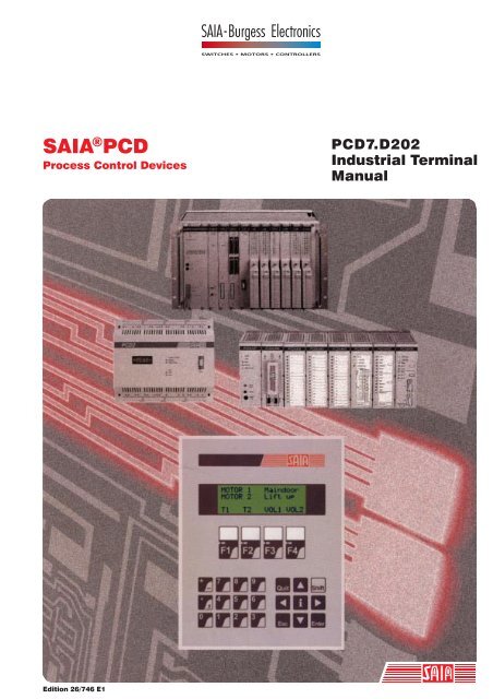
SAIA ® PCD<br />
Process Control Devices<br />
PCD7.D202<br />
Industrial Terminal<br />
Manual<br />
Edition 26/746 E1
Saia-Burgess Controls Ltd.<br />
Bahnhofstrasse 18<br />
CH-3280 Murten (Switzerland)<br />
http;//www.saia-burgess.com<br />
Telephone 026 / 672 72 72<br />
Telefax 026 / 672 74 99<br />
___________________________________________________________________________________________________________________________<br />
Saia-Burgess Companies<br />
Switzerland<br />
Saia-Burgess Controls Ltd.<br />
Bahnhofstrasse 18<br />
CH-3280 Murten<br />
026 672 72 72, Fax 026 672 74 99<br />
France<br />
SAIA-Burgess Electronics Sàrl.<br />
10, Bld. Louise Michel<br />
F-92230 Gennevilliers<br />
01 46 88 07 70, Fax 01 46 88 07 99<br />
Germany<br />
Saia-Burgess Dreieich GmbH & Co. KG<br />
Otto-Hahn-Strasse 31 - 33<br />
D-63303 Dreieich<br />
06103 89 060, Fax 06103 89 06 66<br />
Nederlands<br />
Saia-Burgess Benelux B.V.<br />
Hanzeweg 12c<br />
NL-2803 MC Gouda<br />
0182 54 31 54, Fax 0182 54 31 51<br />
Austria<br />
Saia-Burgess Österreich GmbH<br />
Schallmooser Hauptstrasse 38<br />
A-5020 Salzburg<br />
0662 88 49 10, Fax 0662 88 49 10 11<br />
Belgium<br />
SAIA-Burgess Electronics Belgium<br />
Avenue Roi Albert 1er, 50<br />
B-1780 Wemmel<br />
02 456 06 20, Fax 02 460 50 44<br />
Italy<br />
SAIA-Burgess Electronics S.r.l.<br />
Via Cadamosto 3<br />
I-20094 Corsico MI<br />
02 48 69 21, Fax 02 48 60 06 92<br />
Hungary<br />
SAIA-Burgess Electronics Automation Kft.<br />
Liget utca 1.<br />
H-2040 Budaörs<br />
23 501 170, Fax 23 501 180<br />
Representatives<br />
Great Britain<br />
Canham Controls Ltd.<br />
25 Fenlake Business Centre, Fengate<br />
Peterborough PE1 5BQ UK<br />
01733 89 44 89, Fax 01733 89 44 88<br />
Portugal<br />
INFOCONTROL Electronica e Automatismo, LDA<br />
Praceta Cesário Verde, No 10 S/Cave,<br />
P-2745-740 Massamá<br />
21 430 08 24, Fax 21 430 08 04<br />
Denmark<br />
Malthe Winje Automation AS<br />
Håndværkerbyen 57 B<br />
DK-2670 Greve<br />
70 20 52 01, Fax 70 20 52 02<br />
Spain<br />
Tecnosistemas Medioambientales, S.L.<br />
Ribadavia, 4, 8.°C<br />
E-28029 Madrid<br />
91 740 55 99, Fax 91 740 55 99<br />
Norway<br />
Malthe Winje Automasjon AS<br />
Haukelivn 48<br />
N-1415 Oppegård<br />
66 99 61 00, Fax 66 99 61 01<br />
Czech<br />
Republic<br />
ICS Industrie Control Service, s.r.o.<br />
Modranská 43<br />
CZ-14700 Praha 4<br />
2 44 06 22 79, Fax 2 44 46 08 57<br />
Sweden<br />
Malthe Winje Automation AB<br />
Truckvägen 14A<br />
S-194 52 Upplands Våsby<br />
08 795 59 10, Fax 08 795 59 20<br />
Poland<br />
SABUR Ltd.<br />
ul. Druzynowa 3A<br />
PL-02-590 Warszawa<br />
22 844 63 70, Fax 22 844 75 20<br />
Suomi/<br />
Finland<br />
ENERGEL OY<br />
Atomitie 1<br />
FIN-00370 Helsinki<br />
09 586 2066, Fax 09 586 2046<br />
Argentina<br />
MURTEN S.r.l.<br />
Av. del Libertador 184, 4° “A”<br />
RA-1001 Buenos Aires<br />
054 11 4312 0172, Fax 054 11 4312 0172<br />
After sales service<br />
USA<br />
SAIA-Burgess Electronics Inc.<br />
1335 Barclay Boulevard<br />
Buffalo Grove, IL 60089, USA<br />
847 215 96 00, Fax 847 215 96 06<br />
___________________________________________________________________________________________________________________________<br />
Edition : 18.04.2001<br />
Subjet to change without notice<br />
© Saia-Burgess Controls Ltd.
SAIA ® Programmable Control Devices<br />
Manual<br />
Industrial terminal<br />
PCD7.D202<br />
Saia-Burgess Controls Ltd.. All rights reserved<br />
Edition 26/746 E1 - 04.01<br />
Subject to technical changes<br />
© Saia-Burgess Controls Ltd.
Updates<br />
Manual :<br />
Industrial terminal PCD7.D202 - Edition E1<br />
Date Chapter Page Description<br />
20.11.2000 --- --- Small updates for the “Support Homepage”<br />
20.11.2000 --- --- Small updates for ..D202 (replaced ..D200)<br />
23.03.2001 10 10-2 Minor corrections<br />
30.04.2001 6 6-9 Correction of commands High/Low contrast<br />
© Saia-Burgess Controls Ltd.
PCD7.D202<br />
Contents<br />
Contents<br />
Page<br />
1. Application<br />
2. Technical data<br />
3. Dimensions<br />
4. Hardware<br />
4.1 Power supply / connector 4-1<br />
4.2 Firmware 4-1<br />
4.3 Serial interface RS 232 4-2<br />
5. Operation<br />
5.1 Power-up tests 5-1<br />
5.2 The keyboard 5-2<br />
5.3 Setup/Test mode 5-4<br />
6. Commands<br />
6.1 Configuration (by the serial interface) 6-1<br />
6.2 Cursor control 6-3<br />
6.3 Display control 6-5<br />
6.4 LED control 6-6<br />
6.5 Miscellaneous commands 6-7<br />
6.6 Command Summary 6-8<br />
7. Character sets<br />
7.1 First ASCII-table (32 ... 127 dec) 7-1<br />
7.2 Extended ASCII-table (128 ... 255 dec) 7-1<br />
8. User program examples for the PCD<br />
8.1 Hardware configuration 8-1<br />
8.2 Single text transmission 8-1<br />
8.3 Transmission of several texts 8-2<br />
8.4 Recognition of a pressed key with a following action 8-2<br />
8.5 Entering numerical parameters 8-3<br />
9. Comparison of terminals PCD7.D100 and ..D202<br />
10. Interface connection cables RS 232<br />
26/746 E1 (D2-00-E.DOC) © SAIA AG Page 1
Contents<br />
PCD7.D202<br />
Notes :<br />
Page 2 © SAIA AG (D2-00-E.DOC) 26/746 E1
PCD7.D202<br />
Contents<br />
Please note :<br />
A number of detailed manuals are available to aid installation and<br />
operation of the SAIA ® PCD. These are for use by technically<br />
qualified staff, who may also have successfully completed one of our<br />
"workshops".<br />
To obtain the best performance from your SAIA ® PCD, closely follow<br />
the guidelines for assembly, wiring, programming and commissioning<br />
given in these manuals. In this way, you will also become one of the<br />
many enthusiastic SAIA ® PCD users.<br />
If you have any technical suggestions or recommendations for<br />
improvements to the manuals, please let us know. A form is provided<br />
on the last page of this manual for your comments.<br />
Summary<br />
PCD1/2 series PCD4 series PCD6 series<br />
Hardware<br />
PCD1<br />
PCD2<br />
Serie xx7<br />
Hardware<br />
PCD4<br />
PCD4.H1..<br />
*)<br />
Hardware<br />
PCD6<br />
PCD2.M250<br />
General<br />
Manuals<br />
PCD2.H110<br />
PCD2.H150<br />
PCD2.H210<br />
PCD2.H31x<br />
PCD4.H2..<br />
PCD4.H3..<br />
*)<br />
PCD4.H4..<br />
*)<br />
*) Adapter module 4'717'4828'0<br />
allows H modules to be used<br />
with the PCD6.<br />
User's<br />
Guide<br />
Reference<br />
Guide<br />
(PG3)<br />
PCD8.P1..<br />
- PCD7.D1..<br />
- PCD7.D202<br />
- PCD7.D250<br />
- PCD7.D7..<br />
- S-Bus<br />
- LON<br />
- PROFIBUS<br />
Installation<br />
Components<br />
for RS 485-<br />
Networks<br />
- PG4<br />
- Modem<br />
FUPLA/<br />
KOPLA<br />
function<br />
families<br />
26/746 E1 (D2-00-E.DOC) © SAIA AG Page 3
Contents<br />
PCD7.D202<br />
Reliability and safety of electronic controllers<br />
Saia-Burgess Controls Ltd. is a company which devotes the greatest<br />
care to the design, development and manufacture of its products:<br />
• state-of-the-art technology<br />
• compliance with standards<br />
• ISO 9001 certification<br />
• international approvals: e.g. Germanischer Lloyd, UL,<br />
Det Norske Veritas, CE mark ...<br />
• choice of high-quality componentry<br />
• quality control checks at various stages of production<br />
• in-circuit tests<br />
Despite every care, the excellent quality which results from this does<br />
have its limits. It is therefore necessary, for example, to reckon with the<br />
natural failure of components. For this reason Saia-Burgess Controls<br />
Ltd. provides a guarantee according to the “General terms and conditions<br />
of supply”.<br />
The plant engineer must in turn also contribute his share to the reliable<br />
operation of an installation. He is therefore responsible for ensuring that<br />
controller use conforms to the technical data and that no excessive<br />
stresses are placed on it, e.g. with regard to temperature ranges,<br />
overvoltages and noise fields or mechanical stresses.<br />
In addition, the plant engineer is also responsible for ensuring that a<br />
faulty product in no case leads to personal injury or even death, nor to the<br />
damage or destruction of property. The relevant safety regulations should<br />
always be observed. Dangerous faults must be recognized by additional<br />
measures and any consequences prevented. For example, outputs which<br />
are important for safety should lead back to inputs and be monitored<br />
from software. Consistent use should be made of the diagnostic elements<br />
of the PCD, such as the watchdog, exception organization blocks (XOB)<br />
and test or diagnostic instructions.<br />
If all these points are taken into consideration, the SAIA ® PCD will<br />
provide you with a modern, safe programmable controller to control,<br />
regulate and monitor your installation with reliability for many years.<br />
Page 4 © Saia-Burgess Controls AG (D2-00-E.DOC_0401) 26/746 E1
Application<br />
1. Application<br />
The new PCD7.D... control terminals have been developed for tough<br />
industrial use, such as occurs in direct contact with production<br />
machines. In combination with the intelligent text output of the SAIA°<br />
PCD, it provides a simple way of implementing menu-driven user<br />
prompting.<br />
With the latest high contrast back-lit LC display, the PCD7.D202<br />
model can display any type of information such a temperature,<br />
pressure, unit numbers, date, time, etc., or messages about operating<br />
states or alarms.<br />
Under the abrasion-proof polyester foil there are 25 tactile feedback<br />
keys, enabling any necessary operating data or processing functions to<br />
be entered via the serial data interface, prompted by a menu controlled<br />
by the SAIA° PCD.<br />
Labelling strips can be slid beneath the partially transparent front-panel<br />
foil: a simple way of enabling the user to create personalized key labels<br />
whenever required. Due to the arrangement of the function keys<br />
directly below the display, these can also be used as soft keys.<br />
Quick guide to operating the PCD7.D202 terminal<br />
The following chapters supply detailed descriptions of the broad<br />
functional possibilities provided by the D202 terminal. In any practical<br />
application, probably only a small part of them will be used.<br />
In order to give the beginner a brief guide to simple text output it is<br />
advisable, before studying all tests and instructions individually, to do<br />
one of the program examples from chapter 8 as a practical exercise.<br />
In this way it will be obvious how simple it is in practice to work with<br />
the PCD and the D202 terminal.<br />
Issue 02.96<br />
© SAIA AG<br />
page 1-1
Application<br />
Notes :<br />
Page 1-2 © SAIA AG Issue 02.96
Technical data<br />
2. Technical data<br />
Function data<br />
Display<br />
Keyboard<br />
Data interface<br />
LC-display, supertwist with LED back lighting,<br />
4 x 20 characters, height 4.75 mm, with cursor<br />
Character set: ASCII characters 16 to 127 and control<br />
functions plus special characters depending on language,<br />
4 x LEDs to left of LC-display<br />
Foil keyboard with tactile feedback<br />
Numeric keypad with 12 keys, 15 mm spacing<br />
Control keypad with 9 keys, 15 mm spacing<br />
4 function keys, 19 mm spacing, with red LEDs and<br />
slide-in labelling strip<br />
Communications interface (for SAIA°PCD)<br />
COM 1: RS 232 (fixed)<br />
Transmission speed: 110... 19200 bps<br />
Electrical data<br />
Supply voltage<br />
Power<br />
consumption<br />
Connection<br />
EMC<br />
19... 32 VDC, smoothed, with reserve battery protection,<br />
or<br />
19 VAC +/- 15 %, full-wave rectified, with reverse<br />
battery protection<br />
max.0.2 A at 24 VDC<br />
Power supply via plug-in screw terminals for wires of<br />
max. 2.5 mm 2<br />
Data interface via 9-pole D-type jack<br />
ESD complies IEC 801-2: 6 kV (HVR) or 8 kV<br />
(discharge)<br />
Burst complies IEC 801-4: power supply 4 kV direct,<br />
data interfaces 1 kV capacitive<br />
Emission complies EN 55022 class B<br />
General data<br />
Housing<br />
Ambient<br />
temperature<br />
Plastic frame with polyester foil, front panel protection<br />
IP 65<br />
Backplate in aluminium sheet<br />
See dimension drawing for measurements and control<br />
panel cutout<br />
Mounting with stud bolts<br />
Operation 0...50 °C (as option -20...+70 °C)<br />
Storage -25...+70 °C (as option -30...+80 °C)<br />
Issue 02.96<br />
© SAIA AG<br />
page 2-1
Technical data<br />
Atmospheric<br />
humidity<br />
5...95 % relative humidity without condensation,<br />
according to IEC 1131-2 and DIN 40 040 class F<br />
Mechanical Vibration 10...57 Hz, 0.075 mm or<br />
resistance 57...150 Hz, 1.0 g according to IEC 68-2-6<br />
page 2-2 © SAIA AG<br />
Issue 02.96
Dimensions<br />
3. Dimensions<br />
Panel cutout<br />
Mounting with stud<br />
bolts<br />
Issue 02.96<br />
© SAIA AG<br />
page 3-1
Dimensions<br />
Notes :<br />
Page 3-2 © SAIA AG Issue 02.96
Power supply and connector<br />
Hardware<br />
4. Hardware<br />
4.1 Power supply / connector<br />
A<br />
Power supply via plug-in screw terminals for wires of max.<br />
2.5 mm 2 (flexible wires with ferrules max. 1.5 mm 2 ).<br />
19...32 VDC smoothed or 19 VAC ± 15 % full wave<br />
rectified with reverse battery protection.<br />
!<br />
A good earth connection is imperative for perfect<br />
operation! Moreover, whenever the cover has been<br />
removed, cover screw S must be screwed back<br />
tightly to restore a good connection to frame<br />
ground.<br />
S<br />
The labelling strip for the 4 function keys is inserted at<br />
point A.<br />
Power supply with full wave rectified AC<br />
PCD7.D2..<br />
External supply<br />
electronic cutout<br />
Overvoltage limiter<br />
noise filter<br />
reverse battery protection<br />
smoothing<br />
4.2 Firmware<br />
The Firmware is stored on an EPROM. To update the firmware remove<br />
the cover by pressing on the two latches (see part 4.1).<br />
Issue 02.96<br />
© SAIA AG<br />
page 4-1
Hardware<br />
Serial interface RS232<br />
4.3 Serial interface RS232<br />
via 9-pole D-type jack (COM 1)<br />
4.3.1 Without RTS/CTS handshaking, or with XON/XOFF<br />
Instructions apply for all PCD communications channels:<br />
- At the terminal, RTS must be connected with CTS.<br />
- Up to 9600 Baud it is possible to work under PCD communications<br />
mode MC0.<br />
- If communication is at 19,200 Baud, handshaking with XON/XOFF<br />
is required (PCD communications mode MC2).<br />
a) D202 terminal to PGU connector of PCD<br />
Terminal PCD7.D202<br />
COM1<br />
cable<br />
PCD processor module<br />
at PGU socket<br />
interface 0<br />
TxD 2<br />
RxD 3<br />
SGND 5<br />
CTS 7<br />
2 RxD<br />
3 TxD<br />
5 SGND<br />
7 RTS<br />
RTS 8<br />
PGND 1<br />
*)<br />
8 CTS<br />
1 PGND<br />
Shield /<br />
housing<br />
*) optional connection<br />
Shield /<br />
housing<br />
PCD7.K412 cable can be used for this connection (see chapter 10).<br />
page 4-2<br />
© SAIA AG<br />
Issue 02.96
Serial interface RS232<br />
Hardware<br />
b) D202 terminal to PCD processors, channels 1 to 3<br />
Terminal<br />
PCD7.D202<br />
COM1<br />
cable<br />
PCD processor module<br />
PCD7.<br />
F120<br />
PCD2.<br />
F5..<br />
PCD4.<br />
C120<br />
PCD4.<br />
C130<br />
TxD 2<br />
RxD<br />
12<br />
32<br />
11<br />
31<br />
RxD 3<br />
TxD<br />
11<br />
31<br />
10<br />
30<br />
SGND 5<br />
CTS 7<br />
RTS 8<br />
RTS<br />
CTS<br />
Channel 1<br />
Channel 2<br />
Channel 1<br />
Channel 3<br />
PGND 1<br />
Shield / housing<br />
GND<br />
10<br />
(-)<br />
30<br />
(-)<br />
GND<br />
(-)<br />
GND<br />
(-)<br />
PCD7.K422 cable can be used for this connection (see chapter 10).<br />
4.3.2 With RTS/CTS handshaking<br />
The corresponding PCD communications channel must be assigned<br />
with MC1 mode.<br />
Terminal<br />
PCD7.D202<br />
COM1<br />
cable<br />
PCD processor module<br />
PCD7. PCD2. PCD4.<br />
F120 F5.. C120<br />
PCD4.<br />
C130<br />
TxD 2<br />
RxD<br />
12<br />
32<br />
11<br />
31<br />
RxD 3<br />
TxD<br />
11<br />
31<br />
10<br />
30<br />
SGND 5<br />
CTS 7<br />
RTS<br />
13<br />
33<br />
14<br />
34<br />
RTS 8<br />
CTS<br />
14<br />
34<br />
15<br />
35<br />
PGND 1<br />
Shield / housing<br />
GND<br />
10<br />
(-)<br />
30<br />
(-)<br />
GND<br />
(-)<br />
GND<br />
(-)<br />
Issue 02.96<br />
© SAIA AG<br />
page 4-3
Hardware<br />
Serial interface RS232<br />
Notes :<br />
Page 4-4 © SAIA AG Issue 02.96
Power-up tests<br />
Operation<br />
5. Operation<br />
5.1 Power-up tests<br />
When the D202 starts up, this display is shown:<br />
SAIA AG, 3280 MURTEN<br />
PCD7.D202 V001<br />
POWER-UP TEST<br />
The power-up tests are executed, and the D202 is initialized.<br />
This takes about 3 seconds. The user program should not send<br />
commands to the D202 during this period, because they will be<br />
ignored. The user program can use the "poll D202" command,<br />
described in section 6.5, to determine when the D202 is ready to accept<br />
commands, or can simply delay for short period.<br />
If any test fails, the D202 attempts to indicate the failure on the display<br />
and the D202's microprocessor is halted. The tests are automatically<br />
repeated after about 1.5 seconds, when the watchdog timer resets the<br />
D202.<br />
At the start of each test a single LED is turned on.<br />
Power-up test indication on LEDs<br />
not used<br />
LED 5<br />
SAIA AG, 3280 MURTEN<br />
PCD7.D202 V001<br />
POWER-UP TEST<br />
LCD initializing<br />
F1 F2 F3 F4<br />
LED1 LED2 LED3 LED4<br />
ALL LED ON = CPU Test<br />
EEPROM test<br />
LC-display test<br />
EPROM test<br />
RAM test<br />
If all LEDs remain permanently lit, it means that the microprocessor<br />
cannot run or is faulty.<br />
Issue 02.96<br />
© SAIA AG<br />
page 5-1
Operation<br />
The keyboard<br />
5.2 The keyboard<br />
The D202 has a membrane keyboard which is compatible with the<br />
D100 terminal's keyboard.<br />
Returned key codes are:<br />
Key<br />
Dec<br />
Hex<br />
ASCII<br />
Notes<br />
F1<br />
F2<br />
F3<br />
F4<br />
65<br />
66<br />
67<br />
68<br />
41<br />
42<br />
43<br />
44<br />
'A'<br />
'B'<br />
'C'<br />
'D'<br />
0<br />
1<br />
2<br />
3<br />
4<br />
5<br />
6<br />
7<br />
8<br />
9<br />
+<br />
-<br />
.<br />
,<br />
48<br />
49<br />
50<br />
51<br />
52<br />
53<br />
54<br />
55<br />
56<br />
57<br />
43<br />
45<br />
46<br />
44<br />
30<br />
31<br />
32<br />
33<br />
34<br />
35<br />
36<br />
37<br />
38<br />
39<br />
2B<br />
2D<br />
2E<br />
2C<br />
'0'<br />
'1'<br />
'2'<br />
'3'<br />
'4'<br />
'5'<br />
'6'<br />
'7'<br />
'8'<br />
'9'<br />
'+'<br />
'-'<br />
'.'<br />
','<br />
Shift+'+'<br />
Shift+'.'<br />
page 5-2 © SAIA AG<br />
Issue 02.96
The keyboard<br />
Operation<br />
Key<br />
Dec<br />
Hex<br />
ASCII<br />
Notes<br />
i<br />
Quit<br />
Shift<br />
Esc<br />
↵<br />
↑<br />
↓<br />
←<br />
→<br />
105<br />
113<br />
-<br />
27<br />
13<br />
11<br />
5<br />
8<br />
6<br />
69<br />
71<br />
-<br />
1B<br />
0D<br />
0B<br />
05<br />
08<br />
06<br />
"i"<br />
'q'<br />
-<br />
ESC<br />
CR<br />
VT<br />
ENQ<br />
BS<br />
ACK<br />
*<br />
*<br />
Information<br />
Quit<br />
No code returned<br />
Escape<br />
Carraiage return (enter)<br />
Up arrow<br />
Down arrow<br />
Left arrow<br />
Right arrow<br />
Shift + F1<br />
Shift + F2<br />
Shift + F3<br />
Shift + F4<br />
119<br />
120<br />
121<br />
122<br />
77<br />
78<br />
79<br />
7A<br />
'w'<br />
'x'<br />
'y'<br />
'z'<br />
Shifted states of function keys<br />
Shift+0<br />
Shift+1<br />
Shift+2<br />
Shift+3<br />
Shift+4<br />
Shift+5<br />
Shift+6<br />
Shift+7<br />
Shift+8<br />
Shift+9<br />
97<br />
98<br />
99<br />
100<br />
101<br />
102<br />
103<br />
104<br />
106<br />
107<br />
61<br />
62<br />
63<br />
64<br />
65<br />
66<br />
67<br />
68<br />
6A<br />
6B<br />
'a'<br />
'b'<br />
'c'<br />
'd'<br />
'e'<br />
'f'<br />
'g'<br />
'h'<br />
'j'<br />
'k'<br />
*<br />
*<br />
Shifted states of numeric keys<br />
Shift+i<br />
-<br />
-<br />
-<br />
Enters "Setup/Test mode", no code is<br />
output.<br />
Shift + Quit<br />
bis<br />
Shift + →<br />
Same codes as without Shift<br />
*) These four codes have changed from prov. Firmware version β1.0 to the def. version V001<br />
(see appendix 1).<br />
Issue 02.96<br />
© SAIA AG<br />
page 5-3
Operation<br />
Setup/Test mode<br />
5.3 Setup/Test mode<br />
This mode is entered by pressing Shift+i on the D202 keyboard.<br />
Setup/Test mode can be entered when the D202 on or off line, all data<br />
received from the host is ignored until the mode is exited.<br />
SETUP/TEST MODE<br />
↑ or ↓ scrolls menu<br />
↵ executes,<br />
ESC exits Setup mode<br />
Prompt text<br />
Scrolling menu<br />
Pressing the up or down arrow key steps through the Setup/Test mode<br />
menu:<br />
Setup mode<br />
Default setup<br />
Demo display<br />
Hardware tests<br />
Display test<br />
Keyboard test<br />
LED test<br />
Configures the D202<br />
Restores factory default setup<br />
Demonstration display<br />
Runs hardware tests continuously<br />
Tests the LCD display<br />
Tests the keyboard<br />
Tests the LEDs<br />
Once the desired menu item is selected, pressing ↵ (carriage return)<br />
executes.<br />
To exit Setup/Test mode, press "Quit" or "Esc".<br />
!<br />
Note:<br />
If the host computer is sending data to the D202 when the<br />
operator enters Setup/Test mode, characters may be lost,<br />
which can cause the display to become corrupted on return<br />
to normal operation.<br />
page 5-4<br />
© SAIA AG<br />
Issue 02.96
Setup/Test mode<br />
Operation<br />
5.3.1 Setup mode<br />
This displays and configures the setup data in the non-volatile<br />
EEPROM. The first screen shows a help text:<br />
SETUP MODE<br />
↑ or ↓ scrolls menu<br />
← or → changes data<br />
↵ accepts,ESC aborts<br />
Pressing any key displays the first item in the menu:<br />
SETUP MODE<br />
Baudrate:<br />
9600<br />
Pressing the up or down arrow key steps through the menu of<br />
configurable items:<br />
Baudrate 110, 150, 300, 600, 1200, 2400, 4800<br />
[9600], 19200<br />
Data bits [8], 7<br />
Parity<br />
[Even], Odd, None, Low<br />
Stop bits [1], 2<br />
Handshaking [None], RTS/CTS, XON/XOFF<br />
Echo key to display [No], Yes<br />
Page/scroll mode [Page], Scroll<br />
Auto line feed [No], Yes<br />
Key auto-repeat [No], All keys, All keys 2 speed,<br />
Arrow keys, Arrow keys 2 speed.<br />
Character set [D100 compatible], English, French,<br />
German, Scandinavian<br />
Backlight<br />
[On], Off<br />
Contrast 0... 15 [7]<br />
[ ] Factory default settings are shown in square brackets. Each item is<br />
described in detail below.<br />
Press the left or right arrow key to change the selected item's setting.<br />
For the baudrate example above, the left/right arrow keys step through<br />
the list of available baudrates (110..19200).<br />
Once all settings are correct, press ↵ (carriage return) to store the data<br />
to the non-volatile EEPROM memory. To abort, discarding any<br />
changes, press "Quit" or "Esc".<br />
All features except the baudrate, data bits, parity, stop bits and<br />
handshaking can also be controlled from the host computer by sending<br />
an escape sequence to the D202. These are described in section 6.1.<br />
Issue 02.96<br />
© SAIA AG<br />
page 5-5
Operation<br />
Setup/Test mode<br />
Communication parameter<br />
(Baudrate, Data bits, Parity and<br />
Stop bits)<br />
These settings define the communications protocol<br />
1 Startbit<br />
7 or 8 Data bits<br />
1 Parity bit (or none)<br />
1 or 2 Stop bits<br />
If "High" parity is required, this can be simulated by setting the parity<br />
to "None" and using 2 stop bits. This is the same as high parity and one<br />
stop bit.<br />
Handshaking<br />
[None]<br />
"Handshaking" refers to the signalling between the host computer and<br />
the D202 which indicates when the unit is ready to receive and process<br />
data on the serial line. If data and commands are sent to the D202 faster<br />
than it can process them, it can use handshaking to prevent the host<br />
computer sending more data until it is ready for it. The host can also<br />
prevent the D202 sending key depressions until it is ready to process<br />
them.<br />
Normally handshaking is not required because the D202 can process<br />
incoming data very fast and also has a 512 character receive buffer.<br />
The high baudrate 19200 always requires a handshaking (either<br />
RTS/CTS or XON/XOFF).<br />
RTS/CTS :<br />
XON/XOFF :<br />
This handshaking uses the RTS (Request To Send)<br />
and CTS (Clear To Send) lines for the handshaking.<br />
The host must not send data to the D202 when the<br />
CTS output from the D202 is false. The D202 will not<br />
send key depressions to the host if the CTS output<br />
from the host is false (key depressions are buffered<br />
until CTS goes true). RTS/CTS must be connected as<br />
shown in the second diagram in section 4.3 and the<br />
SAIA° PCD is assigned in mode MC1.<br />
handshaking uses the XOFF (17 decimal, 11H) and<br />
XON (19 decimal, 13H) characters to disable (XOFF)<br />
and enable (XON) transmission. Pins 7 and 8 of the<br />
terminal plug must be connected together and SAIA°<br />
PCD is assigned in mode MC2.<br />
page 5-6<br />
© SAIA AG<br />
Issue 02.96
Setup/Test mode<br />
Operation<br />
Echo (Echo key to display)<br />
[No]<br />
When a key is pressed in "Echo=Off" mode (the default), the ASCII<br />
code is transmitted directly to the host computer and is not displayed.<br />
The user program in the host computer must echo the character back to<br />
the D202 for it to be displayed. When a key is pressed in "Echo=Yes"<br />
mode, the character is automatically written to the display at the current<br />
cursor position, and it is also transmitted to the host.<br />
Page/scroll mode<br />
[Page]<br />
Page mode :<br />
The cursor moves from the last line to the first line<br />
when the D202 receives a line feed character. The<br />
display is not altered.<br />
Scroll mode:<br />
If the cursor is on the last line when a line feed is<br />
received, then the display scrolls up one line and the<br />
cursor remains on the last line, which is now blank, in<br />
the same column. If the line feed was caused by a<br />
carriage return character, with "auto line feed" set to<br />
"Yes", then the cursor is also moved to the start of<br />
the line.<br />
Auto line feed<br />
[No]<br />
When the D202 receives a carriage return character (13 decimal, 0DH),<br />
it moves the cursor to the start of the current line. If "auto line feed" is<br />
set to "Yes", then the cursor also moves to the next line down automatically.<br />
If the cursor is on the last line, it moves to the first line or<br />
scrolls the display up one line according to the page/scroll mode. If<br />
auto line feed is "No", then a line feed character (10 decimal, 0AH)<br />
must be sent after the carriage return to achieve the same effect.<br />
Key auto-repeat<br />
[No]<br />
Keys can be made to repeat at a rate of 8 per second if the key is held<br />
depressed for more than 0.7 seconds. The auto-repeat feature has these<br />
settings:<br />
No<br />
All keys<br />
All keys "2 speed"<br />
Arrow keys<br />
Arrow keys "2 speed"<br />
No keys repeat (default)<br />
All keys repeat<br />
All keys repeat, with 2-speed signalling,<br />
see below<br />
Only the arrow keys repeat<br />
Only the arrow keys repeat, with 2 speed<br />
signalling, see below<br />
Issue 02.96<br />
© SAIA AG<br />
page 5-7
Operation<br />
Setup/Test mode<br />
"2 speed" signalling mode is for use by host programms that have<br />
stepping up/down controls, which are stepped by pressing up/down<br />
keys. With auto-repeat on, key codes are sent at a rate of 8 per second if<br />
the key is held down for 0.7 sec. The same occurs with the 2 speed<br />
feature, but after holding the key down for 3 seconds a special "start<br />
second speed" character (30 decimal) is sent to the host to indicate 2<br />
speed mode, followed by more repeated key codes at the same 8-persecond<br />
rate. When the key is released an "end 2 speed" character (31<br />
decimal) is sent to indicate that the key has been released.<br />
When the host's program receives the up/down key code, it should<br />
increment/decrement the associated value. If the host receives a "start<br />
second speed" character it should step the value by two (or more) and<br />
also for each additional up/down key code received and stop when the<br />
"end 2 speed" character is received (or any character which is not the<br />
same repeated up/down key code).<br />
For example, if "A" is pressed, with "All keys, 2 speed" auto-repeat,<br />
this is the sequence of events:<br />
Time (secs.)<br />
Code sent:<br />
0 0,7 3 n<br />
A AAAAA . . . AAAA 30AA . . . AA 31<br />
Start repeat at 8 per sec.<br />
"A" key pressed, single A sent.<br />
Key released,<br />
sends 31 decimal.<br />
Start second speed mode after 3 secs,<br />
sends 30 decimal, "A" still repeats at 8<br />
per second.<br />
Character set<br />
[D100]<br />
Five character sets are available. Each character set has the same<br />
characters for those with codes 32 to 127 decimal (20H to 7FH), but<br />
extended ASCII characters with codes 128 to 255 decimal (80H to<br />
FFH) are selected according to the character set. (see section 7).<br />
Backlight<br />
[On]<br />
The display's LED backlight can be turned off if required. The<br />
backlight is normally always on, and is required to make the text<br />
visible. The backlight is usually only turned off and on (blinked) to<br />
provide a visual indication of an alarm etc. using escape sequences sent<br />
by the host computer.<br />
page 5-8<br />
© SAIA AG<br />
Issue 02.96
Setup/Test mode<br />
Operation<br />
Contrast [7]<br />
The contrast of the LCD display (it's blackness) can be adjusted in 16<br />
steps by selecting a value between 0 and 15. 0 is the lightest, 15 is the<br />
darkest.<br />
5.3.2 Default setup<br />
This restores the factory default setup, and writes it into the nonvolatile<br />
EEPROM. The factory default settings are as follows:<br />
Baudrate 9600<br />
Data bits 8<br />
Parity<br />
Even<br />
Stop bits 1<br />
Echo key to display No<br />
Handshaking None<br />
Page/scroll mode Page<br />
Auto line feed No<br />
Key auto-repeat No<br />
Character set D100 compatible<br />
Backlight<br />
On<br />
Contrast<br />
7 (medium)<br />
5.3.3 Demo display<br />
This is for use when showing the D202 at an exhibition, when it is not<br />
connected to a host computer. The display shows some information<br />
about the unit. Press Shift+F4 to exit.<br />
-=< PCD7.D202 >=-<br />
INDUSTRIAL TERMINAL<br />
SAIA AG<br />
CH-3280 MURTEN<br />
5.3.4 Hardware tests<br />
This runs the power-up tests in a continuous loop, which can be used<br />
for detecting intermittent faults when the D202 is in the field. The tests<br />
run until an error occurs, which displays a text and the D202 is reset by<br />
the watchdog timer and the tests are repeated. The only way to exit the<br />
tests is to power the D202 off and on.<br />
Issue 02.96<br />
© SAIA AG<br />
page 5-9
Operation<br />
Setup/Test mode<br />
5.3.5 Display test<br />
This is a comprehensive test of the LCD display, the character set and<br />
the LCD controller's internal RAM. Press any key to exit.<br />
5.3.6 Keyboard test<br />
This displays a "map" of the keyboard, with a digit for each key. If the<br />
key is not pressed, the digit will be "0", when the key is pressed the<br />
digit should be "1". It also shows the character assigned to the last key<br />
which was pressed, enclosed in square brackets, e.g. [Q], [ESC]<br />
The map is organized in the same layout at the D202 keyboard:<br />
0000 [ESC] KEYBOARD<br />
0000 000 TEST<br />
0000 000 Shift+F4<br />
0000 100 exits<br />
Press Shift+F4 to exit the keyboard test.<br />
5.3.7 LED test<br />
Each LED in sequence is turned on for 500mS, and the display shows a<br />
'1' for the LED which should be on:<br />
green LED8 ⎯→<br />
orange LED7 ⎯→<br />
red LED6 ⎯→<br />
red LED5 ⎯→<br />
0 LED TEST<br />
0 Any key<br />
1 exits<br />
0 0 0 0 0<br />
LED4<br />
LED3<br />
LED2<br />
LED1<br />
red<br />
Press any key to end the test and return to Setup/Test mode.<br />
page 5-10<br />
© SAIA AG<br />
Issue 02.96
Configuration (by the serial interface)<br />
Commands<br />
6. Commands<br />
Single control characters or two, three or four character "escape<br />
sequences" are transmitted to the D202 using the PCD's STXT (send<br />
text) or STXD (transmit character) instructions.<br />
!<br />
Note:<br />
Some escape sequences use the '@' character. If using a<br />
SAIA° PCD port running in MODE C, the PCD interprets<br />
an '@' character as the start of an indirect addressing<br />
control string. So when using MODE C, enter each '@'<br />
character as '@@', so the PCD intreprets it as a single '@'<br />
character.<br />
6.1 Configuration (by the serial interface)<br />
The configuration of the D202 can be modified by sending a series of<br />
special commands. The configuration remains active until the D202 is<br />
powered off and on, whereupon the configuration defined from "setup<br />
mode" is restored.<br />
All required commands can be included in a single PCD Text and<br />
transmitted to the D202 in one go.<br />
Echo key to display<br />
See section 5.3.1 for details.<br />
Command ASCII Decimal Hex<br />
Echo off ESC @ 0 27 64 48 1B 40 30<br />
Echo on ESC @ 1 27 64 49 1B 40 31<br />
Page and scroll mode<br />
See section 5.3.1 for details.<br />
Command ASCII Decimal Hex<br />
Scroll mode ESC @ 4 27 64 52 1B 40 34<br />
Page mode ESC @ 5 27 64 53 1B 40 35<br />
Issue 02.96<br />
© SAIA AG<br />
page 6-1
Commands<br />
Configuration (by the serial interface)<br />
Auto line feed after carriage return<br />
See section 5.3.1 for details.<br />
Command ASCII Decimal Hex<br />
Auto line feed on ESC @ 2 27 64 50 1B 40 32<br />
Auto line feed off ESC @ 3 27 64 51 1B 40 33<br />
Key auto-repeat<br />
See section 5.3.1 for details.<br />
Command ASCII Decimal Hex<br />
Auto-repeat off ESC A 27 65 1B 41<br />
Auto-repeat on:<br />
• all keys ESC B 27 66 1B 42<br />
• arrow keys only ESC C 27 67 1B 43<br />
• all keys,<br />
"2 speed" ESC D 27 68 1B 44<br />
• arrow keys,<br />
"2 speed" ESC E 27 69 1B 45<br />
Character set<br />
Five character sets are available, as described in section 7.<br />
Command ASCII Decimal Hex<br />
D100 compatible ESC @ F 27 64 70 1B 40 46<br />
English ESC @ 6 27 64 54 1B 40 36<br />
French ESC @ 7 27 64 55 1B 40 37<br />
German ESC @ 8 27 64 56 1B 40 38<br />
Scandinavian ESC @ E 27 64 69 1B 40 45<br />
Backlight and contrast see part 6.3<br />
page 6-2<br />
© SAIA AG<br />
Issue 02.96
Cursor control<br />
Commands<br />
6.2 Cursor control<br />
Cursor up/down/left/right<br />
The cursor can be moved one place up, down, left or right with a singlecharacter<br />
command. These commands work in the same way for both<br />
scroll and page modes. If the cursor is moved off the display, it wraps<br />
around automatically. For example if the cursor is on the first line, a<br />
"cursor up" command moves it to the same column of the last line. If the<br />
cursor is on the last column, a "cursor right" command moves it to the start<br />
of the same line.<br />
Command ASCII Decimal Hex<br />
Cursor up CTRL+K 11 0B<br />
Cursor down CTRL+E 5 05<br />
Cursor left CTRL+H 8 08<br />
Cursor right CTRL+F 6 06<br />
Cursor positioning<br />
Apart from the cursor address code (16 dec. or 10H), this function also<br />
requires X and Y addresses to position the cursor. Add an offset of 32 dec.<br />
or 20H to both addresses. If either of the addresses is incorrect, the cursor<br />
is not moved.<br />
Example (sequence: 16 dec., Code X, Code Y) :<br />
Cursor position Decimal command Hex command<br />
Column 1, Line 1 16 32 32 10 20 20<br />
Column 4, Line 2 16 35 33 10 23 21<br />
Column 16, Line 4 16 47 35 10 2F 23<br />
Y<br />
X<br />
Code Code<br />
1<br />
2<br />
<br />
<br />
<br />
<br />
<br />
<br />
<br />
<br />
<br />
<br />
<br />
<br />
<br />
<br />
<br />
<br />
<br />
<br />
<br />
<br />
x<br />
1 2 3 4x<br />
5 6 7 8 9 10 11 12 13 14 15 16 17 18 19 20<br />
3<br />
4<br />
x<br />
Note:<br />
To place the cursor in x-pos. 36 (equal ASCII $), please enter in<br />
each PCD text .<br />
Example: TEXT xxxx "... 16 36 36 34 ..."<br />
x-pos y-pos<br />
Issue 02.96<br />
© SAIA AG<br />
page 6-3
Commands<br />
Cursor control<br />
Cursor home<br />
This single-character command moves the cursor to the first column of<br />
the first line.<br />
Command ASCII Decimal Hex<br />
Cursor home CTRL+Z 26 1A<br />
Cursor on/off<br />
These two-character commands turn the cursor on and off.<br />
Command ASCII Decimal Hex<br />
Cursor on ESC W 27 87 1B 57<br />
Cursor off ESC T 27 84 1B 54<br />
Line feed<br />
Line feed moves the cursor down one line. If the cursor was on the last<br />
line, this scrolls the display if in scroll mode, or the cursor moves to the<br />
first line if in page mode. The column position is not changed.<br />
Command ASCII Decimal Hex<br />
Line feed LF 10 0A<br />
Carriage return<br />
Carriage return moves the cursor to the start of the current line. If "auto<br />
line feed after carriage return" is selected, a line feed is also done as<br />
described above.<br />
Command ASCII Decimal Hex<br />
Carriage return CR 13 0D<br />
Delete character<br />
Delete removes the character to the left of the cursor (changes it to a<br />
space), and moves the cursor left one place. If at the start of a line, the<br />
cursor is moved to the end of the preceding line. Delete stops at the<br />
home position.<br />
Command ASCII Decimal Hex<br />
Delete (backspace) DEL 127 7F<br />
page 6-4 © SAIA AG<br />
Issue 02.96
Display control<br />
Commands<br />
6.3 Display control<br />
Clear display<br />
Clear display sets all the characters on the display to spaces, and moves<br />
the cursor to the home position.<br />
Command ASCII Decimal Hex<br />
Clear display CTRL+L 12 0C<br />
Save display/Restore display<br />
These commands save and restore the contents of the display and the<br />
cursor position and state (visible/not visible). Ten save/restore areas are<br />
provided, numbered 0 to 9. Restoring from a display area that was not<br />
previously saved will produce unexpected results.<br />
Command ASCII Decimal Hex<br />
Save display 'n' ESC @ S n 27 64 83 n 1B 40 53 n<br />
Restore display 'n' ESC @ R n 27 64 82 n 1B 40 52 n<br />
Where 'n' is '0'..'9' (48..57 decimal, 30H..39H)<br />
Backlight off/on<br />
The display's LED backlight can be turned off if required. The<br />
backlight is normally always on, and is required to make the text<br />
visible. The backlight can be turned off and on (blinked) to provide a<br />
visual indication of an alarm etc.<br />
Command ASCII Decimal Hex<br />
Backlight off ESC O 27 79 1B 4F<br />
Backlight on ESC L 27 76 1B 4C<br />
Display contrast<br />
The contrast of the LCD display (it's blackness) can be adjusted by<br />
sending a hex contrast value between 0 and F, where 0 is lightest and F<br />
is darkest.<br />
Command ASCII Decimal Hex<br />
High contrast ESC @ D 0 27 64 68 48 1B 40 44 30<br />
Medium contrast ESC @ D 7 27 64 68 55 1B 40 44 37<br />
Low contrast ESC @ D F 27 64 68 70 1B 40 44 46<br />
Issue 02.96<br />
© SAIA AG<br />
page 6-5
Commands<br />
LED control<br />
6.4 LED control<br />
The D202 has 8 LEDs, numbered 1 to 8, which can be used as generalpurpose<br />
indicators. Each can be turned on and off by a four character<br />
escape sequence. A lower case letter 'a' to 'h' is used to select LED 1 to<br />
8 ('a'= LED 1, 'h'= LED 8). To turn on the LED use '1', to turn it off use<br />
'0'.<br />
LED8 (h)<br />
LED7 (g)<br />
LED6 (f)<br />
LED5 (e)<br />
LED1 (a) LED2 (b) LED3 (c) LED4 (d)<br />
F1 F2 F3 F4<br />
Command ASCII Decimal Hex<br />
Turn on LED 1 ESC @ a 1 27 64 97 49 1B 40 61 31<br />
Turn off LED 1 ESC @ a 0 27 64 97 48 1B 40 61 30<br />
Turn on LED 2 ESC @ b 1 27 64 98 49 1B 40 62 31<br />
Turn off LED 2 ESC @ b 0 27 64 98 48 1B 40 62 30<br />
Turn on LED 3 ESC @ c 1 27 64 99 49 1B 40 63 31<br />
Turn off LED 3 ESC @ c 0 27 64 99 48 1B 40 63 30<br />
Turn on LED 4 ESC @ d 1 27 64 100 49 1B 40 64 31<br />
Turn off LED 4 ESC @ d 0 27 64 100 48 1B 40 64 30<br />
Turn on LED 5 ESC @ e 1 27 64 101 49 1B 40 65 31<br />
Turn off LED 5 ESC @ e 0 27 64 101 48 1B 40 65 30<br />
Turn on LED 6 ESC @ f 1 27 64 102 49 1B 40 66 31<br />
Turn off LED 6 ESC @ f 0 27 64 102 48 1B 40 66 30<br />
Turn on LED 7 ESC @ g 1 27 64 103 49 1B 40 67 31<br />
Turn off LED 7 ESC @ g 0 27 64 103 48 1B 40 67 30<br />
Turn on LED 8 ESC @ h 1 27 64 104 49 1B 40 68 31<br />
Turn off LED 8 ESC @ h 0 27 64 104 48 1B 40 68 30<br />
LED colours: LED 1 to 6 red<br />
LED 7 orange<br />
LED 8 green<br />
page 6-6<br />
© SAIA AG<br />
Isuue 02.96
Miscellaneous commands<br />
Commands<br />
6.5 Miscellaneous commands<br />
Lock keyboard/Unlock keyboard<br />
These commands enable or disable the keyboard. When locked, all key<br />
depressions are ignored.<br />
Command ASCII Decimal Hex<br />
Lock keyboard ESC N 27 78 1B 4E<br />
Unlock keyboard ESC Q 27 81 1B 51<br />
Restart warm/ Restart cold<br />
"Restart warm" resets the D202 and restores the customer setup. It is<br />
the same as a power-up reset.<br />
"Restart cold" initializes the setup to the factory defaults listed in<br />
section 5.3.2.<br />
Command ASCII Decimal Hex<br />
Restart warm ESC H 27 72 1B 48<br />
Restart cold ESC @ G 27 64 71 1B 40 47<br />
Disable and Enable Setup/Test mode<br />
Once the D202 has been configured, you may want to prevent<br />
unautorized users changing the setup. This can be done with the escape<br />
sequence below, which disables or enables the Shift+i key combination.<br />
If desabled, Shift+i is also restored by powering the D202 off and on,<br />
or by sending a "Restart" command.<br />
Command ASCII Decimal Hex<br />
Disable Setup/Test ESC @ H 27 64 72 1B 40 48<br />
Enable Setup/Test ESC @ I 27 64 73 1B 40 49<br />
Demonstration display and hardware tests<br />
These commands execute the tests described in sections 5.3.3 to 5.3.7.<br />
The "poll D202" command can be used determine when test has been<br />
completed.<br />
Command ASCII Decimal Hex<br />
Demonstration display ESC J 27 74 1B 4A<br />
Display test ESC @ A 27 64 65 1B 40 41<br />
Keyboard test ESC @ 9 27 64 57 1B 40 39<br />
LED test ESC @ L 27 64 76 1B 40 4C<br />
Hardware tests ESC @ C 27 64 67 1B 40 43<br />
Issue 02.96<br />
© SAIA AG<br />
page 6-7
Commands<br />
Miscellaneous commands<br />
Poll<br />
To determine if the D202 is connected and is ready to receive<br />
commands, the "poll" message can be sent. If the D202 is ready, it<br />
returns an "SOH" response character (1 decimal, 01H). If not ready<br />
there will be no response. This is typically used to determine when the<br />
D202 has finished its power-up tests.<br />
The poll command is the only command which has a response. It can<br />
also be used to check that the D202 is still operational. If it fails, the<br />
user program could take the necessary action to alert the operator that<br />
the D202 terminal is not responding.<br />
Command ASCII Decimal Hex<br />
Poll ESC @ B 27 64 66 1B 40 42<br />
6.6 Command Summary<br />
Command ASCII Decimal Hex<br />
Configuration:<br />
Echo off ESC @ 0 27 64 48 1B 40 30<br />
Echo on ESC @ 1 27 64 49 1B 40 31<br />
Auto line feed on ESC @ 2 27 64 50 1B 40 32<br />
Auto line feed off ESC @ 3 27 64 51 1B 40 33<br />
Scroll mode ESC @ 4 27 64 52 1B 40 34<br />
Page mode ESC @ 5 27 64 53 1B 40 35<br />
D100 character set ESC @ F 27 64 70 1B 40 46<br />
English ESC @ 6 27 64 54 1B 40 36<br />
French ESC @ 7 27 64 55 1B 40 37<br />
German ESC @ 8 27 64 56 1B 40 38<br />
Scandinavian ESC @ E 27 64 69 1B 40 45<br />
Note: To output the character "@", please enter in each PCD text "@@" !<br />
page 6-8 © SAIA AG<br />
Issue 02.96
Command summary<br />
Commands<br />
Command ASCII Decimal Hex<br />
Auto-repeat off ESC A 27 65 1B 41<br />
Auto-repeat on:<br />
• all keys ESC B 27 66 1B 42<br />
• arrow keys only ESC C 27 67 1B 43<br />
• all keys, "2 speed" ESC D 27 68 1B 44<br />
• arrow keys, "2 speed" ESC E 27 69 1B 45<br />
Cursor control:<br />
Cursor up CTRL+K 11 0B<br />
Cursor down CTRL+E 5 05<br />
Cursor left CTRL+H 8 08<br />
Cursor right CTRL+F 6 06<br />
Cursor home CTRL+Z 26 1A<br />
Cursor on ESC W 27 87 1B 57<br />
Cursor off ESC T 27 84 1B 54<br />
Line feed LF 10 0A<br />
Carriage return CR 13 0D<br />
Delete (backspace) DEL 127 7F<br />
Cursor positioning ASCII CTRL+P ' '+X ' '+Y<br />
Decimal 16 32+X 32+Y<br />
Hex 10 20+X 20+Y<br />
Display control:<br />
Clear display CTRL+L 12 0C<br />
Save display 'n' ESC @ S n 27 64 83 n 1B 40 53 n<br />
Restore display 'n' ESC @ R n 27 64 82 n 1B 40 52 n<br />
Backlight off ESC O 27 79 1B 4F<br />
Backlight on ESC L 27 76 1B 4C<br />
Low contrast ESC @ D 0 27 64 68 48 1B 40 44 30<br />
Medium contrast ESC @ D 7 27 64 68 55 1B 40 44 37<br />
High contrast ESC @ D F 27 64 68 70 1B 40 44 46<br />
LED control:<br />
Turn on LED 1 ESC @ a 1 27 64 97 49 1B 40 61 31<br />
Turn off LED 1 ESC @ a 0 27 64 97 48 1B 40 61 30<br />
(for other LEDs: 'b'=2, 'c'=3, 'd'=4, 'e'=5, 'f'=6, 'g'=7, 'h'=8)<br />
Note: To output the character "@", please enter in each PCD text "@@" !<br />
Issue 04.01<br />
© Saia-Burgess Controls AG<br />
page 6-9
Commands<br />
Command summary<br />
Command ASCII Decimal Hex<br />
Miscellaneous commands:<br />
Lock keyboard ESC N 27 78 1B 4E<br />
Unlock keyboard ESC Q 27 81 1B 51<br />
Restart warm ESC H 27 72 1B 48<br />
Restart cold ESC @ G 27 64 71 1B 40 47<br />
Disable Setup/Test ESC @ H 27 64 72 1B 40 48<br />
Enable Setup/Test ESC @ I 27 64 73 1B 40 49<br />
Demonstration display ESC J 27 74 1B 4A<br />
Display test ESC @ A 27 64 65 1B 40 41<br />
Keyboard test ESC @ 9 27 64 57 1B 40 39<br />
LED test ESC @ L 27 64 76 1B 40 4C<br />
Hardware tests ESC @ C 27 64 67 1B 40 43<br />
Poll ESC @ B 27 64 66 1B 40 42<br />
(D202 responds with SOH)<br />
Note: To output the character "@", please enter in each PCD text "@@" !<br />
page 6-10 © SAIA AG<br />
Issue 02.96
PCD7.D202<br />
Character sets<br />
7. Character sets<br />
The character set determines which special characters are displayed.<br />
The D202 has eight programmable characters which are programmed<br />
according to the selected character set.<br />
7.1 First ASCII-table (32...127 dec)<br />
The characters 20..7F hex (32..127 decimal) are the same for all<br />
character sets:<br />
Dec Hex ASC<br />
Dec Hex ASC<br />
Dec Hex ASC<br />
Dec Hex ASC<br />
Dec Hex ASC<br />
Dec Hex ASC<br />
32 20 SP<br />
33 21 !<br />
34 22 "<br />
35 23 #<br />
36 24 $<br />
37 25 %<br />
38 26 &<br />
39 27 '<br />
40 28 (<br />
41 29 )<br />
42 2A *<br />
43 2B +<br />
44 2C ,<br />
45 2D -<br />
46 2E .<br />
47 2F /<br />
48 30 0<br />
49 31 1<br />
50 32 2<br />
51 33 3<br />
52 34 4<br />
53 35 5<br />
54 36 6<br />
55 37 7<br />
56 38 8<br />
57 39 9<br />
58 3A :<br />
59 3B ;<br />
60 3C <<br />
61 3D =<br />
62 3E ><br />
63 3F ?<br />
64 40 @<br />
65 41 A<br />
66 42 B<br />
67 43 C<br />
68 44 D<br />
69 45 E<br />
70 46 F<br />
71 47 G<br />
72 48 H<br />
73 49 I<br />
74 4A J<br />
75 4B K<br />
76 4C L<br />
77 4D M<br />
78 4E N<br />
79 4F O<br />
80 50 P<br />
81 51 Q<br />
82 52 R<br />
83 53 S<br />
84 54 T<br />
85 55 U<br />
86 56 V<br />
87 57 W<br />
88 58 X<br />
89 59 Y<br />
90 5A Z<br />
91 5B [<br />
92 5C \<br />
93 5D ]<br />
94 5E ^<br />
95 5F _<br />
96 60 `<br />
97 61 a<br />
98 62 b<br />
99 63 c<br />
100 64 d<br />
101 65 e<br />
102 66 f<br />
103 67 g<br />
104 68 h<br />
105 69 i<br />
106 6A j<br />
107 6B k<br />
108 6C l<br />
109 6D m<br />
110 6E n<br />
111 6F o<br />
112 70 p<br />
113 71 q<br />
114 72 r<br />
115 73 s<br />
116 74 t<br />
117 75 u<br />
118 76 v<br />
119 77 w<br />
120 78 x<br />
121 79 y<br />
122 7A z<br />
123 7B {<br />
124 7C |<br />
125 7D }<br />
126 7E →<br />
127 7F DEL<br />
7.2 Extended ASCII-table (128...255 dec)<br />
Extended ASCII characters 128..255 decimal (80..FF hex) are slightly<br />
different, depending on the selected character set. IBM extended ASCII<br />
character codes have been used (except for the "D100 compatible"<br />
character set). This allows the characters to be entered directly into<br />
TEXTs in the PCD's user program, using a PC-based ASCII text editor<br />
such as EDIT or IBM's Personal Editor (PE).<br />
In the following diagrams, ASCII characters which are left blank<br />
display as a space.<br />
Note:<br />
The displayed character shapes in the extended ASCII<br />
characters may not be exactly as shown due to differences<br />
between the D202 and IBM PC character shapes.<br />
Issue 02.96<br />
© SAIA AG<br />
page 7-1
Character sets<br />
PCD7.D202<br />
7.2.1 D100 compatible<br />
This is the same as the original D100 character set.<br />
Dec Hex ASC<br />
Dec Hex ASC<br />
Dec Hex ASC<br />
Dec Hex ASC<br />
128 80<br />
129 81<br />
130 82<br />
131 83<br />
132 84<br />
133 85<br />
134 86<br />
135 87<br />
136 88<br />
137 89<br />
138 8A<br />
139 8B<br />
140 8C<br />
141 8D<br />
142 8E<br />
143 8F<br />
144 90<br />
145 91<br />
146 92<br />
147 93<br />
148 94<br />
149 95<br />
150 96<br />
151 97<br />
152 98<br />
153 99<br />
154 9A<br />
155 9B<br />
156 9C<br />
157 9D<br />
158 9E<br />
159 9F<br />
160 A0<br />
161 A1 <br />
162 A2<br />
163 A3<br />
164 A4<br />
165 A5<br />
166 A6<br />
167 A7<br />
168 A8<br />
169 A9<br />
170 AA<br />
171 AB<br />
172 AC<br />
173 AD<br />
174 AE ∑<br />
175 AF<br />
176 B0<br />
177 B1<br />
178 B2<br />
179 B3<br />
180 B4<br />
181 B5<br />
182 B6<br />
183 B7<br />
184 B8<br />
185 B9<br />
186 BA<br />
187 BB<br />
188 BC<br />
189 BD<br />
190 BE<br />
191 BF<br />
Dec Hex ASC<br />
Dec Hex ASC<br />
Dec Hex ASC<br />
Dec Hex ASC<br />
192 C0<br />
193 C1<br />
194 C2<br />
195 C3<br />
196 C4 Ä<br />
197 C5 Å<br />
198 C6 Æ<br />
199 C7<br />
200 C8<br />
201 C9<br />
202 CA<br />
203 CB<br />
204 CC<br />
205 CD<br />
206 CE<br />
207 CF<br />
208 D0<br />
209 D1<br />
210 D2<br />
211 D3<br />
212 D4<br />
213 D5<br />
214 D6 Ö<br />
215 D7<br />
216 D8 Ø<br />
217 D9<br />
218 DA<br />
219 DB <br />
220 DC Ü<br />
221 DD<br />
222 DE<br />
223 DF <br />
224 E0 α<br />
225 E1 ä<br />
226 E2 ß<br />
227 E3<br />
228 E4 ä<br />
229 E5 å<br />
230 E6 æ<br />
231 E7<br />
232 E8<br />
233 E9<br />
234 EA<br />
235 EB x<br />
236 EC Φ<br />
237 ED<br />
238 EE<br />
239 EF Ö<br />
240 F0<br />
241 F1<br />
242 F2<br />
243 F3<br />
244 F4 Ω<br />
245 F5<br />
246 F6 ö<br />
247 F7 π<br />
248 F8 Ø<br />
249 F9<br />
250 FA<br />
251 FB<br />
252 FC ü<br />
253 FD<br />
254 FE<br />
255 FF Û<br />
page 7-2<br />
© SAIA AG<br />
Issue 02.96
PCD7.D202<br />
Character sets<br />
7.2.2 English<br />
The English character set has a '£' sign and additional box drawing<br />
characters: Ú ¿ À Ù ³ Ä Â Á<br />
Dec Hex ASC<br />
Dec Hex ASC<br />
Dec Hex ASC<br />
Dec Hex ASC<br />
128 80<br />
129 81 ü<br />
130 82<br />
131 83<br />
132 84 ä<br />
133 85<br />
134 86<br />
135 87<br />
136 88<br />
137 89<br />
138 8A<br />
139 8B<br />
140 8C<br />
141 8D<br />
142 8E<br />
143 8F<br />
144 90<br />
145 91<br />
146 92<br />
147 93<br />
148 94 ö<br />
149 95<br />
150 96<br />
151 97<br />
152 98<br />
153 99<br />
154 9A<br />
155 9B ¢<br />
156 9C £<br />
157 9D ¥<br />
158 9E<br />
159 9F<br />
160 A0<br />
161 A1<br />
162 A2<br />
163 A3<br />
164 A4 ñ<br />
165 A5<br />
166 A6<br />
167 A7<br />
168 A8<br />
169 A9 ←<br />
170 AA →<br />
171 AB<br />
172 AC<br />
173 AD<br />
174 AE<br />
175 AF<br />
176 B0<br />
177 B1<br />
178 B2<br />
179 B3 ⎢<br />
180 B4<br />
181 B5<br />
182 B6<br />
183 B7<br />
184 B8<br />
185 B9<br />
186 BA<br />
187 BB<br />
188 BC<br />
189 BD<br />
190 BE<br />
191 BF ¿<br />
Dec Hex ASC<br />
Dec Hex ASC<br />
Dec Hex ASC<br />
Dec Hex ASC<br />
192 C0 À<br />
193 C1 Á<br />
194 C2 Â<br />
195 C3<br />
196 C4 Ä<br />
197 C5<br />
198 C6<br />
199 C7<br />
200 C8<br />
201 C9<br />
202 CA<br />
203 CB<br />
204 CC<br />
205 CD<br />
206 CE<br />
207 CF<br />
208 D0<br />
209 D1<br />
210 D2<br />
211 D3<br />
212 D4<br />
213 D5<br />
214 D6<br />
215 D7<br />
216 D8<br />
217 D9 Ù<br />
218 DA Ú<br />
219 DB Û<br />
220 DC<br />
221 DD<br />
222 DE<br />
223 DF<br />
224 E0 α<br />
225 E1 ß<br />
226 E2 Γ<br />
227 E3 π<br />
228 E4 Σ<br />
229 E5 σ<br />
230 E6 µ<br />
231 E7<br />
232 E8<br />
233 E9 θ<br />
234 EA Ω<br />
235 EB<br />
236 EC ∞<br />
237 ED<br />
238 EE ∈<br />
239 EF<br />
240 F0<br />
241 F1<br />
242 F2<br />
243 F3<br />
244 F4<br />
245 F5<br />
246 F6 ÷<br />
247 F7<br />
248 F8 °<br />
249 F9 •<br />
250 FA<br />
251 FB √<br />
252 FC<br />
253 FD<br />
254 FE Ü<br />
255 FF<br />
Issue 02.96<br />
© SAIA AG<br />
page 7-3
Character sets<br />
PCD7.D202<br />
7.2.3 French<br />
The French character set includes: é â à ê è î ô ù<br />
Dec Hex ASC<br />
Dec Hex ASC<br />
Dec Hex ASC<br />
Dec Hex ASC<br />
128 80<br />
129 81 ü<br />
130 82 é<br />
131 83 â<br />
132 84 ä<br />
133 85 à<br />
134 86<br />
135 87<br />
136 88 ê<br />
137 89<br />
138 8A è<br />
139 8B<br />
140 8C î<br />
141 8D<br />
142 8E<br />
143 8F<br />
144 90<br />
145 91<br />
146 92<br />
147 93 ô<br />
148 94 ö<br />
149 95<br />
150 96<br />
151 97 ù<br />
152 98<br />
153 99<br />
154 9A<br />
155 9B ¢<br />
156 9C<br />
157 9D ¥<br />
158 9E<br />
159 9F<br />
160 A0<br />
161 A1<br />
162 A2<br />
163 A3<br />
164 A4 ñ<br />
165 A5<br />
166 A6<br />
167 A7<br />
168 A8<br />
169 A9 ←<br />
170 AA →<br />
171 AB<br />
172 AC<br />
173 AD<br />
174 AE<br />
175 AF<br />
176 B0<br />
177 B1<br />
178 B2<br />
179 B3<br />
180 B4<br />
181 B5<br />
182 B6<br />
183 B7<br />
184 B8<br />
185 B9<br />
186 BA<br />
187 BB<br />
188 BC<br />
189 BD<br />
190 BE<br />
191 BF<br />
Dec Hex ASC<br />
Dec Hex ASC<br />
Dec Hex ASC<br />
Dec Hex ASC<br />
192 C0<br />
193 C1<br />
194 C2<br />
195 C3<br />
196 C4 Ä<br />
197 C5<br />
198 C6<br />
199 C7<br />
200 C8<br />
201 C9<br />
202 CA<br />
203 CB<br />
204 CC<br />
205 CD<br />
206 CE<br />
207 CF<br />
208 D0<br />
209 D1<br />
210 D2<br />
211 D3<br />
212 D4<br />
213 D5<br />
214 D6<br />
215 D7<br />
216 D8<br />
217 D9<br />
218 DA<br />
219 DB Û<br />
220 DC<br />
221 DD<br />
222 DE<br />
223 DF<br />
224 E0 α<br />
225 E1 ß<br />
226 E2 Γ<br />
227 E3 π<br />
228 E4 Σ<br />
229 E5 σ<br />
230 E6 µ<br />
231 E7<br />
232 E8<br />
233 E9 θ<br />
234 EA Ω<br />
235 EB<br />
236 EC ∞<br />
237 ED<br />
238 EE ∈<br />
239 EF<br />
240 F0<br />
241 F1<br />
242 F2<br />
243 F3<br />
244 F4<br />
245 F5<br />
246 F6 ÷<br />
247 F7<br />
248 F8 °<br />
249 F9 •<br />
250 FA<br />
251 FB √<br />
252 FC<br />
253 FD<br />
254 FE Ü<br />
255 FF<br />
page 7-4<br />
© SAIA AG<br />
Issue 02.96
PCD7.D202<br />
Character sets<br />
7.2.4 German<br />
The German character set includes: ä ö ü Ä Ö Ü "(opening) and " (closing)<br />
Dec Hex ASC<br />
Dec Hex ASC<br />
Dec Hex ASC<br />
Dec Hex ASC<br />
128 80<br />
129 81 ü<br />
130 82<br />
131 83<br />
132 84 ä<br />
133 85<br />
134 86<br />
135 87<br />
136 88<br />
137 89<br />
138 8A<br />
139 8B<br />
140 8C<br />
141 8D<br />
142 8E Ä<br />
143 8F<br />
144 90<br />
145 91<br />
146 92<br />
147 93<br />
148 94 ö<br />
149 95<br />
150 96<br />
151 97<br />
152 98<br />
153 99 Ö<br />
154 9A Ü<br />
155 9B ¢<br />
156 9C<br />
157 9D ¥<br />
158 9E<br />
159 9F<br />
160 A0<br />
161 A1<br />
162 A2<br />
163 A3<br />
164 A4 ñ<br />
165 A5<br />
166 A6<br />
167 A7<br />
168 A8<br />
169 A9 ←<br />
170 AA →<br />
171 AB<br />
172 AC<br />
173 AD<br />
174 AE "<br />
175 AF "<br />
176 B0<br />
177 B1<br />
178 B2<br />
179 B3<br />
180 B4<br />
181 B5<br />
182 B6<br />
183 B7<br />
184 B8<br />
185 B9<br />
186 BA<br />
187 BB<br />
188 BC<br />
189 BD<br />
190 BE<br />
191 BF<br />
Dec Hex ASC<br />
Dec Hex ASC<br />
Dec Hex ASC<br />
Dec Hex ASC<br />
192 C0<br />
193 C1<br />
194 C2<br />
195 C3<br />
196 C4 Ä<br />
197 C5<br />
198 C6<br />
199 C7<br />
200 C8<br />
201 C9<br />
202 CA<br />
203 CB<br />
204 CC<br />
205 CD<br />
206 CE<br />
207 CF<br />
208 D0<br />
209 D1<br />
210 D2<br />
211 D3<br />
212 D4<br />
213 D5<br />
214 D6<br />
215 D7<br />
216 D8<br />
217 D9<br />
218 DA<br />
219 DB Û<br />
220 DC<br />
221 DD<br />
222 DE<br />
223 DF<br />
224 E0 α<br />
225 E1 ß<br />
226 E2 Γ<br />
227 E3 π<br />
228 E4 Σ<br />
229 E5 σ<br />
230 E6 µ<br />
231 E7<br />
232 E8<br />
233 E9 θ<br />
234 EA Ω<br />
235 EB<br />
236 EC ∞<br />
237 ED<br />
238 EE ∈<br />
239 EF<br />
240 F0<br />
241 F1<br />
242 F2<br />
243 F3<br />
244 F4<br />
245 F5<br />
246 F6 ÷<br />
247 F7<br />
248 F8 °<br />
249 F9 •<br />
250 FA<br />
251 FB √<br />
252 FC<br />
253 FD<br />
254 FE Ü<br />
255 FF<br />
Issue 02.96<br />
© SAIA AG<br />
page 7-5
Character sets<br />
PCD7.D202<br />
7.2.5 Scandinavian<br />
The Scandinavian character set includes: å Ä Å æ Æ Ö Ü ¢<br />
Dec Hex ASC<br />
Dec Hex ASC<br />
Dec Hex ASC<br />
Dec Hex ASC<br />
128 80<br />
129 81 ü<br />
130 82<br />
131 83<br />
132 84 ä<br />
133 85<br />
134 86 å<br />
135 87<br />
136 88<br />
137 89<br />
138 8A<br />
139 8B<br />
140 8C<br />
141 8D<br />
142 8E Ä<br />
143 8F Å<br />
144 90<br />
145 91 æ<br />
146 92 Æ<br />
147 93<br />
148 94 ö<br />
149 95<br />
150 96<br />
151 97<br />
152 98<br />
153 99 Ö<br />
154 9A Ü<br />
155 9B ¢<br />
156 9C<br />
157 9D ¥<br />
158 9E<br />
159 9F<br />
160 A0<br />
161 A1<br />
162 A2<br />
163 A3<br />
164 A4 ñ<br />
165 A5<br />
166 A6<br />
167 A7<br />
168 A8<br />
169 A9 ←<br />
170 AA →<br />
171 AB<br />
172 AC<br />
173 AD<br />
174 AE<br />
175 AF<br />
176 B0<br />
177 B1<br />
178 B2<br />
179 B3<br />
180 B4<br />
181 B5<br />
182 B6<br />
183 B7<br />
184 B8<br />
185 B9<br />
186 BA<br />
187 BB<br />
188 BC<br />
189 BD<br />
190 BE<br />
191 BF<br />
Dec Hex ASC<br />
Dec Hex ASC<br />
Dec Hex ASC<br />
Dec Hex ASC<br />
192 C0<br />
193 C1<br />
194 C2<br />
195 C3<br />
196 C4 Ä<br />
197 C5<br />
198 C6<br />
199 C7<br />
200 C8<br />
201 C9<br />
202 CA<br />
203 CB<br />
204 CC<br />
205 CD<br />
206 CE<br />
207 CF<br />
208 D0<br />
209 D1<br />
210 D2<br />
211 D3<br />
212 D4<br />
213 D5<br />
214 D6<br />
215 D7<br />
216 D8<br />
217 D9<br />
218 DA<br />
219 DB Û<br />
220 DC<br />
221 DD<br />
222 DE<br />
223 DF<br />
224 E0 α<br />
225 E1 ß<br />
226 E2 Γ<br />
227 E3 π<br />
228 E4 Σ<br />
229 E5 σ<br />
230 E6 µ<br />
231 E7<br />
232 E8<br />
233 E9 θ<br />
234 EA Ω<br />
235 EB<br />
236 EC ∞<br />
237 ED<br />
238 EE ∈<br />
239 EF<br />
240 F0<br />
241 F1<br />
242 F2<br />
243 F3<br />
244 F4<br />
245 F5<br />
246 F6 ÷<br />
247 F7<br />
248 F8 °<br />
249 F9 •<br />
250 FA<br />
251 FB √<br />
252 FC<br />
253 FD<br />
254 FE Ü<br />
255 FF<br />
page 7-6<br />
© SAIA AG<br />
Issue 02.96
Hardware configuration<br />
User program examples<br />
8. User program examples for the PCD<br />
8.1 Hardware configuration<br />
The following examples are based on the hardware of the PCD4<br />
workshop model 26/400 or 26/401.<br />
PCD7.D100<br />
or D202<br />
26/400(1)<br />
N210 M120 E100 E100 A400 A400<br />
R<br />
3<br />
1<br />
0<br />
Addr.<br />
0<br />
Addr.<br />
16<br />
Addr.<br />
32<br />
Addr.<br />
48<br />
C120 C220 C220<br />
RS 232<br />
Serial channel 1 : RS232<br />
Cable : wired for mode MC0<br />
(without RTS/CTS)<br />
D100-Setup (DIL-Switches) : according to the factory setting<br />
D202-Setup (EPROM) : "Default Setup" -configuration<br />
(see part 5.3)<br />
8.2 Single text transmission<br />
When the switch connected to input 0 is switched on a simple text is<br />
transmitted to the terminal.<br />
8.2.1 The user program is structured in BLOCTEC.<br />
8.2.2 The user program is structured in GRAFTEC.<br />
Issue 02.96<br />
© SAIA AG<br />
page 8-1
User program examples<br />
Transmission of several texts<br />
8.3 Transmission of several texts<br />
When the switches connected to input 0, 1 and 2 are switched on the<br />
following texts are transmitted to the terminal:<br />
Input 0 :<br />
Input 1 :<br />
Input 2 :<br />
a simple text is displayed.<br />
a text containing the state of the inputs 8 and 9 is displayed.<br />
a text containing the state of the inputs 10 and 11 is<br />
displayed.<br />
8.3.1 The user program is structured in BLOCTEC.<br />
8.3.2 The user program is structured in GRAFTEC.<br />
8.4 Recognition of a pressed key with a following action<br />
When one of the function keys F1, F2 or F3 is pressed the following<br />
texts are transmitted.<br />
Key F1 :<br />
Key F2 :<br />
Key F3 :<br />
Key F4 :<br />
a simple text is displayed<br />
a text containing the state of the inputs 0 to 15 is displayed.<br />
a text containing the the value of the BCD switches<br />
connected to the inputs 16... 31 is displayed.<br />
a text containing the date, week and time is displayed.<br />
By pressing the key F4 the date, week and time is transmitted only once<br />
to the terminal. If a value should be displayed cyclically (for instance to<br />
refresh the time) then the following points should be noted to get a<br />
stable display:<br />
- Switch off the cursor<br />
- Don't send the control code "12" (clear screen) at the beginning of<br />
the text.<br />
8.4.1 The user program contains jumps.<br />
8.4.2 The user program is structured in BLOCTEC.<br />
8.4.3 The user program is structured in GRAFTEC.<br />
page 8-2<br />
© SAIA AG<br />
Issue 02.96
Entering numerical parameters<br />
User program examples<br />
8.5 Entering numerical parameters<br />
Guided by a menu the contents of a register and counter should be<br />
modified by the terminal.<br />
Conditions:<br />
- The values for the register should be input in either positive or<br />
negative values using the form at with a fixed decimal point.<br />
- The values for the counter may be input as positive only and without<br />
decimal point.<br />
To realise that function the universal function block INPUT had been<br />
developed.<br />
The complete description of that function block can be found attached<br />
to the listing of the demonstration program.<br />
Note:<br />
The user software PCD for PCD7.D100 and ..D202 is fully<br />
upwards compatibel with one exception:<br />
To key in a minus sign in the function block "INPUT" the<br />
D100 uses the key "F4" while D202 has the key "-"<br />
(see page 8-30).<br />
Issue 02.96<br />
© SAIA AG<br />
page 8-3
User program examples<br />
Single text transmission in BLOCTEC<br />
;ÉÍÍÍÍÍÍÍÍÍÍÍÍÍÍÍÍÍÍÍÍÍÍÍÍÍÍÍÍÍÍÍÍÍÍÍÍÍÍÍÍÍÍÍÍÍÍÍÍÍÍÍÍÍÍÍÍÍÍÍÍÍÍÍÍÍÍÍ»<br />
;º º<br />
;º User program example 8.2.1 for the industrial terminal PCD7.D1.. º<br />
;º ================================================================ º<br />
;º The program is structured in BLOCTEC º<br />
;º º<br />
;º File : DEMO21.SRC º<br />
;º º<br />
;º Creation: 03.09.91 U.J„ggi º<br />
;º º<br />
;ÈÍÍÍÍÍÍÍÍÍÍÍÍÍÍÍÍÍÍÍÍÍÍÍÍÍÍÍÍÍÍÍÍÍÍÍÍÍÍÍÍÍÍÍÍÍÍÍÍÍÍÍÍÍÍÍÍÍÍÍÍÍÍÍÍÍÍͼ<br />
TEXT 1 "" ; Clear display<br />
"" ; Cursor off<br />
*# INDUSTRIAL #"<br />
"# CONTROL-TERMINAL #"<br />
"# PCD7.D100 #"<br />
"####################"<br />
TEXT 100 "UART:9600,8,E,1;MODE:MC0;DIAG:O32,R100"<br />
;---------------<br />
; Coldstart<br />
;---------------<br />
XOB 16<br />
SASI 1 ; Assignation RS232 interface<br />
100 ; Text 100<br />
EXOB<br />
;---------------<br />
; Mainprogram<br />
;---------------<br />
COB 0<br />
0<br />
STH I 0<br />
DYN F 0<br />
ANL O 38 ; Text busy flag<br />
CPB H 0 ; Send text<br />
ECOB<br />
PB 0 ; Send text<br />
STXT 1 ; Interface 1<br />
1 ; Text 1<br />
EPB<br />
page 8-4<br />
© SAIA AG<br />
Issue 02.96
Single text transmission in GRAFTEC<br />
User program examples<br />
;ÉÍÍÍÍÍÍÍÍÍÍÍÍÍÍÍÍÍÍÍÍÍÍÍÍÍÍÍÍÍÍÍÍÍÍÍÍÍÍÍÍÍÍÍÍÍÍÍÍÍÍÍÍÍÍÍÍÍÍÍÍÍÍÍÍÍÍÍ»<br />
;º º<br />
;º User program example 8.2.2 for the industrial terminal PCD7.D1.. º<br />
;º ================================================================ º<br />
;º The program is structured in GRAFTEC º<br />
;º º<br />
;º File : DEMO22.SRC º<br />
;º º<br />
;º Creation: 03.09.91 U.J„ggi º<br />
;º º<br />
;ÈÍÍÍÍÍÍÍÍÍÍÍÍÍÍÍÍÍÍÍÍÍÍÍÍÍÍÍÍÍÍÍÍÍÍÍÍÍÍÍÍÍÍÍÍÍÍÍÍÍÍÍÍÍÍÍÍÍÍÍÍÍÍÍÍÍÍͼ<br />
TEXT 1 "" ; Clear display<br />
"" ; Cursor off<br />
"# INDUSTRIAL #"<br />
"# CONTROL-TERMINAL #"<br />
"# PCD7.D100 #"<br />
"####################"<br />
TEXT 100 "UART:9600,8,E,1;MODE:MC0;DIAG:O32,R100"<br />
;---------------<br />
; Coldstart<br />
;---------------<br />
XOB 16<br />
SASI 1 ; Assignation RS232 interface<br />
100 ; Text 100<br />
EXOB<br />
;---------------<br />
; Mainprogram<br />
;---------------<br />
COB 0<br />
0<br />
CSB 0<br />
ECOB<br />
;---------------<br />
SB 0<br />
³
User program examples<br />
Single text transmission in GRAFTEC<br />
SB 0<br />
;---------------<br />
IST 0 ;NOP<br />
EST<br />
;---------------<br />
ST 1 ;Send Text<br />
STXT 1<br />
1<br />
EST<br />
;---------------<br />
TR 0 ;Input 0="1"<br />
STH I 0<br />
DYN F 0<br />
ANL O 38 ; Text busy<br />
ETR<br />
;---------------<br />
TR 1 ;=1<br />
ETR<br />
;---------------<br />
ESB<br />
page 8-6<br />
© SAIA AG<br />
Issue 02.96
Transmission of several texts in BLOCTEC<br />
User program examples<br />
;ÉÍÍÍÍÍÍÍÍÍÍÍÍÍÍÍÍÍÍÍÍÍÍÍÍÍÍÍÍÍÍÍÍÍÍÍÍÍÍÍÍÍÍÍÍÍÍÍÍÍÍÍÍÍÍÍÍÍÍÍÍÍÍÍÍÍÍÍ»<br />
;º º<br />
;º User program example 8.3.1 for the industrial terminal PCD7.D1.. º<br />
;º ================================================================ º<br />
;º The program is structured in BLOCTEC º<br />
;º º<br />
;º File : DEMO31.SRC º<br />
;º º<br />
;º Creation: 03.09.91 U.J„ggi º<br />
;º º<br />
;ÈÍÍÍÍÍÍÍÍÍÍÍÍÍÍÍÍÍÍÍÍÍÍÍÍÍÍÍÍÍÍÍÍÍÍÍÍÍÍÍÍÍÍÍÍÍÍÍÍÍÍÍÍÍÍÍÍÍÍÍÍÍÍÍÍÍÍͼ<br />
TEXT 1 "" ; Clear display<br />
"" ; cursor off<br />
"Main menu [I0]"<br />
"Display status "<br />
"Input 8,9 : [I1] "<br />
"Input 10,11 : [I2] "<br />
TEXT 2 ""<br />
"Status "<br />
"Input 8 : $i0008"<br />
"Input 9 : $i0009"<br />
"Main menu [I0]"<br />
TEXT 3 ""<br />
"Status "<br />
"Input 10 : $i0010"<br />
"Input 11 : $i0011"<br />
"Main menu [I0]"<br />
TEXT 100 "UART:9600,8,E,1;MODE:MC0;DIAG:O32,R100"<br />
Issue 02.96<br />
© SAIA AG<br />
page 8-7
User program examples<br />
Transmission of several texts in BLOCTEC<br />
;---------------<br />
; Coldstart<br />
;---------------<br />
XOB 16<br />
SASI 1 ; Assignation RS232 interface<br />
100 ; Text 100<br />
EXOB<br />
;---------------<br />
; Mainprogram<br />
;---------------<br />
COB 0<br />
0<br />
;---------------<br />
STH I 0<br />
DYN F 0<br />
ANL O 38 ; Text busy flag<br />
CFB H 0 ; Send text<br />
1 ; Text 1<br />
;---------------<br />
STH I 1<br />
DYN F 1<br />
ANL O 38 ; Text busy flag<br />
CFB H 0 ; Send text<br />
2 ; Text 2<br />
;---------------<br />
STH I 2<br />
DYN F 2<br />
ANL O 38 ; Text busy flag<br />
CFB H 0 ; Send text<br />
3 ; Text 3<br />
ECOB<br />
FB 0 ; Send text<br />
STXT 1 ; Interface 1<br />
= 1 ; Textnumber<br />
EFB<br />
page 8-8<br />
© SAIA AG<br />
Issue 02.96
Transmission of several texts in GRAFTEC<br />
User program examples<br />
;ÉÍÍÍÍÍÍÍÍÍÍÍÍÍÍÍÍÍÍÍÍÍÍÍÍÍÍÍÍÍÍÍÍÍÍÍÍÍÍÍÍÍÍÍÍÍÍÍÍÍÍÍÍÍÍÍÍÍÍÍÍÍÍÍÍÍÍÍ»<br />
;º º<br />
;º User program example 8.3.2 for the industrial terminal PCD7.D1.. º<br />
;º ================================================================ º<br />
;º The program is structured in GRAFTEC º<br />
;º º<br />
;º File : DEMO32.SRC º<br />
;º º<br />
;º Creation: 03.09.91 U.J„ggi º<br />
;º º<br />
;ÈÍÍÍÍÍÍÍÍÍÍÍÍÍÍÍÍÍÍÍÍÍÍÍÍÍÍÍÍÍÍÍÍÍÍÍÍÍÍÍÍÍÍÍÍÍÍÍÍÍÍÍÍÍÍÍÍÍÍÍÍÍÍÍÍÍÍͼ<br />
TEXT 1 "" ; Clear display<br />
"" ; Cursor off<br />
"Main menu [I0]"<br />
"Display status "<br />
"Input 8,9 : [I1] "<br />
"Input 10,11 : [I2] "<br />
TEXT 2 ""<br />
"Status "<br />
"Input 8 : $i0008"<br />
"Input 9 : $i0009"<br />
"Main menu [I0]"<br />
TEXT 3 ""<br />
"Status "<br />
"Input 10 : $i0010"<br />
"Input 11 : $i0011"<br />
"Main menu [I0]"<br />
TEXT 100 "UART:9600,8,E,1;MODE:MC0;DIAG:O32,R100"<br />
Issue 02.96<br />
© SAIA AG<br />
page 8-9
User program examples<br />
Transmission of several texts in GRAFTEC<br />
;---------------<br />
; Coldstart<br />
;---------------<br />
XOB 16<br />
SASI 1 ; Assignation RS232 interface<br />
100 ; Text 100<br />
EXOB<br />
;---------------<br />
; Mainprogram<br />
;---------------<br />
COB 0<br />
0<br />
CSB 0<br />
ECOB<br />
SB 0<br />
³
Transmission of several texts in GRAFTEC<br />
User program examples<br />
SB 0<br />
;---------------<br />
IST 0 ;NOP<br />
EST<br />
;---------------<br />
ST 1 ;Text 1<br />
STXT 1<br />
1<br />
EST<br />
;---------------<br />
ST 2 ;Text 2<br />
STXT 1<br />
2<br />
EST<br />
;---------------<br />
ST 3 ;Text 3<br />
STXT 1<br />
3<br />
EST<br />
;---------------<br />
TR 0 ;Input 0 = "1“<br />
STH I 0<br />
DYN F 0<br />
ANL O 38 ; Text busy<br />
ETR<br />
;---------------<br />
TR 1 ;Input 1 = "1“<br />
STH I 1<br />
DYN F 1<br />
ANL O 38 ; Text busy<br />
ETR<br />
;---------------<br />
TR 2 ;Input 2 = "1“<br />
STH I 2<br />
DYN F 2<br />
ANL O 38 ; Text busy<br />
ETR<br />
;---------------<br />
TR 3 ;=1<br />
ETR<br />
;---------------<br />
TR 4 ;=1<br />
ETR<br />
;---------------<br />
TR 5 ;=1<br />
ETR<br />
;---------------<br />
ESB<br />
Issue 02.96<br />
© SAIA AG<br />
page 8-11
User program examples<br />
Recognition of a pressed key with a following action<br />
;ÉÍÍÍÍÍÍÍÍÍÍÍÍÍÍÍÍÍÍÍÍÍÍÍÍÍÍÍÍÍÍÍÍÍÍÍÍÍÍÍÍÍÍÍÍÍÍÍÍÍÍÍÍÍÍÍÍÍÍÍÍÍÍÍÍÍÍÍ»<br />
;º º<br />
;º User program example 8.4.1 for the industrial terminal PCD7.D1.. º<br />
;º ================================================================ º<br />
;º The program contains jumps º<br />
;º º<br />
;º File : DEMO41.SRC º<br />
;º º<br />
;º Creation: 03.09.91 U.J„ggi º<br />
;ÈÍÍÍÍÍÍÍÍÍÍÍÍÍÍÍÍÍÍÍÍÍÍÍÍÍÍÍÍÍÍÍÍÍÍÍÍÍÍÍÍÍÍÍÍÍÍÍÍÍÍÍÍÍÍÍÍÍÍÍÍÍÍÍÍÍÍͼ<br />
TEXT 1 "" ; Clear display<br />
"" ; Cursor off<br />
"Main menu [F1]"<br />
"Input 0..15 [F2]"<br />
"BCD-Switch [F3]"<br />
"Date/Time [F4]"<br />
TEXT 2 "" ; Clear display<br />
"Input Status "<br />
"I 0..7 : $I0000"<br />
"I 8..15 : $I0008"<br />
"Main menu [F1]"<br />
TEXT 3 "" ; Clear display<br />
"BCD-Switch (I16..31)"<br />
"——————————"<br />
"Value : $R0010"<br />
"Main menu [F1]"<br />
TEXT 4 "" ; Clear display<br />
"Date : $D"<br />
"Week : $W"<br />
"Time : $H"<br />
"Main menu [F1]"<br />
TEXT 100 "UART:9600,8,E,1;MODE:MC0;DIAG:O32,R100"<br />
; Symboldefinitions<br />
;=======================================<br />
; Diagnostic outputs serial interface<br />
;---------------------------------------<br />
RBSY EQU O 32 ; Receiver Busy<br />
RFUL EQU O RBSY+1 ; Receive Buffer Full<br />
RDIA EQU O RBSY+2 ; Receiver Diagnostic<br />
TBSY EQU O RBSY+3 ; Transmitter Busy<br />
TFUL EQU O RBSY+4 ; Transmit Buffer Full<br />
TDIA EQU O RBSY+5 ; Transmitter Diagnostic<br />
XBSY EQU O RBSY+6 ; Text Busy<br />
NEXE EQU O RBSY+7 ; Not Executed<br />
;---------------------------------------<br />
; Function/Program blocks<br />
;---------------------------------------<br />
READ EQU FB 0 ; Read character<br />
SEND EQU FB 1 ; Send text<br />
COMPARE EQU PB 0 ; Compare received character<br />
;---------------------------------------<br />
; Register<br />
;---------------------------------------<br />
RBUF_R EQU R 1000<br />
page 8-12<br />
© SAIA AG<br />
Issue 02.96
Recognition of a pressed key with a following action<br />
User program examples<br />
;-------------------------------<br />
; Coldstart<br />
;-------------------------------<br />
XOB 16<br />
SASI 1 ; Assignation RS232 interface<br />
100 ; Text 100<br />
STXT 1 ; Interface 1<br />
1 ; Text 1<br />
SOCL 1 ; n”tig weil Kabel fr MC1-Mode<br />
0<br />
EXOB<br />
;-------------------------------<br />
; Main program<br />
;-------------------------------<br />
COB 0<br />
0<br />
STH O RBSY ; Receiver busy<br />
ANL O XBSY ; Text busy<br />
JR L END ; If RBSY = low then do nothing<br />
SRXD 1 ; Interface 1<br />
R RBUF_R ; Receive buffer register<br />
;------------------------------- Compare received character<br />
CMP R RBUF_R<br />
K 65 ; F1<br />
ACC Z<br />
JR L F2<br />
STXT 1 ; Interface 1<br />
1 ; Text 1<br />
JR<br />
END<br />
;-------------------------------<br />
F2: CMP R RBUF_R<br />
K 66 ; F2<br />
ACC Z<br />
JR L F3<br />
STXT 1 ; Interface 1<br />
2 ; Text 2<br />
JR<br />
END<br />
;-------------------------------<br />
F3: CMP R RBUF_R<br />
K 67 ; F3<br />
ACC Z<br />
JR L F4<br />
STXT 1 ; Interface 1<br />
3 ; Text 3<br />
JR<br />
END<br />
;-------------------------------<br />
F4: CMP R RBUF_R<br />
K 68 ; F4<br />
ACC Z<br />
JR L END<br />
STXT 1 ; Interface 1<br />
4 ; Text 4<br />
JR<br />
END<br />
;-------------------------------; Read BCD-Switch<br />
END: DIGI 4<br />
I 16<br />
R 10<br />
;-------------------------------<br />
ECOB<br />
Issue 02.96<br />
© SAIA AG<br />
page 8-13
User program examples<br />
Recognition of a pressed key in BLOCTEC<br />
;ÉÍÍÍÍÍÍÍÍÍÍÍÍÍÍÍÍÍÍÍÍÍÍÍÍÍÍÍÍÍÍÍÍÍÍÍÍÍÍÍÍÍÍÍÍÍÍÍÍÍÍÍÍÍÍÍÍÍÍÍÍÍÍÍÍÍÍÍ»<br />
;º º<br />
;º User program example 8.4.2 for the industrial terminal PCD7.D1.. º<br />
;º ================================================================ º<br />
;º The program is structured in BLOCTEC º<br />
;º º<br />
;º File : DEMO42.SRC º<br />
;º º<br />
;º Creation: 03.09.91 U.J„ggi º<br />
;ÈÍÍÍÍÍÍÍÍÍÍÍÍÍÍÍÍÍÍÍÍÍÍÍÍÍÍÍÍÍÍÍÍÍÍÍÍÍÍÍÍÍÍÍÍÍÍÍÍÍÍÍÍÍÍÍÍÍÍÍÍÍÍÍÍÍÍͼ<br />
TEXT 1 "" ; Clear display<br />
"" ; Cursor off<br />
"Main menu [F1]"<br />
"Input 0..15 [F2]"<br />
"BCD-Switch [F3]"<br />
"Date/Time [F4]"<br />
TEXT 2 "" ; Clear display<br />
"Input Status "<br />
"I 0..7 : $I0000"<br />
"I 8..15 : $I0008"<br />
"Main menu [F1]"<br />
TEXT 3 "" ; Clear display<br />
"BCD-Switch (I16..31)"<br />
"--------------------"<br />
"Value : $R0010"<br />
"Main menu [F1]"<br />
TEXT 4 "" ; Clear display<br />
"Date : $D"<br />
"Week : $W"<br />
"Time : $H"<br />
"Main menu [F1]"<br />
TEXT 100 "UART:9600,8,E,1;MODE:MC0;DIAG:O32,R100"<br />
; Symboldefinitions<br />
;=======================================<br />
; Diagnostic outputs serial interface<br />
;---------------------------------------<br />
RBSY EQU O 32 ; Receiver Busy<br />
RFUL EQU O RBSY+1 ; Receive Buffer Full<br />
RDIA EQU O RBSY+2 ; Receiver Diagnostic<br />
TBSY EQU O RBSY+3 ; Transmitter Busy<br />
TFUL EQU O RBSY+4 ; Transmit Buffer Full<br />
TDIA EQU O RBSY+5 ; Transmitter Diagnostic<br />
XBSY EQU O RBSY+6 ; Text Busy<br />
NEXE EQU O RBSY+7 ; Not Executed<br />
;---------------------------------------<br />
; Function/Program blocks<br />
;---------------------------------------<br />
READ EQU FB 0 ; Read character<br />
SEND EQU FB 1 ; Send text<br />
COMPARE EQU PB 0 ; Compare received character<br />
;---------------------------------------<br />
; Register<br />
;---------------------------------------<br />
RBUF_R EQU R 1000<br />
page 8-14<br />
© SAIA AG<br />
Issue 02.96
Recognition of a pressed key in BLOCTEC<br />
User program examples<br />
;-------------------------------<br />
; Coldstart<br />
;-------------------------------<br />
XOB 16<br />
SASI 1 ; Assignation RS232 interface<br />
100 ; Text 100<br />
CFB<br />
SEND<br />
1<br />
SOCL 1 ; n”tig weil Kabel fr MC1-Mode<br />
0<br />
EXOB<br />
;-------------------------------<br />
; Main program<br />
;-------------------------------<br />
COB 0<br />
0<br />
STH O RBSY ; Receiver busy<br />
ANL O XBSY ; Text busy<br />
CFB H READ ; Read character<br />
R RBUF_R ; Receive buffer register<br />
CPB H COMPARE ; Compare received character<br />
;-------------------------------; Read BCD-Switch<br />
DIGI 4<br />
I 16<br />
R 10<br />
;-------------------------------<br />
ECOB<br />
Issue 02.96<br />
© SAIA AG<br />
page 8-15
User program examples<br />
Recognition of a pressed key in BLOCTEC<br />
PB COMPARE ; Compare received character<br />
;-------------------------------; Key = F1 ?<br />
CMP R RBUF_R<br />
K 65 ; F1<br />
ACC Z<br />
CFB H SEND ; Send text<br />
1 ; Text 1<br />
;-------------------------------; Key = F2 ?<br />
CMP R RBUF_R<br />
K 66 ; F2<br />
ACC Z<br />
CFB H SEND ; Send text<br />
2 ; Text 2<br />
;-------------------------------; Key = F3 ?<br />
CMP R RBUF_R<br />
K 67 ; F3<br />
ACC Z<br />
CFB H SEND ; Send text<br />
3 ; Text 3<br />
;-------------------------------; Key = F4 ?<br />
CMP R RBUF_R<br />
K 68 ; F4<br />
ACC Z<br />
CFB H SEND ; Send text<br />
4 ; Text 4<br />
;-------------------------------<br />
EPB<br />
;===============================<br />
FB READ ; Read character<br />
SRXD 1 ; Interface 1<br />
= 1<br />
EFB<br />
;-------------------------------<br />
FB SEND ; Send text<br />
STXT 1 ; Interface 1<br />
= 1 ; Textnumber<br />
EFB<br />
page 8-16<br />
© SAIA AG<br />
Issue 02.96
Recognition of a pressed key in GRAFTEC<br />
User program examples<br />
;ÉÍÍÍÍÍÍÍÍÍÍÍÍÍÍÍÍÍÍÍÍÍÍÍÍÍÍÍÍÍÍÍÍÍÍÍÍÍÍÍÍÍÍÍÍÍÍÍÍÍÍÍÍÍÍÍÍÍÍÍÍÍÍÍÍÍÍÍ»<br />
;º º<br />
;º User program example 8.4.3 for the industrial terminal PCD7.D1.. º<br />
;º ================================================================ º<br />
;º The program is structured in GRAFTEC. º<br />
;º º<br />
;º File : DEMO43.SRC º<br />
;º º<br />
;º Creation: 28.10.91 U.J„ggi º<br />
;º º<br />
;ÈÍÍÍÍÍÍÍÍÍÍÍÍÍÍÍÍÍÍÍÍÍÍÍÍÍÍÍÍÍÍÍÍÍÍÍÍÍÍÍÍÍÍÍÍÍÍÍÍÍÍÍÍÍÍÍÍÍÍÍÍÍÍÍÍÍÍͼ<br />
TEXT 1 "" ; Clear display<br />
"" ; Cursor off<br />
"Main menu [F1]"<br />
"Input 0..15 [F2]"<br />
"BCD-Switch [F3]"<br />
"Date/Time [F4]"<br />
TEXT 2 "" ; Clear display<br />
"Input Status "<br />
"I 0..7 : $I0000"<br />
"I 8..15 : $I0008"<br />
"Main menu [F1]"<br />
TEXT 3 "" ; Clear display<br />
"BCD-Switch (I16..31)"<br />
"--------------------"<br />
"Value : $R0010"<br />
"Main menu [F1]"<br />
TEXT 4 "" ; Clear display<br />
"Date : $D"<br />
"Week : $W"<br />
"Time : $H"<br />
"Main menu [F1]"<br />
TEXT 100 "UART:9600,8,E,1;MODE:MC0;DIAG:O32,R100"<br />
; Symboldefinitions<br />
;=======================================<br />
; Diagnostic outputs serial interface<br />
;---------------------------------------<br />
RBSY EQU O 32 ; Receiver Busy<br />
RFUL EQU O RBSY+1 ; Receive Buffer Full<br />
RDIA EQU O RBSY+2 ; Receiver Diagnostic<br />
TBSY EQU O RBSY+3 ; Transmitter Busy<br />
TFUL EQU O RBSY+4 ; Transmit Buffer Full<br />
TDIA EQU O RBSY+5 ; Transmitter Diagnostic<br />
XBSY EQU O RBSY+6 ; Text Busy<br />
NEXE EQU O RBSY+7 ; Not Executed<br />
;---------------------------------------<br />
; Register<br />
;---------------------------------------<br />
RBUF_R EQU R 1000<br />
Issue 02.96<br />
© SAIA AG<br />
page 8-17
User program examples<br />
Recognition of a pressed key in GRAFTEC<br />
;-------------------------------<br />
; Coldstart<br />
;-------------------------------<br />
XOB 16<br />
SASI 1 ; Assignation RS232 interface<br />
100 ; Text 100<br />
STXT 1<br />
1<br />
EXOB<br />
;-------------------------------<br />
; Main program<br />
;-------------------------------<br />
COB 0<br />
0<br />
CSB 0<br />
;-------------------------------; Read BCD-Switch<br />
DIGI 4<br />
I 16<br />
R 10<br />
;-------------------------------<br />
ECOB<br />
SB 0<br />
³
Recognition of a pressed key in GRAFTEC<br />
User program examples<br />
SB 0<br />
;-------------------------------<br />
IST 0 ;NOP<br />
EST<br />
;-------------------------------<br />
ST 1 ;Read character<br />
SRXD 1<br />
R RBUF_R<br />
EST<br />
;-------------------------------<br />
ST 2 ;Text 1<br />
STXT 1 ; send<br />
1 ; text 1<br />
EST<br />
;-------------------------------<br />
ST 3 ;Text 2<br />
STXT 1 ; send<br />
2 ; text 2<br />
EST<br />
;-------------------------------<br />
ST 4 ;Text 3<br />
STXT 1 ; send<br />
3 ; text 3<br />
EST<br />
;-------------------------------<br />
ST 5 ;Text 4<br />
STXT 1 ; send<br />
4 ; text 4<br />
EST<br />
;-------------------------------<br />
ST 6 ;NOP<br />
EST<br />
;-------------------------------<br />
ST 7 ;NOP<br />
EST<br />
;-------------------------------<br />
Issue 02.96<br />
© SAIA AG<br />
page 8-19
User program examples<br />
Recognition of a pressed key in GRAFTEC<br />
TR 0 ;RBSY ANL XBSY<br />
STH O 32 ; Receiver busy<br />
ANL O 38 ; Text busy<br />
ETR<br />
;-------------------------------<br />
TR 1 ;Key = F1<br />
CMP R RBUF_R<br />
K 65 ; F1<br />
ACC Z<br />
ETR<br />
;-------------------------------<br />
TR 2 ;Key = F2<br />
CMP R RBUF_R<br />
K 66 ; F2<br />
ACC Z<br />
ETR<br />
;-------------------------------<br />
TR 3 ;Key = F3<br />
CMP R RBUF_R<br />
K 67 ; F3<br />
ACC Z<br />
ETR<br />
;-------------------------------<br />
TR 4 ;Key = F4<br />
CMP R RBUF_R<br />
K 68 ; F4<br />
ACC Z<br />
ETR<br />
;-------------------------------<br />
TR 5 ;Other key<br />
ETR<br />
;-------------------------------<br />
TR 6 ;=1<br />
ETR<br />
;-------------------------------<br />
TR 7 ;=1<br />
ETR<br />
;-------------------------------<br />
TR 8 ;=1<br />
ETR<br />
;-------------------------------<br />
TR 9 ;=1<br />
ETR<br />
;-------------------------------<br />
TR 10 ;=1<br />
ETR<br />
;-------------------------------<br />
TR 11 ;XBSY = „0“<br />
STL O 38 ; Text busy<br />
ETR<br />
;-------------------------------<br />
ESB<br />
page 8-20<br />
© SAIA AG<br />
Issue 02.96
Entering numerical parameters<br />
User program examples<br />
;ÉÍÍÍÍÍÍÍÍÍÍÍÍÍÍÍÍÍÍÍÍÍÍÍÍÍÍÍÍÍÍÍÍÍÍÍÍÍÍÍÍÍÍÍÍÍÍÍÍÍÍÍÍÍÍÍÍÍÍÍÍÍÍÍÍÍÍÍÍÍÍ»<br />
;º º<br />
;º User program example 8.5 for the industrial terminal PCD7.D1.. º<br />
;º ============================================================== º<br />
;º º<br />
;º Input of numerical parameters º<br />
;º º<br />
;º File : DEMO.SRC º<br />
;º º<br />
;º Creation: 03.09.91 U.J„ggi º<br />
;º º<br />
;ÈÍÍÍÍÍÍÍÍÍÍÍÍÍÍÍÍÍÍÍÍÍÍÍÍÍÍÍÍÍÍÍÍÍÍÍÍÍÍÍÍÍÍÍÍÍÍÍÍÍÍÍÍÍÍÍÍÍÍÍÍÍÍÍÍÍÍÍÍÍͼ<br />
;<br />
RBSY_F EQU O 32 ; Receiver Busy<br />
XBSY_F EQU O 38 ; Text Busy<br />
SIGN EQU O 46 ; Sign input<br />
IN_BUSY EQU O 47 ; Input busy<br />
DIGIT EQU R 0 ; Number of digits<br />
X_POS EQU R 1 ; X-position<br />
Y_POS EQU R 2 ; Y-position<br />
DECIMAL EQU R 3 ; Number of decimal places<br />
DIAG_R EQU R 999 ; Diagnostic register<br />
MAIN EQU TEXT 0 ; Main menue<br />
IN_TXT_R EQU TEXT 1 ; Input text register<br />
IN_TXT_C EQU TEXT 2 ; Input text counter<br />
ASSIGN EQU TEXT 999 ; Assign. of the serial interf.<br />
INPUT EQU FB 0 ; Functionblock input<br />
CHAN_N EQU 1 ; Number of serial channel<br />
PUBL CHAN_N ; Number of serial channel<br />
PUBL RBSY_F ; Receiver Busy<br />
PUBL XBSY_F ; Text Busy<br />
PUBL IN_BUSY ; Input Busy<br />
PUBL INPUT ; D100 input<br />
TEXT ASSIGN "UART:9600,8,E,1;"<br />
"MODE:MC0;"<br />
"DIAG:",RBSY_F.T,";",DIAG_R.T,""<br />
TEXT MAIN "" ; Clear display<br />
"" ; Cursor off<br />
"==PARAMETER INPUT=="<br />
"--------------------"<br />
"MODIFY REGISTER [F1]"<br />
"MODIFY COUNTER [F2]"<br />
TEXT IN_TXT_R ""<br />
"R-Value : $%00.3d$R0500"<br />
"ACCEPT VALUE [CR]"<br />
"MODIFY VALUE [F1]"<br />
"MAIN MENU [F2]"<br />
TEXT IN_TXT_C ""<br />
"C-Value : $C0100"<br />
"ACCEPT VALUE [CR]"<br />
"MODIFY VALUE [F1]"<br />
"MAIN MENU [F2]"<br />
Issue 02.96<br />
© SAIA AG<br />
page 8-21
User program examples<br />
Entering numerical parameters<br />
;-----------------------<br />
; Coldstart<br />
;-----------------------<br />
XOB 16 ; Cold start<br />
SASI CHAN_N ; Assignation RS232 interface<br />
ASSIGN ; Text 999<br />
ACC H<br />
RES IN_BUSY ; Reset input busy flag<br />
EXOB<br />
;-----------------------<br />
; Mainprogram<br />
;-----------------------<br />
COB 0 ; Main program<br />
0<br />
CSB 0 ; Call communication SB<br />
ECOB<br />
SB 0<br />
ÉÍÏÍÍ»ÚÄÄÄÄÄ¿<br />
º 0 Ç´empty³<br />
ÈÍÑÍͼÀÄÄÄÄÄÙ<br />
(0)Å(XBSY = 0)<br />
³
Entering numerical parameters<br />
User program examples<br />
PAGE-NB: 5<br />
Modify counter<br />
ÚÄÁÄÄ¿ÚÄÄÄÄÄ¿<br />
³ 3 ôempty³<br />
ÀÄÂÄÄÙÀÄÄÄÄÄÙ<br />
(9)Å(=1)<br />
³
User program examples<br />
Entering numerical parameters<br />
SB 0<br />
;-------------------------------<br />
IST 0 ;empty<br />
EST<br />
;-------------------------------<br />
ST 1 ;Send main menue<br />
STXT CHAN_N ; Send<br />
MAIN<br />
; the main menue<br />
EST<br />
;-------------------------------<br />
ST 2 ;Read character<br />
SRXD CHAN_N ; Read character<br />
R 1000<br />
; from the receive buffer<br />
EST<br />
;-------------------------------<br />
ST 3 ;empty<br />
EST<br />
;-------------------------------<br />
ST 4 ;CFB INPUT<br />
RES SIGN ; Sign input not allowed<br />
LD X_POS ; X-position<br />
42<br />
LD Y_POS ; Y-position<br />
32<br />
LD DIGIT ; Number of digits<br />
9 ;<br />
LD DECIMAL ; Number of decimal places<br />
0 ;<br />
CFB INPUT ; D100 input<br />
IN_TXT_C<br />
; Input text counter<br />
C 100<br />
; Counter to be modified<br />
DIGIT<br />
; Number of digits<br />
DECIMAL<br />
; Number of decimal places<br />
X_POS<br />
; X-position<br />
Y_POS<br />
; Y-position<br />
SIGN ; Sign input yes/no (1/0)<br />
EST<br />
;-------------------------------<br />
ST 5 ;Read character<br />
SRXD CHAN_N ; Read character<br />
R 1000<br />
; from the receive buffer<br />
EST<br />
;-------------------------------<br />
ST 6 ;empty<br />
EST<br />
;-------------------------------<br />
page 8-24<br />
© SAIA AG<br />
Issue 02.96
Entering numerical parameters<br />
User program examples<br />
ST 7 ;empty<br />
EST<br />
;-------------------------------<br />
ST 8 ;CFB INPUT<br />
SET SIGN ; Sign input allowed<br />
LD X_POS ; X-position<br />
42<br />
LD Y_POS ; Y-position<br />
32<br />
LD DIGIT ; Number of digits<br />
9 ;<br />
LD DECIMAL ; Number of decimal places<br />
4 ;<br />
CFB INPUT ; D100 input<br />
IN_TXT_R<br />
; Input text register<br />
R 500<br />
; Register to be modified<br />
DIGIT<br />
; Number of digits<br />
DECIMAL<br />
; Number of decimal places<br />
X_POS<br />
; X-position<br />
Y_POS<br />
; Y-position<br />
SIGN ; Sign input yes/no (1/0)<br />
EST<br />
;-------------------------------<br />
ST 9 ;Read character<br />
SRXD CHAN_N ; Read character<br />
R 1000<br />
; from the receive buffer<br />
EST<br />
;-------------------------------<br />
ST 10 ;empty<br />
EST<br />
;-------------------------------<br />
Issue 02.96<br />
© SAIA AG<br />
page 8-25
User program examples<br />
Entering numerical parameters<br />
TR 0 ;XBSY = 0<br />
STL<br />
XBSY_F<br />
ETR<br />
;-------------------------------<br />
TR 1 ;RBSY ANL XBSY<br />
STH RBSY_F<br />
ANL XBSY_F<br />
ETR<br />
;-------------------------------<br />
TR 2 ;char = F1<br />
CMP R 1000<br />
K 65<br />
; F1<br />
ACC Z<br />
ETR<br />
;-------------------------------<br />
TR 3 ;char = F2<br />
CMP R 1000<br />
K 66 ; F2<br />
ACC Z<br />
ETR<br />
;-------------------------------<br />
TR 4 ;RBSY = 1<br />
STH<br />
RBSY_F<br />
ETR<br />
;-------------------------------<br />
TR 5 ;Modify counter<br />
ETR<br />
;-------------------------------<br />
TR 6 ;=1<br />
ETR<br />
;-------------------------------<br />
TR 7 ;Modify register<br />
ETR<br />
;-------------------------------<br />
TR 8 ;=1<br />
ETR<br />
;-------------------------------<br />
TR 9 ;=1<br />
ETR<br />
;-------------------------------<br />
TR 10 ;RBSY ANL IN_BUSY<br />
STH RBSY_F<br />
ANL IN_BUSY<br />
ETR<br />
;-------------------------------<br />
TR 11 ;IN_BUSY = "1"<br />
STH IN_BUSY<br />
ETR<br />
;-------------------------------<br />
page 8-26<br />
© SAIA AG<br />
Issue 02.96
Entering numerical parameters<br />
User program examples<br />
TR 12 ;Char = F2<br />
CMP R 1000<br />
K 66 ; F2<br />
ACC Z<br />
ANL XBSY_F<br />
ETR<br />
;-------------------------------<br />
TR 13 ;Char = F1<br />
CMP R 1000<br />
K 65<br />
; F1<br />
ACC Z<br />
ANL XBSY_F<br />
ETR<br />
;-------------------------------<br />
TR 14 ;RBSY = 1<br />
STH RBSY_F<br />
ETR<br />
;-------------------------------<br />
TR 15 ;=1<br />
ETR<br />
;-------------------------------<br />
TR 16 ;RBSY ANL IN_BUSY<br />
STH RBSY_F<br />
ANL IN_BUSY<br />
ETR<br />
;-------------------------------<br />
TR 17 ;IN_BUSY = "1"<br />
STH IN_BUSY<br />
ETR<br />
;-------------------------------<br />
TR 18 ;Char = F2<br />
CMP R 1000<br />
K 66 ; F2<br />
ACC Z<br />
ANL XBSY_F<br />
ETR<br />
;-------------------------------<br />
TR 19 ;Char = F1<br />
CMP R 1000<br />
K 65<br />
; F1<br />
ACC Z<br />
ANL XBSY_F<br />
ETR<br />
;-------------------------------<br />
TR 20 ;RBSY = 1<br />
STH RBSY_F<br />
ETR<br />
;-------------------------------<br />
ESB<br />
Issue 02.96<br />
© SAIA AG<br />
page 8-27
User program examples<br />
Entering numerical parameters<br />
Function block:<br />
INPUT<br />
Data entry using the PCD7.D100 or ..D202 industrial terminal<br />
ÚÄÄÄÄÄÄÄÄÄÄÄÄÄÂÄÄÄÄÄÄÄÄÄÄÄÄÄÄ¿<br />
³ ³ INPUT ³<br />
³ ÀÄÄÄÄÄÄÄÄÄÄÄÄÄÄ´<br />
INP_TXTÄÄ´=1 ³<br />
PARAM ÄÄ´=2 ³<br />
DIGIT ÄÄ´=3 ³<br />
DECIMALÄÄ´=4 ³<br />
X_POS ÄÄ´=5 ³<br />
Y_POS ÄÄ´=6 ³<br />
SIGN ÄÄ´=7 ³<br />
K_SIGN ÄÄ´ ³<br />
CHAN_N ÄÄ´ ³<br />
RBSY_F ÄÄ´<br />
2=ÃÄÄ PARAM<br />
XBSY_F ÄÄ´<br />
ÃÄÄ IN_BUSY<br />
IN_BUSYÄÄ´ ³<br />
³ ³<br />
ÃÄÄÄÄÄÄÄÄÄÄÄÄÄÄÄÄÄÄÄÄÄÄÄÄÄÄÄÄ´<br />
³Index modified : no ³<br />
ÃÄÄÄÄÄÄÄÄÄÄÄÄÄÄÄÄÄÄÄÄÄÄÄÄÄÄÄÄ´<br />
³Execution time : 0.2/1.4ms ³ 1)<br />
ÃÄÄÄÄÄÄÄÄÄÄÄÄÄÄÄÄÄÄÄÄÄÄÄÄÄÄÄÄ´<br />
³Used Fb levels : 1 ³<br />
ÃÄÄÄÄÄÄÄÄÄÄÄÄÄÄÄÄÄÄÄÄÄÄÄÄÄÄÄÄ´<br />
³Program lines : 372 ³<br />
ÀÄÄÄÄÄÄÄÄÄÄÄÄÄÄÄÄÄÄÄÄÄÄÄÄÄÄÄÄÙ<br />
1) 0.2ms : RBSY_F = "0" (no character in receive buffer)<br />
1.4ms : RBSY_F = "1" (number 0.. 9 is read from the receive buffer and<br />
processed.)<br />
Function description<br />
This function block allows the editing of the contents of a register or<br />
counter via the PCD7.D100 or ..D202 industrial terminal. A minus sign<br />
and decimal point are <strong>support</strong>ed.<br />
For the minus sign the D100 uses the key "F4" (dec.68) while D202 has<br />
the key "-" (dec.45). This must be entered in the EQU - List (see page<br />
8-30).<br />
page 8-28<br />
© SAIA AG<br />
Issue 02.96
Entering numerical parameters<br />
User program examples<br />
List of inputs and outputs<br />
Symbol Description Para- Data Address<br />
meter Type format Value<br />
INP_TXT Input Text yes X Text any value 0..3999<br />
Eingabe Text<br />
PARAM Input parameter yes R/C Integer -2147483648 0..4095<br />
(registers or ...+2147483647<br />
counter)<br />
DIGIT Number of digits yes R Integer 1..11 0..4095<br />
DECIMAL Number of decimal yes R Integer 0,1..10 0..4095<br />
places<br />
X_POS Cursor x-position yes R Integer 32..51 0..4095<br />
Y_POS Cursor y-position yes R Integer 32..35 0..4095<br />
SIGN Sign yes/no (1/0) yes F/I/O Binary 0/1 0..8191<br />
K_SIGN Sign key no K ASCII 0..255 Ä<br />
(ASCII code)<br />
CHAN_N Serial channel number no K Number 0..3 Ä<br />
Schnittstellennummer<br />
RBSY_F Receive busy flag no F/O Binary 0/1 0..8191<br />
XBSY_F Text busy flag no F/O Binary 0/1 0..8191<br />
IN_BUSY Input Busy no F/O Binary 0/1 0..8191<br />
Internally used and reserved elements with symbolic names:<br />
Seven work registers and 6 work flags are used internally by the FB.<br />
These registers and flags contain intermediate values during data entry<br />
and therefore can only be used by this FB. Only the base addresses of<br />
these elements need to be defined in the module.<br />
Symbol Description Data Address<br />
Type Format<br />
WORK_R Base address of 7 R Integer 0..4089 (+6)<br />
used work registers<br />
WORK_F Base address of 6 F Binary 0..8186 (+5)<br />
used work flags<br />
Issue 02.96<br />
© SAIA AG<br />
page 8-29
User program examples<br />
Entering numerical parameters<br />
Key allocation:<br />
Since keys can be designated according to specific applications,<br />
symbols can be used to allocate any desired ASCII code to the keys.<br />
The defaults are the standard key designations. The numeric keys (0..9)<br />
should not be reallocated, otherwise an error will occur when the ASCII<br />
value is converted to decimal.<br />
Symbol Description Data Value<br />
Type Format<br />
K_BS Backspace key K ASCII 0..255<br />
K_CR Carriage return key K ASCII 0..255<br />
K_DP Decimalpoint key K ASCII 0..255<br />
K_SIGN Negative sign key K ASCII 0..255 *)<br />
K_0 0 key K ASCII 48<br />
K_1 1 key K ASCII 49<br />
K_2 2 key K ASCII 50<br />
K_3 3 key K ASCII 51<br />
K_4 4 key K ASCII 52<br />
K_5 5 key K ASCII 53<br />
K_6 6 key K ASCII 54<br />
K_7 7 key K ASCII 55<br />
K_8 8 key K ASCII 56<br />
K_9 9 key K ASCII 57<br />
*) For D100 enter dec. 68 ("F4"), for D202 enter dec. 45 ("-").<br />
Calling the function block<br />
CFB INPUT ; Input<br />
INP_TXT ; Input text<br />
R PARAM ; Parameter<br />
R DIGIT ; Number of digits<br />
R DECIMAL ; Number of decimal places<br />
R X_POS ; X-position<br />
R Y_POS ; Y-position<br />
F Sign ; Sign input yes/no (1/0)<br />
page 8-30<br />
© SAIA AG<br />
Issue 02.96
Entering numerical parameters<br />
User program examples<br />
Detailed description of inputs and outputs<br />
• Input text "INP_TXT":<br />
This text is transmitted the first time the FB is called. The value of the<br />
element to be edited (register/counter) is only displayed when the FB<br />
outputs this text, and must be represented in the text. Apart from this,<br />
the text can be any size and can contain any characters. The current<br />
value of the element can be displayed in any format, however it is<br />
recommended that same format is used for both the input and the<br />
display of the data.<br />
Example:<br />
TEXT INP_TXT "" ; Clear display<br />
"PARAMETER INPUT"<br />
"==============="<br />
"Value : $%00.3d$",PARAM.04T,""<br />
"Accept value [CR]"<br />
• Input parameter "PARAM":<br />
This parameter indicates which register or counter is to be changed.<br />
• Number of digits "DIGIT":<br />
This value defines the input field size. The register value defines the<br />
number of digits including the minus sign and decimal point. The<br />
number of digits entered is monitored and limited during input.<br />
Note:<br />
the last digit of the display line must not be used for the<br />
entry field.<br />
• Number of decimal places "DECIMAL":<br />
Fixed point format is used, this defines the number of decimal places.<br />
If no decimal point is required, use a value of 0 in this register. The<br />
number of decimal places is monitored and limited during input.<br />
Example:<br />
DIGIT = 8<br />
ÚÄÄÄÄÄÄÁÄÄÄÄÄÄ¿<br />
Input field 1 2 3 4 . 5 6 7<br />
ÀÄÂÄÙ<br />
DECIMAL = 3<br />
Issue 02.96<br />
© SAIA AG<br />
page 8-31
User program examples<br />
Entering numerical parameters<br />
• Cursor position "X_POS"/"Y_POS":<br />
Defines the position for the first character of the input field.<br />
• Leading sign "SIGN":<br />
Defines the position for the first character of the input field.<br />
"SIGN" = 0 —> Input of minus sign disabled.<br />
"SIGN" = 1 —> Input of minus sign enabled.<br />
• Sign key "K_SIGN":<br />
Defines the ASCII code for the minus key. A leading plus sign cannot<br />
be entered.<br />
• Serial channel number "CHAN_N":<br />
Defines the serial channel number. The serial channel must be assigned<br />
in mode C before calling the FB. (Possible assignment modes for the<br />
PCD7.D100 terminal are: MC0, MC1 and MC2).<br />
• Serial channel diagnostic flags "RBSY_F"/"XBSY_F":<br />
Addresses for the RBSY_F and XBSY_F flags must agree with the<br />
diagnostic flag addresses defined by the SASI instruction.<br />
• Input busy flag "IN_BUSY":<br />
The input busy flag "IN_BUSY" must initially be zero otherwise the<br />
FB will not function correctly.<br />
--> Reset the "IN_BUSY" flag in XOB 16.<br />
The flag is set high the first time the FB is called. The flag is reset<br />
when a carriage return is received.<br />
page 8-32<br />
© SAIA AG<br />
Issue 02.96
Entering numerical parameters<br />
User program examples<br />
Input/change of a parameter:<br />
The first time the FB is called, the input text is output, the "IN_BUSY"<br />
flag is set, and the cursor is positioned according to FB parameters<br />
"X_POS" and "Y_POS".<br />
It is then possible to enter a number (with optional minus) via the<br />
keyboard. If the first key depression is numerical, a preceding minus or<br />
the decimal point, the parameter input field is deleted. Input field size is<br />
limited by the maximum number of digits (defined with FB parameter<br />
"DIGIT"). The maximum number of digits is monitored and limited by<br />
the FB during input.<br />
When the carriage return (CR) key is depressed, the number entered is<br />
stored in the "PARAM" register/counter, the "IN_BUSY" flag is reset<br />
and the data input ends.<br />
During input of a value (while the "IN_BUSY" flag is high) the FB<br />
must be called cyclically by the user program.<br />
Issue 02.96<br />
© SAIA AG<br />
page 8-33
User program examples<br />
Entering numerical parameters<br />
Input format of numerical value to the PCD7.D100 or ..D202 terminal:<br />
MSD<br />
LSD<br />
ÚÄÄÂÄÄÄÄÄÄÄÄÄÄÄÄÄÄÄÂÄÄ¿<br />
³ ³ Value ³ ³<br />
ÀÄÄÁÄÄÄÄÄÄÄÄÄÄÄÄÄÄÄÁÄÄÙ<br />
³ ÀÄÄÄÄÄÄÄÂÄÄÄÄÄÄÄÙ ³ ÚÄÄÄÄÄÄÄÄÄÄÄÄÄÄÄÄÄÄ¿<br />
³ ³ ÀÄ LSDigit : ÄÂÄ´ Number 0..9 ÃÄÂÄ<br />
³ ³ ³ ÀÄÄÄÄÄÄÄÄÄÄÄÄÄÄÄÄÄÄÙ ³<br />
³ ³ ³ ÚÄÄÄÄÄÄÄÄÄÄÄÄÄÄÄÄÄÄ¿ ³<br />
³ ³ ÃÄ´ Carriage return ÃÄ´<br />
³ ³ ³ ÀÄÄÄÄÄÄÄÄÄÄÄÄÄÄÄÄÄÄÙ ³<br />
³ ³ ³ ÚÄÄÄÄÄÄÄÄÄÄÄÄÄÄÄÄÄÄ¿ ³<br />
³ ³ ÀÄ´ Backspace ÃÄÙ<br />
³ ³ ÀÄÄÄÄÄÄÄÄÄÄÄÄÄÄÄÄÄÄÙ<br />
³ ³<br />
³ ³ ÚÄÄÄÄÄÄÄÄÄÄÄÄÄÄÄÄÄÄ¿<br />
³ ÀÄÄÄÄÄÄ Other digit : ÄÂÄ´ Number 0..9 ÃÄÂÄ<br />
³ ³ ÀÄÄÄÄÄÄÄÄÄÄÄÄÄÄÄÄÄÄÙ ³<br />
³ ³ ÚÄÄÄÄÄÄÄÄÄÄÄÄÄÄÄÄÄÄ¿ ³<br />
³ ÃÄ´ Decimal point ÃÄ´<br />
³ ³ ÀÄÄÄÄÄÄÄÄÄÄÄÄÄÄÄÄÄÄÙ ³<br />
³ ³ ÚÄÄÄÄÄÄÄÄÄÄÄÄÄÄÄÄÄÄ¿ ³<br />
³ ÃÄ´ Carriage return ÃÄ´<br />
³ ³ ÀÄÄÄÄÄÄÄÄÄÄÄÄÄÄÄÄÄÄÙ ³<br />
³ ³ ÚÄÄÄÄÄÄÄÄÄÄÄÄÄÄÄÄÄÄ¿ ³<br />
³ ÀÄ´ Backspace ÃÄÙ<br />
³ ÀÄÄÄÄÄÄÄÄÄÄÄÄÄÄÄÄÄÄÙ<br />
³<br />
³ ÚÄÄÄÄÄÄÄÄÄÄÄÄÄÄÄÄÄÄ¿<br />
ÀÄÄÄÄÄÄÄÄÄÄÄÄÄÄÄÄÄÄÄÄÄ MSDigit : ÄÂÄ´ Number 0..9 ÃÄÂÄ<br />
³ ÀÄÄÄÄÄÄÄÄÄÄÄÄÄÄÄÄÄÄÙ ³<br />
³ ÚÄÄÄÄÄÄÄÄÄÄÄÄÄÄÄÄÄÄ¿ ³<br />
ÃÄ´ Decimal point ÃÄ´<br />
³ ÀÄÄÄÄÄÄÄÄÄÄÄÄÄÄÄÄÄÄÙ ³<br />
³ ÚÄÄÄÄÄÄÄÄÄÄÄÄÄÄÄÄÄÄ¿ ³<br />
ÃÄ´ Preceding minus ÃÄ´<br />
³ ÀÄÄÄÄÄÄÄÄÄÄÄÄÄÄÄÄÄÄÙ ³<br />
³ ÚÄÄÄÄÄÄÄÄÄÄÄÄÄÄÄÄÄÄ¿ ³<br />
ÃÄ´ Carriage return ÃÄ´<br />
³ ÀÄÄÄÄÄÄÄÄÄÄÄÄÄÄÄÄÄÄÙ ³<br />
³ ÚÄÄÄÄÄÄÄÄÄÄÄÄÄÄÄÄÄÄ¿ ³<br />
ÀÄ´ Backspace ÃÄÙ<br />
ÀÄÄÄÄÄÄÄÄÄÄÄÄÄÄÄÄÄÄÙ<br />
page 8-34<br />
© SAIA AG<br />
Issue 02.96
Entering numerical parameters<br />
User program examples<br />
The following example demonstrates the principles:<br />
FB parameters contain the following values:<br />
Input text<br />
"INP_TXT" : "" ; Clear display<br />
"PARAMETER INPUT"<br />
"==============="<br />
"Value : $%00.3d$",PARAM.04T,""<br />
"Accept value [CR]"<br />
Register "PARAM" : 567890<br />
Register "DIGIT" : 8<br />
Register "DECIMAL" : 3<br />
Register "X_POS" : 40<br />
Register "Y_POS" : 34<br />
The minus sign is defined as :<br />
- for D100 = function key F4 : K_SIGN EQU K 68 ;Negative Sign key<br />
- for D202 = minus key : K_SIGN EQU K 45 ;Negative Sign key<br />
When the FB is first called, this text appears on the display:<br />
PARAMETER INPUT<br />
===============<br />
Value : 567.890<br />
Accept value [CR]<br />
The data is then input according to the following table. Only the data<br />
input field is affected, the rest of the display remains unchanged during<br />
input.<br />
Issue 02.96<br />
© SAIA AG<br />
page 8-35
User program examples<br />
Entering numerical parameters<br />
³ ³ Input field ³ ³<br />
Key ³ ASCII ³ display ³ Register/ ³ Input busy<br />
depressed ³ code ³ (max. 8 ³ counter ³ flag<br />
³ dec ³ digits) ³ "PARAM" ³ "IN_BUSY"<br />
ÄÄÄÄÄÄÄÄÄÄÄÄÄÄÅÄÄÄÄÄÄÄÅÄÄÄÄÄÄÄÄÄÄÄÄÄÄÄÅÄÄÄÄÄÄÄÄÄÄÄÄÄÄÄÅÄÄÄÄÄÄÄÄÄÄÄÄ<br />
- ³ - ³ - ³ - ³ 0<br />
(1st FB call) ³ - ³ 567.890 ³ 567890 ³ 1<br />
3 ³ 51 ³ 3_ ³ 567890 ³ 1<br />
5 ³ 53 ³ 35_ ³ 567890 ³ 1<br />
7 ³ 55 ³ 357_ ³ 567890 ³ 1<br />
Comparison of terminals PCD7.D100 and ..D202<br />
9. Comparison of terminals PCD7.D100 and ..D202<br />
Differences D100 D202<br />
Colour pebble grey black<br />
Display 4x20 characters, LED back light 4x20 characters, LED back light<br />
Character set Character 0 to 127: standard Character 0 to 127: standard<br />
Character 128 to 255: specific Character 128 to 255: specific with<br />
and fix 8 characters which are D100<br />
or language selectable<br />
Keypad 20 short-stroke keys 25 keys with tactile feedback<br />
under polyester film<br />
under polyester film<br />
(same keys as D100 output same<br />
code)<br />
Slide-in labelling strip for all keys only for function keys<br />
Housing Metal Front: plastic<br />
cover: metal<br />
Panel opening Opening with 4 wholes bigger opening without wholes<br />
Serial interface RS232 and 20 mA TTY RS232<br />
Connector 25-pole, D-type (female) 9-pole, D-type (female)<br />
Baudrate 150.. 19200 bps 110.. 19200 bps<br />
Set up by DIL switches by menue on keyboard (non volatile)<br />
or by serial interface<br />
(commands)<br />
Handshaking<br />
- non<br />
- RTS/CTS by DIL switches by commands<br />
- XON/XOFF<br />
Display contrast by potentiometer by keyboard or commandl<br />
Configuration<br />
- Full / half duplex<br />
- Auto line feed<br />
- Scroll / page mode<br />
- Echo<br />
New commands<br />
by DIL switches<br />
by commands<br />
- select character set D100/D/F/E/SC<br />
- turn on / off LED 1.. 8<br />
- test hardware, keyboard, display<br />
or LEDs<br />
- restart warm 7 cold<br />
- save displays (0.. 9)<br />
- poll D202 (if OK,<br />
responds SOH)<br />
Issue 02.96<br />
© SAIA AG<br />
page 9-1
Comparison of terminals PCD7.D100 and ..D202<br />
Notes :<br />
Page 9-2 © SAIA AG Issue 02.96
PCD7.D202 Interface connection cables RS 232<br />
10. Interface connection cables RS 232<br />
The cables are double shielded with metallized connectors, in 2.5 m<br />
standard lengths.<br />
Type PCD7.K412: For interface RS 232<br />
without handshaking RTS/CTS<br />
Connection between terminal ..D202 and PGU socket (channel 0) of all<br />
PCD processor modules.<br />
Terminal PCD7.D202<br />
PCD processor module<br />
at PGU socket<br />
(interface 0)<br />
9-pole,<br />
D-type connector<br />
(male)<br />
Cable RS 232<br />
9-pole,<br />
D-type connector<br />
(male)<br />
TxD 2<br />
RxD 3<br />
SGND 5<br />
CTS 7<br />
RTS 8<br />
2 RxD<br />
3 TxD<br />
5 SGND<br />
7 RTS<br />
8 CTS<br />
Shield / housing<br />
Shield / housing<br />
26/746 E1 (D20-10-E.DOC) © SAIA-Burgess Electronics Ltd. Page 10-1
Interface connection cables RS 232<br />
PCD7.D202<br />
Type PCD7.K422: For interface RS 232<br />
without handshaking RTS/CTS<br />
Connection between terminal ..D202 and processor module or bus<br />
module of the series PCD1, PCD2 or PCD4. Free cable ends (with<br />
sleeves).<br />
Terminal PCD7.D202<br />
9-pole,<br />
D-type connector<br />
(male)<br />
TxD 2<br />
RxD 3<br />
SGND 5<br />
CTS 7<br />
*)<br />
RTS 8<br />
Shield / housing<br />
Cable RS 232<br />
white<br />
green<br />
brown<br />
black<br />
PCD base module or bus module<br />
at PCD1, PCD2 and PCD4<br />
(screw terminals)<br />
Free cable ends<br />
(with sleeves)<br />
PCD2/PCD7 PCD4<br />
..F120 ..F5.. ..C120 ..C130<br />
RxD 12 32 11 31<br />
TxD 11 31 10 30<br />
(Channel 1)<br />
(Channel 2)<br />
(Channel 1)<br />
(Channel 3)<br />
GND 10 30 GND GND<br />
*) CTS 7 and RTS 8 are bridged inside of the connector<br />
Page 10-2 © Saia-Burgess Controls Ltd. 0301(D20-10-E.DOC) 26/746 E1
The key codes of the prov. firmware β 1.0<br />
Appendix 1<br />
Returned key codes are:<br />
Key<br />
Dec<br />
Hex<br />
ASCII<br />
Notes<br />
F1<br />
F2<br />
F3<br />
F4<br />
65<br />
66<br />
67<br />
68<br />
41<br />
42<br />
43<br />
44<br />
'A'<br />
'B'<br />
'C'<br />
'D'<br />
0<br />
1<br />
2<br />
3<br />
4<br />
5<br />
6<br />
7<br />
8<br />
9<br />
+<br />
-<br />
.<br />
,<br />
48<br />
49<br />
50<br />
51<br />
52<br />
53<br />
54<br />
55<br />
56<br />
57<br />
43<br />
45<br />
46<br />
44<br />
30<br />
31<br />
32<br />
33<br />
34<br />
35<br />
36<br />
37<br />
38<br />
39<br />
2B<br />
2D<br />
2E<br />
2C<br />
'0'<br />
'1'<br />
'2'<br />
'3'<br />
'4'<br />
'5'<br />
'6'<br />
'7'<br />
'8'<br />
'9'<br />
'+'<br />
'-'<br />
'.'<br />
','<br />
Shift+'+'<br />
Shift+'.'<br />
Quit<br />
Shift<br />
Esc<br />
i<br />
↵<br />
↑<br />
↓<br />
←<br />
→<br />
81<br />
-<br />
27<br />
73<br />
13<br />
11<br />
5<br />
8<br />
6<br />
51<br />
-<br />
1B<br />
49<br />
0D<br />
0B<br />
05<br />
08<br />
06<br />
'Q'<br />
-<br />
ESC<br />
'I'<br />
CR<br />
VT<br />
ENQ<br />
BS<br />
ACK<br />
Quit<br />
No code returned<br />
Escape<br />
Information<br />
Carriage return (enter)<br />
Up arrow<br />
Down arrow<br />
Left arrow<br />
Right arrow<br />
Shift+0<br />
Shift+1<br />
Shift+2<br />
Shift+3<br />
Shift+4<br />
Shift+5<br />
Shift+6<br />
Shift+7<br />
Shift+8<br />
Shift+9<br />
97<br />
98<br />
99<br />
100<br />
101<br />
102<br />
103<br />
104<br />
105<br />
106<br />
61<br />
62<br />
63<br />
64<br />
65<br />
66<br />
67<br />
68<br />
69<br />
6A<br />
'a'<br />
'b'<br />
'c'<br />
'd'<br />
'e'<br />
'f'<br />
'g'<br />
'h'<br />
'i'<br />
'j'<br />
Shifted states of numeric keys<br />
Shift+i<br />
-<br />
-<br />
-<br />
Enters "Setup/Test mode",<br />
no code is output.<br />
Note:<br />
!<br />
From the prov. firmware β 1.0 to the def. version V001, the four marked codes have<br />
changed (see also part 5.2).<br />
Issue 02.96<br />
© SAIA AG<br />
page A-1
© SAIA AG<br />
Issue 02.96<br />
Displays<br />
Pos.: <br />
<br />
<br />
<br />
<br />
<br />
<br />
<br />
<br />
<br />
<br />
<br />
<br />
<br />
<br />
<br />
<br />
<br />
<br />
<br />
<br />
<br />
<br />
<br />
<br />
<br />
<br />
<br />
<br />
<br />
<br />
<br />
<br />
<br />
<br />
<br />
<br />
<br />
<br />
<br />
<br />
<br />
<br />
<br />
<br />
<br />
<br />
<br />
<br />
Bild<br />
Bild<br />
X<br />
Y<br />
X<br />
Y<br />
Bild<br />
Bild<br />
<br />
<br />
<br />
<br />
<<br />
<<br />
<<br />
<<br />
<<br />
<<br />
<<br />
<<br />
<<br />
<<br />
<<br />
<<br />
<<br />
<<br />
<<br />
<<br />
<<br />
<<br />
<<br />
<<br />
<br />
<br />
<br />
<br />
<<br />
<<br />
<<br />
<<br />
<<br />
<<br />
<<br />
<<br />
<<br />
<<br />
<<br />
<<br />
<<br />
<<br />
<<br />
<<br />
<<br />
<<br />
<<br />
<<br />
Bild<br />
Bild<br />
<br />
<br />
<br />
<br />
<<br />
<<br />
<<br />
<<br />
<<br />
<<br />
<<br />
<<br />
<<br />
<<br />
<<br />
<<br />
<<br />
<<br />
<<br />
<<br />
<<br />
<<br />
<<br />
<<br />
<br />
<br />
<br />
<br />
<<br />
<<br />
<<br />
<<br />
<<br />
<<br />
<<br />
<<br />
<<br />
<<br />
<<br />
<<br />
<<br />
<<br />
<<br />
<<br />
<<br />
<<br />
<<br />
<<br />
Bild<br />
Bild<br />
<br />
<br />
<br />
<br />
<<br />
<<br />
<<br />
<<br />
<<br />
<<br />
<<br />
<<br />
<<br />
<<br />
<<br />
<<br />
<<br />
<<br />
<<br />
<<br />
<<br />
<<br />
<<br />
<<br />
<br />
<br />
<br />
<br />
<<br />
<<br />
<<br />
<<br />
<<br />
<<br />
<<br />
<<br />
<<br />
<<br />
<<br />
<<br />
<<br />
<<br />
<<br />
<<br />
<<br />
<<br />
<<br />
<<br />
Bild<br />
Bild<br />
<br />
<br />
<br />
<br />
<<br />
<<br />
<<br />
<<br />
<<br />
<<br />
<<br />
<<br />
<<br />
<<br />
<<br />
<<br />
<<br />
<<br />
<<br />
<<br />
<<br />
<<br />
<<br />
<<br />
<br />
<br />
<br />
<br />
<<br />
<<br />
<<br />
<<br />
<<br />
<<br />
<<br />
<<br />
<<br />
<<br />
<<br />
<<br />
<<br />
<<br />
<<br />
<<br />
<<br />
<<br />
<<br />
<<br />
Bild<br />
Bild<br />
<br />
<br />
<br />
<br />
<<br />
<<br />
<<br />
<<br />
<<br />
<<br />
<<br />
<<br />
<<br />
<<br />
<<br />
<<br />
<<br />
<<br />
<<br />
<<br />
<<br />
<<br />
<<br />
<<br />
<br />
<br />
<br />
<br />
<<br />
<<br />
<<br />
<<br />
<<br />
<<br />
<<br />
<<br />
<<br />
<<br />
<<br />
<<br />
<<br />
<<br />
<<br />
<<br />
<<br />
<<br />
<<br />
<<br />
Bild<br />
Bild<br />
<br />
<br />
<br />
<br />
<<br />
<<br />
<<br />
<<br />
<<br />
<<br />
<<br />
<<br />
<<br />
<<br />
<<br />
<<br />
<<br />
<<br />
<<br />
<<br />
<<br />
<<br />
<<br />
<<br />
<br />
<br />
<br />
<br />
<<br />
<<br />
<<br />
<<br />
<<br />
<<br />
<<br />
<<br />
<<br />
<<br />
<<br />
<<br />
<<br />
<<br />
<<br />
<<br />
<<br />
<<br />
<<br />
From :<br />
Company :<br />
Department :<br />
Name :<br />
Address :<br />
Send back to :<br />
Saia-Burgess Controls Ltd.<br />
Bahnhofstrasse 18<br />
CH-3280 Murten (Switzerland)<br />
http://www.saia-burgess.com<br />
Tel. :<br />
Date :<br />
Industrial terminal PCD7.D202<br />
If you have any suggestions concerning the SAIA ® PCD, or have found any errors<br />
in this manual, brief details would be appreciated.<br />
© Saia-Burgess Controls Ltd.
Your suggestions :<br />
© Saia-Burgess Controls Ltd.