SAIA PCD - SBC-support
SAIA PCD - SBC-support
SAIA PCD - SBC-support

You also want an ePaper? Increase the reach of your titles
YUMPU automatically turns print PDFs into web optimized ePapers that Google loves.
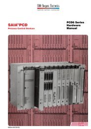
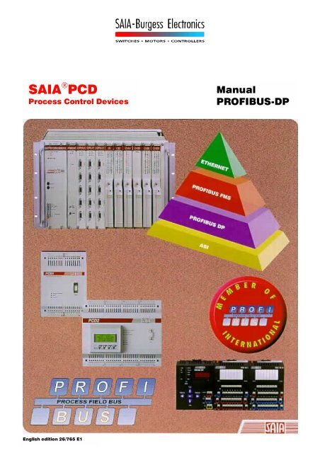
<strong>SAIA</strong> ® <strong>PCD</strong><br />
Process Control Devices<br />
Manual<br />
PROFIBUS-DP<br />
English edition 26/765 E1
<strong>SAIA</strong>-Burgess Electronics Ltd.<br />
Bahnhofstrasse 18<br />
CH-3280 Murten (Switzerland)<br />
http;//www.saia-burgess.com<br />
BA: Electronic Controllers Telephone 026 / 672 72 72<br />
Telefax 026 / 672 74 99<br />
___________________________________________________________________________________________________________________________<br />
<strong>SAIA</strong>-Burgess Companies<br />
Switzerland<br />
<strong>SAIA</strong>-Burgess Electronics AG<br />
Freiburgstrasse 33<br />
CH-3280 Murten<br />
026 672 77 77, Fax 026 670 19 83<br />
France<br />
<strong>SAIA</strong>-Burgess Electronics Sàrl.<br />
10, Bld. Louise Michel<br />
F-92230 Gennevilliers<br />
01 46 88 07 70, Fax 01 46 88 07 99<br />
Germany<br />
<strong>SAIA</strong>-Burgess Electronics GmbH<br />
Daimlerstrasse 1k<br />
D-63303 Dreieich<br />
06103 89 060, Fax 06103 89 06 66<br />
Nederlands<br />
<strong>SAIA</strong>-Burgess Electronics B.V.<br />
Hanzeweg 12c<br />
NL-2803 MC Gouda<br />
0182 54 31 54, Fax 0182 54 31 51<br />
Austria<br />
<strong>SAIA</strong>-Burgess Electronics Ges.m.b.H.<br />
Schallmooser Hauptstrasse 38<br />
A-5020 Salzburg<br />
0662 88 49 10, Fax 0662 88 49 10 11<br />
Belgium<br />
<strong>SAIA</strong>-Burgess Electronics Belgium<br />
Avenue Roi Albert 1er, 50<br />
B-1780 Wemmel<br />
02 456 06 20, Fax 02 460 50 44<br />
Italy<br />
<strong>SAIA</strong>-Burgess Electronics S.r.l.<br />
Via Cadamosto 3<br />
I-20094 Corsico MI<br />
02 48 69 21, Fax 02 48 60 06 92<br />
Hungary<br />
<strong>SAIA</strong>-Burgess Electronics Automation Kft.<br />
Liget utca 1.<br />
H-2040 Budaörs<br />
23 501 170, Fax 23 501 180<br />
Representatives<br />
Great Britain<br />
Canham Controls Ltd.<br />
25 Fenlake Business Centre, Fengate<br />
Peterborough PE1 5BQ UK<br />
01733 89 44 89, Fax 01733 89 44 88<br />
Portugal<br />
INFOCONTROL Electronica e Automatismo LDA.<br />
Praceta Cesário Verde, No 10 s/cv, Massamá<br />
P-2745 Queluz<br />
21 430 08 24, Fax 21 430 08 04<br />
Denmark<br />
Malthe Winje Automation AS<br />
Håndværkerbyen 57 B<br />
DK-2670 Greve<br />
70 20 52 01, Fax 70 20 52 02<br />
Spain<br />
Tecnosistemas Medioambientales, S.L.<br />
Poligono Industrial El Cabril, 9<br />
E-28864 Ajalvir, Madrid<br />
91 884 47 93, Fax 91 884 40 72<br />
Norway<br />
Malthe Winje Automasjon AS<br />
Haukelivn 48<br />
N-1415 Oppegård<br />
66 99 61 00, Fax 66 99 61 01<br />
Czech<br />
Republic<br />
ICS Industrie Control Service, s.r.o.<br />
Modranská 43<br />
CZ-14700 Praha 4<br />
2 44 06 22 79, Fax 2 44 46 08 57<br />
Sweden<br />
Malthe Winje Automation AB<br />
Truckvägen 14A<br />
S-194 52 Upplands Våsby<br />
08 795 59 10, Fax 08 795 59 20<br />
Poland<br />
SABUR Ltd.<br />
ul. Druzynowa 3A<br />
PL-02-590 Warszawa<br />
22 844 63 70, Fax 22 844 75 20<br />
Suomi/<br />
Finland<br />
ENERGEL OY<br />
Atomitie 1<br />
FIN-00370 Helsinki<br />
09 586 2066, Fax 09 586 2046<br />
Australia<br />
Siemens Building Technologies Pty. Ltd.<br />
Landis & Staefa Division<br />
411 Ferntree Gully Road<br />
AUS-Mount Waverley, 3149 Victoria<br />
3 9544 2322, Fax 3 9543 8106<br />
Argentina<br />
MURTEN S.r.l.<br />
Av. del Libertador 184, 4° “A”<br />
RA-1001 Buenos Aires<br />
054 11 4312 0172, Fax 054 11 4312 0172<br />
After sales service<br />
USA<br />
<strong>SAIA</strong>-Burgess Electronics Inc.<br />
1335 Barclay Boulevard<br />
Buffalo Grove, IL 60089, USA<br />
847 215 96 00, Fax 847 215 96 06<br />
___________________________________________________________________________________________________________________________<br />
Issue : 22.11.2000<br />
Subjet to change without notice
<strong>SAIA</strong> ® Process Control Devices<br />
Manual<br />
PROFIBUS-DP<br />
with <strong>SAIA</strong> ® <strong>PCD</strong><br />
<strong>SAIA</strong>-Burgess Electronics Ltd. 1999. All rights reserved<br />
Edition 26/765 E1 - 03.1999<br />
Subject to technical changes<br />
© <strong>SAIA</strong>-Burgess Electronics Ltd.
Updates<br />
Manual :<br />
PROFIBUS-DP with <strong>SAIA</strong> ® <strong>PCD</strong> - Edition E1<br />
Date Chapter Page Description<br />
02.2001 7.3 7-10 XOB EXOB<br />
<strong>SAIA</strong>-Burgess Controls Ltd.
PROFIBUS-DP<br />
Concerning this manual<br />
Concerning this manual<br />
The concept and practical application of PROFIBUS-DP is described in<br />
detail and complemented with the addition of various examples.<br />
If PROFIBUS is new territory for you, it is advisable to study the whole<br />
manual.<br />
If you already have some experience with PROFIBUS-FMS, you are advised<br />
to study the following chapters:<br />
2. <strong>SAIA</strong> ® <strong>PCD</strong> devices for the PROFIBUS-DP network<br />
4. The PROFIBUS-DP configurator<br />
5. Programming<br />
6. Commissioning a PROFIBUS-DP network<br />
If you are already familiar with PROFIBUS-DP, we recommend that you<br />
study the following chapters:<br />
2. <strong>SAIA</strong> ® <strong>PCD</strong> devices for the PROFIBUS-DP network<br />
4. The PROFIBUS-DP configurator<br />
5. Programming<br />
If you wish to have a quick summary of the use of <strong>SAIA</strong> devices with<br />
PROFIBUS-DP, we recommend that you study Chapter 7:<br />
7. Quick guide to creating a PROFIBUS-DP network<br />
26/765 E1 (PDP-V-E.DOC) © <strong>SAIA</strong>-Burgess Electronics Ltd. Page V-1
Concerning this manual<br />
PROFIBUS-DP<br />
Notes<br />
Page V-2 © <strong>SAIA</strong>-Burgess Electronics Ltd. (PDP-V-E.DOC) 26/765 E1
PROFIBUS-DP<br />
Contents<br />
Contents<br />
Page<br />
1. Characteristics and fundamentals<br />
1.1 Characteristics 1-1<br />
1.2 Basic principles 1-4<br />
1.2.1 ISO/OSI reference model 1-4<br />
1.2.2 PROFIBUS layer 1 (physical layer) 1-5<br />
1.2.3 PROFIBUS layer 2 (data link layer) 1-6<br />
1.2.4 PROFIBUS-DP 1-9<br />
2. <strong>SAIA</strong> ® <strong>PCD</strong> devices for the PROFIBUS-DP network<br />
2.1 PROFIBUS-DP master module 2-1<br />
2.2 PROFIBUS-DP slave module 2-4<br />
2.2.1 PROFIBUS-DP slave card <strong>PCD</strong>7.F77x 2-5<br />
2.2.2 PROFIBUS-DP RIO modules 2-8<br />
2.3 Connection of PROFIBUS-DP modules 2-9<br />
2.3.1 <strong>PCD</strong>7.F7xx card 2-9<br />
2.3.2 <strong>PCD</strong>0.Xxxx card 2-12<br />
2.3.3 Meaning of connections 2-12<br />
2.4 Ports 2 and 3 of <strong>PCD</strong>7.F77x slave modules 2-13<br />
2.4.1 Port 2 2-13<br />
2.4.2 Port 3 2-13<br />
2.5 Repeater <strong>PCD</strong>7.T100 2-14<br />
2.6 Termination box <strong>PCD</strong>7.T160 2-15<br />
26/765 E1 (PDP-00-E.DOC) © <strong>SAIA</strong>-Burgess Electronics Ltd. Page 1
Contents<br />
PROFIBUS-DP<br />
Page<br />
3. Planning and installation of a<br />
PROFIBUS-DP network<br />
3.1 Planning and installation of the physical layer 3-2<br />
3.1.1 Line parameters 3-3<br />
3.1.2 Connection of network stations 3-3<br />
3.1.3 Stub cables 3-6<br />
3.1.4 Network layout 3-7<br />
3.2 Logical network structure 3-10<br />
3.2.1 Definition of bus parameters 3-10<br />
3.2.2 Configuration of slaves 3-10<br />
3.2.3 Checking and assessing the performance<br />
values required 3-10<br />
4. The PROFIBUS-DP configurator<br />
4.1 General 4-2<br />
4.2 Procedure for PROFIBUS-DP configuration 4-4<br />
4.3 Description of PROFIBUS-DP configuration menu 4-5<br />
4.3.1 Main screen 4-5<br />
4.3.2 'Network' submenu 4-7<br />
4.3.3 'Edit' submenu 4-9<br />
4.3.4 'View' submenu 4-30<br />
4.3.5 'Library' submenu 4-31<br />
4.3.6 'Project' submenu 4-33<br />
4.3.7 'Window' submenu 4-34<br />
4.3.8 'Help' submenu 4-35<br />
4.3.9 Mouse-sensitive elements in configurator 4-36<br />
Page 2 © <strong>SAIA</strong>-Burgess Electronics Ltd. (PDP-00-E.DOC) 26/765 E1
PROFIBUS-DP<br />
Contents<br />
Page<br />
5. Programming<br />
5.1 Access to slave I/Os and registers in a<br />
<strong>PCD</strong> user program with PROFIBUS-DP 5-1<br />
5.2 Description of <strong>PCD</strong> instructions (SASI, SCON) 5-5<br />
5.2.1 SASI: Assigning a channel 5-6<br />
5.2.2 SCON instructions to affect data exchange 5-15<br />
5.2.3 SCONI instructions to affect data exchange 5-16<br />
5.2.4 History list messages 5-31<br />
5.2.5 Employing PG3 user programs in<br />
PROFIBUS-DP projects 5-32<br />
5.3 Rules for writing the user program 5-33<br />
5.4 Structure of the user program 5-34<br />
5.4.1 Cold-start program in XOB 16 5-34<br />
5.4.2 Main program in COB 5-34<br />
5.5 Program examples 5-37<br />
5.5.1 Example 1 5-37<br />
5.5.2 Example 2 5-38<br />
5.5.3 Example 3 5-77<br />
6. Commissioning a PROFIBUS-DP network<br />
6.1 Checking and testing the hardware installation<br />
(physical layer) 6-1<br />
6.2 Checking and testing data exchange 6-2<br />
6.2.1 Checking data exchange 6-2<br />
6.2.2 Checking the mapped media 6-3<br />
6.2.3 Use of bus monitors 6-4<br />
26/765 E1 (PDP-00-E.DOC) © <strong>SAIA</strong>-Burgess Electronics Ltd. Page 3
Contents<br />
PROFIBUS-DP<br />
Page<br />
7. Quick guide to create a PROFIBUS-DP network<br />
7.1 Electrical connection 7-2<br />
7.1.1 Connection of supply 7-2<br />
7.1.2 RS 485 connection 7-3<br />
7.1.3 Setting the PROFIBUS-DP address 7-4<br />
7.2 Configuration with the PROFIBUS-DP configurator 7-5<br />
7.3 Writing user programs 7-10<br />
7.3.1 User program in the master 7-10<br />
7.3.2 User program in Slave_2 7-11<br />
7.4 Commissioning user programs 7-12<br />
Appendix A:<br />
Appendix B:<br />
Appendix C:<br />
Machine state diagram of a PROFIBUS-DP slave<br />
CPU load and reaction time when using<br />
PROFIBUS-DP<br />
Tested Non-<strong>SAIA</strong> PROFIBUS-DP devices<br />
Page 4 © <strong>SAIA</strong>-Burgess Electronics Ltd. (PDP-00-E.DOC) 26/765 E1
PROFIBUS-DP<br />
Contents<br />
Please note:<br />
A number of detailed manuals are available to aid installation and operation<br />
of the <strong>SAIA</strong> <strong>PCD</strong>. These are for use by technically qualified staff,<br />
who may also have successfully completed one of our "workshops".<br />
To obtain the best performance from your <strong>SAIA</strong> <strong>PCD</strong>, closely follow the<br />
guidelines for assembly, wiring, programming and commissioning given<br />
in these manuals. In this way, you will also become one of the many enthusiastic<br />
<strong>SAIA</strong> <strong>PCD</strong> users.<br />
If you have any technical suggestions or recommendations for improvements<br />
to the manuals, please let us know. A form is provided on the last<br />
page of this manual for your comments.<br />
Summary<br />
<strong>PCD</strong>1/2 series <strong>PCD</strong>4 series <strong>PCD</strong>6 series<br />
Hardware<br />
<strong>PCD</strong>1<br />
<strong>PCD</strong>2<br />
Serie xx7<br />
<strong>PCD</strong>2.M220<br />
<strong>PCD</strong>2.H...<br />
Hardware<br />
<strong>PCD</strong>4<br />
<strong>PCD</strong>4.H1..<br />
<strong>PCD</strong>4.H2..<br />
*)<br />
*)<br />
Hardware<br />
<strong>PCD</strong>6<br />
General<br />
Manuals<br />
<strong>PCD</strong>4.H3..<br />
<strong>PCD</strong>4.H4..<br />
*)<br />
*) Adapter module 4'717'4828'0<br />
allows H modules to be used<br />
with the <strong>PCD</strong>6.<br />
User's<br />
Guide<br />
Reference<br />
Guide<br />
(P G3 )<br />
<strong>PCD</strong>8.P1..<br />
<strong>PCD</strong>7.D1..<br />
PCA2.D1..<br />
<strong>PCD</strong>7.D2..<br />
- S-Bus<br />
- PROFIBUS-FMS<br />
- PROFIBUS-DP<br />
Installation<br />
Components<br />
for RS 485-<br />
Networks<br />
- PG4<br />
- Modem<br />
FUPLA/<br />
KOPLA<br />
function<br />
families<br />
26/765 E1 (PDP-00-E.DOC) © <strong>SAIA</strong>-Burgess Electronics Ltd. Page 5
Contents<br />
PROFIBUS-DP<br />
Reliability and safety of electronic controllers<br />
<strong>SAIA</strong>-Burgess Electronics Ltd. is a company which devotes the greatest<br />
care to the design, development and manufacture of its products:<br />
• state-of-the-art technology<br />
• compliance with standards<br />
• ISO 9001 certification<br />
• international approvals: e.g. Germanischer Lloyd, UL,<br />
Det Norske Veritas, CE mark ...<br />
• choice of high-quality componentry<br />
• quality control checks at various stages of production<br />
• in-circuit tests<br />
• run-in (burn-in at 85°C for 48h)<br />
Despite every care, the excellent quality which results from this does<br />
have its limits. It is therefore necessary, for example, to reckon with the<br />
natural failure of components. For this reason <strong>SAIA</strong>-Burgess Electronics<br />
Ltd. provides a guarantee according to the "General terms and conditions<br />
of supply".<br />
The plant engineer must in turn also contribute his share to the reliable<br />
operation of an installation. He is therefore responsible for ensuring that<br />
controller use conforms to the technical data and that no excessive<br />
stresses are placed on it, e.g. with regard to temperature ranges, overvoltages<br />
and noise fields or mechanical stresses.<br />
In addition, the plant engineer is also responsible for ensuring that a<br />
faulty product in no case leads to personal injury or even death, nor to<br />
the damage or destruction of property. The relevant safety regulations<br />
should always be observed. Dangerous faults must be recognized by additional<br />
measures and any consequences prevented. For example, outputs<br />
which are important for safety should lead back to inputs and be monitored<br />
from software. Consistent use should be made of the diagnostic<br />
elements of the <strong>PCD</strong>, such as the watchdog, exception organization<br />
blocks (XOB) and test or diagnostic instructions.<br />
If all these points are taken into consideration, the <strong>SAIA</strong> <strong>PCD</strong> will provide<br />
you with a modern, safe programmable controller to control, regulate<br />
and monitor your installation with reliability for many years.<br />
Page 6 © <strong>SAIA</strong>-Burgess Electronics Ltd. (PDP-00-E.DOC) 26/765 E1
PROFIBUS-DP<br />
Characteristics and fundamentals<br />
1. Characteristics and fundamentals<br />
PROFIBUS (PROcess FIeld BUS) is the successful, open, industrial<br />
fieldbus standard for a broad application spectrum.<br />
1.1 Characteristics<br />
• Open<br />
PROFIBUS enables the exchange of data between devices from different<br />
manufacturers, without special interface adjustments. PROFIBUS has<br />
been standardized under German standard DIN 19 245 and European<br />
standard pr EN 50170.<br />
• Vendor independent<br />
PROFIBUS devices are offered by many qualified manufacturers. This<br />
enables the user to select the most suitable device from a preferred<br />
manufacturer for whichever application.<br />
• Optimized for a wide field of use<br />
PROFIBUS comprises the following three application-specific versions:<br />
Figure 1: Overview of PROFIBUS versions<br />
26/765 E1 (PDP-10-E.DOC) © <strong>SAIA</strong>-Burgess Electronics Ltd. Page 1-1
Characteristics and fundamentals<br />
PROFIBUS-DP<br />
PROFIBUS has been standardized under European standard EN 50170<br />
and the earlier German standard DIN 19245 parts 1 - 4.<br />
PROFIBUS-FMS<br />
(FMS = Fieldbus Message Specification)<br />
This is the general-purpose solution for communications tasks at the field<br />
and cell levels of the industrial communications hierarchy. Powerful FMS<br />
services open up a wide range of applications, provide great flexibility<br />
and enable comprehensive communication tasks to be managed with<br />
cyclic or acyclic data communication at medium speed.<br />
PROFIBUS-DP<br />
(DP = Decentralized Peripherals)<br />
Optimized for high speed, this PROFIBUS version has been especially<br />
tailored for communication between automation systems and local<br />
peripherals, enabling plug-and-play for field devices.<br />
PROFIBUS-FMS and DP use the same transmission technology and the<br />
same bus access protocol. Both versions can therefore run simultaneously<br />
and in combination on a single cable.<br />
PROFIBUS-PA<br />
(PA = Process Automation)<br />
PROFIBUS-PA is the PROFIBUS version for process automation<br />
applications. PROFIBUS-PA uses the intrinsically safe transmission<br />
technology defined in IEC 1158-2 and enables the remote supply of<br />
stations through the bus.<br />
The protocol functions of PROFIBUS-FMS, DP and PA are<br />
complemented by profiles which describe how PROFIBUS is used in<br />
special fields of application, such as process automation, building control<br />
technology or automated manufacturing.<br />
Device profiles define device-specific functions. The device description<br />
language (DDL) and function blocks ensure that devices are fully<br />
interoperable.<br />
Page 1-2 © <strong>SAIA</strong>-Burgess Electronics Ltd. (PDP-10.E.DOC) 26/765 E1
PROFIBUS-DP<br />
Characteristics and fundamentals<br />
Transparent Communication from<br />
Sensor/Actuator up to Area<br />
Figure 2: Communication in the field area<br />
• Proven<br />
PROFIBUS is a complete, proven technology which has already stood the<br />
test of more than 100 000 applications in the fields of building<br />
automation, automated production, process automation and drive<br />
technology.<br />
• Certificated<br />
Tests of conformity and interoperability performed in laboratories<br />
authorized by the PROFIBUS user organization (PNO), combined with<br />
PNO device certification, give the user an assurance of guaranteed<br />
quality and functionality, even in multi-vendor installations.<br />
26/765 E1 (PDP-10-E.DOC) © <strong>SAIA</strong>-Burgess Electronics Ltd. Page 1-3
Characteristics and fundamentals<br />
PROFIBUS-DP<br />
1.2 Basic principles<br />
To construct a PROFIBUS network and exchange data across it, you must<br />
now read and understand the following chapters in full. If you plan<br />
PROFIBUS communication with <strong>SAIA</strong> ® <strong>PCD</strong> devices only, this in itself is<br />
a very simple undertaking and you can continue directly with chapter 2.<br />
However, if you would also like to improve your knowledge and<br />
understanding of PROFIBUS theory, you will certainly find the following<br />
chapter useful.<br />
1.2.1 ISO/OSI reference model<br />
Figure 3: ISO/OSI reference model<br />
Page 1-4 © <strong>SAIA</strong>-Burgess Electronics Ltd. (PDP-10.E.DOC) 26/765 E1
PROFIBUS-DP<br />
Characteristics and fundamentals<br />
1.2.2 PROFIBUS layer 1 (physical layer)<br />
PROFIBUS protocol architecture follows the ISO / OSI (open system<br />
interconnection) reference model, in line with international standard ISO<br />
7498.<br />
In this model each layer takes on precisely defined tasks. Layer 1<br />
(physical layer) defines the physical transmission technology. Layer 2<br />
(data link layer) defines the bus access procedure. Layer 7 (application<br />
layer) defines the user level.<br />
A fieldbus system’s field of use is essentially determined by the choice of<br />
transmission medium and the physical bus interface. Apart from the<br />
requirements of transmission security, expenditure on purchasing and<br />
installing the bus cable is crucially important. The PROFIBUS standard<br />
therefore provides for various forms of transmission technology, while<br />
retaining a uniform bus protocol.<br />
Cable-bound transmission: This version complies with US standard EIA<br />
RS-485 and was defined as the basic version for applications in the field<br />
of production engineering, building control technology and drive<br />
technology. It uses screened, twisted copper cable with a pair of<br />
conductors.<br />
Fibre-optic cable: For applications in very interference-prone<br />
environments, and to extend working range at high transmission speeds,<br />
the PNO has worked out a specification for fibre-optic based<br />
transmission technology.<br />
Intrinsically safe transmission: PROFIBUS-PA enables the intrinsically<br />
safe transmission and supply of stations across the bus. The transmission<br />
technology is described in international standard IEC 1158-2.<br />
26/765 E1 (PDP-10-E.DOC) © <strong>SAIA</strong>-Burgess Electronics Ltd. Page 1-5
Characteristics and fundamentals<br />
PROFIBUS-DP<br />
1.2.3 PROFIBUS layer 2 (data link layer)<br />
The second layer of the OSI reference model realizes the functions of bus<br />
access control, data protection and the transaction of transmission<br />
protocols and telegrams. In PROFIBUS, layer 2 is called the fieldbus data<br />
link (FDL).<br />
Bus access control (MAC, Medium Access Control) defines the<br />
procedure for when a station on the bus can transmit data. The MAC<br />
must ensure that, at any one time, only one station ever has authorization<br />
to transmit.<br />
The PROFIBUS bus access method therefore includes a token-passing<br />
procedure for communication between complex stations (masters) and an<br />
underlying master-slave procedure for the communication of complex<br />
stations with low-expense peripheral devices (slaves). This combined<br />
procedure is called a hybrid bus access procedure (see figure 3).<br />
In PROFIBUS, the token-passing procedure only applies between<br />
complex stations (masters).<br />
The master-slave procedure allows the master (active station) currently<br />
holding transmission authorization to speak to its assigned slave devices<br />
(passive stations). This gives the master the opportunity of transmitting<br />
messages to the slaves or uploading messages from them.<br />
With this hybrid access method for PROFIBUS, the following system<br />
configurations can be realized:<br />
• Straight master-slave system.<br />
• Straight master-master system (token passing).<br />
• A system combining both methods.<br />
Figure 3 shows a PROFIBUS structure with three active stations<br />
(masters) and seven passive stations (slaves). The three master devices<br />
form a logical token ring.<br />
If an active station receives the token telegram, it can exercise for a<br />
certain time the function of master across the bus, communicating with<br />
all slave stations in a master-slave relationship and with all master<br />
stations in a master-master relationship.<br />
Page 1-6 © <strong>SAIA</strong>-Burgess Electronics Ltd. (PDP-10.E.DOC) 26/765 E1
PROFIBUS-DP<br />
Characteristics and fundamentals<br />
Figure 4:<br />
Hybrid bus access method<br />
The term: "token ring" refers to the organizational stringing together of<br />
active stations which, by their bus addresses, form a logical ring. In this<br />
ring the token (bus access authorization) is passed from one master to the<br />
next in a predefined order (ascending addresses).<br />
The task of the bus access controller (MAC) for active stations is to<br />
recognize this logical assignment in the bus system’s "run-up phase" and<br />
establish the token ring. While operating in "run", any (active) station<br />
which is faulty or switched off is disconnected from the ring and any<br />
newly added active station is connected to it. These performance<br />
characteristics, together with the recognition of faults in the transmission<br />
medium, line receiver and errors of station addressing (e.g. multiple<br />
occupation) or token passing (e.g. multiple tokens or token loss), are<br />
typical features of PROFIBUS access control.<br />
Another important task of layer 2 is data protection. The PROFIBUS<br />
layer 2 telegram formats enable great transmission security. All telegrams<br />
have a hamming distance of HD = 4. This is achieved by application of<br />
the rules under international standard IEC 870-5-1, selecting special start<br />
and end characters for telegrams, slip-resistant synchronization, parity<br />
bits and control bytes.<br />
26/765 E1 (PDP-10-E.DOC) © <strong>SAIA</strong>-Burgess Electronics Ltd. Page 1-7
Characteristics and fundamentals<br />
PROFIBUS-DP<br />
PROFIBUS-FMS and PROFIBUS-DP both use their own specific subset<br />
of layer 2 services (see table below). Services are called from higherranking<br />
levels via the service access points (SAPs) of level 2. With<br />
PROFIBUS-FMS these service access points are used for addressing the<br />
logical communication relationships. With PROFIBUS-DP a precisely<br />
defined function is assigned to each service access point used. For all<br />
active and passive stations, several service access points can be used in<br />
parallel. A difference is drawn between source (SSAP) and receiving<br />
service access points (RSAP).<br />
Table: Services of the PROFIBUS data protection layer (layer 2).<br />
Servic Function Used with<br />
e<br />
SDA Send Data with Acknowledge FMS<br />
SRD Send And Request Data With Reply FMS DP<br />
SDN Send Data With No Acknowledge FMS DP<br />
CSRD Cyclic Send And Request Data With<br />
Reply<br />
FMS<br />
The following SAPs are occupied by PROFIBUS-DP and cannot be used<br />
for FMS in a mixed FMS- DP network:<br />
Function SSAP DSAP Service<br />
Data_Exchange Default Default SRD<br />
Chk_Cfg 62 62 SRD<br />
Set_Prm 62 61 SRD<br />
Slave_Diag 62 60 SRD<br />
Get_Cfg 62 59 SRD<br />
Global_Control 62 58 SDN<br />
RD_Outp 62 57 SRD<br />
RD_Inp 62 56 SRD<br />
Set_Slave_Add 62 55 SRD<br />
reserved 54<br />
reserved 53<br />
reserved 52<br />
reserved 51<br />
Page 1-8 © <strong>SAIA</strong>-Burgess Electronics Ltd. (PDP-10.E.DOC) 26/765 E1
PROFIBUS-DP<br />
Characteristics and fundamentals<br />
1.2.4 PROFIBUS-DP<br />
• PROFIBUS layer 7 (application layer)<br />
Layer 7 of the ISO/OSI reference model is not used in PROFIBUS-DP.<br />
• PROFIBUS DP characteristics<br />
• Replaces costly parallel cabling between PLC/PC and I/Os<br />
• Fast: transmits 1 kByte input and output data in less than 2ms<br />
• Powerful tools reduce engineering costs<br />
• Supported by all main PLC manufacturers<br />
• Great diversity of products available, e.g. PLCs/PCs, I/Os, drives,<br />
valves, encoders<br />
• Cyclic and acyclic data transmission possible<br />
• Monomaster and multimaster networks can be created<br />
• Up to 246 Bytes of input and output data possible per station<br />
26/765 E1 (PDP-10-E.DOC) © <strong>SAIA</strong>-Burgess Electronics Ltd. Page 1-9
Characteristics and fundamentals<br />
PROFIBUS-DP<br />
• PROFIBUS DP device types<br />
PROFIBUS-DP defines three device types:<br />
• DP master class 1 (DPM1)<br />
Central control which exchanges data<br />
with the local I/Os (DP slaves).<br />
Several DPM1s are allowed, typical<br />
devices are PLCs, PCs, VMEs<br />
• DP master class 2 (DPM2)<br />
Project planning, monitoring or<br />
engineering tool which is used for<br />
commissioning or parameter setting/<br />
monitoring of DP slaves.<br />
• DP slave<br />
Local device with direct interface to<br />
input / output signals.<br />
Typical devices are I/Os, drives,<br />
valves, control units...<br />
Page 1-10 © <strong>SAIA</strong>-Burgess Electronics Ltd. (PDP-10.E.DOC) 26/765 E1
PROFIBUS-DP<br />
Characteristics and fundamentals<br />
• PROFIBUS DP systems<br />
PROFIBUS-DP can operate either as a monomaster or multimaster<br />
system:<br />
• Monomaster System<br />
Figure 5:<br />
PROFIBUS-DP monomaster system<br />
PROFIBUS-DP usually works as a monomaster system. This means that a<br />
master device, e.g. a PLC, is networked via PROFIBUS-DP with<br />
distributed peripheral devices, e.g. inputs and outputs. PROFIBUS-DP<br />
replaces the parallel cabling between the PLC and local peripherals.<br />
A PROFIBUS-DP monomaster system consists of between 1 and 125<br />
slaves, a class 1 master (i.e. the PLC) and an optional class 2 master (i.e.<br />
a configurator).<br />
Monomaster systems achieve the shortest bus cycle times; they transmit<br />
1 kByte of input and output data in less than 2 ms.<br />
26/765 E1 (PDP-10-E.DOC) © <strong>SAIA</strong>-Burgess Electronics Ltd. Page 1-11
Characteristics and fundamentals<br />
PROFIBUS-DP<br />
• Multimaster System<br />
Figure 6:<br />
PROFIBUS-DP multimaster system<br />
PROFIBUS-DP can also be used in a multimaster configuration.<br />
Figure 6 shows two active devices, a PLC and a CNC. Each station has<br />
assigned input and output devices.<br />
The advantage of PROFIBUS-DP is that active devices can access the<br />
data of devices assigned as common.<br />
The DP class 2 master has the possibility of reading the diagnostic data of<br />
all devices on the bus.<br />
Page 1-12 © <strong>SAIA</strong>-Burgess Electronics Ltd. (PDP-10.E.DOC) 26/765 E1
PROFIBUS-DP<br />
Characteristics and fundamentals<br />
• PROFIBUS DP communication functions<br />
PROFIBUS-DP communication functions are differentiated according to<br />
the following relationships:<br />
• Class 1 master and DP slaves<br />
• Class 2 master and DP slaves<br />
• Class 2 master and class 1 master<br />
Possible communication relationships:<br />
Function DPM1<br />
DP slaves<br />
DPM2<br />
DP slaves<br />
DPM1<br />
DPM2<br />
Parameter setting/configuration • • ⎯<br />
Transmission of slave diagnostic • • ⎯<br />
data<br />
Transmission of master<br />
⎯ ⎯ •<br />
diagnostic data<br />
Cyclic data communications • • ⎯<br />
Sync + freeze commands • • ⎯<br />
Set slave address ⎯ • ⎯<br />
Acyclic read of input/output ⎯ • ⎯<br />
images<br />
Acyclic read/write of data • (X) • (X) ⎯<br />
Alarm handling functions • (X) • (X) ⎯<br />
Upload/download of master<br />
parameter records<br />
⎯ ⎯ •<br />
(X)<br />
These expanded PROFIBUS-DP functions are specified in technical instruction no.<br />
2.082.<br />
PROFIBUS-DP does not <strong>support</strong> communication between several<br />
DPM1s. If this functionality is required, PROFIBUS-FMS should be used<br />
in addition.<br />
The expanded DP functions are mainly used for intelligent slaves with<br />
many different parameters which have to be modified during operation.<br />
The new read and write functions were defined for this purpose.<br />
It is important that the expanded DP protocol is upwardly compatible with<br />
basic DP functions. This means that devices on which the new functions<br />
have been implemented are fully interoperable with devices lacking this<br />
expanded functionality. The only restriction is that devices which lack the<br />
expanded functions cannot execute the new functions.<br />
26/765 E1 (PDP-10-E.DOC) © <strong>SAIA</strong>-Burgess Electronics Ltd. Page 1-13
Characteristics and fundamentals<br />
PROFIBUS-DP<br />
• PROFIBUS DP data transmission<br />
Data transmission with PROFIBUS-DP is based on a highly efficient<br />
telegram structure.<br />
Figure 7:<br />
Principle of useful data communication with PROFIBUS-<br />
DP<br />
The input and output data of a device are transferred in a single bus<br />
cycle. The master sends a calling telegram which contains output data for<br />
the DP slave. In its reply telegram, the DP slave transmits its input data to<br />
the master. After receipt of the calling telegram, the DP slave answers<br />
directly. Each telegram can transmit up to 244 Bytes of input or output<br />
data.<br />
If the calling or reply telegrams have been corrupted by electromagnetic<br />
interference, the master immediately repeats the message cycle. The<br />
number of repetitions can be configured.<br />
All PROFIBUS telegrams have high transmission security with a<br />
hamming distance of HD=4. The hamming distance is a measure of a<br />
system’s error protection. This means that the higher the hamming<br />
distance, the better the system security. HD=4 meets the requirements for<br />
security-related applications.<br />
Page 1-14 © <strong>SAIA</strong>-Burgess Electronics Ltd. (PDP-10.E.DOC) 26/765 E1
PROFIBUS-DP<br />
Characteristics and fundamentals<br />
• PROFIBUS DP bus cycle time<br />
The bus cycle time of a PROFIBUS-DP system depends mainly on the<br />
baud rate used. The baud rate is selectable between 9.6 kBit and 12<br />
MBit, in steps.<br />
Figure 8:<br />
Bus cycle time of a PROFIBUS-DP monomaster system<br />
Example for figure 8:<br />
In a system configuration of 30 DP slaves working at 12 MBit and in<br />
which each slave has 2 Bytes of input and output data, a bus cycle time<br />
of approx. 1 ms is achieved.<br />
This shows that PROFIBUS-DP can be used even in very time-critical<br />
applications.<br />
26/765 E1 (PDP-10-E.DOC) © <strong>SAIA</strong>-Burgess Electronics Ltd. Page 1-15
Characteristics and fundamentals<br />
PROFIBUS-DP<br />
• Project planning with PROFIBUS DP bus cycle time<br />
PROFIBUS not only describes the communication of devices with each<br />
other; it also provides a framework for open, vendor-independent project<br />
planning.<br />
Figure 9:<br />
Project planning with PROFIBUS-DP<br />
Project planning tools, e.g. SNET, use electronic data sheets for the<br />
devices. These electronic data sheets are called device database files or<br />
GSD files (GSD = Geräte-Stamm-Daten). These files are usually supplied<br />
on a diskette with the device. For many PROFIBUS devices, these files<br />
can also be uploaded from the PROFIBUS homepage<br />
http://www.profibus.com/.<br />
Manufacturers describe the functionality of their devices with the help of<br />
a GSD file. The format of GSD files has a fixed definition within the<br />
PROFIBUS standard. The project planning tool reads the GSD file into its<br />
internal database and takes into consideration all the characteristics of<br />
the device in question.<br />
This simplifies project planning and can be carried out with a vendorindependent<br />
project planning tool. PROFIBUS-DP therefore permits<br />
genuine plug-and-play solutions and reduces engineering costs.<br />
Page 1-16 © <strong>SAIA</strong>-Burgess Electronics Ltd. (PDP-10.E.DOC) 26/765 E1
PROFIBUS-DP<br />
<strong>SAIA</strong> ® <strong>PCD</strong> devices for the PROFIBUS-DP network<br />
2. <strong>SAIA</strong> ® <strong>PCD</strong> devices for the<br />
PROFIBUS-DP network<br />
2.1 PROFIBUS-DP master module<br />
2.1.1 PROFIBUS-DP master card <strong>PCD</strong>7.F750<br />
Figure 1: View of <strong>PCD</strong>7.F750<br />
<strong>PCD</strong> CPU<br />
<strong>PCD</strong> Databus<br />
Dual port<br />
RAM<br />
RAM<br />
Flash<br />
LED<br />
RUN<br />
µC - Bus<br />
ERROR<br />
Quartz<br />
µC<br />
C165<br />
Bootstrap<br />
loader<br />
port<br />
Siemens<br />
ASPC2<br />
galvanic isolation<br />
RS 485<br />
Opto Driver<br />
RxD/TxD-P<br />
RxD/TxD-N<br />
RTS<br />
<strong>PCD</strong>7.F750<br />
DC S+5V<br />
+5V<br />
SGN<br />
DC<br />
PTC DP+5<br />
DPGN<br />
PGN<br />
Figure 2: Block diagram <strong>PCD</strong>7.F750<br />
26/765 E1 (PDP-20.E.DOC) © <strong>SAIA</strong>-Burgess Electronics Ltd. Page 2-1
<strong>SAIA</strong> ® <strong>PCD</strong> devices for the PROFIBUS-DP network<br />
PROFIBUS-DP<br />
Technical data <strong>PCD</strong>7.F750<br />
Function<br />
Profibus-DP master class 1 E (DPM1 with extension)<br />
Maximum number of stations 32 per segment / max. 126 per system (with repeaters)<br />
Profibus ASIC<br />
ASPC2<br />
Baud rate (kbit/s) 9.6 -12000<br />
Internal current consumption max. 400 mA<br />
from 5V bus<br />
Current output DP+5V max. 50 mA short-circuit proof with PTC<br />
Galvanic isolation<br />
between <strong>PCD</strong>-GND and PROFIBUS connection GND<br />
Functions <strong>support</strong>ed<br />
Function<br />
Data_Exchange<br />
Slave_Diag<br />
Set_Prm<br />
Chk_Cfg<br />
Global Control<br />
Get_Master_Diag<br />
Profibus-DP master class 1 E (DPM1 with extension)<br />
Request<br />
Response<br />
X<br />
X<br />
X<br />
X<br />
X<br />
X<br />
Hardware and firmware versions <strong>support</strong>ing the <strong>PCD</strong>7.F750<br />
PROFIBUS-DP master module<br />
<strong>PCD</strong> System HW FW<br />
<strong>PCD</strong><br />
1/2/6<br />
FW<br />
<strong>PCD</strong>7.<br />
F750<br />
Max. E/A<br />
Memory for DP<br />
**)<br />
PG/Configurator<br />
Vers. Modif. Vers. Vers. Bytes Vers.<br />
C 3<br />
<strong>PCD</strong>1.M120/M130<br />
006 001 2942 PG4 2.0<br />
D -<br />
J *) 7<br />
<strong>PCD</strong>2.M120/M220<br />
007 001 2942 PG4 2.0<br />
K -<br />
A 234<br />
<strong>PCD</strong>6.M300 B 34 002 001 2942 PG4 2.0<br />
C -<br />
<strong>PCD</strong>1.M137 A - 1.300 001 1024 E + 1024 A STEP7 3.0<br />
<strong>PCD</strong>2.M127 H - 1.300 001 1024 E + 1024 A STEP7 3.0<br />
<strong>PCD</strong>2.M227 H*) - 1.300 001 1024 E + 1024 A STEP7 3.0<br />
*) <strong>PCD</strong>2.M22x Version of board <strong>PCD</strong>2.M12x<br />
**) I/O memory for DP:<br />
This is the maximum number of bytes that can be used for I/O data<br />
exchange between the master and all slaves (number is checked in<br />
the configurator)<br />
Example for <strong>PCD</strong>2.M120:<br />
- 100 slaves with 29 bytes, or<br />
- 12 slaves with 244 bytes.<br />
Page 2-2 © <strong>SAIA</strong>-Burgess Electronics Ltd. (PDP-20.E.DOC) 26/765 E1
PROFIBUS-DP<br />
<strong>SAIA</strong> ® <strong>PCD</strong> devices for the PROFIBUS-DP network<br />
Meaning of LEDs<br />
The <strong>PCD</strong>7.F750 card is equipped with a Run LED and an Error LED.<br />
The LEDs on the <strong>PCD</strong>7.F750 card are switched in the following way:<br />
Function <strong>PCD</strong>7.F750 Run LED <strong>PCD</strong>7.F750 Error LED<br />
Power-up 1 sec. on 1 sec. on<br />
then flashing ~ 10Hz off<br />
DP SASI instruction flashing ~ 1Hz 0.1 sec. on<br />
then flashing ~ 1Hz –0.01Hz off<br />
Program running normally flashing ~ 1Hz –0.01Hz off<br />
Errors are indicated as follows:<br />
<strong>PCD</strong>7.F750 Run LED<br />
Flashing ~ 10Hz<br />
off<br />
Flashing ~ 1Hz<br />
<strong>PCD</strong>7.F750 Error LED<br />
off<br />
On<br />
Flashing ~ 1Hz<br />
Possible causes of errors are:<br />
• <strong>PCD</strong>7.F750 firmware does not match the FW of the <strong>PCD</strong>1/2/6.<br />
• Wiring is not OK.<br />
(Bad cable, wires transposed, no termination)<br />
• Too many I/O bytes used.<br />
• Wrong configuration<br />
Errors are stored in the <strong>PCD</strong>’s history log.<br />
To discover the precise cause of an error, the history log must be<br />
displayed.<br />
26/765 E1 (PDP-20.E.DOC) © <strong>SAIA</strong>-Burgess Electronics Ltd. Page 2-3
<strong>SAIA</strong> ® <strong>PCD</strong> devices for the PROFIBUS-DP network<br />
PROFIBUS-DP<br />
2.2 PROFIBUS-DP slave module<br />
The following PROFIBUS-DP slave modules are available:<br />
Module Function<br />
<strong>PCD</strong>7.F770 DP slave module for <strong>PCD</strong>1 / 2 / 6.M300<br />
<strong>PCD</strong>7.F772 DP slave module for <strong>PCD</strong>2 with port 3, RS485<br />
<strong>PCD</strong>7.F774 *) DP slave module for <strong>PCD</strong>1 / 2<br />
with port 3, RS485 and connection for <strong>PCD</strong>7.D160<br />
terminal<br />
<strong>PCD</strong>0.T770 Profibus-DP RIO bus coupler<br />
<strong>PCD</strong>0.G110 Profibus-DP RIO with 8 I/O 24VDC<br />
<strong>PCD</strong>0.G120 Profibus-DP RIO with 16 I 24VDC<br />
<strong>PCD</strong>0.G130 Profibus-DP RIO with 16 O 24VDC<br />
*) Only available as <strong>PCD</strong>7.D164 terminal set.<br />
This set includes a plug-on ..D160 terminal with the additional RS 485<br />
communications ports (galvanically isolated) on Port 3 and PROFIBUS-<br />
DP slave interface.<br />
With the <strong>PCD</strong>1, Port 3 is not <strong>support</strong>ed and, for the terminal, the housing<br />
cover with a recess (order number 4 104 7338 0) must also be used.<br />
Page 2-4 © <strong>SAIA</strong>-Burgess Electronics Ltd. (PDP-20.E.DOC) 26/765 E1
PROFIBUS-DP<br />
<strong>SAIA</strong> ® <strong>PCD</strong> devices for the PROFIBUS-DP network<br />
2.2.1 PROFIBUS-DP slave card <strong>PCD</strong>7.F77x<br />
Figure 3: View of <strong>PCD</strong>7.F774<br />
<strong>PCD</strong> CPU<br />
<strong>PCD</strong> data and<br />
address bus<br />
Siemens<br />
SPC4.1<br />
galvanic isolation<br />
Opto RS 485<br />
driver<br />
RxD/TxD-<br />
RxD/TxD-<br />
Oscill.<br />
DC<br />
+5V S+5V<br />
SGND<br />
DC<br />
PTC<br />
RTS<br />
DP+5<br />
DPGN<br />
PGND<br />
<strong>PCD</strong>7.F774<br />
DUART<br />
Quartz<br />
Port 2 to display <strong>PCD</strong>7.D160<br />
Port 3<br />
Opto<br />
galvanic isolation<br />
RS 485<br />
driver<br />
/TxD-/RxD<br />
TxD-RxD<br />
Figure 4: Block diagram <strong>PCD</strong>7.F774<br />
26/765 E1 (PDP-20.E.DOC) © <strong>SAIA</strong>-Burgess Electronics Ltd. Page 2-5
<strong>SAIA</strong> ® <strong>PCD</strong> devices for the PROFIBUS-DP network<br />
PROFIBUS-DP<br />
Technical data <strong>PCD</strong>7.F770 / F772 / F774<br />
Function<br />
Profibus-DP slave E<br />
Maximum number of stations 32 per segment / max. 126 per system (with repeaters)<br />
Profibus ASIC<br />
SPC4.1<br />
Baud rate (kbit/s) 9.6-12000<br />
Internal current consumption from Max. 250 mA<br />
5V bus<br />
Current output DP+5V<br />
Max. 50 mA short circuit-proof with PTC<br />
Galvanic isolation<br />
between <strong>PCD</strong>-GND and PROFIBUS GND<br />
Port 2<br />
On <strong>PCD</strong>7.F774 for D160 display (TTL level)<br />
Port 3<br />
On <strong>PCD</strong>7.F772 and <strong>PCD</strong>7.F774,<br />
RS485 galvanically isolated from <strong>PCD</strong>-GND and<br />
PROFIBUS GND<br />
Functions <strong>support</strong>ed<br />
Function<br />
Data_Exchange<br />
RD_Inp<br />
RD_Outp<br />
Slave_Diag<br />
Set_Prm<br />
Chk_Cfg<br />
Get_Cfg<br />
Global Control<br />
Profibus-DP master class 1 E (DPM1 with extension)<br />
Request<br />
Response<br />
X<br />
X<br />
X<br />
X<br />
X<br />
X<br />
X<br />
X<br />
Hardware and firmware versions <strong>support</strong>ing the <strong>PCD</strong>7.F77x<br />
PROFIBUS-DP slave module<br />
<strong>PCD</strong> System HW FW<br />
<strong>PCD</strong><br />
1/2/6<br />
Max. E/A<br />
Memory for DP<br />
**)<br />
PG/Configurator<br />
Vers. Modif. Vers. Bytes Vers.<br />
C 3<br />
<strong>PCD</strong>1.M120/M130<br />
006 244 E + 244 A PG4 2.0<br />
D -<br />
J*) 7<br />
<strong>PCD</strong>2.M120/M220<br />
007 244 E + 244 A PG4 2.0<br />
K -<br />
A 234<br />
<strong>PCD</strong>6.M300 B 34 002 244 E + 244 A PG4 2.0<br />
C -<br />
<strong>PCD</strong>1.M137 A - 1.300 122 E + 122 A STEP7 3.0<br />
<strong>PCD</strong>2.M127 H - 1.300 122 E + 122 A STEP7 3.0<br />
<strong>PCD</strong>2.M227 H*) - 1.300 122 E + 122 A STEP7 3.0<br />
*) Version of board <strong>PCD</strong>2.M12x<br />
*) I/O memory for DP:<br />
This is the maximum number of bytes that can be used for the<br />
exchange of data between the master and slave. (Number is<br />
checked by the configurator.)<br />
This value is dependent upon:<br />
Total I/O data, number of modules, number of diagnostic bytes, etc.<br />
Page 2-6 © <strong>SAIA</strong>-Burgess Electronics Ltd. (PDP-20.E.DOC) 26/765 E1
PROFIBUS-DP<br />
<strong>SAIA</strong> ® <strong>PCD</strong> devices for the PROFIBUS-DP network<br />
Supported PROFIBUS-DP diagnostics of <strong>PCD</strong>7.F77x slave modules<br />
<strong>PCD</strong>7.F77x slave modules <strong>support</strong> the 6 bytes of standard PROFIBUS-<br />
DP diagnostics (Base+0 to Base+5)<br />
In addition, byte 7 (Base+6) of the expanded PROFIBUS-DP diagnostics<br />
is sent in the following cases:<br />
• CPU in STOP<br />
• CPU in HALT<br />
Here, byte 7 (Base+6) stores the following information:<br />
CPU Status Transmission of ASCII character in byte 7<br />
byte 7 (Base+6)<br />
RUN no No character<br />
STOP yes ‘S‘ (0053h)<br />
HALT yes ‘H‘ (0048h)<br />
GSD files for PROFIBUS-DP <strong>SAIA</strong> slaves<br />
Slave<br />
<strong>PCD</strong>0.T770<br />
<strong>PCD</strong>0.G110<br />
<strong>PCD</strong>0.G120<br />
<strong>PCD</strong>0.G130<br />
<strong>PCD</strong>1.M120<br />
<strong>PCD</strong>1.M120<br />
<strong>PCD</strong>2.M120<br />
<strong>PCD</strong>2.M220<br />
<strong>PCD</strong>6.M300<br />
GSD file<br />
Saia1631.gsd<br />
Saia1635.gsd<br />
Saia1634.gsd<br />
Saia1633.gsd<br />
Saiacd10.gsd<br />
Saiacd20.gsd<br />
Saiacd60.gsd<br />
26/765 E1 (PDP-20.E.DOC) © <strong>SAIA</strong>-Burgess Electronics Ltd. Page 2-7
<strong>SAIA</strong> ® <strong>PCD</strong> devices for the PROFIBUS-DP network<br />
PROFIBUS-DP<br />
2.2.2 PROFIBUS-DP RIO modules<br />
Figure 5: View of <strong>PCD</strong>0.G120, G130, G110 RIO compact modules<br />
Figure 6: View of <strong>PCD</strong>0.T770 RIO bus coupler for modular system<br />
Technical data <strong>PCD</strong>0.T770 and <strong>PCD</strong>0.G1x0<br />
Function<br />
PROFIBUS-DP Slave E<br />
Maximum number of stations 32 per segment/max. 126 per system (with<br />
repeaters)<br />
Profibus ASIC<br />
Modular: SPC3, compact: LSPM2<br />
Baud rate (kbit/s) 9.6-12000<br />
Max. number of I/Os per slave Modular: 96, compact: 16<br />
Max. number of I/O modules Modular: 6, compact: 0<br />
per slave<br />
Functions <strong>support</strong>ed<br />
Function<br />
Data_Exchange<br />
RD_Inp<br />
RD_Outp<br />
Slave_Diag<br />
Set_Prm<br />
Chk_Cfg<br />
Get_Cfg<br />
Global Control<br />
PROFIBUS-DP master class 1 E (DPM1 with extension)<br />
Request<br />
Response<br />
X<br />
X<br />
X<br />
X<br />
X<br />
X<br />
X<br />
X<br />
Further details can be obtained from <strong>PCD</strong>0 manual 26/766.<br />
Page 2-8 © <strong>SAIA</strong>-Burgess Electronics Ltd. (PDP-20.E.DOC) 26/765 E1
PROFIBUS-DP<br />
<strong>SAIA</strong> ® <strong>PCD</strong> devices for the PROFIBUS-DP network<br />
2.3 Connection of PROFIBUS-DP modules<br />
2.3.1 <strong>PCD</strong>7.F7xx card<br />
The <strong>PCD</strong>7.F7xx module can be inserted in the following <strong>PCD</strong> controllers:<br />
Space<br />
F750<br />
Master<br />
F770<br />
Slave<br />
F772<br />
Slave +<br />
Port3 RS<br />
485<br />
F774<br />
Slave +<br />
Port3<br />
RS 485 +<br />
Display<br />
<strong>PCD</strong>1.M120 / M130 B X X X *)<br />
/ M137<br />
<strong>PCD</strong>2.M120 / M127 B X X X X *)<br />
<strong>PCD</strong>2.M220 / M227 B X X X<br />
<strong>PCD</strong>6.M300 3B X X<br />
*) Only available as a <strong>PCD</strong>7.D164 terminal set.<br />
This set includes a ..D160 plug-on terminal with the additional RS<br />
485 communications interfaces (galvanically isolated) on port 3 and<br />
PROFIBUS-DP slave interface.<br />
With the <strong>PCD</strong>1, Port 3 is not <strong>support</strong>ed and, for the terminal, the<br />
housing cover with a recess (order number 4 104 7338 0) must also<br />
be used.<br />
Location of space:<br />
Space B on <strong>PCD</strong>1:<br />
Space B<br />
for function module<br />
F7..<br />
Space A<br />
for function<br />
module F1..<br />
26/765 E1 (PDP-20.E.DOC) © <strong>SAIA</strong>-Burgess Electronics Ltd. Page 2-9
<strong>SAIA</strong> ® <strong>PCD</strong> devices for the PROFIBUS-DP network<br />
PROFIBUS-DP<br />
Space B on <strong>PCD</strong>2:<br />
Space B<br />
for function module<br />
F5.. or F7..<br />
Space A<br />
for function<br />
module F1..<br />
Space 3B on <strong>PCD</strong>6.M3:<br />
<strong>PCD</strong>6.M3<br />
CPU No.<br />
Run<br />
Halt<br />
Error<br />
PGU<br />
PORT 0<br />
<strong>PCD</strong>7.Fxx<br />
PORT 1<br />
1<br />
2<br />
FIRMWARE<br />
EPROM 1 Mbit<br />
EPROM 4 Mbit<br />
FLASH 1 Mbit<br />
0<br />
<strong>PCD</strong>7.Fxx<br />
EPROM<br />
FLASH and<br />
EPROM Emul.<br />
PORT 2<br />
1<br />
<strong>PCD</strong>7.Fxx<br />
2/ System<br />
Interrupt<br />
3/ Communication<br />
Extension<br />
PORT 3A<br />
<strong>PCD</strong>7.Fxx<br />
PROFIBUS-DP<br />
<strong>SAIA</strong> ® <strong>PCD</strong> devices for the PROFIBUS-DP network<br />
PROFIBUS-DP connection:<br />
For the <strong>PCD</strong>1 and <strong>PCD</strong>2, PROFIBUS-DP connection is achieved via the<br />
6-pole connector on the <strong>PCD</strong>7.F7xx module.<br />
With the <strong>PCD</strong>6.M3, connection is via the 9-pole, D-type connector on<br />
port 3.<br />
With the <strong>PCD</strong>0, connection is also via the 9-pole, D-type connector.<br />
<strong>PCD</strong>1 / <strong>PCD</strong>2 connection:<br />
Connection must be made directly to the <strong>PCD</strong>7 module’s 6-pole<br />
connector.<br />
Please also note the installation instructions given in chapter 3.<br />
<strong>PCD</strong>7.F7xx<br />
5<br />
4<br />
3<br />
2<br />
1<br />
0<br />
DP+5V<br />
DP GND<br />
RxD/TxD-P<br />
RxD/TxD-N<br />
PGND<br />
RTS<br />
Figure 7: <strong>PCD</strong>1 / <strong>PCD</strong>2 connection<br />
<strong>PCD</strong>6.M3 connection:<br />
PORT 3<br />
1<br />
2<br />
3<br />
4<br />
5<br />
6<br />
7<br />
8<br />
9<br />
6 DP +5V<br />
5 DP GND<br />
4 CNTR-P<br />
3 RxD/TxD-P<br />
8 RxD/TxD-N<br />
PGND<br />
Figure 8: <strong>PCD</strong>6.M3 connection<br />
Jumper for port 3 must be set to 3B.<br />
26/765 E1 (PDP-20.E.DOC) © <strong>SAIA</strong>-Burgess Electronics Ltd. Page 2-11
<strong>SAIA</strong> ® <strong>PCD</strong> devices for the PROFIBUS-DP network<br />
PROFIBUS-DP<br />
2.3.2 <strong>PCD</strong>0.Xxxx card<br />
<strong>PCD</strong>0.Xxxx<br />
1<br />
2<br />
3<br />
4<br />
5<br />
6<br />
7<br />
8<br />
9<br />
1 Shield<br />
3 RxD/TxD-P<br />
4 CNTR-P<br />
5 DP GND<br />
6 DP +5V<br />
8 RxD/TxD-N<br />
9 CNTR-N<br />
PGND<br />
X4.21<br />
Figure 9: <strong>PCD</strong>0 connection<br />
2.3.3 Meaning of connections<br />
Signal Meaning <strong>PCD</strong>7.<br />
F7xx<br />
connection<br />
CNTR-P / RTS Control signal<br />
for repeater<br />
PGND Screen / protective<br />
earth<br />
RxD/TxD-N Receive /<br />
transmit data,<br />
minus<br />
RxD/TxD-P Receive /<br />
transmit data,<br />
plus<br />
DP GND Ground for<br />
DP +5V<br />
DP +5V 5V supply for<br />
line termination<br />
resistors<br />
CNTR-N Control signal<br />
for repeater<br />
<strong>PCD</strong>6.<br />
M3xx<br />
connection<br />
0 4 4<br />
1 housing 1<br />
<strong>PCD</strong>0.<br />
Xxxx<br />
connection<br />
Standard<br />
A-B<br />
connection<br />
Standard<br />
cable<br />
green /<br />
red<br />
2 8 8 A green<br />
3 3 3 B red<br />
4 5 5<br />
5 6 6<br />
9<br />
Page 2-12 © <strong>SAIA</strong>-Burgess Electronics Ltd. (PDP-20.E.DOC) 26/765 E1
PROFIBUS-DP<br />
<strong>SAIA</strong> ® <strong>PCD</strong> devices for the PROFIBUS-DP network<br />
2.4 Ports 2 and 3 of <strong>PCD</strong>7.F77x slave modules<br />
2.4.1 Port 2<br />
Port 2 is connected directly to the <strong>PCD</strong>7.D160 plug-on terminal. Further<br />
information can be found in the <strong>PCD</strong>7.D160 manual (order number<br />
26/753).<br />
2.4.2 Port 3<br />
Port 3 can be employed as a user-definable RS485 communications port.<br />
This port can only be used on the <strong>PCD</strong>2. Connection is via the 10-pole<br />
connector:<br />
/Rx-/Tx<br />
Rx-Tx<br />
PGND<br />
39<br />
38<br />
37<br />
36<br />
-<br />
34<br />
33<br />
32<br />
31<br />
-<br />
/Rx-/Tx<br />
Rx-Tx<br />
PGND<br />
RS485<br />
line 3<br />
<strong>PCD</strong>2.Mxxx<br />
26/765 E1 (PDP-20.E.DOC) © <strong>SAIA</strong>-Burgess Electronics Ltd. Page 2-13
<strong>SAIA</strong> ® <strong>PCD</strong> devices for the PROFIBUS-DP network<br />
PROFIBUS-DP<br />
2.5 Repeater <strong>PCD</strong>7.T100<br />
Figure 10: Repeater <strong>PCD</strong>7.T100<br />
The repeater is used to decouple an RS 485 communications network.<br />
This serves two purposes: the reprocessing of transmission signals and the<br />
galvanic isolation of individual sections of the line.<br />
The reprocessing of signals is necessary when<br />
• The overall length of the bus cable exceeds the maximum length<br />
allowed.<br />
• More than 31 stations participate in the network.<br />
Galvanic isolation is necessary when<br />
• The reference ground in the area of the installation demonstrates<br />
excessive potential differences.<br />
• The reference ground of an installation is subject to excessive stray<br />
current.<br />
A maximum of 3 <strong>PCD</strong>7.T100 repeater can be switched in series.<br />
The <strong>PCD</strong>7.T100 repeater can be used within the operative range of 110<br />
Baud to 500 kBaud.<br />
Operative ranges to 12 MBaud on request.<br />
Detailed information can be found in the manual: “Installation<br />
components for RS 485 networks” (order number 26/740E).<br />
Page 2-14 © <strong>SAIA</strong>-Burgess Electronics Ltd. (PDP-20.E.DOC) 26/765 E1
PROFIBUS-DP<br />
<strong>SAIA</strong> ® <strong>PCD</strong> devices for the PROFIBUS-DP network<br />
2.6 Termination box <strong>PCD</strong>7.T160<br />
Figure 11: Termination box <strong>PCD</strong>7.T160<br />
For confidence and ease of maintenance when using an RS485 network it<br />
is important to install the line termination resistors separately and<br />
accessibly. The termination box serves this purpose whereby, depending<br />
on the physical characteristics of the line, a suitable line termination<br />
resistor can be selected by means of 2 jumpers. Signal lines D and /D are<br />
biased to the required off-load voltage with an electrically isolated<br />
supply.<br />
The operating range of the <strong>PCD</strong>7.T160 termination box extends to a baud<br />
rate of 12 MBaud.<br />
Detailed information can be found in the manual: “Installation<br />
components for RS 485 networks” (order number 26/740E).<br />
26/765 E1 (PDP-20.E.DOC) © <strong>SAIA</strong>-Burgess Electronics Ltd. Page 2-15
<strong>SAIA</strong> ® <strong>PCD</strong> devices for the PROFIBUS-DP network<br />
PROFIBUS-DP<br />
Notes<br />
Page 2-16 © <strong>SAIA</strong>-Burgess Electronics Ltd. (PDP-20.E.DOC) 26/765 E1
PROFIBUS-DP<br />
Planning and installation<br />
3. Planning and installation of a<br />
PROFIBUS-DP network<br />
Creating a PROFIBUS-DP network can be roughly divided into the<br />
following steps:<br />
a) Planning and installation of the network<br />
b) Network definition and configuration with the configurator<br />
c) Writing the user program<br />
d) Commissioning<br />
This chapter does not describe any details. It is only intended as a guide<br />
and to provide ideas for the procedure to follow when planning and<br />
installing a PROFIBUS-DP network.<br />
Detailed technical information can be found in the manual "Installation<br />
components for RS 485 networks" (order ref. 26/740E) and in the later<br />
chapters of this manual.<br />
26/765 E1 (PDP-30-E.DOC) © <strong>SAIA</strong>-Burgess Electronics Ltd. Page 3-1
Planning and installation<br />
PROFIBUS-DP<br />
3.1 Planning and installation of the physical layer<br />
• Construction of a layout diagram<br />
• Defining max. network distance<br />
• Defining max. segment distance<br />
• Defining cable type<br />
• Defining max. baud rate<br />
• Possible provision of repeaters<br />
• Defining the first and last stations<br />
→<br />
→<br />
Provide <strong>PCD</strong>7.T160 termination boxes<br />
For the correct installation of PROFIBUS, the instructions in the<br />
manual "Installation components for RS 485 networks"<br />
should be strictly adhered to.<br />
Page 3-2 © <strong>SAIA</strong>-Burgess Electronics Ltd. (PDP-30-E.DOC) 26/765 E1
PROFIBUS-DP<br />
Planning and installation<br />
3.1.1 Line parameters<br />
The PROFIBUS-DP bus line is specified in EN 50170 as line type A.<br />
Parameter<br />
Line A<br />
Characteristic impedance (Ω) 135…165<br />
Capacitance per unit length (pF/m) < 30<br />
Loop resistance (Ω/km) 110<br />
Wire diameter (mm) 0.64<br />
Wire cross section (mm 2 ) >0.34<br />
Possible cable supplier:<br />
Volland AG, Rümlang, Switzerland, offering the following cable types:<br />
• Cable for static installation:<br />
Unitronic bus L2/F.I.P. Volland ref. 2170221<br />
• Cable for highly flexible installation:<br />
Unitronic bus FD P L2/F.I.P Volland ref. 2170222<br />
3.1.2 Connection of network stations<br />
To prevent reflections at the ends of the line, each segment must be<br />
terminated at the physical extremities of its line. This means that lines are<br />
biased at the equilibrium rest potential.<br />
According to the PROFIBUS-DP standard, this must not be done directly<br />
on PROFIBUS-DP devices, but must be achieved by means of external<br />
components.<br />
Both the <strong>PCD</strong>7.T160 termination box and commercially available 9-pole<br />
PROFIBUS-DP D-type connectors are suitable for this purpose.<br />
Network termination must therefore be done as follows:<br />
220Ω<br />
390Ω 1<br />
390Ω<br />
2<br />
3<br />
4<br />
5<br />
6<br />
7<br />
8<br />
9<br />
1 Shield<br />
3 RxD/TxD-P<br />
4 CNTR-P<br />
5 DP GND<br />
6 DP +5V<br />
8 RxD/TxD-N<br />
9 CNTR-N<br />
Figure 1: Network termination<br />
26/765 E1 (PDP-30-E.DOC) © <strong>SAIA</strong>-Burgess Electronics Ltd. Page 3-3
Planning and installation<br />
PROFIBUS-DP<br />
For baud rates > 1.5 MBaud the following combination of plug<br />
connectors should used at all stations in the network, because of their<br />
capacitive load:<br />
1<br />
2<br />
3<br />
4<br />
5<br />
6<br />
7<br />
8<br />
9<br />
* * *<br />
*<br />
*<br />
*<br />
220Ω<br />
390Ω 1<br />
390Ω<br />
2<br />
3<br />
4<br />
5<br />
6<br />
7<br />
8<br />
9<br />
* = Series inductance of 110 nH<br />
Figure 2: Use of series inductance<br />
Possible supplier for 9-pole PROFIBUS-DP D-type connectors to hook<br />
up <strong>PCD</strong> controllers to the PROFIBUS-DP network:<br />
ERNI Elektrotechnik AG, Brüttisellen, Switzerland:<br />
• ERbic junction, horizontal grey: Erni ref. 103648<br />
(junction equipped with series<br />
inductance of 110 nH)<br />
• ERbic junction, horizontal, grey<br />
with PG connector: Erni ref. 103663<br />
(junction equipped with series<br />
inductance of 110 nH)<br />
• ERbic termination, horizontal yellow: Erni ref. 103649<br />
(junction equipped with series<br />
inductance of 110 nH plus<br />
termination resistors of 390Ω<br />
and 220Ω)<br />
Figure 3: ERNI ERbic connector<br />
Page 3-4 © <strong>SAIA</strong>-Burgess Electronics Ltd. (PDP-30-E.DOC) 26/765 E1
PROFIBUS-DP<br />
Planning and installation<br />
If a 9-pole D-type connector is to be used to connect the <strong>PCD</strong>1 or <strong>PCD</strong>2<br />
to PROFIBUS-DP, the following adapter can be used (D-type 9-pole to<br />
terminals):<br />
Possible supplier of D-type 9-pole to terminal adapter:<br />
Phoenix Contact AG, CH-8317 Tagelswangen, Switzerland:<br />
• VARIOFACE module with spring connection Phoenix Contact<br />
D-type, 9-pole, socket board: ref. 2293666<br />
Figure 4: VARIOFACE module<br />
26/765 E1 (PDP-30-E.DOC) © <strong>SAIA</strong>-Burgess Electronics Ltd. Page 3-5
Planning and installation<br />
PROFIBUS-DP<br />
3.1.3 Stub cables<br />
The stubs are those cables leading from the PROFIBUS-DP network<br />
cable to PROFIBUS-DP devices.<br />
Meaning of the symbols in the following drawings:<br />
<strong>PCD</strong><br />
PROFIBUS-DP device<br />
Repeater with line termination resistors active left and right<br />
R<br />
R<br />
R<br />
Repeater with line termination resistor active on right and<br />
passive on left<br />
Repeater with line termination resistor active on left and<br />
passive on right<br />
T<br />
Termination box <strong>PCD</strong>7.T160<br />
Stub cable<br />
Terminal strips<br />
RS485 bus<br />
Figure 5: Stub cables<br />
Admissible lengths for stub cable are described in the next section.<br />
Page 3-6 © <strong>SAIA</strong>-Burgess Electronics Ltd. (PDP-30-E.DOC) 26/765 E1
PROFIBUS-DP<br />
Planning and installation<br />
If a network in which stub cables are not allowed should, despite this<br />
fact, still require quite a long stub, this can be achieved as follows.<br />
T<br />
Stub cable<br />
T<br />
R<br />
R<br />
RS485 bus<br />
Figure 6: Stub cables with repeaters<br />
3.1.4 Network layout<br />
A maximum of 126 member stations is allowed per network.<br />
A segment comprises a maximum of 32 members.<br />
(Repeaters count as members.)<br />
The overall length of cable and overall stub length depend on the bit rate.<br />
Bit rate<br />
Kbit/S<br />
Linear extent per<br />
segment in metres<br />
9.6 1200 6.6<br />
19.2 1200 6.6<br />
93.75 1200 6.6<br />
187.5 1000 6.6<br />
500 400 6.6<br />
1500 200 6.6<br />
3000 100 0<br />
6000 100 0<br />
12000 100 0<br />
Length of stub cable.<br />
Total per segment in<br />
metres<br />
Networks must not be branched without special measures. By using<br />
repeaters, the following network structures are possible:<br />
26/765 E1 (PDP-30-E.DOC) © <strong>SAIA</strong>-Burgess Electronics Ltd. Page 3-7
Planning and installation<br />
PROFIBUS-DP<br />
Linear structure<br />
1 st Segment 2nd Segment 3rd Segment<br />
<strong>PCD</strong><br />
<strong>PCD</strong> <strong>PCD</strong> <strong>PCD</strong> <strong>PCD</strong> <strong>PCD</strong> <strong>PCD</strong> <strong>PCD</strong> <strong>PCD</strong><br />
T<br />
T<br />
R<br />
R<br />
Figure 7: Network with linear structure<br />
Star structure<br />
<strong>PCD</strong> <strong>PCD</strong> . . . <strong>PCD</strong> <strong>PCD</strong><br />
T<br />
T<br />
T<br />
T<br />
<strong>PCD</strong><br />
<strong>PCD</strong><br />
R<br />
<strong>PCD</strong><br />
<strong>PCD</strong><br />
<strong>PCD</strong><br />
. . .<br />
. . .<br />
<strong>PCD</strong><br />
R<br />
R<br />
<strong>PCD</strong><br />
<strong>PCD</strong><br />
R<br />
<strong>PCD</strong><br />
T<br />
T<br />
T<br />
T<br />
<strong>PCD</strong> <strong>PCD</strong> . . . <strong>PCD</strong> <strong>PCD</strong><br />
Figure 8: Network with star structure<br />
Page 3-8 © <strong>SAIA</strong>-Burgess Electronics Ltd. (PDP-30-E.DOC) 26/765 E1
PROFIBUS-DP<br />
Planning and installation<br />
Tree structure<br />
1 st Segment<br />
<strong>PCD</strong> <strong>PCD</strong> . . . <strong>PCD</strong> <strong>PCD</strong> . . .<br />
<strong>PCD</strong><br />
<strong>PCD</strong><br />
T<br />
T<br />
R<br />
2nd Segment<br />
. . .<br />
<strong>PCD</strong> <strong>PCD</strong> <strong>PCD</strong><br />
<strong>PCD</strong><br />
. . . <strong>PCD</strong> <strong>PCD</strong> . . . <strong>PCD</strong><br />
T<br />
T<br />
3rd Segment<br />
R<br />
<strong>PCD</strong> <strong>PCD</strong> <strong>PCD</strong> <strong>PCD</strong> <strong>PCD</strong> <strong>PCD</strong> . . . <strong>PCD</strong><br />
T<br />
T<br />
R<br />
4th Segment<br />
<strong>PCD</strong><br />
<strong>PCD</strong><br />
<strong>PCD</strong><br />
R<br />
T<br />
T<br />
5th Segment<br />
<strong>PCD</strong> . . . <strong>PCD</strong> <strong>PCD</strong> <strong>PCD</strong> <strong>PCD</strong> . . . <strong>PCD</strong><br />
T<br />
T<br />
Figure 9: Network with tree structure<br />
26/765 E1 (PDP-30-E.DOC) © <strong>SAIA</strong>-Burgess Electronics Ltd. Page 3-9
Planning and installation<br />
PROFIBUS-DP<br />
3.2 Logical network structure<br />
3.2.1 Definition of bus parameters<br />
• Baud rate<br />
• Possible formation of groups for Global Control Service functions<br />
Important:<br />
Bus parameters must be identical for all bus<br />
members.<br />
With mixed FMS / DP networks, the same baud<br />
rate must apply to both protocols.<br />
3.2.2 Configuration of slaves<br />
After describing its physical construction, slave controllers must now be<br />
integrated into the network and configured.<br />
Slave inputs and outputs must then be assigned to the master’s media<br />
(mapping).<br />
• Load GSD files from external systems into the configurator<br />
• Definition of network with master and all slaves<br />
• Configuration of slaves<br />
• Mapping of slave I/Os to master media.<br />
• The maximum number of I/O bytes reserved in the master must not be<br />
exceeded<br />
3.2.3 Checking and assessing the performance values required<br />
• Definition of reaction times<br />
• Definition of supply system loading<br />
Page 3-10 © <strong>SAIA</strong>-Burgess Electronics Ltd. (PDP-30-E.DOC) 26/765 E1
PROFIBUS-DP<br />
Configuration<br />
4. The PROFIBUS-DP configurator<br />
The definition and configuration (bus parameters, network stations and<br />
variable definition) of a PROFIBUS-DP network can be very extensive,<br />
depending on the size of the project. This task is made significantly easier<br />
for the user by the PROFIBUS-DP configurator.<br />
Files generated by the PROFIBUS-DP configurator can be used to configure<br />
<strong>SAIA</strong> devices (masters or slaves).<br />
26/765 E1 (PDP-40-E.DOC) © <strong>SAIA</strong>-Burgess Electronics Ltd. Page 4-1
Configuration<br />
PROFIBUS-DP<br />
4.1 General<br />
The PROFIBUS-DP configurator consists of software that runs under<br />
MS-Windows 9x/NT and higher. No special hardware is required. Windows<br />
technology is used throughout. This provides a good overview and<br />
makes parameter entry very user friendly.<br />
For ease of use only the important parameters appear in the main windows.<br />
To reach the advanced parameters, most windows have an "advanced<br />
setup" button.<br />
Default values are offered wherever the setting of parameters allows this.<br />
These default values can also be altered.<br />
A value range is specified for each parameter.<br />
The configurator ultimately creates an ASCII text file containing the<br />
definition texts for all PROFIBUS-DP connections in a station. This text<br />
file is used in the SASI instruction of the PROFIBUS channel.<br />
As documentation, a list is generated containing all the parameters. It<br />
shows the precise configuration of the station in the PROFIBUS network.<br />
It is also possible to derive a list of all slave elements assigned in the<br />
master from this summary.<br />
Data structure generated by PROFIBUS-DP configurator<br />
The PROFIBUS-DP configurator will set up a *.def and *.src file for<br />
each <strong>SAIA</strong> master or <strong>SAIA</strong> slave (applies only to <strong>PCD</strong>1, 2, 6) contained<br />
in the PROFIBUS-DP network.<br />
These files are then automatically linked to the user program by the PG4<br />
programming software.<br />
It is then possible to use any of the PG4 editors (IL, Graftec, Fupla or<br />
Kopla) to access the media defined in the configurator.<br />
User programs previously written with PG3 programming software can be<br />
imported into the PG4 project for further processing there.<br />
Page 4-2 © <strong>SAIA</strong>-Burgess Electronics Ltd. (PDP-40-E.DOC) 26/765 E1
PROFIBUS-DP<br />
Configuration<br />
Summary of project structure:<br />
Project files<br />
PROFIBUS-DP<br />
Master<br />
Project file (*.dp)<br />
PROFIBUS-DP<br />
Network<br />
Project files<br />
PROFIBUS-DP<br />
Slave Y (<strong>PCD</strong>1,2,6)<br />
Project files<br />
PROFIBUS-DP<br />
Slave X (<strong>PCD</strong>1,2,6)<br />
Summary of files generated:<br />
PG4<br />
PROFIBUS-DP<br />
Configurator<br />
.src<br />
.def<br />
Assembler<br />
.pcd<br />
.src<br />
.def<br />
Assembler<br />
.pcd<br />
26/765 E1 (PDP-40-E.DOC) © <strong>SAIA</strong>-Burgess Electronics Ltd. Page 4-3
Configuration<br />
PROFIBUS-DP<br />
4.2 Procedure for PROFIBUS-DP configuration<br />
The procedure can be divided into the following steps:<br />
1. Start PG4<br />
2. Open a PROFIBUS-DP project from the Project Manager<br />
3. Configuration of the network<br />
4. Definition of bus parameters<br />
5. Definition of slave hardware<br />
6. Assignment of slave I/Os to master media<br />
7. Save the configuration<br />
8. Generation of SASI texts for the <strong>PCD</strong> stations (Build Project)<br />
9. Generation of documentation<br />
Page 4-4 © <strong>SAIA</strong>-Burgess Electronics Ltd. (PDP-40-E.DOC) 26/765 E1
PROFIBUS-DP<br />
Configuration<br />
4.3 Description of PROFIBUS-DP configurator menu<br />
4.3.1 Main screen<br />
Screen description:<br />
On the left, the 'Device List' window shows PROFIBUS-DP devices that<br />
are present in the library.<br />
26/765 E1 (PDP-40-E.DOC) © <strong>SAIA</strong>-Burgess Electronics Ltd. Page 4-5
Configuration<br />
PROFIBUS-DP<br />
On the right, the 'Description:' window gives a description of the<br />
PROFIBUS-DP network.<br />
In the lower right-hand window the PROFIBUS-DP network can be seen.<br />
In this window all PROFIBUS-DP devices present in the network have<br />
been inserted graphically.<br />
The following submenus can be selected:<br />
• Network<br />
• Edit<br />
• View<br />
• Library<br />
• Project<br />
• Window<br />
• Help<br />
Page 4-6 © <strong>SAIA</strong>-Burgess Electronics Ltd. (PDP-40-E.DOC) 26/765 E1
PROFIBUS-DP<br />
Configuration<br />
4.3.2 'Network' submenu<br />
'New':<br />
Open a new project. It is possible to choose here between<br />
a PROFIBUS-DP, SRIO or LON network.<br />
Corresponds to this toolbar icon:<br />
'Open':<br />
Open an existing project.<br />
Corresponds to this toolbar icon:<br />
'Close:<br />
'Save':<br />
Close active project.<br />
Save active project under its current name.<br />
Corresponds to this toolbar icon:<br />
'Save as...':<br />
Save active project under a new name.<br />
'Description...': Description of project. This description can be seen on the<br />
main screen, top right window.<br />
'Print...':<br />
Print the configuration parameters of a project. It is also<br />
possible to print the parameters to an ASCII file.<br />
26/765 E1 (PDP-40-E.DOC) © <strong>SAIA</strong>-Burgess Electronics Ltd. Page 4-7
Configuration<br />
PROFIBUS-DP<br />
'Print Preview': Creates an on-screen preview of the printout. This displays<br />
all devices used, their settings and the appropriate<br />
media.<br />
'Print Setup...': Definitions of printer type and paper format.<br />
1 .. 4: Displays list of the last 4 projects processed.<br />
Exit:<br />
Exit SNET.<br />
Page 4-8 © <strong>SAIA</strong>-Burgess Electronics Ltd. (PDP-40-E.DOC) 26/765 E1
PROFIBUS-DP<br />
Configuration<br />
4.3.3 'Edit' submenu<br />
'Cut':<br />
Cut out and save a selected slave or master device to<br />
the clipboard. This copies the entire device configuration,<br />
i.e. installed modules and assigned media are also<br />
copied.<br />
Corresponds to this toolbar icon:<br />
'Copy':<br />
Copy a selected slave or master device to the clipboard.<br />
This copies the entire device configuration, i.e. installed<br />
modules and assigned media are also copied.<br />
Corresponds to this toolbar icon:<br />
'Paste':<br />
Insert a slave or master device currently stored in the<br />
clipboard into the active project. This copies the entire<br />
device configuration, i.e. installed modules and assigned<br />
media are also copied.<br />
Corresponds to this following toolbar icon:<br />
'Duplicate':<br />
'Delete':<br />
Create a copy of a selected slave device.<br />
This copies the entire configuration of the selected device,<br />
i.e. installed modules and assigned media are<br />
copied.<br />
Delete a selected slave or master device.<br />
26/765 E1 (PDP-40-E.DOC) © <strong>SAIA</strong>-Burgess Electronics Ltd. Page 4-9
Configuration<br />
PROFIBUS-DP<br />
'Bus Parameters...':<br />
Definition of network speed and bus timeout.<br />
The following baud rates are possible:<br />
9.6 kBd, 19.2 kBd, 93.75 kBd, 187.5 kBd, 500 kBd, 1.5<br />
MBd, 3 MBd, 6 MBd or 12 MBd.<br />
Note:<br />
If a speed is selected that is not available on all network<br />
devices, it is automatically changed to the highest possible<br />
speed <strong>support</strong>ed by all devices.<br />
Page 4-10 © <strong>SAIA</strong>-Burgess Electronics Ltd. (PDP-40-E.DOC) 26/765 E1
PROFIBUS-DP<br />
Configuration<br />
Slot Time:<br />
Min. Tsdr:<br />
Max. Tsdr:<br />
Quiet Time:<br />
Setup Time:<br />
Gap Update<br />
Factor:<br />
Maximum period during which the transmitter of a data<br />
or token telegram awaits the response. The master waits<br />
for a call telegram to be answered or acknowledged until<br />
the 'Slot Time' has run out. This parameter is purely a<br />
monitoring time and therefore does not affect data<br />
throughput.<br />
Range of values: 52 .. 65535 bit periods<br />
Minimum waiting time for a slave between receiving a<br />
request telegram and sending the answer to the master.<br />
This parameter is essentially determined by the processing<br />
speed of the connection (interpreting the call,<br />
putting together a response/acknowledgement) and the<br />
length of the telegram. This parameter can be used to<br />
delay transmission of the response/acknowledgement<br />
and depends on the slowest master (telegram initiator).<br />
Only after this time is the latter ready to receive an acknowledgement.<br />
Range of values: 1 .. 65535 bit periods<br />
Maximum waiting time for a slave between receiving a<br />
request telegram and sending the answer to the master.<br />
This parameter is essentially determined by the processing<br />
speed of the connection (interpreting the call,<br />
putting together a response/acknowledgement) and the<br />
length of the telegram.<br />
Range of values: 1 .. 65535 bit periods<br />
Length of time a transmitter waits between sending the<br />
end of a telegram and switching on the receiver. This<br />
parameter can be used to take into account repeater<br />
transit times or modulator fade times.<br />
Range of values: 0 .. 255 bit periods<br />
This parameter defines the time that elapses between<br />
receipt of an event (e.g. last character of telegram sent)<br />
and execution of the required reaction (e.g. enabling the<br />
receiver).<br />
Range of values: 0 .. 255 bit periods<br />
Number of token passages between two gap update<br />
cycles.<br />
Range of values: 1 .. 100<br />
Highest Station Highest station address present in the network.<br />
Address: Range of values: 2 .. 126<br />
26/765 E1 (PDP-40-E.DOC) © <strong>SAIA</strong>-Burgess Electronics Ltd. Page 4-11
Configuration<br />
PROFIBUS-DP<br />
Max. Retry<br />
Limit:<br />
Slave Default<br />
Watchdog:<br />
Set Watchdog<br />
to Slaves:<br />
Set Defaults:<br />
Number of times a telegram is repeated when no ACK<br />
is received before NAK is registered. In very noisy environments,<br />
this parameter can be used to achieve safe<br />
operation.<br />
Range of values: 1 .. 8<br />
Default watchdog time when a slave is integrated into<br />
the network.<br />
Range of values: 0 .. 65025 x 10ms<br />
Copies the time defined in the 'Slave Default Watchdog'<br />
to all slaves. This function serves to ensure that all<br />
slaves have the same watchdog time.<br />
Set baud rate-dependent default values.<br />
Default values are as follows:<br />
Baud rate 9.6 19.2 93.75 187.5 500 1500 3000 6000 12000<br />
Slot Time 100 100 100 100 200 300 400 600 1000<br />
Min. Tsdr 11 11 11 11 11 11 11 11 11<br />
Max. Tsdr 60 60 60 60 100 150 250 450 800<br />
Quiet Time 0 0 0 0 0 0 3 6 9<br />
Setup Time 1 1 1 1 1 1 4 8 16<br />
GAP 10 10 10 10 10 10 10 10 10<br />
Highest<br />
Station<br />
126 126 126 126 126 126 126 126 126<br />
Max. Retry 1 1 1 1 1 1 2 3 4<br />
Page 4-12 © <strong>SAIA</strong>-Burgess Electronics Ltd. (PDP-40-E.DOC) 26/765 E1
PROFIBUS-DP<br />
Configuration<br />
Station Parameters:<br />
For editing the station parameters of a chosen slave or<br />
master device. Different dialog boxes are shown according<br />
to the device.<br />
The following are possible:<br />
• <strong>SAIA</strong> master<br />
• <strong>SAIA</strong> slave<br />
• <strong>SAIA</strong> <strong>PCD</strong>0 slave<br />
• other slaves<br />
The following layouts are possible:<br />
For <strong>SAIA</strong> master devices:<br />
For <strong>SAIA</strong> <strong>PCD</strong>1, 2, 6 slave devices:<br />
26/765 E1 (PDP-40-E.DOC) © <strong>SAIA</strong>-Burgess Electronics Ltd. Page 4-13
Configuration<br />
PROFIBUS-DP<br />
Name: Station name (max. 32 characters).<br />
Address: Network address of device (range: 1-125).<br />
Project File: Enter the PG4 project to which the device data generated<br />
by the PROFIBUS-DP configurator should be assigned.<br />
For <strong>SAIA</strong> devices only.<br />
Browse: Look for a PG4 project. For <strong>SAIA</strong> devices only.<br />
For <strong>SAIA</strong> <strong>PCD</strong>0 slaves and non-<strong>SAIA</strong> devices:<br />
Page 4-14 © <strong>SAIA</strong>-Burgess Electronics Ltd. (PDP-40-E.DOC) 26/765 E1
PROFIBUS-DP<br />
Configuration<br />
Explanation of individual menu items:<br />
Station:<br />
Definition of device name and PROFIBUS-DP address.<br />
Name: Station name (max. 32 characters).<br />
Address: Network address of device (range: 1 - 125).<br />
Project File: Enter the PG4 project to which the device data generated<br />
by the PROFIBUS-DP configurator should be assigned.<br />
For <strong>SAIA</strong> devices only.<br />
Browse: Look for a PG4 project. For <strong>SAIA</strong> devices only.<br />
Resources:<br />
Only selectable for <strong>SAIA</strong> master or slave devices.<br />
First Diagnostic Base address and/or symbolic name of the first<br />
Flag:<br />
diagnostic flag. 8 Flags are reserved.<br />
First Diagnostic<br />
Register:<br />
Base address and/or symbolic name of the first<br />
diagnostic register. Up to 70 registers are reserved. This<br />
number depends on the extended diagnostics of the<br />
slave devices used.<br />
26/765 E1 (PDP-40-E.DOC) © <strong>SAIA</strong>-Burgess Electronics Ltd. Page 4-15
Configuration<br />
PROFIBUS-DP<br />
SASI Text<br />
Number:<br />
Text address and/or symbolic name of SASI<br />
text<br />
If the network address of a <strong>SAIA</strong> <strong>PCD</strong>1, 2 or 6 device<br />
has been changed, the option to adapt symbolic names<br />
to the new station number is offered when exiting this<br />
window.<br />
Parameters:<br />
Selectable with non-<strong>SAIA</strong> slave devices.<br />
The user parameters of the device can be edited from<br />
this page. The user parameters are device-specific and<br />
have a different meaning for each device. The meaning<br />
of user parameters should be taken from the device descriptions.<br />
Depending on the PROFIBUS-DP device, user parameters<br />
can be represented in hexadecimal form or<br />
plain text.<br />
If no user parameters are selectable, the following<br />
frame appears:<br />
Page 4-16 © <strong>SAIA</strong>-Burgess Electronics Ltd. (PDP-40-E.DOC) 26/765 E1
PROFIBUS-DP<br />
Configuration<br />
User parameters in hexadecimal form:<br />
User parameters must be entered in the correct position<br />
and format.<br />
See device description.<br />
User parameters in plain text form:<br />
User parameters can be selected from a list of choices.<br />
The user does not have to worry about the position and<br />
correct entry.<br />
26/765 E1 (PDP-40-E.DOC) © <strong>SAIA</strong>-Burgess Electronics Ltd. Page 4-17
Configuration<br />
PROFIBUS-DP<br />
Modules:<br />
Shows the modules possible for a device and allows<br />
these modules to be assigned and configured.<br />
For <strong>SAIA</strong> slaves, the messages between a <strong>SAIA</strong> master<br />
and a <strong>SAIA</strong> slave are defined on this page.<br />
Module definition for non-<strong>SAIA</strong> slaves:<br />
Module definition for <strong>SAIA</strong> slave:<br />
Page 4-18 © <strong>SAIA</strong>-Burgess Electronics Ltd. (PDP-40-E.DOC) 26/765 E1
PROFIBUS-DP<br />
Configuration<br />
Modular:<br />
Max. Number<br />
of Modules:<br />
Installed<br />
modules:<br />
This indicates whether the device is a modular or compact<br />
unit. Modular devices can be expanded with modules.<br />
Compact devices cannot be expanded.<br />
This indicates the maximum number of modules that<br />
the device <strong>support</strong>s.<br />
List of modules installed in the device.<br />
Define Modules: Insertion or deletion of modules in the device.<br />
Definition of media in the master, which are assigned<br />
(mapped) to modules of the device.<br />
Module definition for non-<strong>SAIA</strong> slaves:<br />
Module definition for <strong>SAIA</strong> <strong>PCD</strong>1,2,6 slaves:<br />
26/765 E1 (PDP-40-E.DOC) © <strong>SAIA</strong>-Burgess Electronics Ltd. Page 4-19
Configuration<br />
PROFIBUS-DP<br />
Module definition for <strong>SAIA</strong> <strong>PCD</strong>0 slaves:<br />
Supported<br />
modules:<br />
List of all modules that are <strong>support</strong>ed by the device.<br />
Inserts the selected module from module list into the<br />
device configuration. Note: For each newly inserted<br />
module, configuration data must be mapped to the<br />
master media.<br />
Installed<br />
modules:<br />
List of modules already installed in the device.<br />
Shifts the selected module up or down in the sequence<br />
of installed modules.<br />
Page 4-20 © <strong>SAIA</strong>-Burgess Electronics Ltd. (PDP-40-E.DOC) 26/765 E1
PROFIBUS-DP<br />
Configuration<br />
Remove:<br />
Parameters:<br />
Removes the selected module from the list of installed<br />
modules.<br />
Definition of module parameters for the module selected<br />
from the list of installed modules.<br />
Installed Module Display of module configurations for slave devices.<br />
Configuration: This display is dependent upon device type:<br />
26/765 E1 (PDP-40-E.DOC) © <strong>SAIA</strong>-Burgess Electronics Ltd. Page 4-21
Configuration<br />
PROFIBUS-DP<br />
For all non-<strong>SAIA</strong> slaves:<br />
Length: Data length<br />
Format: Byte or word<br />
Consistency: Byte/word or over the entire data length<br />
Type: Input, output or input/output<br />
Mapping: Assignment to master <strong>PCD</strong> media<br />
For <strong>SAIA</strong> <strong>PCD</strong>1, 2, 6 slaves, when a <strong>SAIA</strong> master is configured:<br />
Description: Description of data transfer<br />
Mapping: Assignment to master <strong>PCD</strong> media<br />
For <strong>SAIA</strong> <strong>PCD</strong>1,2,6 slaves, when no master is configured:<br />
Length: Data length<br />
Format: Byte or word<br />
Consistency: Byte/word or over the entire data length<br />
Type: Input, output or input/output<br />
Mapping: Assignment to master <strong>PCD</strong> media<br />
For <strong>SAIA</strong> <strong>PCD</strong>0 slaves:<br />
Length: Data length<br />
Type: Input, output or input/output<br />
Mapping: Assignment to master <strong>PCD</strong> media<br />
Page 4-22 © <strong>SAIA</strong>-Burgess Electronics Ltd. (PDP-40-E.DOC) 26/765 E1
PROFIBUS-DP<br />
Configuration<br />
Media Map:<br />
Assignment of selected modules to master <strong>PCD</strong> media.<br />
Mapping enables the user to access remote I/Os or the<br />
registers of remote devices via master <strong>PCD</strong> media (flags<br />
or registers). Depending on the slave device used, the<br />
media map frame is structured differently.<br />
Media map for non-<strong>SAIA</strong> slaves:<br />
Module:<br />
Mapping:<br />
Media Type:<br />
Number of<br />
media:<br />
Module description<br />
Definition of master <strong>PCD</strong> media with which this module<br />
will be accessed.<br />
Definition of master <strong>PCD</strong> media type (flag or register)<br />
with which the module the module will be accessed.<br />
Number of media to be used for accessing the module<br />
from the master.<br />
By default, bytes are mapped to flags and words to<br />
registers (2 words per register, if consistency is over the<br />
entire length; 1 word per register, if consistency is over<br />
one word). When required, the user can modify this default<br />
mapping in accordance with module specifications.<br />
For example, only one byte per register might be<br />
mapped (only using the register's LSB), or 4 bytes might<br />
be copied to one register, or 4 bytes might be stored in<br />
two registers.<br />
If bytes are mapped to registers, by default 4 bytes per<br />
register are used when there is consistency over the entire<br />
length and 1 byte per register when there is consistency<br />
over one byte.<br />
All unused bytes are set at 0.<br />
26/765 E1 (PDP-40-E.DOC) © <strong>SAIA</strong>-Burgess Electronics Ltd. Page 4-23
Configuration<br />
PROFIBUS-DP<br />
Example:<br />
1 byte is mapped to 8 flags: (1 bit per flag)<br />
Flag x<br />
Flag (x+1)<br />
Flag (x+2)<br />
Flag (x+3)<br />
Flag (x+4)<br />
Flag (x+5)<br />
Flag (x+6)<br />
Flag (x+7)<br />
Bit #0<br />
Bit #1<br />
Bit #2<br />
Bit #3<br />
Bit #4<br />
Bit #5<br />
Bit #6<br />
Bit #7<br />
Byte #0<br />
4 bytes are mapped to 4 registers<br />
(1 byte per register)<br />
MSB<br />
LSB<br />
Register x<br />
Register (x+1)<br />
Register (x+2)<br />
Register (x+3)<br />
0<br />
0<br />
0<br />
0<br />
0<br />
0<br />
0<br />
0<br />
0<br />
0<br />
0<br />
0<br />
Byte #0<br />
Byte #1<br />
Byte #2<br />
Byte #3<br />
Byte #0<br />
Byte #1<br />
Byte #2<br />
Byte #3<br />
6 bytes are mapped to 2 registers<br />
(4 bytes per register)<br />
Register x<br />
MSB<br />
Byte #0<br />
Byte #1 Byte #2<br />
LSB<br />
Byte #3<br />
Byte #0<br />
Byte #1<br />
Byte #2<br />
Byte #3<br />
Byte #4<br />
Register (x+1)<br />
0<br />
0 Byte #4<br />
Byte #5<br />
Byte #5<br />
4 bytes are mapped to 2 registers<br />
(2 bytes per register)<br />
Register x<br />
MSB<br />
0<br />
0<br />
Byte #0<br />
LSB<br />
Byte #1<br />
Byte #0<br />
Register (x+1)<br />
0<br />
0<br />
Byte #2<br />
Byte #3<br />
Byte #1<br />
Byte #2<br />
Byte #3<br />
Base Address:<br />
Base address for the media. This entry is not compulsory<br />
in the PG4, since media can be assigned with a symbolic<br />
name.<br />
If the base address is not entered, a symbolic name must<br />
be entered for each media. Each media will have a name<br />
that starts with the name specified in the base address<br />
and ends with a sequential number.<br />
Page 4-24 © <strong>SAIA</strong>-Burgess Electronics Ltd. (PDP-40-E.DOC) 26/765 E1
PROFIBUS-DP<br />
Configuration<br />
Media Definition: Entry of symbolic media names<br />
Media Number:<br />
Name:<br />
Set Defaults:<br />
Choice of media number<br />
Name belonging to the appropriate media number.<br />
These names are then used in the master program.<br />
This sets default values for all media names.<br />
When the last digit of a default name is a number, this<br />
number is incremented for the next media.<br />
If the last character of the default name is not a number,<br />
a 0 is attached to the name and the names of subsequent<br />
media are incremented.<br />
Caution: To use the 'Set Defaults' button, 'Media Number'<br />
must be at 0.<br />
Media map for <strong>SAIA</strong> slaves:<br />
In contrast to non-<strong>SAIA</strong> slaves, master and slave media<br />
are defined in this window.<br />
Module<br />
Mapping:<br />
Number of<br />
media:<br />
Description of module configuration.<br />
Definition of master <strong>PCD</strong> media with which this module<br />
will be accessed.<br />
Number of media with which the module will be<br />
accessed from the master.<br />
(1, 2, 4 or 8 media for register transfer, 8 for flag transfer).<br />
26/765 E1 (PDP-40-E.DOC) © <strong>SAIA</strong>-Burgess Electronics Ltd. Page 4-25
Configuration<br />
PROFIBUS-DP<br />
Master Media<br />
Type:<br />
Master Base<br />
Address:<br />
Slave Media<br />
Type:<br />
Slave Base<br />
Address:<br />
Media<br />
Definition:<br />
Media Number:<br />
Name:<br />
Set Defaults:<br />
Type of media used in master <strong>PCD</strong> to access slave<br />
device media.<br />
Base address for media.<br />
This entry is not obligatory in the PG4, since media can<br />
be mapped with symbolic names. If the base address is<br />
not entered, a symbolic name must be entered in the media<br />
definition.<br />
Media type for slave <strong>PCD</strong>, by means of which the<br />
module configuration (flags, inputs, outputs or registers)<br />
of the actual slave is accessed.<br />
Slave base address for the first media to be mapped.<br />
This entry is not obligatory in the PG4, since media can<br />
be mapped with symbolic names. If the base address is<br />
not entered, a symbolic name must be entered in the media<br />
definition.<br />
Entry of the symbolic media name. This name will be<br />
the same for master and slave media.<br />
Choice of media number.<br />
Name belonging to the relevant media number. These<br />
names are then used in master and slave programs.<br />
Set default values for all media names.<br />
See description above.<br />
Page 4-26 © <strong>SAIA</strong>-Burgess Electronics Ltd. (PDP-40-E.DOC) 26/765 E1
PROFIBUS-DP<br />
Configuration<br />
Device:<br />
Displays device-specific data.<br />
This data is uploaded from the GSD file and does not<br />
refer to PROFIBUS-DP devices actually installed.<br />
The parameters cannot be modified.<br />
Vendor Name: Name of device manufacturer<br />
Model Name: Name of device<br />
Revision: Last device update<br />
Ident Number: Unique PROFIBUS-DP number. This number is<br />
checked every time a connection is established between<br />
master and slave.<br />
If this number does not match the number present in the<br />
slave, no exchange of data takes place between the<br />
controllers.<br />
Protocol Ident:<br />
Station Type:<br />
Hardware<br />
Release: Hardware version of device.<br />
Software Release: Software version of device.<br />
Freeze Indicates whether a PROFIBUS-DP device <strong>support</strong>s<br />
Supported: freeze mode.<br />
Sync<br />
Indicates whether a PROFIBUS-DP device <strong>support</strong>s<br />
Supported sync mode.<br />
26/765 E1 (PDP-40-E.DOC) © <strong>SAIA</strong>-Burgess Electronics Ltd. Page 4-27
Configuration<br />
PROFIBUS-DP<br />
Bus:<br />
Displays device-specific bus data.<br />
This data is uploaded from the GSD file and does not<br />
refer to PROFIBUS-DP devices actually installed.<br />
The parameters cannot be modified.<br />
Supp. Baudrate: Indicates the baud rates <strong>support</strong>ed by a device.<br />
Max Tsdr:<br />
Indicates maximum 'Tsdr Time' (in bit periods) for each<br />
baud rate <strong>support</strong>ed by the module.<br />
Watchdog Time: A watchdog time can be entered in this field.<br />
Each slave can have a different watchdog time.<br />
From menu item 'Bus parameters, Advanced' it is possible<br />
to execute the option 'Set Watchdog to slaves', so<br />
that the time defined there will be written in this field.<br />
Page 4-28 © <strong>SAIA</strong>-Burgess Electronics Ltd. (PDP-40-E.DOC) 26/765 E1
PROFIBUS-DP<br />
Configuration<br />
Groups:<br />
Assignment of PROFIBUS-DP devices to the 8 groups<br />
defined in the standard.<br />
It is also possible to assign to groups the 'Global Control<br />
Services' <strong>support</strong>ed.<br />
Group<br />
Properties:<br />
Definition of 'Global Control Services' 'Sync'<br />
and 'Freeze'.<br />
For each group.<br />
Click on the 'Freeze' or 'Sync' fields to activate or deactivate<br />
the service.<br />
Groups Content: Definition of which PROFIBUS-DP slave devices belong<br />
to which group.<br />
To insert a slave in a group, the slave must <strong>support</strong> the<br />
'Global Control Services' of that group.<br />
26/765 E1 (PDP-40-E.DOC) © <strong>SAIA</strong>-Burgess Electronics Ltd. Page 4-29
Configuration<br />
PROFIBUS-DP<br />
4.3.4 'View' submenu<br />
Toolbar:<br />
Status Bar:<br />
Zoom to Fit:<br />
Zoom In:<br />
Shows or hides the tool bar below the menu.<br />
Shows or hides the status bar at the bottom at the<br />
screen.<br />
With this option all devices in the network are displayed<br />
on the screen all the time.<br />
Magnification of network screen contents.<br />
Corresponds to this toolbar icon:<br />
Zoom Out:<br />
Reduces size of network screen contents.<br />
Corresponds to this toolbar icon:<br />
Page 4-30 © <strong>SAIA</strong>-Burgess Electronics Ltd. (PDP-40-E.DOC) 26/765 E1
PROFIBUS-DP<br />
Configuration<br />
4.3.5 'Library' submenu<br />
Add Device:<br />
Insert new PROFIBUS-DP device.<br />
These devices must have a file with the extension '.gs?'.<br />
After selecting the '.gs?' file, the device can be assigned<br />
to a device group.<br />
This can be done either by saving the device in an existing<br />
group, or in a new one. To define a new group,<br />
the new group name is simply entered in the entry field.<br />
26/765 E1 (PDP-40-E.DOC) © <strong>SAIA</strong>-Burgess Electronics Ltd. Page 4-31
Configuration<br />
PROFIBUS-DP<br />
This new group is then automatically inserted in the<br />
device list:<br />
Remove Device: Delete a PROFIBUS-DP device from the device list.<br />
Deleting a PROFIBUS-DP device from the device list<br />
can also be done by pressing the key.<br />
Rename Group: Rename a device group.<br />
By clicking once on the device group text with the<br />
mouse button, the group name can also be edited.<br />
Caution:<br />
If the PROFIBUS-DP device to be inserted has its own<br />
bitmap drawing, which should be displayed in the configurator<br />
when the device is called, this *.bmp file must<br />
be stored in the directory containing the configurator.<br />
Page 4-32 © <strong>SAIA</strong>-Burgess Electronics Ltd. (PDP-40-E.DOC) 26/765 E1
PROFIBUS-DP<br />
Configuration<br />
4.3.6 'Project' submenu<br />
Compile File:<br />
The project selected is compiled, i.e. '.def' and '.src' files<br />
are constructed for all slave and master stations defined<br />
in the network.<br />
Corresponds to this toolbar icon:<br />
Build:<br />
The <strong>SAIA</strong> device selected in the PROFIBUS-DP network<br />
is assembled and linked together with the compiled<br />
configurator files.<br />
Corresponds to this toolbar icon:<br />
Edit Project:<br />
This calls the PG4 Project Manager for the <strong>SAIA</strong> device<br />
selected in the PROFIBUS-DP network.<br />
Corresponds to this toolbar icon :<br />
26/765 E1 (PDP-40-E.DOC) © <strong>SAIA</strong>-Burgess Electronics Ltd. Page 4-33
Configuration<br />
PROFIBUS-DP<br />
4.3.7 'Window' submenu<br />
Cascade:<br />
Tile:<br />
All open projects are represented on the screen.<br />
Representaion takes the form of an overlapping cascade,<br />
so that each project title is visible.<br />
All open projects are represented on the screen.<br />
Representation is in the form of Windows, without any<br />
overlapping of projects.<br />
Arrange Icons: Orderly display of all minimized projects.<br />
1…10 Selection list of all open projects.<br />
Page 4-34 © <strong>SAIA</strong>-Burgess Electronics Ltd. (PDP-40-E.DOC) 26/765 E1
PROFIBUS-DP<br />
Configuration<br />
4.3.8 'Help' submenu<br />
Help Topics:<br />
Using Help:<br />
About Snet32:<br />
Summary of help topics.<br />
Description of how Help should be used.<br />
Indicates the version number and the name of the licence<br />
holder.<br />
Corresponds to this toolbar icon :<br />
26/765 E1 (PDP-40-E.DOC) © <strong>SAIA</strong>-Burgess Electronics Ltd. Page 4-35
Configuration<br />
PROFIBUS-DP<br />
4.3.9 Mouse-sensitive elements in configurator<br />
1<br />
2<br />
3<br />
4<br />
5<br />
6<br />
This section shows which elements of the PROFIBUS-DP configurator<br />
can also be edited with the mouse.<br />
The meaning of individual items is described in the preceding chapters.<br />
1<br />
left button:<br />
right button:<br />
Double-click: open or close folder.<br />
2<br />
left button:<br />
right button:<br />
Edit device group name.<br />
Page 4-36 © <strong>SAIA</strong>-Burgess Electronics Ltd. (PDP-40-E.DOC) 26/765 E1
PROFIBUS-DP<br />
Configuration<br />
3<br />
left button:<br />
right button:<br />
Double-click: insert selected device into the network.<br />
4<br />
left button:<br />
right button:<br />
Double-click: open editor for network description.<br />
5<br />
left button:<br />
right button:<br />
Drag and drop with the device selected.<br />
Double-click: open 'Parameter' entry window<br />
6<br />
left button:<br />
right button:<br />
Double-click: open 'Bus Parameters' menu<br />
26/765 E1 (PDP-40-E.DOC) © <strong>SAIA</strong>-Burgess Electronics Ltd. Page 4-37
Configuration<br />
PROFIBUS-DP<br />
Notes<br />
Page 4-38 © <strong>SAIA</strong>-Burgess Electronics Ltd. (PDP-40-E.DOC) 26/765 E1
PROFIBUS-DP<br />
Programming<br />
5. Programming<br />
5.1 Access to slave I/Os and registers in a<br />
<strong>PCD</strong> user program with PROFIBUS-DP<br />
When accessing <strong>PCD</strong> media, it is necessary to point out an important<br />
difference between a program running with PROFIBUS-DP and one<br />
which is running directly, i.e. without PROFIBUS-DP.<br />
Program without PROFIBUS-DP:<br />
If the input or output of a conventional user program without<br />
PROFIBUS-DP is read or written, the status of the actual input is<br />
momentarily read or written.<br />
Program:<br />
Actual<br />
I/O:<br />
COB 0<br />
0<br />
STH I 0<br />
ANH I 1<br />
.<br />
.<br />
.<br />
OUT O 34<br />
I/O Status<br />
I/O Status<br />
I/O Status<br />
ECOB<br />
26/765 E1 (PDP-50-E.DOC) © <strong>SAIA</strong>-Burgess Electronics Ltd. Page 5-1
Programming<br />
PROFIBUS-DP<br />
Program with PROFIBUS-DP slaves:<br />
If the input or output of a PROFIBUS-DP slave is read or written in a<br />
user program with PROFIBUS-DP, the status of the actual input or<br />
output is not then momentarily read or written. Instead the status is<br />
modified in the process image memory of the <strong>PCD</strong> controller. Data from<br />
the process image memory of the <strong>PCD</strong> controller are then exchanged,<br />
either automatically or by the user program, between the <strong>PCD</strong><br />
controller’s process image memory and memory on the PROFIBUS-DP<br />
card. This exchange of data between memory on the PROFIBUS-DP card<br />
and the slave subsequently takes place automatically in a cyclical<br />
sequence and cannot be influenced by the user program.<br />
Process map memory of <strong>PCD</strong> controller:<br />
The <strong>PCD</strong> controller’s process image memory stores all data (I/Os and<br />
registers) exchanged between the master and any slaves. This involves<br />
differentiating between an input and an output image memory. The <strong>PCD</strong><br />
controller’s input image memory stores any inputs or registers that are<br />
read by slaves. This data is then read in the master controller’s<br />
application program. The <strong>PCD</strong> controller’s output image memory stores<br />
any outputs or registers that are written to slaves. This data is described<br />
in the master controller’s application program.<br />
The assignment of I/Os or registers to slave devices in the <strong>PCD</strong><br />
controller’s image memory takes place via the 'Mapping' menu in the<br />
PROFIBUS-DP configurator. This involves mapping the I/Os and<br />
registers of slave devices to flags and registers in the master controller.<br />
Page 5-2 © <strong>SAIA</strong>-Burgess Electronics Ltd. (PDP-50-E.DOC) 26/765 E1
PROFIBUS-DP<br />
Programming<br />
Master:<br />
Master<br />
Process<br />
image<br />
Profibus-DP<br />
card<br />
Profibus-DP<br />
Configurator<br />
Mapping:<br />
SlaveX:<br />
Input 0 = F 0<br />
Input 1 = F 1<br />
..........<br />
Output 34 = F 34<br />
COB 5<br />
0<br />
.<br />
STH F 0<br />
ANH F 1<br />
.<br />
SCON 9<br />
.<br />
OUT F 34<br />
.<br />
SCON 9<br />
ECOB<br />
Process<br />
Image<br />
Inputs<br />
Process<br />
Image<br />
Outputs<br />
Profibus-DP<br />
Inputs<br />
Profibus-DP<br />
Outputs<br />
To the<br />
slaves<br />
PROFIBUSc<br />
able<br />
RS 485<br />
SlaveX:<br />
Actual<br />
I/Os<br />
Slave<br />
program<br />
Process<br />
image<br />
Profibus-DP<br />
card<br />
I/O Status<br />
I/O Status<br />
I/O Status<br />
.<br />
XYZ I 0<br />
XYZ I 1<br />
.<br />
.<br />
.<br />
XYZ O 34<br />
Process<br />
Image<br />
Inputs<br />
Profibus-DP<br />
Inputs<br />
Process<br />
Image<br />
Outputs<br />
Profibus-DP<br />
Outputs<br />
26/765 E1 (PDP-50-E.DOC) © <strong>SAIA</strong>-Burgess Electronics Ltd. Page 5-3
Programming<br />
PROFIBUS-DP<br />
Exchange of data between the <strong>PCD</strong> controller’s process image<br />
memory and the PROFIBUS-DP card.<br />
The exchange of data between the <strong>PCD</strong> controller’s process image<br />
memory and the PROFIBUS-DP card memory can take place in two<br />
different ways.<br />
These are:<br />
1. Default model:<br />
The exchange of data between the <strong>PCD</strong> controller’s process image<br />
memory and the PROFIBUS-DP card memory takes place<br />
automatically. This involves copying all input data from the<br />
PROFIBUS-DP card memory to the process image memory when the<br />
COB 0 command is processed.<br />
At the end of COB 0, when the ECOB command is processed, all<br />
data from output image memory is copied to the PROFIBUS-DP<br />
card’s output data memory.<br />
The exchange of data between the <strong>PCD</strong> controller’s process image<br />
memory and the PROFIBUS-DP card memory only occurs as COB 0<br />
is processed. No exchange of data takes place if COB 0 is not<br />
processed in the user program.<br />
Start of COB 0:<br />
All input data from the<br />
PROFIBUS-DP card is<br />
copied to input image<br />
memory.<br />
End of COB 0:<br />
All data from the <strong>PCD</strong><br />
controller’s output image<br />
memory is copied into the<br />
output data of the<br />
PROFIBUS-DP card.<br />
Processing COB 0<br />
Time<br />
2. Advanced model:<br />
For this model, the exchange of data between the <strong>PCD</strong> controller’s<br />
process image memory and PROFIBUS-DP card memory takes place<br />
with instructions in the user program.<br />
This means that the exchange of data between the <strong>PCD</strong> controller’s<br />
process image memory and PROFIBUS-DP card memory can at any<br />
time be forced with special user program instructions.<br />
COB 0 COB 1 COB 2<br />
Time<br />
Exchange of data between the <strong>PCD</strong> controller’s process<br />
image memory and the PROFIBUS-DP card occurs with<br />
instructions in the user program.<br />
Page 5-4 © <strong>SAIA</strong>-Burgess Electronics Ltd. (PDP-50-E.DOC) 26/765 E1
PROFIBUS-DP<br />
Programming<br />
5.2 Description of <strong>PCD</strong> instructions (SASI, SCON)<br />
The following instructions are <strong>support</strong>ed with PROFIBUS-DP:<br />
SASI<br />
SASII<br />
SCON<br />
SCONI<br />
Assign serial interface<br />
Like SASI but indirect<br />
Serial connect<br />
Command to force the exchange of data<br />
Like SCON but indirect<br />
26/765 E1 (PDP-50-E.DOC) © <strong>SAIA</strong>-Burgess Electronics Ltd. Page 5-5
Programming<br />
PROFIBUS-DP<br />
5.2.1 SASI: Assigning a channel<br />
Description:<br />
PROFIBUS-DP assignment takes place, as with most<br />
<strong>PCD</strong> communications modes, by the SASI instruction.<br />
SASI calls a text which contains the necessary<br />
information for initializing a PROFIBUS-DP channel. If<br />
communication is to take place across several<br />
PROFIBUS-DP channels, a separate SASI instruction<br />
should be edited for each channel. For PROFIBUS-DP<br />
channel no. 9 is used. Channel 8 is already reserved for<br />
future <strong>PCD</strong>s, which may possess two PROFIBUS-DP<br />
interfaces.<br />
Structure:<br />
SASI<br />
Channel<br />
Text<br />
Channel 9 (or 8)<br />
Text txt_DP Symbolic name of the text<br />
containing the assignment<br />
information. This text is<br />
generated by the<br />
PROFIBUS-DP<br />
configurator.<br />
Example: SASI 9 ; Initialize channel 9<br />
Txt_DP ; Definition text for<br />
PROFIBUS-DP<br />
Flags:<br />
SASI-Text:<br />
The error (E) flag is set if the definition text is missing<br />
or invalid, or if the FW does not <strong>support</strong> PROFIBUS-DP.<br />
The SASI text is generated by the PROFIBUS-DP<br />
configurator and has the following format:<br />
Master:<br />
"MODE:DPM;CONF:DBXxxxx;DIAG:Fyyyy,Rzzzz"<br />
Slave:<br />
"MODE:DPS;CONF:DBXxxxx;DIAG:Fyyyy,Rzzzz"<br />
xxxx: Specific number of a DBX containing all<br />
PROFIBUS-DP information.<br />
yyyy: Specific number of the first diagnostic flag<br />
or diagnostic output.<br />
zzzz: Specific number of the first diagnostic register.<br />
Page 5-6 © <strong>SAIA</strong>-Burgess Electronics Ltd. (PDP-50-E.DOC) 26/765 E1
PROFIBUS-DP<br />
Programming<br />
Diagnosis:<br />
Diagnosis of a PROFIBUS-DP communication takes<br />
place in the usual way for the <strong>PCD</strong>, i.e. for each<br />
communications channel, 8 flags are assigned for rough<br />
diagnosis and up to a maximum of 70 registers for fine<br />
diagnosis. These diagnostic resources are defined in the<br />
configurator.<br />
5.2.1.1 Diagnostic flags with PROFIBUS-DP<br />
Address Name Description<br />
xxxx SLAVE_ERR Slave error<br />
Error in the slave<br />
xxxx+1 GCS_BUSY Global Control Service<br />
is processing<br />
xxxx+2 SERV_BUSY Service function<br />
is processing<br />
xxxx+3 DATA_EXCH Data exchange<br />
Exchange of data between master<br />
and slave<br />
xxxx+4<br />
Not used<br />
xxxx+5<br />
Not used<br />
xxxx+6 CONF_RCV Configuration received<br />
Slave has received a configuration<br />
telegram from the master<br />
xxxx+7 CONF_STAT Configuration status<br />
Indicates whether configuration<br />
data is OK<br />
Description of diagnostic flags:<br />
Slave_error (SLAVE_ERR)<br />
Master: H = Error in one or more slaves<br />
L = No error in slaves<br />
Slave: H = Error in slave<br />
L = No error in Slave<br />
Master:<br />
The number of the slave that generated the error can be<br />
obtained from diagnostic registers +3 to +6. This flag is<br />
set low when, after completion of a 'Read slave<br />
diagnostic data' telegram, there are no longer any errors<br />
present.<br />
26/765 E1 (PDP-50-E.DOC) © <strong>SAIA</strong>-Burgess Electronics Ltd. Page 5-7
Programming<br />
PROFIBUS-DP<br />
Global Control Service (GCS_BUSY)<br />
Master: H = Global Control Service is busy<br />
L = Global Control Service has finished<br />
Slave: Not used<br />
Global Control Services are:<br />
Freeze, Unfreeze, Sync and Unsync.<br />
Service (SERV_BUSY)<br />
Master: H = Service function is busy<br />
L = Service function has finished<br />
Slave: Not used.<br />
Service functions are:<br />
• Stop data exchange between the <strong>PCD</strong> controller’s<br />
process image memory and PROFIBUS-DP card<br />
memory.<br />
• Read slave diagnostic data.<br />
• Activate or deactivate a slave.<br />
Data Exchange (DATA_EXCH)<br />
Master: H = Data exchange on the PROFIBUS-DP<br />
network is running.<br />
L = Data exchange on the PROFIBUS-DP<br />
network has halted.<br />
Slave: H = Connection with master established<br />
(executing data exchange).<br />
L = No data exchange connection<br />
with master.<br />
The flag becomes = L only after the<br />
watchdog time is elapsed.<br />
Configuration received (CONF_RCV)<br />
Master: Not used.<br />
Slave: H = Slave has received a configuration<br />
telegram from master.<br />
L = Slave has not received a configuration<br />
telegram from master.<br />
Configuration status (CONF_STAT)<br />
Master: Not used.<br />
Slave: H = The configuration telegram from<br />
the master corresponds to the slave<br />
configuration.<br />
L = The configuration telegram from<br />
the master does not correspond to<br />
the slave configuration.<br />
Page 5-8 © <strong>SAIA</strong>-Burgess Electronics Ltd. (PDP-50-E.DOC) 26/765 E1
PROFIBUS-DP<br />
Programming<br />
5.2.1.2 Diagnostic registers with PROFIBUS-DP<br />
Diagnostic registers are grouped by the following areas:<br />
• Service area<br />
• Station area<br />
• Standard PROFIBUS-DP diagnostic area<br />
• Expanded PROFIBUS-DP diagnostic area<br />
The maximum size of diagnostic registers is defined by the<br />
'Max_Diag_Data_Len' parameter from the slave device GSD file, since<br />
slave diagnostic data is stored in the diagnostic registers.<br />
'Max_Diag_Data_Len' can have a maximum size of 244 bytes. When there<br />
is more than one slave, the largest 'Max_Diag_Data_Len' parameter always<br />
applies.<br />
At present, the diagnostic registers are only used by the master.<br />
Division of diagnostic registers:<br />
Areas Address Description<br />
Service area Base +0 Result of Global Control Service GCS<br />
Base +1 Result of IL instruction SCON(I) Fct. 0,1,8,9<br />
Base +2 Result of IL instruction SCON(I) Function #7<br />
Base +3 Error status station 0…31<br />
Station area Base +4 Error status station 32…63<br />
Base +5 Error status station 64…95<br />
Base +6 Error status station 96…126<br />
Standard Base +7 Length of PROFIBUS-DP diagnostic (byte 6…243)<br />
Profibus- DP Base +8 Standard DP diagnostic (byte 0 and 1)<br />
Diagnostic Base +9 Standard DP diagnostic (byte 2 … 5)<br />
Base +10 Expanded DP diagnostic (byte 6…9)<br />
Expanded Base +11 Expanded DP diagnostic (byte 10…13)<br />
Profibus DP Base +12 Expanded DP diagnostic (byte 14…17)<br />
Diagnostic Base +13 Expanded DP diagnostic (byte 18...21)<br />
/<br />
/<br />
/<br />
/<br />
Base +69 Expanded DP diagnostic (byte 242 and 243)<br />
Description of diagnostic registers:<br />
Result GCS (base + 0)<br />
In this register the result of the 'Global Control Service'<br />
is stored. The 'Global Control Service' is triggered by<br />
function codes 13..16 of the SCON instruction. The<br />
result codes are the same as described under: 'Result of<br />
IL instruction SCON(I) Fct. 0, 1, 8, 9 (Base + 1)'.<br />
26/765 E1 (PDP-50-E.DOC) © <strong>SAIA</strong>-Burgess Electronics Ltd. Page 5-9
Programming<br />
PROFIBUS-DP<br />
Result of IL instruction SCON(I)<br />
Fct. 0, 1, 8, 9 (base + 1)<br />
In this register the results of the following functions are<br />
stored:<br />
• Run / Stop Data Exchange<br />
SCON wit function code 0.<br />
• Read slave diagnostics.<br />
SCON with function code 1.<br />
• Activate or deactivate slave.<br />
SCON with function code 8 or 9.<br />
The following values are possible here:<br />
Wert Description<br />
0 Instruction has been successfully completed<br />
1 Incorrect parameter (contact your local <strong>SAIA</strong> agent)<br />
2 Not possible (contact your local <strong>SAIA</strong> agent)<br />
3 No local resources (contact your local <strong>SAIA</strong> agent)<br />
4 DP error (contact your local <strong>SAIA</strong> agent)<br />
5 Slave is not OK<br />
6 Not defined<br />
7 Status conflict (contact your local <strong>SAIA</strong> agent)<br />
8 Error in acyclic master-slave data exchange (contact your local <strong>SAIA</strong> agent)<br />
20 Timeout<br />
21 Station number does not exist<br />
22 Instruction executed more than once (Diag Flag base+2 has not been checked)<br />
23 Incorrect DP response<br />
24 Incorrect parameter<br />
Page 5-10 © <strong>SAIA</strong>-Burgess Electronics Ltd. (PDP-50-E.DOC) 26/765 E1
PROFIBUS-DP<br />
Programming<br />
Result of IL instruction SCON(I) Fct. 7<br />
(base + 2)<br />
In this register the result of the following function is<br />
stored:<br />
• Read station status.<br />
SCON with function code 7.<br />
The register is coded here as follows:<br />
7 6 5 4 3 2 1 0<br />
Bit<br />
0: Cyclical data exchange running<br />
1: Error in connection<br />
2: Connection broken<br />
3: Stopped<br />
4: Slave deactivated<br />
5: Slave not defined<br />
Reserved<br />
Data exchange flag<br />
System diagnostic flag (error)<br />
Error status stations 0…31 (base + 3)<br />
Each bit in this register corresponds to the station<br />
number of a slave device. As soon as an error occurs in<br />
a slave device, the relevant bit is set high. The bit is set<br />
low when, after completion of a 'Read slave diagnostic<br />
data' telegram, there is no longer any error present.<br />
31 30 29 3 2 1 0<br />
Bit<br />
Slave 0<br />
Slave 1<br />
Slave 2<br />
Slave 3<br />
Slave 29<br />
Slave 30<br />
Slave 31<br />
Error status stations 32…63 (base + 4)<br />
Same function as for diagnostic register (base + 3) with<br />
errors for stations 32 to 63.<br />
Error status stations 64…95 (base + 5)<br />
Same function as for diagnostic register (base + 3) with<br />
errors for stations 64 to 95.<br />
26/765 E1 (PDP-50-E.DOC) © <strong>SAIA</strong>-Burgess Electronics Ltd. Page 5-11
Programming<br />
PROFIBUS-DP<br />
Error status stations 96…125 (base + 6)<br />
Same function as for diagnostic register (base + 3) with<br />
errors for stations 96 to 125.<br />
Length of PROFIBUS-DP diagnostic bytes 6…243<br />
(base +7)<br />
In this register, after an SCON instruction with function<br />
1, the total length of diagnostic data (standard<br />
PROFIBUS-DP + external PROFIBUS-DP diagnostic)<br />
is stored in bytes. The length of diagnostic data differs<br />
in each slave device, amounting to no less than 6 bytes<br />
and no more than 244 bytes.<br />
Standard DP diagnostic: bytes 0 and 1 (base +8)<br />
In this register the first two bytes of standard<br />
PROFIBUS-DP diagnostic data are stored. Division into<br />
diagnostic registers is as follows:<br />
Register# = Base +8<br />
Bytes in register<br />
DP diag. bytes<br />
3 2 1 0<br />
ng ng 0 1<br />
Not<br />
used<br />
DP diagnostic<br />
Meaning of PROFIBUS-DP diagnostic byte 0:<br />
DP diagnostic byte 0<br />
Bit<br />
7 6 5 4 3 2 1 0<br />
Diag.station does not exist<br />
(set master)<br />
Diag.station_not_ready: Slave is<br />
not ready for data exchange.<br />
Diag.cfg_Fault: Configuration data<br />
does not match.<br />
Diag.ext_diag: Slave has external<br />
diagnostic data.<br />
Diag.not_<strong>support</strong>ed: Requested Fct.<br />
is not <strong>support</strong>ed in slave.<br />
Diag.invalid_slave_response: (set<br />
slave fixed to 0)<br />
Diag.prm_fault: Incorrect parameter<br />
set (Ident number etc.)<br />
Diag.master_lock: (set Master) Slave<br />
parameters set by another master<br />
Page 5-12 © <strong>SAIA</strong>-Burgess Electronics Ltd. (PDP-50-E.DOC) 26/765 E1
PROFIBUS-DP<br />
Programming<br />
Meaning of PROFIBUS-DP diagnostic byte 1:<br />
DP diagnostic byte 1<br />
Bit<br />
7 6 5 4 3 2 1 0<br />
Diag.Prm_req: Slave parameters must<br />
be reset<br />
Diag.Stat_diag: Static diagnosis (Byte<br />
Diag-Bits)<br />
Permanently at 1<br />
Diag.WD_ON:<br />
Response monitoring active<br />
Diag.freeze_mode:<br />
Freeze command received<br />
Sync_mode:<br />
Sync command received<br />
Reserved<br />
Diag.deactivated: (set master)<br />
Standard DP diagnostic: bytes 2 to 5 (base +9)<br />
In this register bytes 2 to 5 of the standard PROFIBUS-<br />
DP diagnostic data are stored.<br />
The division is as follows:<br />
Register# = Base +9<br />
Bytes in register<br />
DP diag. bytes<br />
3 2 1 0<br />
2 3 4 5<br />
Meaning of PROFIBUS-DP diagnostic byte 2:<br />
DP diagnostic byte 2<br />
Bit<br />
7 6 5 4 3 2 1 0<br />
Reserved<br />
Diag.ext_overfL<br />
Meaning of PROFIBUS-DP diagnostic byte 3:<br />
DP diagnostic byte 3<br />
Bit<br />
7 6 5 4 3 2 1 0<br />
Diag.master_add: Master address<br />
after parameter setting<br />
(FF without parameter setting)<br />
Meaning of PROFIBUS-DP diagnostic byte 4:<br />
DP diagnostic byte 4<br />
Bit<br />
7 6 5 4 3 2 1 0<br />
Slave Ident number H byte<br />
26/765 E1 (PDP-50-E.DOC) © <strong>SAIA</strong>-Burgess Electronics Ltd. Page 5-13
Programming<br />
PROFIBUS-DP<br />
Meaning of PROFIBUS-DP diagnostic byte 5:<br />
DP diagnostic byte 5<br />
Bit<br />
7 6 5 4 3 2 1 0<br />
Slave Ident number L byte<br />
Expanded DP diagnostic: bytes 6 to 9 (base +10)<br />
In this register bytes 6 to 9 of the expanded<br />
PROFIBUS-DP diagnostic are stored.<br />
The division is as follows:<br />
Register# = Base +10<br />
Bytes in register<br />
DP diag bytes<br />
3 2 1 0<br />
6 7 8 9<br />
Meaning of PROFIBUS-DP diagnostic byte 6:<br />
DP diagnostic byte 6<br />
Bit<br />
7 6 5 4 3 2 1 0<br />
Length of expanded diagnostic<br />
(in bytes)<br />
Meaning of PROFIBUS-DP diagnostic bytes 7 and<br />
above:<br />
DP diagnostic bytes 7 and above<br />
Bit<br />
7 6 5 4 3 2 1 0<br />
The meaning of individual bits must be<br />
obtained from slave descriptions.<br />
Expanded DP diagnostic: bytes X0 to X3 (base +Z)<br />
In these registers the expanded diagnostic information<br />
is stored.<br />
The division is always as follows:<br />
Register# = Base +Z<br />
Bytes in register<br />
DP diag bytes<br />
3 2 1 0<br />
X0 X1 X2 X3<br />
Page 5-14 © <strong>SAIA</strong>-Burgess Electronics Ltd. (PDP-50-E.DOC) 26/765 E1
PROFIBUS-DP<br />
Programming<br />
5.2.2 SCON instructions to affect data exchange<br />
Structure:<br />
SCON<br />
Channel<br />
Fct code<br />
Parameter<br />
Channel 9, 8<br />
Fct. code 0..16 Function code<br />
This function code triggers a specific<br />
function.<br />
Parameter<br />
0..255 Parameters for the specific function<br />
Example: Request diagnostic data of slave 4<br />
STH SERV_BUSY ; If diagnostic flag xxxx+2<br />
JR H next ; is not H, then SCON<br />
SCON 9 ; PROFIBUS-DP channel 9<br />
1 ; Fct.code 1 = read slave<br />
4 ; diagnostic data of slave 4<br />
next:<br />
Flags:<br />
The error flag is set if the channel is unassigned.<br />
26/765 E1 (PDP-50-E.DOC) © <strong>SAIA</strong>-Burgess Electronics Ltd. Page 5-15
Programming<br />
PROFIBUS-DP<br />
5.2.3 SCONI instructions to affect data exchange<br />
Structure:<br />
SCONI<br />
Channel<br />
Fct code<br />
Parameter<br />
Channel R 0-4095 Registers with<br />
channel numbers 9, 8<br />
Fct. code R 0-4095 Registers with<br />
function codes 0..16<br />
Parameter R 0-4095<br />
Registers with the parameters for<br />
the specific function 0..255<br />
Example:<br />
All data are to be exchanged between the <strong>PCD</strong><br />
controller’s process image memory and that of the<br />
PROFIBUS-DP card, controlled by the user program.<br />
LD R 2000 ; Load register 2000<br />
9 ; with channel 9<br />
LD R 2001 ; Load register 2001<br />
3 ; wit Fct. code 3 =<br />
; Force data exchange<br />
LD R 2002 ; Load register 2002<br />
0 ; with parameter 0 =<br />
; Input and output<br />
; image memory<br />
SCONI R 2000 ; SCONI instruction<br />
R 2001<br />
R 2002<br />
Flags:<br />
The error flag is set if the channel is unassigned.<br />
Page 5-16 © <strong>SAIA</strong>-Burgess Electronics Ltd. (PDP-50-E.DOC) 26/765 E1
PROFIBUS-DP<br />
Programming<br />
5.2.3.1 Description of Fct. codes and parameters for SCON(I)<br />
instruction<br />
Fct Code Parameter<br />
Description<br />
Diagnostic<br />
affected<br />
Master Slave<br />
Flag Reg<br />
0 0 Stop data exchange between master and slaves 2, 3 1<br />
1 Slave no.<br />
0..126<br />
Read slave diagnostic data 0, 2 3 - 6<br />
0,7,8,9<br />
10-69<br />
Start / Stop default data exchange between image memory<br />
and the PROFIBUS-DP card<br />
2 2 0<br />
1<br />
2<br />
3<br />
4<br />
5<br />
Stop default model data exchange for all slaves between the<br />
entire image memory and the PROFIBUS-DP card (COB 0;<br />
ECOB)<br />
Start default model data exchange for all slaves between the<br />
entire image memory and the PROFIBUS-DP card (COB 0;<br />
ECOB)<br />
Stop data exchange for all slaves between input image memory<br />
and the PROFIBUS-DP card (Start of COB 0)<br />
Start data exchange for all slaves between input image memory<br />
and the PROFIBUS-DP card (Start of COB 0)<br />
Stop data exchange for all slaves between output image memory<br />
and the PROFIBUS-DP card (End of COB 0)<br />
Start data exchange for all slaves between output image memory<br />
and the PROFIBUS-DP card (Ende von COB 0)<br />
3 3 0<br />
1<br />
2<br />
Force data exchange for all slaves between the entire image<br />
memory and the PROFIBUS-DP card<br />
Force data exchange for all slaves between input image memory<br />
and the PROFIBUS-DP card<br />
Force data exchange for all slaves between output image memory<br />
and the PROFIBUS-DP card<br />
4 Slave no.<br />
0..126<br />
Force data exchange for a slave device between input image<br />
memory and the PROFIBUS-DP card<br />
5 Slave no.<br />
0..126<br />
Force data exchange for a slave device between output image<br />
memory and the PROFIBUS-DP card<br />
6 Slave no.<br />
0..126<br />
Force data exchange for a slave device between the entire image<br />
memory and the PROFIBUS-DP card<br />
7 Slave no. Read status of a slave 2<br />
0..126<br />
8 Slave no. Deactivate slave 2 1<br />
0..126<br />
9 Slave no. Activiate slave 2 1<br />
0..126<br />
10 Group no.<br />
0..255<br />
Force data exchange for a group of slaves between input image<br />
memory and the PROFIBUS-DP card<br />
11 Group no.<br />
0..255<br />
Force data exchange for a group of slaves between output image<br />
memroy and the PROFIBUS-DP card<br />
12 Group no.<br />
0..255<br />
Force data exchange for a group of slaves between the entire<br />
image memory and the PROFIBUS-DP card<br />
13 Group no. FREEZE 1 0<br />
0..255<br />
14 Group no. UNFREEZE 1 0<br />
0..255<br />
15 Group no. SYNC 1 0<br />
0..255<br />
16 Group no.<br />
0..255<br />
UNSYNC 1 0<br />
26/765 E1 (PDP-50-E.DOC) © <strong>SAIA</strong>-Burgess Electronics Ltd. Page 5-17
Programming<br />
PROFIBUS-DP<br />
5.2.3.2 SCON(I) 0: stop data exchange between master and slave<br />
This instruction can be used to stop data exchange on the PROFIBUS-DP<br />
network. To restart data exchange, it is necessary to execute a 'Restart' -<br />
'Cold' on the <strong>PCD</strong>. With this instruction all slave outputs are set to 0. This<br />
instruction is mainly used in XOB 0, so that slave outputs are not left in an<br />
undefined state before powering off the master. Diagnostic flag +2 is set<br />
high as soon as this instruction executes. When the instruction is finished,<br />
the flag is set low. This instruction may only be executed when diagnostic<br />
flag +2 is low.<br />
When the instruction has been executed and the status of diagnostic flag<br />
+2 is low, the result of the operation is written to diagnostic register +1.<br />
A description of the response code is given in section 5.2.1.2 'Diagnostic<br />
registers with PROFIBUS-DP'. Diagnostic flag +3 shows the status of<br />
data exchange on the PROFIBUS-DP network.<br />
Diagnostic flag +3: L = Data exchange on the PROFIBUS-DP<br />
network has stopped.<br />
H = Data exchange on the PROFIBUS-DP<br />
network is running.<br />
Structure:<br />
SCON<br />
Channel<br />
Fct code<br />
Parameter<br />
Channel 9, 8<br />
Fct. code 0<br />
Parameter 0 ; Stop data exchange on the<br />
; PROFIBUS-DP network<br />
Flags:<br />
Example:<br />
The error flag is set if the channel is unassigned or if the<br />
instruction is called when diagnostic flag +2 is not high.<br />
Stop data exchange on the PROFIBUS-DP network:<br />
STH SERV_BUSY ; If diagnostic flag +2<br />
JR H NEXT ; is not H, then SCON<br />
SCON 9 ; PROFIBUS-DP channel 9<br />
0 ; Fct.code 0<br />
0 ; Stop PROFIBUS-DP<br />
NEXT:<br />
Page 5-18 © <strong>SAIA</strong>-Burgess Electronics Ltd. (PDP-50-E.DOC) 26/765 E1
PROFIBUS-DP<br />
Programming<br />
5.2.3.3 SCON(I) 1: read slave diagnostic data<br />
With this instruction the diagnostic data of the slave can be read. Diagnostic<br />
data is mostly read when an error has been detected in the slave. This is<br />
indicated by setting diagnostic flag +0. The user can then identify the faulty<br />
slave by means of diagnostic registers +3 to + 6 and read the diagnostic data<br />
of that slave. As soon as this instruction is executed, diagnostic flag +2 is set<br />
high and, when the instruction is finished, reset low. When the instruction<br />
has been executed and the status of diagnostic flag +2 is low, the result of<br />
the operation is written to diagnostic register +1. A description of the<br />
response code is given in section 5.2.1.2‚ 'Diagnostic registers with<br />
PROFIBUS-DP'. This instruction may only be executed when the status of<br />
diagnostic flag +2 is 0.<br />
When the instruction is finished, in diagnostic registers +3 to + 6 the<br />
relevant bit for the slave to which the instruction was addressed is set<br />
low. The following values are stored in the diagnostic registers:<br />
Diagnostic register +7: Length of expanded PROFIBUS-DP diagnostic<br />
Diagnostic register +8: Standard PROFIBUS-DP diagnostic bytes 0 and 1<br />
Diagnostic register +9: Standard PROFIBUS-DP diagnostic bytes 2 to 5<br />
Diagnostic register +10: Expanded PROFIBUS-DP diagnostic bytes 6 to 9<br />
etc.<br />
A description of the response code is given in section 5.2.1.2, 'Diagnostic<br />
registers with PROFIBUS-DP'.<br />
Structure:<br />
SCON<br />
Channel<br />
Fct code<br />
Parameter<br />
Channel 9, 8<br />
Fct. code 1<br />
Parameter 0..126 ; Station number<br />
Flags: The error flag is set if the channel is unassigned or if the<br />
instruction has been called when diagnostic flag +2 is<br />
high.<br />
Example: Read slave diagnostic data from slave 5:<br />
STH SLAVE_ERR ; If diagflag +0 = H<br />
ANL SERV_BUSY ; and no SCON is active<br />
JR L NEXT ; (diagflag +2 = L), then SCON<br />
SCON 9 ; PROFIBUS-DP channel 9<br />
1 ; Fct.code 1<br />
5 ; Slave no. 5<br />
NEXT:<br />
26/765 E1 (PDP-50-E.DOC) © <strong>SAIA</strong>-Burgess Electronics Ltd. Page 5-19
Programming<br />
PROFIBUS-DP<br />
5.2.3.4 SCON(I) 2: start / stop default data exchange between image<br />
memory and the PROFIBUS-DP card<br />
With this instruction default data exchange between the image memory<br />
and the PROFIBUS-DP card can be started or stopped. Default data<br />
exchange refers to the data exchange that is executed automatically when<br />
COB 0 starts up and when it ends. This data exchange can be changed to<br />
the following function:<br />
Parameters:<br />
0 Stop default model data exchange for all slaves between the entire<br />
image memory and the PROFIBUS-DP card (COB 0; ECOB)<br />
1 Start default model data exchange for all slaves between the entire<br />
image memory and the PROFIBUS-DP card (COB 0; ECOB)<br />
2 Stop data exchange for all slaves between input image memory<br />
and the PROFIBUS-DP card (Start COB 0)<br />
3 Start data exchange for all slaves between input image memory<br />
and the PROFIBUS-DP card (Start COB 0)<br />
4 Stop data exchange for all slaves between output image memory<br />
and the PROFIBUS-DP card (End COB 0)<br />
5 Start data exchange for all slaves between output image memory<br />
and the PROFIBUS-DP card (End COB 0)<br />
Structure:<br />
SCON<br />
Channel<br />
Fct code<br />
Parameter<br />
Flags:<br />
Example:<br />
Channel 9, 8<br />
Fct. code 2<br />
Parameter 0..5 ; Parameter<br />
The error flag is set if the channel is unassigned.<br />
Stop data exchange for all slaves between input image<br />
memory and the PROFIBUS-DP card (Start COB 0)<br />
SCON 9 ; PROFIBUS-DP channel 9<br />
2 ; Fct.code 2<br />
2 ; Parameter 2<br />
Page 5-20 © <strong>SAIA</strong>-Burgess Electronics Ltd. (PDP-50-E.DOC) 26/765 E1
PROFIBUS-DP<br />
Programming<br />
5.2.3.5 SCON(I) 3: force data exchange for all slaves between the<br />
image memory and the PROFIBUS-DP card<br />
With this instruction, data exchange between the image memory of all<br />
slaves and the PROFIBUS-DP card can at any time be forced in the user<br />
program. This forcing can take place in the following way:<br />
Parameters:<br />
0 Force data exchange for all slaves between the entire image<br />
memory and the PROFIBUS-DP card<br />
1 Force data exchange for all slaves between input image memory<br />
and the PROFIBUS-DP card<br />
2 Force data exchange for all slaves between output image<br />
memory and the PROFIBUS-DP card<br />
Structure:<br />
SCON<br />
Channel<br />
Fct code<br />
Parameter<br />
Flags:<br />
Example:<br />
Channel 9, 8<br />
Fct. code 3<br />
Parameter 0..2 ; Parameter<br />
The error flag is set if the channel is unassigned.<br />
Force data exchange for all slaves between the entire<br />
image memory and the PROFIBUS-DP card<br />
SCON 9 ; PROFIBUS-DP channel 9<br />
3 ; Fct.code 3<br />
0 ; Parameter 0 = input and<br />
; output image memory<br />
26/765 E1 (PDP-50-E.DOC) © <strong>SAIA</strong>-Burgess Electronics Ltd. Page 5-21
Programming<br />
PROFIBUS-DP<br />
5.2.3.6 SCON(I) 4, 5, 6: force data exchange for a slave between the<br />
image memory and the PROFIBUS-DP card<br />
With these instructions data exchange between the image memory of a<br />
slave and the PROFIBUS-DP card can at any time be forced in the user<br />
program. This forcing can take place in the following way:<br />
Fct Code:<br />
4 Force data exchange for a slave between input image memory<br />
and the PROFIBUS-DP card.<br />
5 Force data exchange for a slave between output imate memory<br />
and the PROFIBUS-DP card.<br />
6 Force data exchange for a slave between the entire image<br />
memory and the PROFIBUS-DP card.<br />
Structure:<br />
SCON<br />
Channel<br />
Fct code<br />
Parameter<br />
Flags:<br />
Example:<br />
Channel 9, 8<br />
Fct. Code 4, 5, 6 ; Fct code<br />
Parameter 0..126 ; Slave number<br />
The error flag is set if the channel is unassigned.<br />
Force data exchange for slaves 12 between output image<br />
memory and the PROFIBUS-DP card.<br />
SCON 9 ; PROFIBUS-DP channel 9<br />
5 ; Fct.code 5<br />
12 ; Slave 12<br />
Page 5-22 © <strong>SAIA</strong>-Burgess Electronics Ltd. (PDP-50-E.DOC) 26/765 E1
PROFIBUS-DP<br />
Programming<br />
5.2.3.7 SCON(I) 7: read status of a slave<br />
With this instruction the status of a slave can be read. After execution of<br />
the instruction, the slave’s status is written to diagnostic register +2. A<br />
description of diagnostic register +2 is given in section 5.2.1.2,<br />
'Diagnostic registers with PROFIBUS-DP'.<br />
Structure:<br />
SCON<br />
Channel<br />
Fct code<br />
Parameter<br />
Flags:<br />
Channel 9, 8<br />
Fct. code 7<br />
Parameter 0..126 ; Slave number<br />
The error flag is set if the channel is unassigned.<br />
Example: Read status of slave 34.<br />
SCON 9 ; PROFIBUS-DP channel 9<br />
7 ; Fct.code 7<br />
34 ; Slave 34<br />
26/765 E1 (PDP-50-E.DOC) © <strong>SAIA</strong>-Burgess Electronics Ltd. Page 5-23
Programming<br />
PROFIBUS-DP<br />
5.2.3.8 SCON(I) 8, 9: deactivate / activate slave<br />
With this instruction a slave can be activated or deactivated. When the<br />
instruction is executed, diagnostic flag +2 is set high and when the<br />
instruction finishes, it is set low. After the instruction has been executed<br />
and the status of diagnostic flag +2 is low, the result of the operation is<br />
written to diagnostic register +1. A description of the response code is<br />
given in section 5.2.1.2, 'Diagnostic registers with PROFIBUS-DP'. This<br />
instruction may only be executed if the status of diagnostic flag +2 is 0.<br />
The deactivation or activation of a slave is triggered by the following Fct.<br />
codes:<br />
Fct Code:<br />
8 Deactivate slave<br />
9 Activate slave<br />
Structure:<br />
SCON<br />
Channel<br />
Fct code<br />
Parameter<br />
Flags:<br />
Channel 9, 8<br />
Fct. code 8, 9 ; deactivate / activate slave<br />
Parameter 0..126 ; Slave number<br />
The error flag is set if the channel is unassigned or if the<br />
instruction is called when diagnostic flag +2 is high.<br />
Example: Deactivate slave 32.<br />
STH SERV_BUSY ; If diagnostic flag +2<br />
JR H NEXT ; is not high, then SCON<br />
SCON 9 ; PROFIBUS-DP channel 9<br />
8 ; Fct.code 8<br />
32 ; Slave 32<br />
NEXT:<br />
Page 5-24 © <strong>SAIA</strong>-Burgess Electronics Ltd. (PDP-50-E.DOC) 26/765 E1
PROFIBUS-DP<br />
Programming<br />
5.2.3.9 SCON(I) 10, 11, 12: force data exchange for a group of slaves<br />
between the image memory and the PROFIBUS-DP card<br />
With these instructions, data exchange between the image memory of<br />
one or more groups of slaves and the PROFIBUS-DP card can at any<br />
time be forced in the user program. Assigning a slave to a group takes<br />
place with the PROFIBUS-DP configurator.<br />
PROFIBUS-DP <strong>support</strong>s the formation of a maximum of 8 groups. These<br />
groups can be assigned as many slaves as required. The choice of group<br />
in the SCON parameter is bit-oriented according to the following pattern:<br />
SCON parameter<br />
Bit<br />
7 6 5 4 3 2 1 0<br />
Group 1<br />
Group 2<br />
Group 3<br />
Group 4<br />
Group 5<br />
Group 6<br />
Group 7<br />
Group 8<br />
Forcing can be applied here to more than one group at a time. This<br />
forcing can take place in the following way:<br />
Fct code:<br />
10 Force data exchange for a group of slaves between input image<br />
memory and the PROFIBUS-DP card.<br />
11 Force data exchange for a group of slaves between output image<br />
memory and the PROFIBUS-DP card.<br />
12 Force data exchange for a group of slaves between the entire<br />
image memory and the PROFIBUS-DP card.<br />
26/765 E1 (PDP-50-E.DOC) © <strong>SAIA</strong>-Burgess Electronics Ltd. Page 5-25
Programming<br />
PROFIBUS-DP<br />
Structure:<br />
SCON<br />
Channel<br />
Fct code<br />
Parameter<br />
Flags:<br />
Example:<br />
Channel 9, 8<br />
Fct. code 10, 11, 12 ; Fct code<br />
Parameter 0..255 ; Group number<br />
The error flag is set if the channel is unassigned.<br />
Force data exchange for groups 1 and 2 between input<br />
image memory and the PROFIBUS-DP card.<br />
SCON 9; PROFIBUS-DP channel 9<br />
10 ; Fct.code 10<br />
3; Groups 1 and 2 (00000011)<br />
Page 5-26 © <strong>SAIA</strong>-Burgess Electronics Ltd. (PDP-50-E.DOC) 26/765 E1
PROFIBUS-DP<br />
Programming<br />
5.2.3.10 SCON(I) 13, 14: Global Control Service Freeze, Unfreeze<br />
With these instructions, the 'Freeze' and 'Unfreeze' commands can be<br />
triggered for one or more groups of slaves. The instruction is used for the<br />
purpose of input synchronization. With the 'Freeze' instruction, the<br />
master causes a slave or group of slaves simultaneously to freeze inputs<br />
in their present state. The slaves addressed therefore stop their inputs at<br />
exactly the same time. In the next data cycle (Data_exch) the slaves<br />
transmit the frozen inputs to the master. Any changes at the inputs are<br />
not recognized by the slaves and are also not passed on the the master.<br />
After the conclusion of this action, the master sends an 'Unfreeze'<br />
instruction to the group. Input changes are now sent again from the slave<br />
to the master in the normal data cycle. It is permissible for the master,<br />
after one 'Freeze' instruction, to send further 'Freeze' instructions to the<br />
slaves. In this case the current status of inputs is frozen each time and<br />
sent to the master in the next data cycle.<br />
Diagnostic flag +1 is set high as soon as this instruction starts up. When<br />
the instruction has finished, the flag is set low and the result of the<br />
operation is written to diagnostic register +0. A description of the<br />
response code in diagnostic register +0 is given in section 5.2.1.2,<br />
'Diagnostic registers with PROFIBUS-DP'.<br />
This instruction may only be executed if the status of diagnostic flag +1 is<br />
low. and L hat. Assigning a slave to a group takes place with the<br />
PROFIBUS-DP configurator. PROFIBUS-DP <strong>support</strong>s the formation of a<br />
maximum of 8 groups. These groups can be assigned as many slaves as<br />
required. The choice of group in the SCON parameter is bit-oriented<br />
according to the following pattern:<br />
SCON parameter<br />
Bit<br />
7 6 5 4 3 2 1 0<br />
Group 1<br />
Group 2<br />
Group 3<br />
Group 4<br />
Group 5<br />
Group 6<br />
Group 7<br />
Group 8<br />
A 'Freeze' or 'Unfreeze' instruction can be executed here on several<br />
groups simultaneously.<br />
26/765 E1 (PDP-50-E.DOC) © <strong>SAIA</strong>-Burgess Electronics Ltd. Page 5-27
Programming<br />
PROFIBUS-DP<br />
Fct. code to trigger 'Freeze' or 'Unfreeze' instructions:<br />
13 Start freeze instruction.<br />
14 Start unfreeze instruction.<br />
Structure:<br />
SCON<br />
Channel<br />
Fct code<br />
Parameter<br />
Flags:<br />
Example:<br />
Channel 9, 8<br />
Fct. code 13, 14 ; Fct code<br />
Parameter 0..255 ; Group number<br />
The error flag is set if the channel is unassigned or if the<br />
instruction is called when diagnostic flag +1 is high.<br />
Execute freeze and unfreeze sequence for the slaves of<br />
group 5.<br />
STL GCS_BUSY ; If diagnostic flag +1<br />
; is low, then continue<br />
SCON 9 ; PROFIBUS-DP channel 9<br />
13 ; Freeze<br />
16 ; Group 5 (00010000)<br />
STL GCS_BUSY ; If diagnostic flag +1<br />
; is low, then continue<br />
LD T 3 ; Load timer with<br />
100 ; value 100, delay so that<br />
; the slaves transmit their<br />
; frozen inputs to the<br />
STL T 3 ; master<br />
STL F XX ; Process the<br />
; frozen I/Os of<br />
; slaves<br />
SCON 9 ; PROFIBUS-DP channel 9<br />
14 ; Unfreeze<br />
16 ; Group 5 (00010000)<br />
STL GCS_BUSY ; If diagnostic flag +1<br />
; is low, then continue<br />
Page 5-28 © <strong>SAIA</strong>-Burgess Electronics Ltd. (PDP-50-E.DOC) 26/765 E1
PROFIBUS-DP<br />
Programming<br />
5.2.3.11 SCON(I) 15, 16: Global Control Service Sync, Unsync<br />
With these instructions, the 'Sync' and 'Unsync' commands can be<br />
triggered for one or more groups of slaves. The instruction is used to<br />
synchronize the outputs.<br />
With the 'Sync' instruction, the master causes a slave or group of slaves<br />
simultaneously to freeze outputs in their present state. In the next data<br />
cycle (Data_exch) the master transfers the output image to the slaves,<br />
without the slaves copying this image to their outputs. After the<br />
conclusion of this action, the master sends an 'Unsync' instruction to the<br />
group. All slave outputs are now switched on or off at precisely the same<br />
time and these outputs are again refreshed in the normal data cycle. It is<br />
permissible for the master, after one 'Sync' instruction, to send further<br />
'Sync' instructions to the slaves. In each case the current output image is<br />
copied to the outputs at exactly the same time.<br />
Diagnostic flag +1 is set high as soon as this instruction starts up. When<br />
the instruction has finished, the flag is set low and the result of the<br />
operation is written to diagnostic register +0. A description of the<br />
response code in diagnostic register +0 is given in section 5.2.1.2,<br />
'Diagnostic registers with PROFIBUS-DP'. This instruction may only be<br />
executed when the status of diagnostic flag +1 is low.<br />
Assigning a slave to a group takes place with the PROFIBUS-DP<br />
configurator. PROFIBUS-DP <strong>support</strong>s the formation of a maximum of 8<br />
groups. These groups can be assigned as many slaves as required. The<br />
choice of group in the SCON parameter is bit-oriented according to the<br />
following pattern:<br />
SCON parameter<br />
Bit<br />
7 6 5 4 3 2 1 0<br />
Group 1<br />
Group 2<br />
Group 3<br />
Group 4<br />
Group 5<br />
Group 6<br />
Group 7<br />
Group 8<br />
A 'Sync' or 'Unsync' instruction can be executed here on several groups<br />
simultaneously.<br />
26/765 E1 (PDP-50-E.DOC) © <strong>SAIA</strong>-Burgess Electronics Ltd. Page 5-29
Programming<br />
PROFIBUS-DP<br />
Fct. code to trigger 'Sync' or 'Unsync' instructions:<br />
15 Start sync instruction.<br />
16 Start unsync instruction.<br />
Structure:<br />
SCON<br />
Channel<br />
Fct code<br />
Parameter<br />
Flags:<br />
Example:<br />
Channel 9, 8<br />
Fct. code 15, 16 ; Fct code<br />
Parameter 0..255 ; Group number<br />
The error flag is set if the channel is unassigned or if the<br />
instruction is called when diagnostic flag +1 is high.<br />
Execute a 'Sync' and 'Unsync' sequence for the slaves of<br />
group 3.<br />
STL GCS_BUSY ; If diagnostic flag +1<br />
; is low, then continue<br />
SCON 9 ; PROFIBUS-DP channel 9<br />
15 ; Sync<br />
4 ; Group 3 (00000100)<br />
STL GCS_BUSY ; If diagnostic flag +1<br />
; is low, then continue<br />
OUT F XX ; Set outputs<br />
; of slaves<br />
LD T 5 ; Load timer 5 with<br />
400 ; value 400<br />
STL T 5 ; Wait until timer = 0<br />
SCON 9 ; PROFIBUS-DP channel 9<br />
16 ; Unsync<br />
4 ; Group 3 (00000100)<br />
STL GCS_BUSY ; If diagnostic flag +1<br />
; is low, then continue<br />
Page 5-30 © <strong>SAIA</strong>-Burgess Electronics Ltd. (PDP-50-E.DOC) 26/765 E1
PROFIBUS-DP<br />
Programming<br />
5.2.4 History list messages<br />
In case of problems with PROFIBUS-DP the following error message is<br />
stored in the history log:<br />
PROF DP FAIL xxx<br />
ERR# Description<br />
0 Key word MODE: not found<br />
0 Wrong mode specified<br />
0 Key word CONF: not found<br />
0 DBX key word not specified<br />
0 DBX number error<br />
0 DBX number to large<br />
0 DBX does not exist<br />
0 Key word DIAG: not found<br />
0 Flag or output key word not specified in DIAG<br />
0 Error in address of diag flag or output<br />
0 Range error diag flag or output<br />
0 Register key word not specified in DIAG<br />
0 Range error diag register<br />
1 PROFIBUS-DP HW card not present<br />
2 Error in instruction<br />
3 DBX structure error<br />
4 DBX type not for DP master (no PROFIBUS DBX)<br />
5 FW-DBX version not compatible<br />
6 No IN RING message after timeout on initialization<br />
7 Semaphore error for data exchange (info to <strong>PCD</strong> <strong>support</strong>)<br />
8 DBX error: data transfer function not implemented<br />
9 Incompatible <strong>PCD</strong>7.F750 and <strong>PCD</strong> hardware<br />
26/765 E1 (PDP-50-E.DOC) © <strong>SAIA</strong>-Burgess Electronics Ltd. Page 5-31
Programming<br />
PROFIBUS-DP<br />
5.2.5 Employing PG3 user programs in PROFIBUS-DP projects<br />
The data generated by the PROFIBUS-DP configurator can only be<br />
further processed with PG4 programming software. User programs<br />
written with the PG3 programming software can if required be integrated<br />
into the PG4 programming software.<br />
When doing this, however, it is necessary to check that no conflict arises<br />
between the resources of files written with the PG3 and the dynamic<br />
resource management of the PG4.<br />
Page 5-32 © <strong>SAIA</strong>-Burgess Electronics Ltd. (PDP-50-E.DOC) 26/765 E1
PROFIBUS-DP<br />
Programming<br />
5.3 Rules for writing the user program<br />
To begin with, here again are the main rules for the PROFIBUS-DP user<br />
program:<br />
• As usual with <strong>SAIA</strong> ® <strong>PCD</strong>, each communications interface must be<br />
initialized with a SASI instruction.<br />
This normally occurs in XOB 16.<br />
• In the master <strong>PCD</strong>, media are reserved for all I/Os and registers of<br />
PROFIBUS-DP slaves. Access to these slave I/Os and registers takes<br />
place in the master program via these master media. The master media<br />
are grouped in the image memory. If slave I/Os are accessed in the<br />
master program, it is always this image memory that is accessed, not<br />
the actual I/Os.<br />
• Data exchange between the image memory and the PROFIBUS-DP<br />
card (and the slaves) can be automatic or controlled by the user<br />
program. Only after data exchange has been executed between the<br />
image memory and the PROFIBUS-DP card (and the slaves) will slave<br />
I/Os be read or written.<br />
• To enable automatic data exchange between the image memory and<br />
PROFIBUS-DP card memory (and the slaves), the beginning of COB<br />
0 (COB 0) and end of COB 0 (ECOB) must be processed. At the<br />
beginning of COB 0 slave inputs are copied from the PROFIBUS-DP<br />
card memory to the master <strong>PCD</strong>’s input image memory. At the end of<br />
COB 0 the master <strong>PCD</strong>’s output image memory is copied to the<br />
PROFIBUS-DP card memory.<br />
• By means of SCON instructions, it is possible in the user program to<br />
force data exchange between the image memory and the PROFIBUS-<br />
DP card memory.<br />
26/765 E1 (PDP-50-E.DOC) © <strong>SAIA</strong>-Burgess Electronics Ltd. Page 5-33
Programming<br />
PROFIBUS-DP<br />
5.4 Structure of the user program<br />
5.4.1 Cold-start program in XOB 16<br />
In XOB 16 the PROFIBUS-DP interface is initialized with the SASI<br />
instruction. The SASI texts generated by the PROFIBUS-DP configurator<br />
are used for this purpose.<br />
Example:<br />
XOB 16<br />
SASI 9 ; Channel 9<br />
txt_1DP<br />
; Text from configurator<br />
EXOB<br />
5.4.2 Main program in COB<br />
To enable automatic data exchange between the image memory and<br />
PROFIBUS-DP card memory (and the slaves), the beginning of COB 0<br />
(COB 0) and end of COB 0 (ECOB) must be processed. Data exchange<br />
between the image memory and the PROFIBUS-DP card memory (and<br />
the slaves) can if required be controlled by the user program or forced.<br />
This is mainly used in large user programs when reactions are needed to<br />
time-critical I/O signals from slaves.<br />
Example 1:<br />
Automatic data exchange between the image memory and the<br />
PROFIBUS-DP card memory in BLOCTEC structure.<br />
COB 0 ; Copy slave inputs from PROFIBUS-DP<br />
0 ; card memory to master <strong>PCD</strong>’s input<br />
; image memory.<br />
STH XX<br />
ANL YY ; Code with which the slave media<br />
OUT ZZ ; are accessed<br />
ECOB<br />
; Data from output image memory<br />
; are copied into the PROFIBUS-DP<br />
; card memory.<br />
Page 5-34 © <strong>SAIA</strong>-Burgess Electronics Ltd. (PDP-50-E.DOC) 26/765 E1
PROFIBUS-DP<br />
Programming<br />
Example 2:<br />
Automatic data exchange and data exchanged forced by the user program<br />
between the image memory and the PROFIBUS-DP card memory in a<br />
BLOCTEC structure.<br />
COB 0 ; Copy slave inputs from PROFIBUS-DP<br />
0 ; card memory into the master <strong>PCD</strong>’s<br />
; input image memory.<br />
STH F XX<br />
ANL F YY ; Code with which the slave media<br />
OUT F BZ ; are accessed<br />
CPB 2 ; Call PB with which to copy the<br />
; slave inputs from the PROFIBUS-DP<br />
; card memory into the master <strong>PCD</strong>’s<br />
; input image memory<br />
STH F XX<br />
ANL F YY ; Code with which the slave media<br />
OUT F AZ ; are accessed<br />
ECOB<br />
; Data from output image memory are<br />
; copied to the PROFIBUS-DP<br />
; card memory<br />
PB 2 ; PB to refresh the inputs<br />
SCON 9 ; Channel 9<br />
3 ; Fct. code 3 with parameter 1 =<br />
1 ; Force data exchange for all slaves<br />
; between input image memory and<br />
; PROFIBUS-DP card<br />
EPB<br />
26/765 E1 (PDP-50-E.DOC) © <strong>SAIA</strong>-Burgess Electronics Ltd. Page 5-35
Programming<br />
PROFIBUS-DP<br />
Example 3:<br />
The slave I/Os must be coherent in a structured program with several<br />
COBs, inside a program cycle.<br />
In order to keep the same data status throughout the entire program, the<br />
I/Os are not accessed in COB0.<br />
COB 0 ; Copy slave inputs from PROFIBUS-DP<br />
0 ; card memory to the master <strong>PCD</strong>’s input<br />
; image memory.<br />
; COB 0 is only used for data exchange.<br />
; The data provided is then processed<br />
; by the other COBs.<br />
ECOB<br />
; Data from output image memory is<br />
; copied to PROFIBUS-DP card<br />
; memory.<br />
COB 1 ; Actual user program in which.<br />
0 ; the slave media are accessed.<br />
STH F XX<br />
ANL F YY ; Code with which the slave media<br />
OUT F AZ ; are accessed<br />
ECOB ; End of COB 1<br />
COB 2<br />
0<br />
STH F XX<br />
ANL F YY ; Code with which the slave media<br />
ANL F AZ ; are accessed<br />
OUT F AY<br />
ECOB ; End of COB 2<br />
Page 5-36 © <strong>SAIA</strong>-Burgess Electronics Ltd. (PDP-50-E.DOC) 26/765 E1
PROFIBUS-DP<br />
Programming<br />
5.5 Program examples<br />
5.5.1 Example 1<br />
Task:<br />
Program for master that reads an input (Emerg_st12) from slave 12 and<br />
writes the status of the input to output O 0 (air_valve) of the slave.<br />
Solution:<br />
XOB 16<br />
SASI 9 ; Channel 9<br />
txt_1DP ; Text from configurator<br />
EXOB<br />
COB 0 ; Copy slave inputs from PROFIBUS-DP<br />
0 ; card memory to the master <strong>PCD</strong>'s input<br />
; image memory.<br />
STH Emerg_st12 ; If I 0 of slave 12 = H, then set<br />
OUT Air_valve ; O 0 of slave 16 = H.<br />
ECOB<br />
; Data from the output image memory<br />
; are copied to the PROFIBUS-DP<br />
; card memory.<br />
26/765 E1 (PDP-55-E.DOC) © <strong>SAIA</strong>-Burgess Electronics Ltd. Page 5-37
Programming<br />
PROFIBUS-DP<br />
5.5.2 Example 2<br />
The following installation is to be automated with PROFIBUS-DP:<br />
Master <strong>PCD</strong><br />
Slave 10 for axis handling<br />
Slave 16 for<br />
air control<br />
Slave 12 for<br />
feeder control<br />
Slave 14 for<br />
heating control<br />
Function of installation:<br />
On this machine, plastic spheres are formed into oval shapes by heating. The<br />
machine has the following functions:<br />
Slave 12 is responsible for the feeder. In the feeder, the spheres are<br />
separated out and fed by conveyor belt to the handling device's receiving<br />
station.<br />
Slave 10 is responsible for the handling and controls two pneumatic<br />
cylinders (horizontal and vertical) which convey the plastic spheres from the<br />
feeder to the heating station. The whole handling sequence is controlled<br />
directly in the slave.<br />
The handling tongs are also controlled by station 10.<br />
Slave 14 is responsible for forming the plastic spheres with heating tongs and<br />
a heating regulator. The formed part is finally ejected into a container by<br />
opening the heating tongs.<br />
Slave 16 is responsible for the provision of compressed air.<br />
Page 5-38 © <strong>SAIA</strong>-Burgess Electronics Ltd. (PDP-55-E.DOC) 26/765 E1
PROFIBUS-DP<br />
Programming<br />
The following devices are used in the installation:<br />
• A <strong>PCD</strong>2 as master with: PROFIBUS address 1<br />
1 input module at addresses 0..7<br />
1 output module at addresses 64..71<br />
The PG4 programs are stored in path:<br />
..\PG4\Projects\dp_ma_1<br />
• A <strong>PCD</strong>2 as slave with: PROFIBUS address 10<br />
1 input module at addresses 16..23<br />
1 output module at addresses 32..39<br />
The PG4 programs are stored in path:<br />
..\PG4\Projects\dp_sl_10<br />
• A <strong>PCD</strong>0.G110, RIO 8 I/O DP with PROFIBUS address 12<br />
8 I/Os<br />
• A <strong>PCD</strong>0.T770, RIO BC DP with: PROFIBUS address 14<br />
First module: <strong>PCD</strong>0.E120, RIO 16I<br />
Second module: <strong>PCD</strong>0.A410, RIO 16O<br />
Third module: <strong>PCD</strong>0.B120, RIO 8I 8I/O<br />
Fourth module: <strong>PCD</strong>0.W710, RIO 4AI/4AO ±10VDC<br />
• A Festo valve island CP-FB13-E with: PROFIBUS address 16<br />
Branch 0 with 16 inputs and 16 outputs<br />
The result will appear as follows with the PROFIBUS-DP configurator:<br />
26/765 E1 (PDP-55-E.DOC) © <strong>SAIA</strong>-Burgess Electronics Ltd. Page 5-39
Programming<br />
PROFIBUS-DP<br />
This involves defining the following variables in the PROFIBUS-DP<br />
configurator:<br />
Station Module / Message Media Media Symbol Name<br />
Bit<br />
Slave Master<br />
10 0 / 0 M->S F ? F ? Emrg_Stop<br />
10 0 / 1 M->S F ? F ? Start_x<br />
10 0 / 2 M->S F ? F ? Start_z<br />
10 0 / 3 M->S F ? F ? Reset_cnt<br />
10 0 / 4 M->S F ? F ? Heat_ok<br />
10 0 / 5 M->S F ? F ? Speed_1<br />
10 0 / 6 M->S F ? F ? Speed_2<br />
10 0 / 7 M->S F ? F ? Open_Grid<br />
10 1 / 0 S->M F ? F ? Pce_in_pos<br />
10 1 / 1 S->M F ? F ? Job_end<br />
10 1 / 2 S->M F ? F ? X_ismoving<br />
10 1 / 3 S->M F ? F ? free_10_3<br />
10 1 / 4 S->M F ? F ? free_10_4<br />
10 1 / 5 S->M F ? F ? free_10_5<br />
10 1 / 6 S->M F ? F ? free_10_6<br />
10 1 / 7 S->M F ? F ? free_10_7<br />
10 2 / 0 S->M I 0 F 1000 Rest_Stop<br />
10 2 / 1 S->M I 1 F 1001 Limt_x_lef<br />
10 2 / 2 S->M I 2 F 1002 Limt_x_rig<br />
10 2 / 3 S->M I 3 F 1003 Limt_z_up<br />
10 2 / 4 S->M I 4 F 1004 Limt_z_dwn<br />
10 2 / 5 S->M I 5 F 1005 Posok_feed<br />
10 2 / 6 S->M I 6 F 1006 Posok_heat<br />
10 2 / 7 S->M I 7 F 1007 Emerg_st10<br />
10 3 / 0 M->S R ? R ? Nbr_pieces<br />
10 4 / 0 S->M R ? R ? Nbr_act_pi<br />
10 4 / 1 S->M R ? R ? New_pos_x<br />
12 0 / 0 SM I/O 0 F ? free_12_0<br />
12 0 / 1 SM I/O 0 F ? free_12_1<br />
12 0 / 2 SM I/O 0 F ? free_12_2<br />
12 0 / 3 SM I/O 0 F ? free_12_3<br />
12 0 / 4 M->S O 4 F ? Vibra_on<br />
12 0 / 5 M->S O 5 F ? Lamp_ok<br />
12 0 / 6 M->S O 6 F ? Lamp_nok<br />
12 0 / 7 M->S O 7 F ? Belt_on<br />
12 0 / 8 S->M I 0 F ? Emerg_st12<br />
12 0 / 9 S->M I 1 F ? Feed_void<br />
12 0 / 10 S->M I 2 F ? Stack_void<br />
12 0 / 11 S->M I 3 F ? Stack_full<br />
12 0 / 12 SM F ? free_12_12<br />
12 0 / 13 SM F ? free_12_13<br />
12 0 / 14 SM F ? free_12_14<br />
12 0 / 15 SM I 0 F ? free_12_15<br />
Page 5-40 © <strong>SAIA</strong>-Burgess Electronics Ltd. (PDP-55-E.DOC) 26/765 E1
PROFIBUS-DP<br />
Programming<br />
14 0 / 0 S->M R ? R ? diag_i_14<br />
14 0 / 1 M->S R ? R ? diag_o_14<br />
14 1 / 0 S->M I 0 F ? Heat_is_0<br />
14 1 / 1 S->M I 1 F ? Heat_is_1<br />
14 1 / 2 S->M I 2 F ? Heat_is_2<br />
14 1 / 3 S->M I 3 F ? Heat_is_3<br />
14 1 / 4 S->M I 4 F ? Heat_is_4<br />
14 1 / 5 S->M I 5 F ? Heat_is_5<br />
14 1 / 6 S->M I 6 F ? Heat_is_6<br />
14 1 / 7 S->M I 7 F ? Heat_is_7<br />
14 1 / 8 S->M I 8 F ? Heat_is_8<br />
14 1 / 9 S->M I 9 F ? Heat_is_9<br />
14 1 / 10 S->M I 10 F ? Heat_is_10<br />
14 1 / 11 S->M I 11 F ? Heat_is_11<br />
14 1 / 12 S->M I 12 F ? Heat_is_12<br />
14 1 / 13 S->M I 13 F ? Heat_is_13<br />
14 1 / 14 S->M I 14 F ? Heat_is_14<br />
14 1 / 15 S->M I 15 F ? Heat_is_15<br />
14 2 / 0 M->S O 0 F ? Heat_os_0<br />
14 2 / 1 M->S O 1 F ? Heat_os_1<br />
14 2 / 2 M->S O 2 F ? Heat_os_2<br />
14 2 / 3 M->S O 3 F ? Heat_os_3<br />
14 2 / 4 M->S O 4 F ? Heat_os_4<br />
14 2 / 5 M->S O 5 F ? Heat_os_5<br />
14 2 / 6 M->S O 6 F ? Heat_os_6<br />
14 2 / 7 M->S O 7 F ? Heat_os_7<br />
14 2 / 8 M->S O 8 F ? Heat_os_8<br />
14 2 / 9 M->S O 9 F ? Heat_os_9<br />
14 2 / 10 M->S O 10 F ? Heat_os_10<br />
14 2 / 11 M->S O 11 F ? Heat_os_11<br />
14 2 / 12 M->S O 12 F ? Heat_os_12<br />
14 2 / 13 M->S O 13 F ? Heat_os_13<br />
14 2 / 14 M->S O 14 F ? Heat_os_14<br />
14 2 / 15 M->S O 15 F ? Heat_os_15<br />
14 3 / 0 S->M I 0 F ? Emerg_st14<br />
14 3 / 1 S->M I 1 F ? Piece_okh<br />
14 3 / 2 S->M I 2 F ? Clamb_open<br />
14 3 / 3 S->M I 3 F ? Clamb_clos<br />
14 3 / 4 S->M I 4 F ? Air_ok<br />
14 3 / 5 S->M I 5 F ? Start_heat<br />
14 3 / 6 S->M I 6 F ? Free_14_6<br />
14 3 / 7 S->M I 7 F ? Free_14_7<br />
14 3 / 8 S->M I 8 F ? Close_clam<br />
14 3 / 9 S->M I 9 F ? Open_clamb<br />
14 3 / 10 S->M I / O 10 F ? free_14_18<br />
14 3 / 11 S->M I / O 11 F ? free_14_19<br />
14 3 / 12 S->M I / O 12 F ? free_14_20<br />
14 3 / 13 M->S O 13 F ? Heat_great<br />
14 3 / 14 M->S O 14 F ? Heat_less<br />
14 3 / 15 M->S O 15 F ? Handl_work<br />
14 4 / 0 S->M I O R ? Heat_in_0<br />
14 4 / 1 S->M I 1 R ? Heat_in_1<br />
14 4 / 2 S->M I 2 R ? Heat_in_2<br />
14 4 / 3 S->M I 3 R ? Heat_in_3<br />
14 4 / 4 M->S O 1 R ? Heat_out_0<br />
14 4 / 5 M->S O 2 R ? Heat_out_1<br />
14 4 / 6 M->S O 3 R ? Heat_out_2<br />
14 4 / 7 M->S O 4 R ? Heat_out_3<br />
26/765 E1 (PDP-55-E.DOC) © <strong>SAIA</strong>-Burgess Electronics Ltd. Page 5-41
Programming<br />
PROFIBUS-DP<br />
16 0 / 0 S->M I 0 F ? Air_start<br />
16 0 / 1 S->M I 1 F ? Air_P_Ok<br />
16 0 / 2 S->M I 2 F ? Air_Oil_Ok<br />
16 0 / 3 S->M I 3 F ? free_16_3<br />
16 0 / 4 S->M I 4 F ? free_16_4<br />
16 0 / 5 S->M I 5 F ? free_16_5<br />
16 0 / 6 S->M I 6 F ? free_16_6<br />
16 0 / 7 S->M I 7 F ? free_16_7<br />
16 0 / 8 S->M I 8 F ? free_16_8<br />
16 0 / 9 S->M I 9 F ? free_16_9<br />
16 0 / 10 S->M I 10 F ? free_16_10<br />
16 0 / 11 S->M I 11 F ? free_16_11<br />
16 0 / 12 S->M I 12 F ? free_16_12<br />
16 0 / 13 S->M I 13 F ? free_16_13<br />
16 0 / 14 S->M I 14 F ? free_16_14<br />
16 0 / 15 S->M I 15 F ? free_16_15<br />
16 0 / 16 M->S O 0 F ? free_16_16<br />
16 0 / 17 M->S O 1 F ? free_16_17<br />
16 0 / 18 M->S O 2 F ? free_16_18<br />
16 0 / 19 M->S O 3 F ? free_16_19<br />
16 0 / 20 M->S O 4 F ? free_16_20<br />
16 0 / 21 M->S O 5 F ? Air_valve<br />
16 0 / 22 M->S O 6 F ? Air_ready<br />
16 0 / 23 M->S O 7 F ? Air_nready<br />
16 0 / 24 M->S O 8 F ? free_16_24<br />
16 0 / 25 M->S O 9 F ? free_16_25<br />
16 0 / 26 M->S O 10 F ? free_16_26<br />
16 0 / 27 M->S O 11 F ? free_16_27<br />
16 0 / 28 M->S O 12 F ? free_16_28<br />
16 0 / 29 M->S O 13 F ? free_16_29<br />
16 0 / 30 M->S O 14 F ? free_16_30<br />
16 0 / 31 M->S O 15 F ? free_16_31<br />
A question mark (?) by the media address means that these media<br />
addresses are assigned automatically by the PG4.<br />
Media with the symbol name free_*_* are reserve I/Os<br />
Page 5-42 © <strong>SAIA</strong>-Burgess Electronics Ltd. (PDP-55-E.DOC) 26/765 E1
PROFIBUS-DP<br />
Programming<br />
5.5.2.1 Creating the structure of the example project<br />
• Start PG4.<br />
• Configuration of PROFIBUS-DP network project.<br />
The master and all slaves are configured in this network.<br />
• Create projects for the master and slave 10 in the PG4’s project<br />
library.<br />
In these projects, user programs are created for the controllers. None<br />
of the other slaves require user programs, since they are nonintelligent<br />
slaves, i.e. these slaves have a standard-PROFIBUS-DP<br />
program to communicate with the master and cannot process any<br />
project-specific user program.<br />
Set up a new project for the master:<br />
Set up a new project for slave 10:<br />
After both new projects have been created, they appear in the project<br />
library:<br />
26/765 E1 (PDP-55-E.DOC) © <strong>SAIA</strong>-Burgess Electronics Ltd. Page 5-43
Programming<br />
PROFIBUS-DP<br />
In this example, the PROFIBUS-DP network project is stored in the<br />
master directory.<br />
Call the project manager for project 'dp_ma_1' from the project library:<br />
Enter the PROFIBUS-DP network project. Select 'File '- 'New', then choose<br />
DP (PROFIBUS-DP Network):<br />
Page 5-44 © <strong>SAIA</strong>-Burgess Electronics Ltd. (PDP-55-E.DOC) 26/765 E1
PROFIBUS-DP<br />
Programming<br />
Enter the name of the PROFIBUS-DP network. The network file should<br />
be stored in the master project library. If a network includes intelligent<br />
<strong>SAIA</strong> slaves, all slaves access the same network.<br />
26/765 E1 (PDP-55-E.DOC) © <strong>SAIA</strong>-Burgess Electronics Ltd. Page 5-45
Programming<br />
PROFIBUS-DP<br />
5.5.2.2 Configuration of the network<br />
Start PROFIBUS-DP configurator:<br />
Double-click on file 'dp_net.dp'. The PROFIBUS-DP configurator is<br />
loaded.<br />
If no <strong>SAIA</strong> master or intelligent <strong>SAIA</strong> slave has yet been defined, an<br />
entry prompt appears on the screen to choose one of the <strong>SAIA</strong> devices.<br />
A<br />
n<br />
w<br />
a<br />
h<br />
l<br />
d<br />
e<br />
s<br />
P<br />
C<br />
Choice of <strong>PCD</strong>2 master:<br />
Page 5-46 © <strong>SAIA</strong>-Burgess Electronics Ltd. (PDP-55-E.DOC) 26/765 E1
PROFIBUS-DP<br />
Programming<br />
Enter the network comment by double-clicking on the 'Description' field:<br />
Appearance of test:<br />
The 'Festo' valve island does not yet feature in the device list.<br />
Its registration in the device list occurs when the '*.gs*' file of the<br />
relevant slave is loaded.<br />
Select the 'Library' menu to insert a new slave in the device list.<br />
26/765 E1 (PDP-55-E.DOC) © <strong>SAIA</strong>-Burgess Electronics Ltd. Page 5-47
Programming<br />
PROFIBUS-DP<br />
Choice of corresponding '*.GS*' file.<br />
The slave can then be assigned to an existing device group, or a new<br />
device group can be formed.<br />
To form a new device group, it is simply necessary to enter the name of<br />
the group in the entry field.<br />
Page 5-48 © <strong>SAIA</strong>-Burgess Electronics Ltd. (PDP-55-E.DOC) 26/765 E1
PROFIBUS-DP<br />
Programming<br />
The valve island has been included in the device list under device group<br />
'Festo Slaves'.<br />
Configuration of the network by inserting slaves.<br />
The slaves are automatically provided with a serial PROFIBUS-DP<br />
station number.<br />
26/765 E1 (PDP-55-E.DOC) © <strong>SAIA</strong>-Burgess Electronics Ltd. Page 5-49
Programming<br />
PROFIBUS-DP<br />
The intelligent <strong>PCD</strong>2 slave can be added in two differend ways:<br />
• Insertion in the existing network project by selection from the device<br />
list:<br />
or<br />
• Calling the PG4 slave project.<br />
In this project, reference is then made to the network project in the<br />
master:<br />
Call PG4 slave project dp_sl_10:<br />
Page 5-50 © <strong>SAIA</strong>-Burgess Electronics Ltd. (PDP-55-E.DOC) 26/765 E1
PROFIBUS-DP<br />
Programming<br />
Insertion of PROFIBUS-DP network with ‘File New‘.<br />
This involves referring to the existing network project dp_net in the<br />
master.<br />
26/765 E1 (PDP-55-E.DOC) © <strong>SAIA</strong>-Burgess Electronics Ltd. Page 5-51
Programming<br />
PROFIBUS-DP<br />
Call PROFIBUS-DP network.<br />
When the PROFIBUS-DP network is called, a check is made that the<br />
project calling the configurator is already present with a station in the<br />
network.<br />
If no PROFIBUS-DP station in the network has yet been defined by the<br />
calling project, an entry prompt appears to choose a <strong>SAIA</strong> master or<br />
slave.<br />
Page 5-52 © <strong>SAIA</strong>-Burgess Electronics Ltd. (PDP-55-E.DOC) 26/765 E1
PROFIBUS-DP<br />
Programming<br />
Choice of <strong>PCD</strong>2 slaves from the device list.<br />
The slave designation of the PG4 project is automatically adopted here.<br />
The project belonging to the slave has also been adopted.<br />
26/765 E1 (PDP-55-E.DOC) © <strong>SAIA</strong>-Burgess Electronics Ltd. Page 5-53
Programming<br />
PROFIBUS-DP<br />
5.5.2.3 Setting parameters for the stations<br />
Setting parameters for the master<br />
Double-click on the master device:<br />
The address is correct and does not have to be changed. The project file<br />
was entered previously when the PROFIBUS-DP configurator was<br />
started up and must not be changed.<br />
Files generated by the configurator are stored in this project file.<br />
Choice of resources:<br />
These have also been set correctly and do not have to be adusted.<br />
This completes the setting of master parameters.<br />
Page 5-54 © <strong>SAIA</strong>-Burgess Electronics Ltd. (PDP-55-E.DOC) 26/765 E1
PROFIBUS-DP<br />
Programming<br />
Setting parameters for slave 10<br />
Double-click on the slave <strong>PCD</strong>2 with address 2:<br />
Address 2 was assigned automatically by the configurator. This must be<br />
changed to 10.<br />
If it is not already present, the project file belonging to the slave must<br />
also be entered in the 'Project File' field.<br />
Using the 'Browse' button, a search can be made for the project file.<br />
It is also possible to generate a new station in the network project from an<br />
existing project file.<br />
Choice of project:<br />
26/765 E1 (PDP-55-E.DOC) © <strong>SAIA</strong>-Burgess Electronics Ltd. Page 5-55
Programming<br />
PROFIBUS-DP<br />
Definition of slave resources:<br />
The resources are defined with a default symbol. These symbolic names<br />
refer to the PROFIBUS-DP address automatically assigned by the<br />
configurator.<br />
When the station address is changed, the symbolic name is adjusted<br />
automatically.<br />
Page 5-56 © <strong>SAIA</strong>-Burgess Electronics Ltd. (PDP-55-E.DOC) 26/765 E1
PROFIBUS-DP<br />
Programming<br />
Definition of media which are exchanged between the master and the<br />
slave: for example, if slave inputs 0..7 are written to master flags<br />
1008..1015, parameters must be set for this as follows:<br />
Definition of modules:<br />
Mapping master and slave media:<br />
If media are assigned a symbolic name, this name can be used in the<br />
master program and in the slave program.<br />
26/765 E1 (PDP-55-E.DOC) © <strong>SAIA</strong>-Burgess Electronics Ltd. Page 5-57
Programming<br />
PROFIBUS-DP<br />
If even more data must be exchanged between the master and the slave,<br />
this can be entered as described above.<br />
The final configuration of slave 10 appears as follows:<br />
Page 5-58 © <strong>SAIA</strong>-Burgess Electronics Ltd. (PDP-55-E.DOC) 26/765 E1
PROFIBUS-DP<br />
Programming<br />
Setting parameters for slave 12<br />
Double-click on slave <strong>PCD</strong>0.G100 (compact module) with address 3.<br />
Address 3 was assigned automatically by the configurator. This must be<br />
changed to 12.<br />
Define master media to be used for accessing slave.<br />
This slave is not capable of modular expansion. Therefore, no additional<br />
modules can be defined during configuration of the device.<br />
26/765 E1 (PDP-55-E.DOC) © <strong>SAIA</strong>-Burgess Electronics Ltd. Page 5-59
Programming<br />
PROFIBUS-DP<br />
In this slave the I/Os are divided as follows:<br />
Inputs are addresses 0..3,<br />
Outputs are addresses 4..7.<br />
Media are addressed with the following symbolic names:<br />
I 0:<br />
I 1:<br />
I 2:<br />
I 3:<br />
O 4:<br />
O 5:<br />
O 6:<br />
O 7:<br />
Emerg_st12<br />
Feed_void<br />
Stack_void<br />
Stack_full<br />
Vibra_on<br />
Lamp_ok<br />
Lamp_nok<br />
Belt_on<br />
Any I/Os that are not required must also be addressed with a symbolic<br />
name, as it is only determined whether an I/O is an input or an output<br />
when the user program is in run.<br />
The simplest way of defining unused I/Os is to proceed as follows:<br />
Define all I/Os in the module with a symbolic name. For this, activate the<br />
'Set default' button after entering the name at medium no. 0. All media<br />
are therefore defined with a similar name.<br />
The 8 flags have now been numbered serially with the names 'free_12_0'<br />
to 'free_12_7'.<br />
Page 5-60 © <strong>SAIA</strong>-Burgess Electronics Ltd. (PDP-55-E.DOC) 26/765 E1
PROFIBUS-DP<br />
Programming<br />
After activating the 'Set Default' button, the 8 flags are numbered serially<br />
as follows:<br />
The correct symbol name can now be entered by the media used.<br />
26/765 E1 (PDP-55-E.DOC) © <strong>SAIA</strong>-Burgess Electronics Ltd. Page 5-61
Programming<br />
PROFIBUS-DP<br />
The same applies for the module’s inputs:<br />
Page 5-62 © <strong>SAIA</strong>-Burgess Electronics Ltd. (PDP-55-E.DOC) 26/765 E1
PROFIBUS-DP<br />
Programming<br />
In the list of modules defined, the symbolic assignment of I/Os can then<br />
be seen (in each case, the first and last module only):<br />
26/765 E1 (PDP-55-E.DOC) © <strong>SAIA</strong>-Burgess Electronics Ltd. Page 5-63
Programming<br />
PROFIBUS-DP<br />
Setting parameters for slave 14<br />
Double-click on the slave <strong>PCD</strong>0 (modular) with address 4:<br />
Address 4 was assigned automatically by the configurator.<br />
This must be changed to 14.<br />
Define the slave’s hardware allocation.<br />
This is a question of defining the I/O modules used by the slave.<br />
For the <strong>PCD</strong>0.T770, the first slot defined must always be a diagnostic<br />
module. The I/O modules must then be defined in the same order as they<br />
are arranged on the <strong>PCD</strong>0.<br />
Page 5-64 © <strong>SAIA</strong>-Burgess Electronics Ltd. (PDP-55-E.DOC) 26/765 E1
PROFIBUS-DP<br />
Programming<br />
This appears as follows for the hardware installation below:<br />
First slot:<br />
Second slot:<br />
Third slot:<br />
Fourth slot:<br />
<strong>PCD</strong>0.E120, RIO 16I<br />
<strong>PCD</strong>0.A410, RIO 16O<br />
<strong>PCD</strong>0.B120, RIO 8I 8I/O<br />
<strong>PCD</strong>0.W710, RIO 4AI/4AO ±10VDC<br />
26/765 E1 (PDP-55-E.DOC) © <strong>SAIA</strong>-Burgess Electronics Ltd. Page 5-65
Programming<br />
PROFIBUS-DP<br />
Define the master media to be used for accessing the slave.<br />
The master media must be defined here. For each installed module, the<br />
media must be mapped in the master.<br />
This takes place in the same way as for the compact <strong>PCD</strong>0 (slave no. 12).<br />
After the successful definition of all I/Os, this will appear roughly as<br />
follows:<br />
Page 5-66 © <strong>SAIA</strong>-Burgess Electronics Ltd. (PDP-55-E.DOC) 26/765 E1
PROFIBUS-DP<br />
Programming<br />
Setting parameters for slave 16<br />
Double-click on the Festo valve island with address 5:<br />
Address 5 was assigned automatically by the configurator.<br />
This must be changed to 16.<br />
With the Festo valve island, one branch with 16 inputs and 16 outputs is<br />
used.<br />
Media entry takes place as described above.<br />
26/765 E1 (PDP-55-E.DOC) © <strong>SAIA</strong>-Burgess Electronics Ltd. Page 5-67
Programming<br />
PROFIBUS-DP<br />
Definition of slave watchdog time:<br />
If required, the slave watchdog time can be defined for each slave<br />
individually or for all slaves in common. To enter this for each slave<br />
individually, select the 'Bus' submenu in the slave.<br />
It is then possible to enter a watchdog monitoring time for each slave.<br />
A watchdog time of 0 deactivates the slave watchdog.<br />
Page 5-68 © <strong>SAIA</strong>-Burgess Electronics Ltd. (PDP-55-E.DOC) 26/765 E1
PROFIBUS-DP<br />
Programming<br />
If the watchdog monitoring time is to be the same for all slaves, this is<br />
achieved by double-clicking on the PROFIBUS-DP line in the<br />
PROFIBUS-DP network window.<br />
Activating the 'Set Watchdog to Slaves' button transmits to all slaves the<br />
watchdog time set in this window.<br />
26/765 E1 (PDP-55-E.DOC) © <strong>SAIA</strong>-Burgess Electronics Ltd. Page 5-69
Programming<br />
PROFIBUS-DP<br />
5.5.2.4 Changing network parameters<br />
If required, network parameters like bus speed, watchdog monitoring<br />
time, etc. can also be modified. This is done by double-clicking on the<br />
PROFIBUS-DP line in the PROFIBUS-DP network window.<br />
The following frame then appears:<br />
One of the following baud rates can be chosen:<br />
Page 5-70 © <strong>SAIA</strong>-Burgess Electronics Ltd. (PDP-55-E.DOC) 26/765 E1
PROFIBUS-DP<br />
Programming<br />
In menu item 'Advanced' the following frame appears:<br />
Normally default parameters are adequate. However, if required they can<br />
be modified. By activating the 'Set Watchdog to Slaves' button, the<br />
watchdog time set in this window is transmitted to all slaves. A watchdog<br />
time of 0 deactivates the slave watchdog.<br />
26/765 E1 (PDP-55-E.DOC) © <strong>SAIA</strong>-Burgess Electronics Ltd. Page 5-71
Programming<br />
PROFIBUS-DP<br />
5.5.2.5 Further processing of data<br />
When all stations have been configured and their parameters set, the<br />
PROFIBUS-DP project must be compiled. This generates the '*.src' and<br />
'*.def' files for the master station and for the intelligent slave stations.<br />
These files are then linked to the actual user program and produce the<br />
program that will run. The files are stored in the appropriate file<br />
directory.<br />
If the data is subsequently further processed with PG4 programming<br />
software, the linking of PROFIBUS-DP files is done automatically by the<br />
PG4.<br />
In contrast, if the user program is further processed with PG3<br />
programming software, the PROFIBUS-DP file must be integrated into<br />
the user program with the ‘$INCLUDE *.DEF‘ instruction.<br />
File directory of station 'dp_ma_1' before compiling:<br />
File directory of station 'dp_ma_1' after compiling:<br />
File directory of station 'dp_sl_10' before compiling:<br />
File directory of station 'dp_sl_10' after compiling:<br />
This concludes the configuration and definition of the PROFIBUS-DP<br />
network.<br />
Page 5-72 © <strong>SAIA</strong>-Burgess Electronics Ltd. (PDP-55-E.DOC) 26/765 E1
PROFIBUS-DP<br />
Programming<br />
Writing the user program in the master<br />
If project 'dp_ma_1' is edited, the following Project Manager window<br />
appears:<br />
To enable entry of the user program, a new file must first be opened:<br />
The name of the IL file can then be entered.<br />
26/765 E1 (PDP-55-E.DOC) © <strong>SAIA</strong>-Burgess Electronics Ltd. Page 5-73
Programming<br />
PROFIBUS-DP<br />
The following basic program can now be edited in the master <strong>PCD</strong>:<br />
This basic program still produces a user program that will run.<br />
Page 5-74 © <strong>SAIA</strong>-Burgess Electronics Ltd. (PDP-55-E.DOC) 26/765 E1
PROFIBUS-DP<br />
Programming<br />
The code for handling the remote I/Os can now be entered:<br />
When using PROFIBUS-DP, all available editors can be utilized. Since<br />
the handling sequence calls for sequential control, it is logical to write this<br />
part of the program in GRAFTEC. On the other hand, if required FUPLA<br />
can be used to access existing Fboxes. Control of the entire installation<br />
can then appear as follows using IL, FUPLA and GRAFTEC:<br />
26/765 E1 (PDP-55-E.DOC) © <strong>SAIA</strong>-Burgess Electronics Ltd. Page 5-75
Programming<br />
PROFIBUS-DP<br />
Writing the user program in slave 10<br />
Call project 'dp_sl_10':<br />
Writing the user program takes the same points into consideration as for<br />
the master.<br />
• Enter IL code for the SASI instruction.<br />
• Program COB 0 for data exchange.<br />
• Enter IL, FUPLA and GRAFTEC programs.<br />
The slave project can then appear as follows:<br />
Page 5-76 © <strong>SAIA</strong>-Burgess Electronics Ltd. (PDP-55-E.DOC) 26/765 E1
PROFIBUS-DP<br />
Programming<br />
5.5.3 Example 3<br />
Task:<br />
A master from a non-<strong>SAIA</strong> controller (Siemens S7) must communicate<br />
with a <strong>SAIA</strong> <strong>PCD</strong>1 type slave.<br />
This must involve reading or writing the following data in the <strong>PCD</strong>1:<br />
No Message # Word/Byte Media Slave<br />
0 Master → Slave 16 Word R 100 – R 107<br />
1 Slave → Master 16 Word R 200 – R 207<br />
2 Master → Slave 1 Byte F 100 – F 107<br />
3 Slave → Master 1 Byte F 200 – F 207<br />
4 Slave → Master 1 Byte I 0 – I 7<br />
5 Master → Slave 1 Byte O 32 – O 39<br />
Solution:<br />
Since both the master controller and the slave controller contain a user<br />
program with PROFIBUS-DP, both network configurators must be used<br />
by the master and by the slave to generate the relevant configuration data<br />
and program files for the devices. When doing this, care should be taken<br />
that PROFIBUS-DP messages between master and slave are defined<br />
identically (sequence, size, etc.) in both configuration tools.<br />
The following example has been written with Siemens Step-7<br />
programming software version 4.<br />
26/765 E1 (PDP-55-E.DOC) © <strong>SAIA</strong>-Burgess Electronics Ltd. Page 5-77
Programming<br />
PROFIBUS-DP<br />
Configuration of the Siemens S7 master:<br />
Copy the *.GSD file from the <strong>PCD</strong>1 into the following directory:<br />
Define a new project:<br />
Page 5-78 © <strong>SAIA</strong>-Burgess Electronics Ltd. (PDP-55-E.DOC) 26/765 E1
PROFIBUS-DP<br />
Programming<br />
Insert the <strong>PCD</strong>1 *.GSD file into the Siemens S7 configurator with<br />
Import Station DDB Files.<br />
Hardware configuration of master:<br />
- Rack<br />
- Power Supply<br />
- CPU-315-2DP Master module<br />
26/765 E1 (PDP-55-E.DOC) © <strong>SAIA</strong>-Burgess Electronics Ltd. Page 5-79
Programming<br />
PROFIBUS-DP<br />
Choice of <strong>PCD</strong>1 from the PROFIBUS-DP menu:<br />
Configuration of I/O data to be exchanged with the slave:<br />
Page 5-80 © <strong>SAIA</strong>-Burgess Electronics Ltd. (PDP-55-E.DOC) 26/765 E1
PROFIBUS-DP<br />
Programming<br />
User program in master for processing slave data:<br />
26/765 E1 (PDP-55-E.DOC) © <strong>SAIA</strong>-Burgess Electronics Ltd. Page 5-81
Programming<br />
PROFIBUS-DP<br />
Configuration of <strong>SAIA</strong> <strong>PCD</strong>1 slave:<br />
Write a new PG4 project with a PROFIBUS-DP and an IL file:<br />
Definition of network:<br />
Master controller does not have to be defined.<br />
Page 5-82 © <strong>SAIA</strong>-Burgess Electronics Ltd. (PDP-55-E.DOC) 26/765 E1
PROFIBUS-DP<br />
Programming<br />
Define messages to be exchanged between the master and the slave. Here<br />
data must be defined with the same order, size and direction of data<br />
exchange as for the master.<br />
The media map of message 0 appears as follows:<br />
26/765 E1 (PDP-55-E.DOC) © <strong>SAIA</strong>-Burgess Electronics Ltd. Page 5-83
Programming<br />
PROFIBUS-DP<br />
Write the user program for the slave:<br />
Page 5-84 © <strong>SAIA</strong>-Burgess Electronics Ltd. (PDP-55-E.DOC) 26/765 E1
PROFIBUS-DP<br />
Commissioning<br />
6. Commissioning a PROFIBUS-DP network<br />
Commissioning a PROFIBUS-DP network is completed in two steps:<br />
a) Checking and testing the hardware installation (physical layer)<br />
b) Checking and testing layer 7 (configuration and data exchange)<br />
6.1 Checking and testing the hardware installation<br />
(physical layer)<br />
Experience shows that the main causes of communications problems lie<br />
in inadequate or incorrect hardware installation. For this reason, great<br />
importance must be attached to this part of the commissioning process.<br />
The following checks and tests should be carried out scrupulously:<br />
• Connection and laying of bus cable (terminals and plugs, screening,<br />
stub cables, laying power cables, etc.)<br />
• Check and adjust line termination resistors, repeaters, etc.<br />
• Check the bus line for through transmission<br />
• Check the electrical signal level<br />
A detailed description of the checks and tests (also called static tests) can<br />
be found in the manual "Installation components for RS 485 networks"<br />
(order ref. 26/740 E).<br />
26/765 E1 (PDP-60-E.DOC) © <strong>SAIA</strong>-Burgess Electronics Ltd. Page 6-1
Commissioning<br />
PROFIBUS-DP<br />
6.2 Checking and testing data exchange<br />
These tests are to check data exchange between the master and slaves<br />
and the correct mapping of slave I/Os to master media.<br />
6.2.1 Checking data exchange<br />
These tests are to check data exchange between the master and the<br />
slaves.<br />
1. Create the network with the PROFIBUS-DP configurator. For<br />
this all stations present in the network must be defined with all<br />
I/Os.<br />
The correct baud rate must also be entered.<br />
2. Write a basic program in the PG4, which must contain the following<br />
program statements:<br />
XOB 16 ; Cold start routine<br />
SASI 9<br />
; Start PROFIBUS-DP<br />
txt_1DP<br />
EXOB<br />
COB 0 ; Update inputs from PROFIBUS-DP<br />
0<br />
ECOB<br />
; Update outputs from PROFIBUS-DP<br />
3. Assemble and link the basic program and the PROFIBUS-DP<br />
configuration.<br />
4. Load the program into the master controller.<br />
5. Start the program.<br />
6. Check diagnostic flag DATA_EXCH.<br />
This flag signals the operating status of data exchange on the<br />
PROFIBUS-DP network.<br />
High means that data exchange is running on the PROFIBUS-DP<br />
network.<br />
Low means that data exchange is not running on the<br />
PROFIBUS-DP network.<br />
Possible errors:<br />
• No master in network.<br />
• No PROFIBUS-DP card plugged into <strong>PCD</strong>.<br />
• Incorrect FW or HW version.<br />
• No SASI instruction.<br />
• No COB 0, ECOB statement.<br />
Page 6-2 © <strong>SAIA</strong>-Burgess Electronics Ltd. (PDP-60-E.DOC) 26/765 E1
PROFIBUS-DP<br />
Commissioning<br />
7. Check diagnostic flag SLAVE_ERR.<br />
If this flag is low, slave stations are addressed without error. If<br />
this flag is high, one or more slave stations has an error.<br />
To discover the faulty station, diagnostic registers base+3 to<br />
base+6 can be used. The diagnostic data of the faulty slave can<br />
then be read with the SCON instruction using function code 1.<br />
Possible errors:<br />
• Station number in slave does not match the station number in<br />
the PROFIBUS-DP configurator.<br />
• Several slaves have the same station number.<br />
• Wiring is incorrect. (Short circuit between A and B, or A and<br />
B have been muddled).<br />
• Slave does not <strong>support</strong> the selected baud rate.<br />
• Slave has been wrongly configured.<br />
• The slave’s GSD file does not match the slave device.<br />
6.2.2 Checking the mapped media<br />
This test checks the correct addressing of slave I/Os.<br />
After data exchange between the master and the slaves has been checked<br />
according to section 6.2.1, the following test can be executed:<br />
1. The program described in section 6.2.1 is loaded into the master<br />
controller.<br />
2. Start the program.<br />
3. In the PG4 the debugger is used to access individual media of<br />
the slave I/Os.<br />
For this purpose the slave inputs are displayed with a ‘Display<br />
Flag‘ instruction and the slave outputs are described with a<br />
‘Write Flag‘ instruction.<br />
4. Check that the right I/Os on the right slaves are read or switched<br />
on/off.<br />
Possible errors:<br />
• Station number in slave does not match the station number in<br />
the PROFIBUS-DP configurator.<br />
• Several slaves have the same station number.<br />
• Several I/Os have been mapped to the same media.<br />
• Slave has been incorrectly configured.<br />
• The slave’s GSD file does not match the slave device.<br />
• PROFIBUS-DP media are already used in the user program.<br />
26/765 E1 (PDP-60-E.DOC) © <strong>SAIA</strong>-Burgess Electronics Ltd. Page 6-3
Commissioning<br />
PROFIBUS-DP<br />
6.2.3 Use of bus monitors<br />
If the checks and tests described in the previous sections do not produce<br />
the desired results, a bus monitor must be used for further tests and<br />
analyses.<br />
A bus monitor is a testing tool for the commissioning, maintenance and<br />
diagnosis of PROFIBUS-DP networks. As a passive tool, it does not affect<br />
the bus in any way and does not require a station address, nor does it<br />
have to be considered during planning.<br />
In online operation, the bus monitor traces telegram communications and<br />
displays either the "Live List" of stations connected to the bus, or certain<br />
bus characteristics. In offline operation the data recorded can be assessed<br />
and telegram analysis can be carried out on layers 2 or 7 of the communication<br />
model.<br />
Page 6-4 © <strong>SAIA</strong>-Burgess Electronics Ltd. (PDP-60-E.DOC) 26/765 E1
PROFIBUS-DP<br />
Commissioning<br />
Bus monitor manufactured by Softing (Germany)<br />
This bus monitor consists of MS-WINDOWS software, a PCMCIA card<br />
and a TAP (Terminal Access Point) adapter, which provides the physical<br />
connection between the PCMCIA card and the PROFIBUS.<br />
This monitor can be used with a portable PC to trace and analyse FMS<br />
and DP telegrams with time stamping up to baud rates of 12 Mbps. Extensive<br />
adjustable filter functions allow detailed fault finding and error<br />
analysis.<br />
More information and addresses can be found in the electronic<br />
PROFIBUS product catalogue (available from the PROFIBUS user organization).<br />
26/765 E1 (PDP-60-E.DOC) © <strong>SAIA</strong>-Burgess Electronics Ltd. Page 6-5
Commissioning<br />
PROFIBUS-DP<br />
Working with the bus monitor<br />
Unfortunately, use of a bus monitor still requires the user to have very<br />
extensive and thorough knowledge of PROFIBUS. The user must at least<br />
be in a position to interpret and understand the DP telegrams traced, in<br />
order to carry out an analysis and error search. This means that the user<br />
must, for example, be able to interpret the coding of DP telegrams.<br />
Page 6-6 © <strong>SAIA</strong>-Burgess Electronics Ltd. (PDP-60-E.DOC) 26/765 E1
PROFIBUS-DP<br />
Quick guide to creating a PROFIBUS-DP network<br />
7. Quick guide to create a PROFIBUS-DP<br />
network<br />
A network is to be created with a <strong>PCD</strong>1 master controller, a <strong>PCD</strong>2<br />
compact slave controller and a <strong>PCD</strong>0 compact slave controller.<br />
Master 1<br />
Slave 2<br />
Slave 3<br />
This involves realizing the following functions via PROFIBUS-DP:<br />
Master 1 (<strong>PCD</strong>1):<br />
HW: no I/O cards<br />
Function:<br />
Increment register 'Val_Sec' in second time.<br />
Transmit 'Val_Sec' to slave 2.<br />
Read inputs I0..I7 of slave 2 and copy these inputs to<br />
outputs O0..O7 of slave 3<br />
Slave 2 (<strong>PCD</strong>2 with D160 terminal plugged on):<br />
HW: Input module with 8 inputs I0..I7 at address 0<br />
Function:<br />
Display 'Val_Sec' value on D160 terminal<br />
Slave 3 (<strong>PCD</strong>0.G110 with 8 I/O):<br />
HW/Function: Provision of I/Os<br />
26/765 E1 (PDP-70-E.DOC) © <strong>SAIA</strong>-Burgess Electronics Ltd. Page 7-1
Quick guide to creating a PROFIBUS-DP network<br />
PROFIBUS-DP<br />
7.1 Electrical connection<br />
7.1.1 Connection of supply<br />
Lift off cover of <strong>PCD</strong>1 and <strong>PCD</strong>2 and connect 24VDC supply according<br />
to the following diagram.<br />
Function module <strong>PCD</strong>7.F750 plugs onto space B of the <strong>PCD</strong>1 and<br />
Function module <strong>PCD</strong>7.F774 plugs onto space B of the <strong>PCD</strong>2.<br />
Master<br />
0 VDC<br />
24 VDC<br />
25<br />
24<br />
23<br />
22<br />
21<br />
20<br />
Space B<br />
Function module<br />
F750<br />
Space B<br />
Function module<br />
F774<br />
Slave 2 Slave 3<br />
0 VDC<br />
24 VDC<br />
0 VDC<br />
24 VDC<br />
25<br />
24<br />
23<br />
22<br />
21<br />
20<br />
Page 7-2 © <strong>SAIA</strong>-Burgess Electronics Ltd. (PDP-70-E.DOC) 26/765 E1
PROFIBUS-DP<br />
Quick guide to creating a PROFIBUS-DP network<br />
7.1.2 RS 485 connection<br />
Connect the PROFIBUS-DP line according to the following diagram:<br />
Master<br />
5<br />
4<br />
3<br />
2<br />
1<br />
0<br />
DP+5V<br />
DP GND<br />
RxD/TxD-P<br />
RxD/TxD-N<br />
PGND<br />
RTS<br />
Space B<br />
Function module<br />
F750<br />
5<br />
4<br />
3<br />
2<br />
1<br />
0<br />
DP+5V<br />
DP GND<br />
RxD/TxD-P<br />
RxD/TxD-N<br />
PGND<br />
RTS<br />
Space B<br />
Function module<br />
F774<br />
Slave 2 Slave 3<br />
PROFIBUS-DP Connection<br />
<strong>PCD</strong> Type Signal Signal<br />
N P<br />
<strong>PCD</strong>1 #2 #3<br />
<strong>PCD</strong>2 #2 #3<br />
<strong>PCD</strong>0 #8 #3<br />
1<br />
2<br />
3<br />
4<br />
5<br />
X4.21<br />
6<br />
7<br />
8<br />
9<br />
PGND<br />
1 Shield<br />
3RxD/TxD-P<br />
4 CNTR-P<br />
5 DP GND<br />
6 DP +5V<br />
8RxD/TxD-N<br />
9 CNTR-N<br />
26/765 E1 (PDP-70-E.DOC) © <strong>SAIA</strong>-Burgess Electronics Ltd. Page 7-3
Quick guide to creating a PROFIBUS-DP network<br />
PROFIBUS-DP<br />
7.1.3 Setting the PROFIBUS-DP address<br />
The PROFIBUS-DP address must be set at slave 3 (<strong>PCD</strong>0) with a rotary<br />
switch.<br />
Rotary switch x10: position 0<br />
Rotary switch x1: position 3<br />
With the <strong>PCD</strong>1 and <strong>PCD</strong>2 the address is set via the PROFIBUS-DP<br />
configurator.<br />
Page 7-4 © <strong>SAIA</strong>-Burgess Electronics Ltd. (PDP-70-E.DOC) 26/765 E1
PROFIBUS-DP<br />
Quick guide to creating a PROFIBUS-DP network<br />
7.2 Configuration with the PROFIBUS-DP configurator<br />
• Start up PG4 programming software<br />
• Create two new PG4 projects<br />
Master_1<br />
Slave_2<br />
• Load project Master_1<br />
• Set up two files in project Master_1:<br />
IL with file name Main_1<br />
DP (Profibus-DP network) with filename Network<br />
• Load project Slave_2<br />
• Set up two files in project Slave_2<br />
IL with filename Main_2<br />
DP (Profibus-DP network) with filename Network, which<br />
references the DP file of the project Master_1.<br />
With the 'Browse' function it is now possible to locate the file<br />
'Network.dp' in the project Master_1.<br />
26/765 E1 (PDP-70-E.DOC) © <strong>SAIA</strong>-Burgess Electronics Ltd. Page 7-5
Quick guide to creating a PROFIBUS-DP network<br />
PROFIBUS-DP<br />
• Change to project Master_1<br />
• Call file network.dp by double-clicking on file name network.dp.<br />
• Insert master <strong>PCD</strong>1, slave <strong>PCD</strong>2 and slave <strong>PCD</strong>0 RIO.8 I/O by<br />
double-clicking on the appropriate devices in the 'Device List'<br />
The network then appears as follows:<br />
Page 7-6 © <strong>SAIA</strong>-Burgess Electronics Ltd. (PDP-70-E.DOC) 26/765 E1
PROFIBUS-DP<br />
Quick guide to creating a PROFIBUS-DP network<br />
• Double-click on slave 2:<br />
With the 'Browse' button, the slave’s project path must be referenced<br />
to the project Slave_2.<br />
• Under menu item 'Modules', define two modules:<br />
Master R → Slave R<br />
Slave I → Master F<br />
26/765 E1 (PDP-70-E.DOC) © <strong>SAIA</strong>-Burgess Electronics Ltd. Page 7-7
Quick guide to creating a PROFIBUS-DP network<br />
PROFIBUS-DP<br />
• Map slave media to master media with the 'Media Map’<br />
button<br />
• Enter the symbolic name 'Val_Sec' at module<br />
Master R -> Slave R<br />
• Enter the absolute address F200 for the master and I0 for the slave at<br />
module Slave I –> Master F<br />
Page 7-8 © <strong>SAIA</strong>-Burgess Electronics Ltd. (PDP-70-E.DOC) 26/765 E1
PROFIBUS-DP<br />
Quick guide to creating a PROFIBUS-DP network<br />
• Double-click on slave 3<br />
• Select 'Modules'<br />
• Select 'Media Map'<br />
• Define the absolute address for the module inputs and outputs:<br />
Outputs 0..7 to flags 300..307<br />
Inputs 0..7 to flags 310..317<br />
26/765 E1 (PDP-70-E.DOC) © <strong>SAIA</strong>-Burgess Electronics Ltd. Page 7-9
Quick guide to creating a PROFIBUS-DP network<br />
PROFIBUS-DP<br />
7.3 Writing user programs<br />
7.3.1 User program in the master<br />
Load the IL editor 'Main_1' in project 'Master_1' and enter the following<br />
program:<br />
XOB 16<br />
SASI 9 ; SASI for PROFIBUS-DP<br />
txt_1DP ; SASI text from PROFIBUS-DP configurator<br />
EXOB<br />
COB 0 ; Update DP inputs<br />
0<br />
INC Val_Sec ; Increment register Val_Sec<br />
STH F 200 ; Copy inputs of slave 2 to<br />
OUT F 300 ; outputs of slave 3<br />
STH F 201<br />
OUT F 301<br />
STH F 202<br />
OUT F 302<br />
STH F 203<br />
OUT F 303<br />
STH F 204<br />
OUT F 304<br />
STH F 205<br />
OUT F 305<br />
STH F 206<br />
OUT F 306<br />
STH F 207<br />
OUT F 307<br />
ECOB<br />
; Update DP outputs<br />
• The project can then be loaded into the master controller with 'Build'<br />
and 'Download'.<br />
Page 7-10 © Saia-Burgess Controls Ltd. (0201PDP-70-E.DOC) 26/765 E1
PROFIBUS-DP<br />
Quick guide to creating a PROFIBUS-DP network<br />
7.3.2 User program in Slave_2<br />
Call the IL editor Main_2 in project Slave_2 and enter the following<br />
program:<br />
XOB 16 ; Cold start<br />
SASI 2 ; SASI for Port 2 (D160 Terminal)<br />
2 ; Text 2<br />
SASI 9 ; SASI for PROFIBUS-DP<br />
txt_2dp ; SASI text from PROFIBUS-DP configurator<br />
EXOB<br />
COB 0 ; Update DP inputs<br />
0<br />
STL T 0 ; New value every second to D160 display<br />
JR L NEXT<br />
ld t 0<br />
10<br />
STXT 2 ; Transmit Text 1 to the D160 display<br />
1<br />
ECOB<br />
; Update DP outputs<br />
TEXT 1 "" ; Delete screen<br />
"" ; Cursor home<br />
"Count: $",Val_Sec.T,"" ; Output register contents Val_Sec<br />
"" ; Space reserved for more text<br />
""<br />
""<br />
TEXT 2 "UART:9600,8,E,1;MODE:MC1;DIAG:F0,R0"<br />
NEXT:<br />
ECOB<br />
; Update DP outputs<br />
• The project can then be loaded into the slave controller and tested<br />
with 'Build' and 'Download'.<br />
26/765 E1 (PDP-70-E.DOC) © <strong>SAIA</strong>-Burgess Electronics Ltd. Page 7-11
Quick guide to creating a PROFIBUS-DP network<br />
PROFIBUS-DP<br />
7.4 Commissioning user programs<br />
The following functions are now possible with the network.<br />
• Inputs 0 .. 7 of slave 2 are copied to outputs 0 .. 7 of slave 3.<br />
• Register 'Val_Sec' is incremented in the master and transmitted to<br />
slave 2.<br />
• Register 'Val_Sec' is written in 1 second time to the display in slave 2.<br />
If you are able to execute the functions listed above, you have installed<br />
and programmed everything correctly.<br />
If PROFIBUS-DP fails to function correctly, various software diagnostic<br />
capabilities are available to the user in the master and in the slave to<br />
locate the error. (See chapters 4 and 5).<br />
However, experience shows that most faults arise on the hardware side.<br />
The following points should therefore be checked:<br />
• Are the P and N connections of the RS485 PROFIBUS-DP line<br />
correctly hooked up?<br />
• 24VDC supply for devices?<br />
• Controller hardware and firmware versions.<br />
• Is the <strong>PCD</strong>7.F750 card’s RUN LED flashing every second on the<br />
<strong>PCD</strong>1 when the <strong>PCD</strong>1 is in RUN?<br />
• Is the address of the <strong>PCD</strong>0 right?<br />
• Is the BF LED switched off on the <strong>PCD</strong>0?<br />
• Does the configuration in the PROFIBUS-DP configurator match the<br />
hardware used?<br />
Page 7-12 © <strong>SAIA</strong>-Burgess Electronics Ltd. (PDP-70-E.DOC) 26/765 E1
PROFIBUS-DP<br />
Appendix A.<br />
Appendix A: Machine state diagram<br />
Machine state diagram of a<br />
PROFIBUS-DP slave<br />
1. Machine state diagram<br />
To understand better how PROFIBUS-DP works, a brief description of<br />
the machine state diagram of a DP slaves is reproduced below. The machine<br />
state diagram describes how a PROFIBUS station must behave in<br />
whatever situation to guarantee conformity. The full description can be<br />
obtained from EN 50 170.<br />
In the following illustration, the diagram’s machine states are marked in<br />
ellipses. Events denote crossing from one state to another. The vertical<br />
arrows indicate state transition.<br />
Power_on<br />
Locale initialization<br />
WAIT_PRM<br />
Slave_Diag<br />
Get_Cfg<br />
Chk_Cfg, Not OK<br />
Set_Prm, not OK<br />
Error<br />
Error<br />
WAIT_CFG<br />
DATA_EXCH<br />
Parameter setting OK<br />
Configuration<br />
Chk_Cfg, OK<br />
Slave_Diag<br />
Set_Prm<br />
Get_Cfg<br />
Figure: Machine state diagram of a PROFIBUS-DP slave<br />
26/765 E1 (PDP-AA-E.DOC) © <strong>SAIA</strong>-Burgess Electronics Ltd. Page A-1
Appendix A: Machine state diagram<br />
PROFIBUS-DP<br />
2. Power_On<br />
Only in the "Power - On" state will a slave station accept a "Set - Slave -<br />
Address" telegram from a class 2 master to change station address. For<br />
this, the slave must include a non-volatile memory medium in which to<br />
store the address.<br />
3. Wait_Prm (await setting of parameters)<br />
After the internal run-up, the slave expects a parameter telegram (or<br />
"Get-Cfg" telegram). All other types of telegram are either rejected or not<br />
processed by the slave. Data exchange is not yet possible.<br />
As a minimum, the parameter telegram carries the information laid down<br />
by the standard, such as ident number, sync/freeze capability, watchdog<br />
time etc. In addition, user-specific parameter data is possible. The meaning<br />
of this data is defined by the application alone.<br />
4. Wait_Cfg (await configuration)<br />
The configuration telegram defines the number of input and output bytes.<br />
The master informs the slave how many I/O bytes are to be exchanged<br />
with that slave in each message cycle. With intelligent slaves, the ASIC<br />
transfers the configuration to the application for checking. The result of<br />
this verification is then either a correct, incorrect or, for a modular slave,<br />
an adaptable configuration.<br />
An additional possibility exists in which the"Get_Cfg" telegram is used to<br />
query a master for the configuration of any chosen slave. A slave will accept<br />
a "Get_Cfg" telegram, whatever its state.<br />
5. Data_Exch (data exchange)<br />
When both the parameters and the configuration have been accepted, the<br />
slaves accepts 'Data_Exch' state, i.e. it exchanges useful data with the<br />
master.<br />
In DATA_EXCH state, the slave station accepts the following telegrams:<br />
'Data_Exch_ok', 'Rd_Inp', 'Rd_Outp', commands (Sync, Freeze ... ),<br />
'Slave_Diag', 'Chk-Cfg_ok', 'Prm_ok', 'Get_Cfg'.<br />
Page A-2 © <strong>SAIA</strong>-Burgess Electronics Ltd. (PDP-AA-E.DOC) 26/765 E1
PROFIBUS-DP<br />
Appendix B: CPU load and reaction times<br />
Appendix B.<br />
CPU load and reaction time when<br />
using PROFIBUS-DP<br />
1. CPU load when using PROFIBUS-DP<br />
The majority of data exchange with PROFIBUS-DP is processed by the<br />
PROFIBUS-DP card: <strong>PCD</strong>7.F7xx. However, the <strong>PCD</strong>’s CPU must use<br />
part of its capacity for data exchange with the PROFIBUS-DP card. The<br />
capacity used by the CPU for processing its various tasks is called the CPU<br />
load and has a direct influence on the CPU’s cycle time, i.e. the CPU’s cycle<br />
time gets longer the more tasks it has to process. In relation to<br />
PROFIBUS-DP, total CPU load can be divided into the following partial<br />
loads:<br />
• Program load (T_Progr)<br />
(processing time for the actual program)<br />
• Normal load for PROFIBUS-DP (T_Normal)<br />
(Time required by the CPU for updating diagnostic media, processing<br />
PROFIBUS-DP routines, checking IL instructions, etc..)<br />
• Communications load (T_Com)<br />
(Time required by the CPU to exchange data between the <strong>PCD</strong>’s process<br />
image memory and the PROFIBUS-DP card memory).<br />
Total load (T_Cycl_Total ) can be calculated from these partial loads.<br />
Total load =<br />
Program load + Normal load + Communications load<br />
This corresponds to:<br />
Total cycle time =<br />
Cycle time user prog. + Diag update time + I/O update time <strong>PCD</strong>-DP<br />
This corresponds to:<br />
T_Cycl_Total = T_Progr + T_Normal + T_Com<br />
26/765 E1 (PDP-AB-E.DOC) © <strong>SAIA</strong>-Burgess Electronics Ltd. Page B-1
Appendix B: CPU load and reaction times<br />
PROFIBUS-DP<br />
Comments on individual loads:<br />
1.1 CPU program load<br />
This load corresponds to the cycle time of the actual user program (without<br />
the PROFIBUS-DP part) and is different in each user program. Program<br />
load can be determined by measuring the cycle time (e.g. using instruction<br />
SYSRD 7000 to read the 1 ms counter in each cycle and subtracting<br />
this value from the old one).<br />
1.2 Normal load for PROFIBUS-DP<br />
When working with PROFIBUS-DP, the <strong>PCD</strong>’s CPU must continuously<br />
perform some update tasks (for diagnostic media). These update tasks are<br />
carried out continuously in the background of the actual user program.<br />
This normal load depends only on the number of slaves the master has to<br />
deal with.<br />
The diagram below shows the effect of the number of slaves on CPU<br />
normal load.<br />
% Value of Cycletime<br />
5<br />
4<br />
3<br />
2<br />
1<br />
0<br />
Base Charge of the CPU<br />
0 20 40 60 80<br />
# Slaves<br />
Figure 1:<br />
CPU normal load with PROFIBUS-DP<br />
Page B-2 © <strong>SAIA</strong>-Burgess Electronics Ltd. (PDP-AB-E.DOC) 26/765 E1
PROFIBUS-DP<br />
Appendix B: CPU load and reaction times<br />
1.3 Communications load<br />
Communications load corresponds to the time required by the <strong>PCD</strong>’s<br />
CPU to exchange PROFIBUS-DP I/O data between the <strong>PCD</strong>’s process<br />
image memory and the PROFIBUS-DP card memory.<br />
Communications load depends on the number and type (bytes or words)<br />
of PROFIBUS-DP I/O information, which the master has to read or write.<br />
Communications load is independent of cycle time. Regardless of user<br />
program length, the communications load will remain the same.<br />
The following diagrams show CPU processing times in relation to media<br />
(bytes or words) and the number of slaves:<br />
The amount of I/O data is given per slave. i.e.<br />
8 <strong>PCD</strong> flags produce 1 byte, 1 <strong>PCD</strong> register produces 2 words.<br />
1.3.1 Data exchange with byte information<br />
Communication charge of CPU<br />
with 8 and 64 Flags / Slave<br />
t [ms]<br />
30<br />
25<br />
20<br />
15<br />
10<br />
5<br />
0<br />
0 20 40 60 80<br />
# Slaves<br />
1<br />
Byte<br />
8<br />
Byte<br />
Figure 2:<br />
Communications load with 8 and 64 flags; up to 64 slaves<br />
Figure 3 shows the range up to 12 slaves in detail.<br />
26/765 E1 (PDP-AB-E.DOC) © <strong>SAIA</strong>-Burgess Electronics Ltd. Page B-3
Appendix B: CPU load and reaction times<br />
PROFIBUS-DP<br />
t [ms]<br />
10<br />
5<br />
0<br />
Communication charge of CPU<br />
with 8 to 128 Flags / Slave<br />
0 5 10 15<br />
# Slaves<br />
1 Byte<br />
8 Byte<br />
16 Byte<br />
Figure 3:<br />
Communications load with 8, 64 and 128 flags; up to<br />
12 slaves.<br />
100<br />
80<br />
60<br />
t [ms]<br />
40<br />
20<br />
0<br />
Communication charge of CPU<br />
with 8 to 1376 Flags / Slave<br />
0 20 40 60 80<br />
# Slaves<br />
1 Byte<br />
8 Byte<br />
16<br />
Byte<br />
172<br />
Byte<br />
Figure 4:<br />
Communications load with 8, 64, 128 and 1376 flags; up<br />
to 64 slaves<br />
Page B-4 © <strong>SAIA</strong>-Burgess Electronics Ltd. (PDP-AB-E.DOC) 26/765 E1
PROFIBUS-DP<br />
Appendix B: CPU load and reaction times<br />
1.3.2 Data exchange with word information<br />
Communication charge of CPU<br />
with 1 to 60 Register / Slave<br />
t [ms]<br />
30<br />
20<br />
10<br />
0<br />
0 20 40 60 80<br />
# Slaves<br />
2 Word<br />
64 Word<br />
120 Word<br />
Figure 5: Communications load between 1 and 60 registers; 64<br />
slaves<br />
Calculation of CPU cycle time<br />
Calculation of program cycle time when working with PROFIBUS-DP:<br />
For this, the following parameters must be known:<br />
• Cycle time of program without PROFBIUS-DP communication<br />
• Number of slaves<br />
• Number and type of I/O data for PROFIBUS-DP.<br />
Calculation of the cycle time is then based on the following formula:<br />
Total load =<br />
Program load + Normal load + Communications load<br />
Total cycle time =<br />
Cycle time user prog. + Diag update time + I/O update time <strong>PCD</strong>-DP<br />
Example:<br />
Program load (cycle time user program) = 20 ms<br />
Normal load (number of slaves) = 12<br />
Communications load (number of DP I/Os/slave) = 8 flags<br />
(1byte)<br />
From the preceding tables, the following values can be read.<br />
The cycle time with DP is:<br />
20 ms + 1.2% of 20ms + 1 ms = 21.25 ms<br />
i.e.,<br />
Processing 96 inputs from 12 slaves results in a 1.25 ms increase<br />
to the cycle time.<br />
26/765 E1 (PDP-AB-E.DOC) © <strong>SAIA</strong>-Burgess Electronics Ltd. Page B-5
Appendix B: CPU load and reaction times<br />
PROFIBUS-DP<br />
1.4 Comparison of CPU load between S-Bus and PROFIBUS-<br />
DP<br />
This graph compares CPU load under PROFIBUS-DP against that under<br />
<strong>SAIA</strong> S-Bus (S-Bus with 38.4 kBaud, PROFIBUS-DP with 12 MBaud,<br />
reading 8 flags (1 byte) for 8 slaves).<br />
Compare of CPU charge between<br />
DP and S-BUS<br />
100%<br />
90%<br />
80%<br />
70%<br />
60%<br />
50%<br />
40%<br />
30%<br />
20%<br />
10%<br />
0%<br />
Available for<br />
userprogram<br />
Communication<br />
charge<br />
Base charge<br />
DP<br />
1xS-Bus<br />
8xSTXM<br />
1xS-Bus<br />
max. STXM<br />
2xS-Bus<br />
8xSTXM<br />
2xS-Bus<br />
max. STXM<br />
Figure 6:<br />
Comparison of CPU load S-Bus / DP<br />
The graph demonstrates that, when an S-Bus connection is employed,<br />
depending on the number of STXM instructions, only approx. 64% of<br />
CPU capacity can still be used for the application program. If S-Bus is<br />
used on 2 ports at once, CPU capacity for the application program is<br />
thereby reduced to approx. 58%.<br />
With PROFIBUS-DP, CPU capacity for the user program is approx. 99%,<br />
due to the PROFIBUS-DP card. This means that, with PROFIBUS-DP,<br />
roughly between 20% and 45% more CPU capacity is available to the<br />
user program than with S-Bus.<br />
Page B-6 © <strong>SAIA</strong>-Burgess Electronics Ltd. (PDP-AB-E.DOC) 26/765 E1
Supply 24 VDC<br />
Run<br />
Error<br />
Supply 24 VDC<br />
Run<br />
Error<br />
Supply 24 VDC<br />
Run<br />
Error<br />
PGU<br />
PGU<br />
PGU<br />
Supply 24 VDC<br />
Run<br />
Error<br />
PGU<br />
Supply 24 VDC<br />
Run<br />
Error<br />
PGU<br />
Supply 24 VDC<br />
Run<br />
Error<br />
Supply 24 VDC<br />
Run<br />
Error<br />
PGU<br />
PGU<br />
PROFIBUS-DP<br />
Appendix B: CPU load and reaction times<br />
2. Reaction times with PROFIBUS-DP<br />
Because of the individual PROFIBUS-DP processor and the very fast<br />
transmission rates, with PROFIBUS-DP very fast reaction times to I/O<br />
signals are possible.<br />
The reaction time depends on the following factors:<br />
• Cycle time of the user program.<br />
• Communications load<br />
• PROFIBUS-DP baud rate<br />
• Point in time when PROFIBUS-DP media in the user program are read<br />
or written<br />
In the following diagrams, the reaction time is based on the following test<br />
structure:<br />
Master<br />
Slave 2 Slave 3 Slave 4 Slave 5 Slave 6 Slave 7 Slave X<br />
The master is to send slave X the following messages:<br />
Master<br />
Slave X<br />
OUT Z<br />
Set OUT X<br />
Supply24 VDC<br />
Battery<br />
Watch Dog<br />
Read IN Y<br />
Run<br />
Halt<br />
Error<br />
PGU<br />
Figure 7:<br />
OUT P<br />
IN Y OUT X<br />
Data exchange master – slave with intelligent slave<br />
Master<br />
Slave X<br />
OUT Z<br />
Set OUT X<br />
Read IN Y<br />
OUT P<br />
IN Y<br />
OUT X<br />
Figure 8:<br />
Data exchange master – slave with non-intelligent slave<br />
26/765 E1 (PDP-AB-E.DOC) © <strong>SAIA</strong>-Burgess Electronics Ltd. Page B-7
Appendix B: CPU load and reaction times<br />
PROFIBUS-DP<br />
Every second, the master changes the status of output 'Out Z'. This output<br />
is copied to flag 'W', which is defined as an output on the slave. Using<br />
PROFIBUS-DP, flag 'W' is transferred to the slave. Flag 'W' is copied in<br />
the slave from output 'Out X'.<br />
On the slave, output 'Out X' is electrically connected with input 'In Y'.<br />
The status of input 'In Y' is sent banckk to the master and copied to flag<br />
'V'. The status of flag V is then copied to output 'Out P'.<br />
The time difference between switching on outputs 'Out Z' and 'Out P' is<br />
always measured at the slave with the highest address.<br />
This data exchange can be represented in a graph as follows:<br />
Master<br />
T COB-COB<br />
T COB-ECOB<br />
Slave<br />
Master<br />
COB 0 ECOB COB 0 ECOB COB 0 ECOB<br />
Master Out Z<br />
Master Flag W<br />
Flag W auf PB<br />
Slave Out X<br />
Slave In Y<br />
Slave Flag V<br />
Flag V auf PB<br />
Master Flag V<br />
Master Out P<br />
T InMaster-OutSlave<br />
T InSlave-OutMaster<br />
T Total In Master-Out Master<br />
Figure 9:<br />
Data flow chart of test structure<br />
Page B-8 © <strong>SAIA</strong>-Burgess Electronics Ltd. (PDP-AB-E.DOC) 26/765 E1
PROFIBUS-DP<br />
Appendix B: CPU load and reaction times<br />
Table of measurement results with <strong>PCD</strong>0 slaves:<br />
Baudrate [MBaud]<br />
# <strong>PCD</strong>0<br />
Slaves<br />
# Total<br />
Bytes<br />
T<br />
COB-ECOB<br />
T<br />
COB-COB<br />
T<br />
InMaster-<br />
OutSlave<br />
T<br />
InSlave-Out-<br />
Master<br />
T Total In<br />
Master-Out<br />
Master<br />
T cycle<br />
Profibus<br />
Master<br />
Slave<br />
T cycle<br />
Profibus<br />
Message -<br />
Message<br />
micro<br />
mili mili mili mili micro mili<br />
12 90 2160 400 22 28 38 66 12 22.71<br />
12 40 960 400 10 12.8 17.2 30 12 9.96<br />
12 32 768 400 8.3 9.6 14.4 24 12 8.12<br />
12 16 384 400 4.1 5.3 7.5 12.8 12 4.65<br />
12 8 192 400 2.4 3 6.7 9.7 12 2.95<br />
12 4 96 400 1.5 1.8 5.1 6.9 12 1.65<br />
12 2 48 400 0.98 1.6 4.1 5.7 12 0.79<br />
12 1 24 400 0.65 0.8 3.8 4.6 12 0.67<br />
6 90 2160 400 22 31 35 66 22 22.16<br />
6 32 768 400 8.2 11.6 12.4 24 22 7.78<br />
6 4 96 400 1.5 2 5.1 7.1 22 1.3<br />
1.5 90 2160 400 21.9 72 59 131 85 43.9<br />
1.5 32 768 400 8.3 18 22 40 85 16.35<br />
1.5 16 384 400 4.1 9.4 11.8 21.2 85 8.6<br />
1.5 8 192 400 2.4 5.7 6.5 12.2 85 5.13<br />
1.5 4 96 400 1.5 3.2 5.7 8.9 85 2.08<br />
1.5 2 48 400 0.95 1.3 5.3 6.6 85 1.34<br />
1.5 1 24 400 0.76 1.25 4.1 5.35 85 0.58<br />
0.5 90 2160 400 21.9 180 129 309 250 101<br />
0.5 32 768 400 8 38 43 81 250 36.9<br />
0.5 4 96 400 1.3 8.7 7.1 15.8 250 4.7<br />
0.1875 90 2160 400 22 370 244 614 666 229<br />
0.1875 32 768 400 8.2 100 87 187 666 82.5<br />
0.1875 4 96 400 1.32 12 13 25 666 10.98<br />
0.09375 90 2160 400 21.8 550 450 1000 1323 438<br />
0.09375 32 768 400 7.8 250 164 414 1323 155<br />
0.09375 4 96 400 1.3 30 22 52 1323 22.2<br />
0.0192 90 2160 400 21.8 550 450 1000 1323 438<br />
26/765 E1 (PDP-AB-E.DOC) © <strong>SAIA</strong>-Burgess Electronics Ltd. Page B-9
Appendix B: CPU load and reaction times<br />
PROFIBUS-DP<br />
Graphical representation of measurement results:<br />
Reaction time in master -> out slave from<br />
0.09375 to 12 MBaud; 24 Byte/Slave<br />
t [ms]<br />
300<br />
250<br />
200<br />
150<br />
100<br />
50<br />
0<br />
0 50 100<br />
# Slaves<br />
12 MBaud<br />
1.5 MBaud<br />
0.5 MBaud<br />
0.09375 MBaud<br />
Figure 10: Reaction time with 93.75 and 500kBaud, 1.5 and 12<br />
MBaud<br />
Reaction time in master -> out slave with 1,5<br />
and 12 MBaud; 24Byte/Slave<br />
12 MBaud 1.5 MBaud<br />
t [ms]<br />
20<br />
15<br />
10<br />
5<br />
0<br />
0 5 10 15 20 25 30 35<br />
# Slaves<br />
Figure 11:<br />
Reaction time with 1.5 and 12 MBaud<br />
Page B-10 © <strong>SAIA</strong>-Burgess Electronics Ltd. (PDP-AB-E.DOC) 26/765 E1
PROFIBUS-DP<br />
Appendix B: CPU load and reaction times<br />
Comparison of reaction time DP-SBus in<br />
master -> out slave for 8 Slaves; 24Bytes/Slave<br />
200<br />
168<br />
150<br />
DP 12 MBaud<br />
t [ms]<br />
100<br />
50<br />
0<br />
3 5.7<br />
40<br />
DP 1.5 MBaud<br />
S-Bus 38.4 kBaud<br />
S-Bus 9.6 kBaud<br />
Figure 12:<br />
Comparison of reaction times between PROFIBUS-DP and<br />
S-Bus<br />
The above graph clearly shows that PROFIBUS-DP allows very short reaction<br />
times to be realized, which cannot be achieved with S-Bus, for example.<br />
26/765 E1 (PDP-AB-E.DOC) © <strong>SAIA</strong>-Burgess Electronics Ltd. Page B-11
Appendix B: CPU load and reaction times<br />
PROFIBUS-DP<br />
Notes<br />
Page B-12 © <strong>SAIA</strong>-Burgess Electronics Ltd. (PDP-AB-E.DOC) 26/765 E1
PROFIBUS-DP<br />
Appendix C.<br />
Appendix C: Tested Non-<strong>SAIA</strong> PROFIBUS-DP devices<br />
Tested Non-<strong>SAIA</strong> PROFIBUS-DP<br />
devices<br />
Up to now the following Non-<strong>SAIA</strong> PROFIBUS-DP devices have been<br />
tested.<br />
DP-Slave<br />
Supplier Type Master/ result Remark<br />
Slave<br />
Hirschmann LWL-Converter OZD Profi Converter OK<br />
G4a<br />
Siemens LWL-Converter Sinec Converter OK<br />
L2FO OLM / S4<br />
ABB Drive<br />
Slave OK<br />
ABB-ACS600-NPBA-02<br />
Bihl+Wiede AS-i/DP-Gateway Slave OK<br />
mann<br />
Bürkert Magnet valve system 8640 Slave OK<br />
Festo CP- Magnet valve system CP Slave OK<br />
FB13<br />
Festo Magnet valve CP FB09 E Slave OK<br />
Heidenhain Encoder EnDat/DP-Gateway Slave OK<br />
Mannesmann HNC100 Slave OK<br />
Rexroth<br />
Murr Terminals ME MBS GP Slave OK<br />
Elektronik<br />
Siemens Terminals ET200L-SC Slave Not OK This device<br />
works with a<br />
Siemens<br />
Master only<br />
Siemens Terminals ET200B 16DI Slave OK<br />
Siemens Terminals ET200B 16DO Slave OK<br />
Siemens Terminals ET200B 4AI Slave OK<br />
Siemens Drive CB15 Slave OK<br />
SMC Magnet valve EX 121-SPR1 Slave OK<br />
VIPA Terminals ET 200V Slave OK<br />
Wago Terminals Wago I/O System Slave OK<br />
Weidmüller Terminals Winbloc 8 DI Slave OK<br />
Weidmüller Terminals Winbloc 8 DO Slave OK<br />
Weidmüller Terminals Winbloc 3AI 1 AO Slave OK<br />
Weidmüller Terminals Winbloc<br />
16 DI /16 DO 0.5 A eco<br />
Slave OK<br />
26/765 E1 (PDP-AC-E.DOC) © <strong>SAIA</strong>-Burgess Electronics Ltd. Page C-1
Appendix C: Tested Non-<strong>SAIA</strong> PROFIBUS-DP devices<br />
PROFIBUS-DP<br />
DP Master<br />
Supplier Type Master/<br />
Slave<br />
result<br />
Siemens Simatic S 7 Master OK<br />
Remark<br />
PA devices<br />
Supplier Type Master/<br />
Slave<br />
Bürkert Magnet valve 6520 Namur PA<br />
Slave<br />
Endress+ Pressure measuring unit Deltabar<br />
PA<br />
Hauser<br />
S<br />
Slave<br />
Hartmann & Temperature sensor<br />
PA<br />
Braun Contrans T TM 211<br />
Slave<br />
Pepperl+ DP/PA Coupler<br />
DP/PA<br />
Fuchs<br />
Coupler<br />
Siemens Pressure sensor Sitrans PA<br />
Slave<br />
result<br />
OK<br />
OK<br />
OK<br />
OK<br />
OK<br />
Remark<br />
Note about PA devices:<br />
The use of these devices requires detailed PROFIBUS know-how.<br />
----------------------------------------------------------------------------------------<br />
-<br />
The test reports of each tested device can be seen on the <strong>PCD</strong> Support<br />
homepage under "Communications" - "PROFIBUS-DP".<br />
URL:<br />
http://www.saia-burgess.com/pcd<strong>support</strong>/<br />
Page C-2 © <strong>SAIA</strong>-Burgess Electronics Ltd. (PDP-AC-E.DOC) 26/765 E1
From :<br />
Company :<br />
Department :<br />
Name :<br />
Address :<br />
Tel. :<br />
Date :<br />
Send back to :<br />
<strong>SAIA</strong>-Burgess Electronics Ltd.<br />
Bahnhofstrasse 18<br />
CH-3280 Murten (Switzerland)<br />
http://www.saia-burgess.com<br />
BA : Electronic Controllers<br />
PROFIBUS-DP with <strong>SAIA</strong> ® <strong>PCD</strong><br />
If you have any suggestions concerning the <strong>SAIA</strong> ® <strong>PCD</strong>, or have found any errors<br />
in this manual, brief details would be appreciated.<br />
© <strong>SAIA</strong>-Burgess Electronics Ltd.
Your suggestions :<br />
© <strong>SAIA</strong>-Burgess Electronics Ltd.