User Manual - SBC-support
User Manual - SBC-support
User Manual - SBC-support

Create successful ePaper yourself
Turn your PDF publications into a flip-book with our unique Google optimized e-Paper software.
<strong>User</strong> <strong>Manual</strong><br />
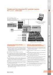
Advantages of the PG5 programming tools<br />
• Program portability: PG5 programs can run on all SAIA® PCD platforms.<br />
• Program organization by files (containing several program blocks) simplifies<br />
the shared use of program files between several SAIA®PCD controllers.<br />
• Programming and debugging environments united in each program editor.<br />
• Simple programming of terminal displays with the HMI Editor.<br />
• Powerful instruction set <strong>support</strong>ed by macros and assem bler directives.<br />
Features of the PG5<br />
• Symbol Manager administers all local, global and network symbols or symbol<br />
groups. Automatic address allocation largely dispenses with the need for<br />
fixed addressing.<br />
•Project Manager administers complex installations of networked PCDs, including<br />
displays and documentation.<br />
• Online functions for commissioning and error detection via Ethernet-TCP/IP,<br />
SAIA®S-Bus, modem, etc.<br />
• Integrated programming environments:<br />
– FUPLA (function block diagram)<br />
– S-Edit (instruction list IL)<br />
– GRAFTEC (sequential function chart)<br />
• Integrated network editors for SAIA®S-Bus, PROFIBUS DP, LONWORKS®.<br />
• Extensive additional libraries broaden the scope of PG5 functions.<br />
Edition 26/732 E11
Saia-Burgess Controls Ltd.<br />
I<br />
PG5-<strong>User</strong> <strong>Manual</strong> I Chapter 0 I Index I 23.09.10
II<br />
Saia-Burgess Controls Ltd.<br />
Contents<br />
1 PCD-Quick start<br />
2 Project Manager<br />
3 Device Configurateur<br />
4 PCD – Data Typ<br />
5 Symbol Editor<br />
6 Program with Fupla<br />
7 Program structures<br />
8 Graftec programming<br />
9 Programming in IL (Instruction List)<br />
10 Additional tools<br />
11 Saia Networks<br />
12 Profi-S-Bus<br />
13 Ether-S-Bus<br />
15 Profi-S-IO<br />
PG5-<strong>User</strong> <strong>Manual</strong> I Chapter 0 I Index | 23.09.10
Saia-Burgess Controls Ltd.<br />
III<br />
Preface<br />
This document is intended as an introduction to SaiaPCD programmable<br />
controllers, rather than as a detailed commissioning manual. It therefore concentrates<br />
on the essential points for users who wish to acquire practical expertise quickly. For<br />
more comprehensive information, please refer to the help supplied by the<br />
programming tool itself, or to the detailed manuals that will be found on the<br />
documentation CD.<br />
To ensure ideal conditions for your training, we advise you to obtain the following<br />
programs, documentation and material:<br />
• CD PG5 version 2.0<br />
• Documentation CD 26/803<br />
• 1 x PCD2. M5540 1 controller<br />
• 1 x PCD2.E110 module with 8 digital inputs<br />
• 1 x PCD2.A400 module with 8 digital outputs<br />
• 1 x USB cable<br />
All the necessary instructions for installing PG5 2.0 on your computer are provided on<br />
the PG5 version 2.0 CD (see under: CD:\ PG5_InstallationGuide_E.pdf).<br />
Please also note that all the English names of menus, instructions, options and<br />
buttons present in the PG5 program are reproduced in italics in this manual.<br />
We wish you every success with your training and with future projects involving<br />
SaiaPCD products.<br />
Your partner Saia-Burgess Controls Ltd.<br />
1 an other PCD may also be suitable<br />
PG5-<strong>User</strong> <strong>Manual</strong> I Chapter 0 I Index I 23.09.10
IV<br />
Saia-Burgess Controls Ltd.<br />
PG5-<strong>User</strong> <strong>Manual</strong> I Chapter 0 I Index | 23.09.10
Saia-Burgess Controls Ltd. 1-1<br />
Contents<br />
1 PCD – QUICK-START ................................................................................. 3<br />
1.1 Introduction ....................................................................................................................................3<br />
1.2 Preparing the hardware.................................................................................................................4<br />
1.2.1 Example: Stairway lighting ......................................................................................................4<br />
1.2.2 Connection diagram of PCD2.M5540 ......................................................................................4<br />
1.2.3 PCD2.M5540 assembly ............................................................................................................5<br />
1.2.4 Wiring.......................................................................................................................................5<br />
1.3 Editing the program.......................................................................................................................6<br />
1.3.1 Software Installation.................................................................................................................6<br />
1.3.2 Starting the PG5 .......................................................................................................................6<br />
1.3.3 Opening a new project..............................................................................................................7<br />
1.3.2 Opening an existing project......................................................................................................7<br />
1.3.4 Configuration............................................................................................................................8<br />
1.3.5 Adding a new program file.....................................................................................................10<br />
1.3.6 Opening an existing file..........................................................................................................11<br />
1.3.7 Editing a program...................................................................................................................11<br />
1.4 Running and testing the program ...............................................................................................15<br />
1.4.1 Building the program..............................................................................................................15<br />
1.4.2 Downloading the program into the PCD ................................................................................15<br />
1.5 Finding and correcting errors (Debugging)................................................................................16<br />
1.6 Correcting a program ..................................................................................................................17<br />
PG5 <strong>User</strong> <strong>Manual</strong> I Chapter 1 I Quick Start I 23.09.10
1-2 Saia-Burgess Controls Ltd.<br />
PG5 <strong>User</strong> <strong>Manual</strong> I Chapter 1 I Quick Start I 23.09.10
Saia-Burgess Controls Ltd. 1-3<br />
1 PCD – Quick-start<br />
1.1 Introduction<br />
As your first point of contact with PCD equipment, we propose a direct approach:<br />
tackling the production of a small real-life application. Even without any experience of<br />
Saia products, this is easy to do. Everything is set out in detail in this quick-start<br />
chapter.<br />
This example shows how to commission a PCD2.M5540. Programming and testing<br />
using the PG5 programming tools.<br />
Subsequent chapters in this document repeat in more detail the contents of this<br />
quick-start chapter, and provide much more information such as descriptions of<br />
available symbols, program structures and instruction list programming.<br />
PG5 <strong>User</strong> <strong>Manual</strong> I Chapter 1 I Quick Start I 23.09.10
1-4 Saia-Burgess Controls Ltd.<br />
1.2 Preparing the hardware<br />
1.2.1 Example: Stairway lighting<br />
The commissioning of a PCD is illustrated using stairway lighting as an example. The<br />
building has a ground floor and three upper storeys. Each level has a push-button for<br />
switching the lights on. By briefly pressing any of these buttons, all 4 lights in the<br />
stairway will be switched on for a period of 5 minutes.<br />
The push-buttons are connected to the 4 inputs of the PCD: I0, I1, I2 and I3.<br />
The 4 lights are switched on/off via a relay. The relay is controlled via a single output<br />
(O32) on the PCD.<br />
1.2.2 Connection diagram of PCD2.M5540<br />
Etage 3<br />
Etage 2<br />
Etage 1<br />
Rez-de-chaussée<br />
N<br />
P<br />
230 VAC<br />
PG5<br />
PCD2.E110<br />
PCD2.A400<br />
0 16 32 48<br />
–<br />
–<br />
+<br />
+<br />
+<br />
2<br />
:<br />
9<br />
:<br />
:<br />
:<br />
:<br />
:<br />
20<br />
112 96 80 64<br />
24 VDC<br />
+<br />
= / ~<br />
230 VAC<br />
PG5 <strong>User</strong> <strong>Manual</strong> I Chapter 1 I Quick Start I 23.09.10
Saia-Burgess Controls Ltd. 1-5<br />
1.2.3 PCD2.M5540 assembly<br />
1. Insert the supplied 3.0 V lithium battery.<br />
2. Plug a PCD2.E110 module into socket 1 (addresses 0 to 15).<br />
3. Push the module towards the middle of the device until the end stop and<br />
engage latch. This provides 8 digital inputs for 24 VDC with addresses I0 to<br />
I7. Only inputs I0 to I4 will be used.<br />
4. Plug a PCD2.A400 module into socket 3 (addresses 32 to 47) as previously<br />
described. This provides 8 digital outputs (O32 to O39) for 24 VDC / 0.5A.<br />
Only output O32 will be used.<br />
1.2.4 Wiring<br />
1. Connect the 24 VDC supply to screw terminals 20 (+) and 23 (–) .The<br />
following supply voltages are allowed: 24 VDC ±20% smoothed or 19 VAC<br />
±15% full-wave rectified<br />
2. The four inputs used are connected according to the hardware description of<br />
the PCD2.E110 module. Connect the 4 push-button switches to terminals 0 to<br />
3. Terminals 8 and 9 are connected to the power supply negative.<br />
3 st floor<br />
2 st floor<br />
1 st floor<br />
Ground floor<br />
+24 VDC<br />
–<br />
0<br />
E0<br />
1<br />
E1<br />
2<br />
E2<br />
3<br />
E3<br />
4<br />
E4<br />
5<br />
E5<br />
6<br />
E6<br />
7<br />
E7<br />
8<br />
L<br />
9<br />
–<br />
+ Module base address (=0 for this example)<br />
3. Connect terminal 0 to the relay coil , terminal 8 to the 24 VDC supply positive,<br />
and terminal 9 to the supply negative.<br />
3 rd floor<br />
2 nd floor<br />
1 st floor<br />
N<br />
230 VAC<br />
P<br />
Ground floor<br />
0<br />
A0<br />
1<br />
A1<br />
2<br />
A2<br />
3<br />
A3<br />
4<br />
A4<br />
5<br />
A5<br />
6<br />
A6<br />
7<br />
A7<br />
8<br />
+<br />
9<br />
–<br />
+24 VDC<br />
–<br />
4. Connect the PC’s USB interface to the PCD<br />
+ Module base address, , (+32 for this example)<br />
Note: For more detailed information about hardware assembly and wiring, please<br />
refer to your PCD hardware manual.<br />
PG5 <strong>User</strong> <strong>Manual</strong> I Chapter 1 I Quick Start I 23.09.10
1-6 Saia-Burgess Controls Ltd.<br />
1.3 Editing the program<br />
1.3.1 Software Installation<br />
Install the PG5 programming tool for Saia®PCD on the PC (if it has not already been<br />
installed), following the instructions supplied on the CD<br />
(CD:\ PG5_InstallationGuide_E.pdf).<br />
1.3.2 Starting the PG5<br />
Start the PG5's Project Manager:<br />
Start Programs Saia-Burgess PG5 Suite 2.0 Project Manager PG5<br />
The Saia Project Manager window is displayed. The Project Tree window shows the<br />
structure of the new project. (If this window is not shown, use the View, Project Tree<br />
menu command.)<br />
PG5 <strong>User</strong> <strong>Manual</strong> I Chapter 1 I Quick Start I 23.09.10
Saia-Burgess Controls Ltd. 1-7<br />
Folders in the Project Tree window contain project information, which is arranged<br />
according to certain criteria:<br />
• The name of the main folder shows the project name and the number of<br />
devices used in the project.<br />
• Files which are shared by several of the devices can be stored in the Common<br />
Files folder.<br />
• Next are the device folders (each device represents a PCD).<br />
Each device folder contains the following sub-folders:<br />
• Online Settings, Device Configurator and Build Options.<br />
• Program Files, contains the program module files.<br />
• Listing Files, contains files generated during the program build (Build). These<br />
are not so interesting to the inexperienced user.<br />
1.3.3 Opening a new project<br />
Before starting to write a new program, a new or existing project must be opened that<br />
contains the necessary definitions, a few configuration parameters and the files<br />
needed for the user program.<br />
If the project does not yet exist, select Project, New…, define the name of the new<br />
project in the Project Name field, check the Create Device option and confirm with the<br />
OK button.<br />
1.3.2 Opening an existing project<br />
A project which already exists can be opened using the Project, Open… menu<br />
command. This searches for all project files (.saia5pj) in the project directory, and<br />
displays them in a list. Double-click on the project in the list, or select the project from<br />
the list and press the Open button. Alternatively, you can press the Browse… button<br />
and find the project or device file directly.<br />
PG5 <strong>User</strong> <strong>Manual</strong> I Chapter 1 I Quick Start I 23.09.10
1-8 Saia-Burgess Controls Ltd.<br />
1.3.4 Configuration<br />
Before you can work with a device in the project, configuration parameters must be<br />
defined, so that the programming tools and the generated user program will work with<br />
the PCD.<br />
Under Online Settings, parameters can be set for communication between the PC<br />
and the PCD. Several possibilities are available. For this exercise the default protocol<br />
(PGU) will be selected, followed by the PC's serial port number (COM1).<br />
Channel S-Bus USB<br />
Define S-Bus USB<br />
protocol<br />
Select<br />
PGU<br />
Note:<br />
The USB interface is only<br />
available for the new CPUs:<br />
PCD2 and PCD3. For older<br />
devices, use the PGU<br />
interface (RS 232).<br />
Channel PGU (RS 232)<br />
Select PGU protocol<br />
Click on Setup<br />
Select the PC’s<br />
serial port RS<br />
232 to be<br />
connected to<br />
PG5 <strong>User</strong> <strong>Manual</strong> I Chapter 1 I Quick Start I 23.09.10
Saia-Burgess Controls Ltd. 1-9<br />
The Device Configurator defines the device type, memory size, S-Bus station<br />
number, communications interfaces, etc., but we won't describe all the options just<br />
yet. However, it is important to select the correct device type and memory size. The<br />
PCD2.M5540 is always supplied with a standard 1024 Kbyte RAM.<br />
To define a new device, select the correct PCD<br />
type from the Change Device Type context menu.<br />
The properties window is shown with<br />
the Properties context menu<br />
command. Here the memory size of<br />
can be defined.<br />
The configuration must always be downloaded into the PCD, using the menu<br />
command Online, Download Configuration…<br />
Check Memory Allocation too<br />
Download the<br />
configuration<br />
PG5 <strong>User</strong> <strong>Manual</strong> I Chapter 1 I Quick Start I 23.09.10
1-10 Saia-Burgess Controls Ltd.<br />
1.3.5 Adding a new program file<br />
PCD user programs are stored in one or more files. There are several ways of adding<br />
a program file:<br />
In the Project Tree window, select Program Files, click the right-hand mouse button to<br />
display the context menu and select New… (new file).<br />
Alternatively, you can click on the New File button on the toolbar, or use the File,<br />
New… menu command.<br />
In the New File window the name and type of the module are defined: two very<br />
important items of information.<br />
Several editors are available for writing PCD user programs. The user can choose<br />
which editor is best suited to the user program. For this example it is Fupla File<br />
(*.fup). Fupla is a general-purpose graphical programming language.<br />
PG5 <strong>User</strong> <strong>Manual</strong> I Chapter 1 I Quick Start I 23.09.10
Saia-Burgess Controls Ltd. 1-11<br />
1.3.6 Opening an existing file<br />
If the folder already contains a program file, the file can be opened as follows:<br />
In the Project Tree window, open the Program Files folder and double-click on the<br />
relevant file. Alternatively, right-click on the file name to open the context menu and<br />
select Open.<br />
Mark file or open it<br />
by double-clicking<br />
the mouse button<br />
Open file<br />
1.3.7 Editing a program<br />
PG5 <strong>User</strong> <strong>Manual</strong> I Chapter 1 I Quick Start I 23.09.10
1-12 Saia-Burgess Controls Ltd.<br />
Editing symbols<br />
Symbols reference the data needed by the PCD's user program, e.g. the stairway<br />
lighting switches. We edit symbols in the connectors on the Fupla page. ‘Read’<br />
symbols are on the left, ‘write’ symbols are on the right.<br />
This stairway lighting example has 4 light switches as inputs (I 0, I 1, I 2 and I 3) and<br />
one output (O 32) to drive the stairway lights. The required period of 5 minutes, during<br />
which stairway lighting will be on, must be entered in the input connector as a multiple<br />
of tenths of a second.<br />
The value of this constant is therefore 3000 (5 min. x 60 sec. x 10 = 3000).<br />
Add<br />
Connectors<br />
To add a connector and its symbol to a Fupla page, press the toolbar button Add<br />
Connector and position the mouse on the Fupla page. A ‘read’ input connector is<br />
added by clicking the left-hand mouse button. A ‘write’ output connector is added by<br />
holding down the Shift key and pressing the left-hand mouse button. The connector<br />
you have just added is ready to receive a symbol and a cursor is displayed inside the<br />
connector. If you do not wish to edit the symbol inside the connector straight away,<br />
press the ESC key and place the next connector.<br />
To edit or modify a connector symbol already present on the Fupla page, select the<br />
connector by double clicking quickly. A cursor will be displayed inside the connector.<br />
It is now possible to enter the address I 0 to I 3, or output O 32, or the constant. Make<br />
sure you always leave a space between the letter I and the input address. The same<br />
applies for the output.<br />
Show Hide<br />
Symbols Editor<br />
To edit the input symbols, 4 consecutive cells in the left-hand column of the program<br />
screen are marked with the mouse and addresses I 0 to I 3 are entered. The time<br />
constant 3000 (left) and output O 32 (right) are entered in the same way.<br />
Please note that the address type (I or O) and address value (0 to 3 and 32) must be<br />
separated by a space character.<br />
The symbols will immediately appear in the Symbols window of the Symbol Editor. If<br />
the symbol editor is not visible it can be displayed using the View, Symbols menu<br />
command or by pressing the Show/Hide Symbol Editor toolbar button:<br />
Note: By default, each new page may already provide margins with connectors on the<br />
left and right. If you prefer new pages not to appear with these connectors, so that<br />
you can place them wherever you want, just turn off the relevant option with menu<br />
command: View, Options…, Workspace, New pages with side connectors.<br />
To remove any empty connectors present on the left or right of the page, select<br />
menu: Page, Remove Unused Connectors.<br />
To place connectors once again on a blank page, select menu: Page, Add Side<br />
Connectors.<br />
PG5 <strong>User</strong> <strong>Manual</strong> I Chapter 1 I Quick Start I 23.09.10
Saia-Burgess Controls Ltd. 1-13<br />
Editing program functions<br />
Program functions are inserted in the area between the ‘read’ and ‘write’ connectors.<br />
This is done by positioning the graphical symbols of the function boxes (FBoxes) that<br />
are used to create user programs.<br />
Function boxes are selected from the FBox Selector window.<br />
Show/Hide<br />
The first function required in this example serves to switch on the lighting in response<br />
to a short pulse from a stairway switch. This is an OR function, which is found in the<br />
Binary family.<br />
The second function Off delay defines the 5 minute period during which the lights are<br />
on. It is found in the Time related family.<br />
Further information about the FBox can be found by right-clicking on the function in<br />
the FBox Selector window, and choosing the FBox Info context menu command.<br />
When a function box has been selected from the FBox Selector window, the left-hand<br />
mouse button is used to place it in the edit window between symbol columns.<br />
With certain function boxes, such as OR logic, the number of inputs can be selected.<br />
This is done by dragging the mouse vertically and clicking the left-hand mouse button<br />
when the number of inputs is correct.<br />
PG5 <strong>User</strong> <strong>Manual</strong> I Chapter 1 I Quick Start I 23.09.10
1-14 Saia-Burgess Controls Ltd.<br />
Connecting function<br />
Use this method when connection points are aligned horizontally<br />
1. Press the Select Mode button<br />
2. Place the mouse pointer over the FBox and press<br />
the left-hand mouse button.<br />
3. Hold the button down and drag the FBox<br />
horizontally until the connection is made. Do not<br />
release the mouse button.<br />
4. Drag the FBox back to its original position and<br />
release the mouse button.<br />
3.<br />
2.<br />
4.<br />
1.<br />
Use this method for the other connections<br />
1. Press the Line Mode button<br />
2. Click on the starting point with the left-hand mouse<br />
button and release it. Move the mouse pointer to<br />
the right as far as required and press the left-hand<br />
mouse button again.<br />
3. Move the mouse vertically and click the left mouse<br />
button once more.<br />
4. Move the mouse pointer to the FBox connector and<br />
press the left-hand mouse button again to finalise<br />
the connection.<br />
5. If necessary, line drawing can be aborted by<br />
pressing the right-hand mouse button.<br />
2. 3.<br />
1.<br />
4.<br />
Deleting a line, function box, symbol or connector<br />
Press the Delete Object toolbar button and click on the<br />
line, FBox, Symbol or Connector to be deleted.<br />
PG5 <strong>User</strong> <strong>Manual</strong> I Chapter 1 I Quick Start I 23.09.10
Saia-Burgess Controls Ltd. 1-15<br />
1.4 Running and testing the program<br />
1.4.1 Building the program<br />
Before the program can be executed by the PCD, it must be built (compiled,<br />
assembled and linked) using the Project Manager's Device, Build Changed Files<br />
menu command, or the Rebuild All Files toolbar button.<br />
Rebuild<br />
All Files<br />
The results of the build are shown in the Messages window (Compiling, Assembling,<br />
Linking etc.). If the program has been correctly edited, the build function completes<br />
with the message: Build successful. Total errors 0 Total warnings: 0<br />
Errors are indicated by a red error message. Most errors can be located in the user<br />
program by double-clicking on the error message.<br />
1.4.2 Downloading the program into the PCD<br />
The user program is now ready. All that remains is to download it from the PC into the<br />
PCD. This is done using Project Manager's Download Program toolbar button or the<br />
Online, Download Program menu command.<br />
Download<br />
Program<br />
If any communications problems arise, check the Online Settings and the cable<br />
connection between the PC and the PCD (PCD8.K111 or USB).<br />
PG5 <strong>User</strong> <strong>Manual</strong> I Chapter 1 I Quick Start I 23.09.10
1-16 Saia-Burgess Controls Ltd.<br />
1.5 Finding and correcting errors (Debugging)<br />
The first version of a program is rarely perfect. A stringent test is always needed.<br />
Program testing is done using the same editor that was used to write the program.<br />
1. Press the Go On /Offline button<br />
2. Start program with the Run button<br />
Observe the Run LED on the PCD at the same time.<br />
When the Run button is pressed, the Run LED on the PCD should turn on because<br />
the PCD is now executing the user program.<br />
When the Stop button is pressed, the Run LED on the PCD should turn off because<br />
the PCD has stopped executing the program.<br />
When the editor is Online and the PCD is in Run mode, the state of each individual<br />
symbol can be displayed:<br />
• The logical state of binary data is shown with a heavy or fine line (heavy = 1 and<br />
fine = 0)<br />
• Other data values can be displayed by clicking the left-hand mouse button on the<br />
connection to show a Probe window: use the mouse to select the Add Probe<br />
button and the link.<br />
PG5 <strong>User</strong> <strong>Manual</strong> I Chapter 1 I Quick Start I 23.09.10
Saia-Burgess Controls Ltd. 1-17<br />
1.6 Correcting a program<br />
To modify a program, proceed as follows:<br />
1. Go offline (using the Go On /Offline button).<br />
2. Modify the program.<br />
3. Build the new program (with the Build button).<br />
4. Download program to the PCD with the Download Program<br />
button.<br />
PG5 <strong>User</strong> <strong>Manual</strong> I Chapter 1 I Quick Start I 23.09.10
1-18 Saia-Burgess Controls Ltd.<br />
PG5 <strong>User</strong> <strong>Manual</strong> I Chapter 1 I Quick Start I 23.09.10
Saia-Burgess Controls SA 2-1<br />
Contents<br />
2 PROJECT MANAGEMENT ......................................................................... 2<br />
2.1 Project Organisation ......................................................................................................................2<br />
2.1.1 Opening a Project .....................................................................................................................3<br />
2.1.2 Creating a new Project..............................................................................................................3<br />
2.1.3 How projects are stored on the PC ...........................................................................................4<br />
2.1.4 Backup and restore of a Project or Device ...............................................................................5<br />
2.2 The Project Tree window................................................................................................................6<br />
2.2.1 Project folder............................................................................................................................6<br />
2.2.2 Common Files folder................................................................................................................7<br />
2.2.3 Libraries folder .........................................................................................................................7<br />
2.2.4 Device folder ............................................................................................................................8<br />
2.2.5 Online Settings..........................................................................................................................9<br />
2.2.6 Connecting the PC to the PCD ...............................................................................................10<br />
2.2.7 Device Configurator...............................................................................................................11<br />
2.2.8 Build Options..........................................................................................................................11<br />
2.2.9 Program Files folder ...............................................................................................................13<br />
2.2.10 File Types ...............................................................................................................................15<br />
2.3 Building the Program...................................................................................................................17<br />
2.3.1 Build Changed Files, Rebuild All Files, Rebuild All Devices.................................................18<br />
2.3.2 General Build Options ............................................................................................................18<br />
2.4 Messages Window.........................................................................................................................19<br />
2.5 Downloading the Program into the PCD....................................................................................20<br />
2.5.1 Download Program ................................................................................................................20<br />
2.5.2 Download Options..................................................................................................................21<br />
2.6 Commands for All Devices...........................................................................................................22<br />
2.7 Self Downloading Files .................................................................................................................23<br />
2.7.1 Creating a self-downloading file ............................................................................................23<br />
2.7.2 Downloading a self-downloading file.....................................................................................24<br />
2.8 Flash Backup Memory .................................................................................................................25<br />
2.8.1 Saving the executable program...............................................................................................25<br />
2.8.2 Saving the program's source code...........................................................................................25<br />
2.8.3 Backing up data to a file.........................................................................................................28<br />
2.9 The View Windows .......................................................................................................................29<br />
2.9.1 Block Call Structure ...............................................................................................................29<br />
2.9.2 Global Symbols and Data List Views.....................................................................................30<br />
2.9.3 Cross-Reference List ..............................................................................................................30<br />
2.10 The Online Configurator .............................................................................................................31<br />
2.10.1 Device Configurator ...............................................................................................................31<br />
2.10.2 PCD History ...........................................................................................................................32<br />
2.10.3 Setting the PCD's Clock .........................................................................................................32<br />
2.10.4 Saving program and data from RAM .....................................................................................33<br />
2.10.5 Create Diagnostic File ...........................................................................................................33<br />
PG5 <strong>User</strong> <strong>Manual</strong> I Chapter 2 I Project Management I 23.09.10
2-2 Saia-Burgess Controls SA<br />
2.10.6 Firmware Downloader............................................................................................................33<br />
2 Project Management<br />
2.1 Project Organisation<br />
Modern automation processes usually contain several devices connected in a<br />
network, where each device carries out a particular function. For example, a building<br />
control system might have dedicated devices for handling lighting, heating,<br />
ventilation, automatic doors in the underground garage, etc.<br />
Active Device<br />
The PG5 Project Manager provides a global view of all the devices and files in a<br />
single project. All operations are started from here. For example, adding new program<br />
files to the project, opening files to write the programs, configuring the hardware,<br />
building and downloading the programs into the devices, backup and restore,<br />
reporting errors and warnings when building the program, etc.<br />
The Project Tree window shows a hierarchical representation of each device and its<br />
configuration and program files. To display this window use the View, Project Tree<br />
menu command.<br />
PG5 <strong>User</strong> <strong>Manual</strong> I Chapter 2 I Project Management I 23.09.10
Saia-Burgess Controls SA 2-3<br />
The Messages window shows general information messages, and error and warning<br />
messages generated when building a program. Display this window with the View,<br />
Messages menu command.<br />
The other View windows show lists of symbols and media used, and the program<br />
structure. They also provide a symbol cross-reference feature.<br />
The active device is marked with a green triangle. Many of the menus and Tool Bar<br />
buttons work on the active device. To change the active device, just select another<br />
device in the Project Tree, or use the Device, Set Active menu command.<br />
2.1.1 Opening a Project<br />
The PG5 is installed with all the examples in this manual. The Project, Open…<br />
command displays a list of all projects by finding all the project files (.saia5pj) in the<br />
Projects Directory. Double-click on the project to open it, or select the project and<br />
press the Open button. Alternatively you can press the Browse… button and find a<br />
specific project or device file (.saia5pc) in another directory.<br />
Folder containing the<br />
projects listed below<br />
Selected project<br />
2.1.2 Creating a new Project<br />
To start a new project, use the Project, New… menu command, enter the name of the<br />
project in the Project Name field (default = ProjectX) and press OK.<br />
PG5 <strong>User</strong> <strong>Manual</strong> I Chapter 2 I Project Management I 23.09.10
2-4 Saia-Burgess Controls SA<br />
Project Name: The name of the new project.<br />
Projects Directory: Name of folder which will contain the project.<br />
Description: Free text, description of the project.<br />
Create Device: Automatically creates a single device with the same name as<br />
the project.<br />
2.1.3 How projects are stored on the PC<br />
By default, all projects are stored in the following project directories, depending on the<br />
Windows version:<br />
XP: C:\Documents and Settings\All <strong>User</strong>s\Documents\Saia-Burgess\ PG5 2_0\Projects<br />
Vista: C:\<strong>User</strong>s\Public\Documents\Saia-Burgess\ PG5 2_0\Projects<br />
If necessary, the project (and library) directories can be changed using the Tools, Options…<br />
menu command:<br />
The project is saved in a directory with<br />
the same name as the project. Each<br />
device is stored in a subdirectory of<br />
the project folder.<br />
PG5 <strong>User</strong> <strong>Manual</strong> I Chapter 2 I Project Management I 23.09.10
Saia-Burgess Controls SA 2-5<br />
2.1.4 Backup and restore of a Project or Device<br />
To backup a project it is necessary to keep the same folder structure and all the<br />
source files which comprise the project. The Project, Backup… menu command<br />
compresses either the entire project or just a single device into a standard ".zip" file,<br />
which can be restored using the Project, Restore… command.<br />
Project, Backup…<br />
Project, Restore…<br />
Backup Project or Single Device<br />
Selects whether the entire project, or just a single device in the project will be backed<br />
up. By default it is the entire project.<br />
To Compressed File<br />
The path of the compressed ".zip" file which will be created. The default name<br />
contains the project or device name plus the date/time in the format:<br />
d:\\_yyyymmdd_hhmm.zip<br />
Comment<br />
Free text describing the backup. By default this is filled in with the user name, project<br />
name and date/time of the backup.<br />
Backup What<br />
Defines which will be saved. It's not necessary to save all the files, only the source ad<br />
configuration files are important.<br />
Diskette Options<br />
Please use a USB memory stick instead of a diskette!<br />
PG5 <strong>User</strong> <strong>Manual</strong> I Chapter 2 I Project Management I 23.09.10
2-6 Saia-Burgess Controls SA<br />
2.2 The Project Tree window<br />
Device context menu<br />
Displayed by the View, Project Tree command, the Project Tree provides a structured<br />
view or the project information.<br />
2.2.1 Project folder<br />
The top-level folder represents the project, with its name and the number of devices it<br />
contains. Use these commands to manage devices in the project:<br />
Main menu Device, New… or context menu New Device…<br />
Creates an adds a new device to the project.<br />
Main menu Device, Import… or context menu Import Device…<br />
Imports an existing device from another project. If a device is imported from an old<br />
PG4 or PG5 version, it will be converted to the new V2 format.<br />
Main menu File, Properties... or context menu Properties…<br />
Display or modify a project's properties: name, description and read-only attribute.<br />
PG5 <strong>User</strong> <strong>Manual</strong> I Chapter 2 I Project Management I 23.09.10
Saia-Burgess Controls SA 2-7<br />
2.2.2 Common Files folder<br />
Drag&Drop<br />
This folder contains files that can be shared by more than one device in the project.<br />
These files can be copied, pasted or dragged into the Program Files folder of each<br />
device which shares them. A common file's name shown in the Program Files folder<br />
begins with two dots "..\", which indicates that the file is in the parent directory, one<br />
level up.<br />
The file can be opened from either the Common Files or the Program Files folders. In<br />
both cases the same file can be modified and the changes effect every device which<br />
references the file.<br />
These are the main commands you will need for adding common files:<br />
File, New… or context menu New File…<br />
Creates and adds a new file to the Common Files folder.<br />
Context menu Add Files…<br />
Copies one or more existing files into the Common Files directory. Not only PG5<br />
program files, but also commissioning and maintenance documents (Word and Excel<br />
files etc.) can be added. These files are stored with the PG5 project and can be<br />
opened from the Project Tree by double-clicking on them.<br />
2.2.3 Libraries folder<br />
This folder opens the Library Manager window which shows all the available libraries.<br />
The Installed Libraries list shows all the libraries found in the library files directory,<br />
which can be used by all projects.<br />
The Libraries Copied To Project list shows the libraries which have been copied to the<br />
open project's local libraries subdirectory. Only the open project can use these<br />
libraries. Installed libraries can be copied into the project using drag-and-drop or by<br />
selecting the library and pressing the Copy To Project button.<br />
<strong>User</strong>'s libraries or versions which are not distributed as standard with the PG5 should<br />
always be saved with the project, to guarantee that the project is complete and will<br />
always build.<br />
If different versions of the same library are present, the library to be used for the build<br />
can be selected with the checkboxes in the Used column.<br />
PG5 <strong>User</strong> <strong>Manual</strong> I Chapter 2 I Project Management I 23.09.10
2-8 Saia-Burgess Controls SA<br />
2.2.4 Device folder<br />
Each device folder contains the configuration and files for a single controller.<br />
These are the main commands you will need for managing devices:<br />
Context menu Device, Set Active<br />
Activates the device selected in the Project Tree. The active device is indicated by a<br />
green triangle, and many main menu and Tool Bar buttons work on the active device.<br />
Note: This command is only shown if the option Tools, Options…, Project Manager<br />
Activate Device according to Project Tree location is set to No. If Yes, then the Project<br />
Manager will automatically active the device according to the selection in the Project<br />
Tree.<br />
File, Properties… or context menu Properties…<br />
Display or modify the properties of a device: name, description, read-only option.<br />
[Edit,] Copy, Paste, Delete<br />
Copy/Paste allows an entire device to be duplicated in the project, with all its files and<br />
configuration. Delete removes a device and all its files to the Recycle Bin.<br />
PG5 <strong>User</strong> <strong>Manual</strong> I Chapter 2 I Project Management I 23.09.10
Saia-Burgess Controls SA 2-9<br />
2.2.5 Online Settings<br />
This branch opens the Online Settings window which defines the communications for<br />
connecting to the PCD. Several protocols are available: PGU, S-Bus, S-Bus USB,<br />
etc., but only the PGU and S-Bus USB allow the full protocol communications needed<br />
by the Device Configurator.<br />
Channel S-Bus USB<br />
S-Bus USB<br />
channel selected<br />
Select PGU<br />
mode = Yes<br />
Note:<br />
The USB connection is only<br />
available on the new PCD2 and<br />
PCD3 devices. For old devices<br />
use the PGU channel (RS 232).<br />
Remarque:<br />
l’interface USB n’est disponible que sur les nouveaux devices PCD2 et PCD3.<br />
Channel PGU (RS 232)<br />
PGU channel selected<br />
Build Changed<br />
Fil<br />
Defines the serial<br />
port (RS 232) of<br />
the PC which is<br />
connected to the<br />
PCD.<br />
The Add button allows new channels to be created with their own types and<br />
parameters. These are then visible in the Online Settings list of Channels.<br />
PG5 <strong>User</strong> <strong>Manual</strong> I Chapter 2 I Project Management I 23.09.10
2-10 Saia-Burgess Controls SA<br />
2.2.6 Connecting the PC to the PCD<br />
Channel S-Bus USB<br />
The USB connection is only available for the new PCD2 and PCD3 devices. Use any<br />
standard USB cable.<br />
Channel PGU (RS 232)<br />
Use the PCD8.K111 cable.<br />
PCD8.K111<br />
The wiring of this cable is described in the relevant PCD hardware manual.<br />
Online<br />
Configurator<br />
Verifying the connection<br />
Use the Online Configurator toolbar button or menu command to connect to the PCD<br />
and display its details. If the information in red is shown then the connection is<br />
working properly (the details will vary according to the connected PCD).<br />
If the connection cannot be made, an<br />
error message like this is displayed.<br />
Check the PCD has power, and verify the<br />
Online Settings and the cable<br />
connection.<br />
PG5 <strong>User</strong> <strong>Manual</strong> I Chapter 2 I Project Management I 23.09.10
Saia-Burgess Controls SA 2-11<br />
2.2.7 Device Configurator<br />
The Device Configurator defines the hardware and physical features of the controller,<br />
such as the device type, memory, communications channels, fitted modules and I/Os,<br />
etc. It also verifies that the power supply provides enough power, and it can print<br />
labels for the I/O modules.<br />
To commission a PCD, it is necessary to configure at least the PCD type and its<br />
memory size. Other items such as communications and I/Os can be configured later.<br />
The easiest way to start the configuration is to connect the PCD with the USB or<br />
PCD7.K111 cable, and read the actual configuration from the PCD using the Online,<br />
Upload Configuration… menu command or corresponding toolbar button.<br />
If the PCD's memory has not been configured, it may show default settings, so please<br />
always verify that this matches your hardware and application.<br />
2.2.8 Build Options<br />
These options are used when the user program is built.<br />
Media Allocation<br />
This section reserves address ranges for dynamic Registers, Counters, Timers and<br />
Flags. When the program is built, addresses are automatically assigned to dynamic<br />
symbols defined in the user program and Fupla FBoxes.<br />
A dynamic symbol is one for which no absolute address has been defined:<br />
Dynamic address<br />
It is not always necessary to change the dynamic address ranges. The default<br />
settings are usually adequate for most applications.<br />
However, if an error message like this appears during the building of a large program:<br />
Fatal Error 2368: Dynamic space overflow for type: R<br />
PG5 <strong>User</strong> <strong>Manual</strong> I Chapter 2 I Project Management I 23.09.10
2-12 Saia-Burgess Controls SA<br />
then it will be necessary to extend the dynamic address range for the media type<br />
shown in the error message.<br />
If the controller is fitted with EPROM or Flash for main memory, then the RAM Texts<br />
and RAM DB dynamic ranges must be configured from address 4000 upwards, so<br />
that these Texts and DBs are in writeable RAM memory.<br />
Last Timer<br />
Timers and Counters share the same address ranges. The Last Timer value defines<br />
the partition between Timers and Counters (it generates the DEFTC instruction).<br />
Dynamic Timer addresses must be below or up to this value, and dynamic Counter<br />
addresses must be above. For example, if Last Timer is 31, then Timers are T 0..31<br />
and Counters are C 32..1599.<br />
Timer Timebase in milliseconds<br />
The default timebase at which Timers decrement is once every 0.1 seconds (100ms).<br />
If necessary this can be set to another value. Note that the timebase has no influence<br />
on Fupla programs. Only IL programs are affected by this parameter.<br />
NOTE: Do not to define an unnecessarily large number of Timers or an unnecessarily<br />
small timebase, because this will slow down your program's cycle times.<br />
Dynamic Nonvolatile Flags<br />
By default, all Flags are non-volatile. Volatile Flags are always set to 0 at start-up,<br />
nonvolatile Flags retain their values. If necessary, the Last Volatile Flag parameter<br />
allows a volatile range to be defined. (The picture above shows Volatile Flags for<br />
addresses F 0 to F 2999.)<br />
PG5 <strong>User</strong> <strong>Manual</strong> I Chapter 2 I Project Management I 23.09.10
Saia-Burgess Controls SA 2-13<br />
2.2.9 Program Files folder<br />
This folder holds the files that make up the device's program. These are the main<br />
commands you will need for managing program files:<br />
File, New… or context menu New File…<br />
Creates and adds a new file to the folder:<br />
File Name: Name of the file to be created.<br />
Directory: Directory of the device, cannot be edited.<br />
File Type: The type of file to be created.<br />
Description: Free text which can be used for a description of the file, history, version<br />
information etc.<br />
Linked/Built: If not checked then the file will be ignored by the build. It will not be part<br />
of the user program.<br />
Open File Now: Checked by default, the file will be opened immediately in the<br />
associated editor.<br />
Device, Add Files… or context menu Add Files…<br />
Adds one or more files to Program Files list. Files can be copied into the device<br />
directory, or can be linked by a path, according to the Copy files into device directory<br />
option on the Add Files dialog box.<br />
File, Properties… or context menu Properties…<br />
PG5 <strong>User</strong> <strong>Manual</strong> I Chapter 2 I Project Management I 23.09.10
2-14 Saia-Burgess Controls SA<br />
Display or modify the selected file's properties: name, description, Linked/Built and<br />
Read Only and Symbol File options. Check Symbol File if the file contains only the<br />
definitions of Global symbols.<br />
[Edit,] Copy, Paste, Delete<br />
Copy/Paste allows a file to be duplicated in the current Program Files list or any<br />
device in the project. Delete removes a device and all its files to the Recycle Bin.<br />
Files which comprise the device<br />
Select the file and uncheck<br />
the context menu's<br />
Linked/Built option<br />
Files with an arrow in the icon are processed by the build. These files are part of the<br />
PCD's program and their code and data are loaded into the PCD's memory.<br />
Files without an arrow on the icon are not processed by the build. These files are<br />
ignored and are not downloaded into PCD memory. This can be useful for test and<br />
commissioning code which will not be present in the final program.<br />
PG5 <strong>User</strong> <strong>Manual</strong> I Chapter 2 I Project Management I 23.09.10
Saia-Burgess Controls SA 2-15<br />
2.2.10 File Types<br />
A device can have several program files of different types. Each type of file has a<br />
corresponding editor for a specific field of application.<br />
Instruction List Editor (*.src)<br />
Allows programming in text form using IL instructions.<br />
Suitable for all applications. Code is fast and efficient,<br />
but it requires a lot of programming experience.<br />
COB 0<br />
0<br />
STH I 0<br />
DYN F 9<br />
INC C 53<br />
ECOB<br />
Fupla Editor (*.fup)<br />
Allows programs to be drawn in the form of function plans<br />
and contact diagrams. Requires no programming experience.<br />
Many libraries are available for the rapid implementation of<br />
HEAVAC applications and communications networks<br />
(modem, LON, Belimo, EIB, etc.).<br />
Graftec Editor (*.sfc)<br />
This is a tool for structuring programs in IL (instruction list)<br />
and Fupla. Particularly suitable for sequential applications<br />
with waits for internal or external events.<br />
It is the ideal tool for programming machines with<br />
commands for motors, actuators, etc.<br />
HMI Editor (*.hmi)<br />
Allows configuration of simple menus with PCD7.D1xx<br />
and PCD7.D2xx terminals (installed in addition to<br />
PG5).<br />
PG5 <strong>User</strong> <strong>Manual</strong> I Chapter 2 I Project Management I 23.09.10
2-16 Saia-Burgess Controls SA<br />
Web Editor (*.prj)<br />
Editor of web pages for process monitoring and<br />
control. Pages can be stored inside a PCD, a web<br />
panel (PCD7.Dxxx) or on the hard drive of the PC.<br />
Web panels and PCs display the pages on a standard<br />
browser such as Internet Explorer, and can use any<br />
network for communications.<br />
S-Net Network Configurator (*.dp, *.lon, *.srio)<br />
For configuring device networks and communications:<br />
Profibus DP, LON et SRIO.<br />
PG5 <strong>User</strong> <strong>Manual</strong> I Chapter 2 I Project Management I 23.09.10
Saia-Burgess Controls SA 2-17<br />
2.3 Building the Program<br />
Sources files:<br />
The PCD cannot directly process the text files created by the editors. These files must<br />
first be compiled and/or assembled, and then linked to create a binary executable<br />
".pcd" file, as shown in the diagram below.<br />
• Graphical Editors<br />
1. Compile<br />
Rebuild All<br />
or<br />
Build<br />
• IL files<br />
2. Assemble<br />
• Object and listing files<br />
Print<br />
3. Link<br />
• Binary PCD File<br />
Download<br />
Program<br />
4. Device, Advanced,<br />
Create Documentation<br />
• PCD Controller<br />
Print<br />
1. Compilation converts graphical files into Instruction List files (*.fbd, *.src, *.hsr)<br />
2. Assembling produces binary object files (*.obj), and an assembly report (*.lst)<br />
which can be printed or used for troubleshooting certain assembler errors.<br />
3. Linking combines object files (*.obj) to form a single binary executable file (*.pcd)<br />
for downloading into the PCD.<br />
4. IL documentation files are generated by the Project Manager's Device, Advanced,<br />
Create Documentation command. The resulting files are shown in the<br />
Documentation Files folder.<br />
PG5 <strong>User</strong> <strong>Manual</strong> I Chapter 2 I Project Management I 23.09.10
2-18 Saia-Burgess Controls SA<br />
2.3.1 Build Changed Files, Rebuild All Files, Rebuild All Devices<br />
Rebuild<br />
All<br />
The Device, Rebuild All Files command starts the compilation, assembling and linking<br />
of all the Linked/Built files for the active device.<br />
The Device, Build Changed Files command does the same thing but only for the files<br />
modified since the last build. This is much faster, especially for big programs.<br />
Build Changed<br />
Files<br />
The Project, Rebuild All Programs… command does a Rebuild All Files for each<br />
device in the project. Once complete, the Messages window shows the number of<br />
devices built with and without errors. Double-click on the red Build Errors message to<br />
move to the error messages for that device.<br />
2.3.2 General Build Options<br />
The build options which are shared by all projects and devices are configured from<br />
the Tools, Options command, Build section.<br />
Ask before saving changed files<br />
If Yes, the PG5 requests authorization to save source files which have been changed<br />
but not saved before building the program. If No, files are saved automatically.<br />
Stop build on first error<br />
Set to Yes to stop the build when the first error appears in the Messages window.<br />
Download program after successful build<br />
When Yes, the program is automatically downloaded into the PCD after every<br />
successful build.<br />
Download without confirmation<br />
Normally the download starts with a dialog box notifying the user, and the download<br />
must be started by pressing the Download button. If this option is Yes, then the<br />
download starts immediately without displaying the dialog box. This options is<br />
disabled unless Download program after successful build is selected.<br />
Clear message window on build<br />
The contents of the Messages window is deleted at the start of every build.<br />
Create Listing files (.lst)<br />
Creates and assembler report file (.lst). These can be viewed the Listing Files folder.<br />
Create Map file (.map)<br />
Creates the linker report file (.map). This can be viewed the Listing Files folder.<br />
PG5 <strong>User</strong> <strong>Manual</strong> I Chapter 2 I Project Management I 23.09.10
Saia-Burgess Controls SA 2-19<br />
2.4 Messages Window<br />
The Messages window provides information on the progress of a program build. It<br />
notes the different stages of the build: compilation, assembling and linking. If the<br />
program has been edited correctly, the build ends with the message:<br />
Build successful. Total errors 0 Total warnings: 0<br />
Errors are indicated with a message in red. Double-clicking on an error message will<br />
open the editor and select the location of the error, if possible.<br />
Selecting the error message and pressing F1 will display help on the error, if it's<br />
available.<br />
Error is marked in<br />
red or by an arrow<br />
Error has been<br />
corrected<br />
PG5 <strong>User</strong> <strong>Manual</strong> I Chapter 2 I Project Management I 23.09.10
2-20 Saia-Burgess Controls SA<br />
2.5 Downloading the Program into the PCD<br />
2.5.1 Download Program<br />
Download<br />
Program<br />
If the build is successful, the Online, Download Program command or toolbar button<br />
will download the executable program into the PCD's memory.<br />
Program File Name<br />
By default, this is the path of the active device's PCD file.<br />
All<br />
Downloads the entire program (Code, Text/DB, Extension Memory, Downloadable<br />
Files)<br />
Changed Blocks<br />
Downloads only the blocks (COB, PB, FB, SB, ST, TR, XOB) which have changed<br />
since the last download. This option should only be used to save time when<br />
downloading minor corrections while developing a program. The Changed Blocks<br />
button can be used to display a list of changed blocks. See help for more details.<br />
Download in Run<br />
Allows changed blocks to be downloaded without halting program execution. Proper<br />
operation of the program depends on what changes have been made – see Help for<br />
details.<br />
Do NOT use this option unless you are sure that the changes are correct.<br />
Selected Segments<br />
Only downloads the sections defined by the Selected Segments options:<br />
Code Segment = Program, Text/DB Segment = Texts and DBs 0…3999, Extension<br />
Memory = Texts and DBs 4000+, Downloadable files = Configuration files such as<br />
BacNet configuration.<br />
First-time Initialisation Data<br />
Specific media (R T C F) can be initialised when the program is downloaded. Firsttime<br />
initialisation data is defined using :=<br />
symbol EQU type [address] := initialisation_value<br />
or<br />
First-time initialisation data is not initialised every time the program starts, but only<br />
when a new program starts. Other data can be initialised by code in the start-up XOB<br />
16.<br />
Copy <strong>User</strong> Program to Flash<br />
PG5 <strong>User</strong> <strong>Manual</strong> I Chapter 2 I Project Management I 23.09.10
Saia-Burgess Controls SA 2-21<br />
Once the program has been successfully downloaded into RAM memory, it will be<br />
saved in backup Flash memory, if fitted.<br />
2.5.2 Download Options<br />
Additional download options can be defined with the Tools, Options menu command,<br />
or the Options button on the Download Program dialog box. They allow the program<br />
download procedure to be personalized.<br />
Download program only if changed<br />
Does not download unchanged programs. There is no need to download a program<br />
which has not changed.<br />
Download only the changed blocks<br />
See previous page.<br />
Verify all PCD memory writes<br />
All data written to the PCD will be read back and compared. This option should not<br />
normally be selected, because it doubles the program download time. Use it only if<br />
you suspect a rare problem with the PCD's memory chip.<br />
Run the program after successful download<br />
Automatically puts the device into Run after downloading the program.<br />
WARNING: This option should only be selected if you are sure the program will run<br />
correctly, or there is no possible risk to people or property if it fails.<br />
Go online after successful download<br />
Automatically puts the device online after a successful download.<br />
Backup user program to Flash after download<br />
Automatically copies the program to Flash 1 backup memory.<br />
If this option has not been selected, a copy can still be made after the download,<br />
using the Online, Flash Memory, Copy Program To Flash command.<br />
Warn if PCD contains program with different name<br />
Compares the name of the program in the PCD with the name of the program to be<br />
downloaded. If the program names differ, a message will be displayed to prevent<br />
downloading into the wrong PCD.<br />
Warn if a running program will be stopped<br />
Downloading a program will stop the PCD. Depending on the application or process,<br />
it could be dangerous to stop a running program, e.g. if it's controlling a Large Hadron<br />
Collider or nuclear power station. Selecting this option allows a warning message to<br />
be displayed before the program is stopped.<br />
Do not clear Outputs on download or restart<br />
1) PCD2.M170, PCD2.M480, PCD4.M170 et PCD3<br />
PG5 <strong>User</strong> <strong>Manual</strong> I Chapter 2 I Project Management I 23.09.10
2-22 Saia-Burgess Controls SA<br />
This option can be useful with HEAVAC applications. It prevents ventilation or lighting<br />
from being switched off while a program is being downloaded. It should not be<br />
selected with other applications.<br />
Auto close Up/Download dialog boxes on success<br />
If this option is selected, the Up/Download dialog boxes close automatically after a<br />
successful download, and will only remain open if there was an error.<br />
2.6 Commands for All Devices<br />
If the PC and all the project's devices are connected together on a network, then<br />
Project, Online Commands dialog box provides some useful commands for controlling<br />
or downloading to all devices on the network.<br />
The dialog box shows a list of all devices in the project, and has checkboxes for<br />
selecting the devices to receive the commands. By default all devices are checked.<br />
The device list's context menu contains some commands for manipulating these<br />
checkboxes.<br />
Options, Device Sequence<br />
By default, commands are sent to the devices in the order in which they are defined in<br />
the Project Tree (alphabetical order). This option displays a dialog box which allows<br />
the order to be changed.<br />
Options, Options For 'Download Programs'<br />
Believe it or not, this configures the options for the Download Programs command.<br />
NOTE: Some of these options could be very important, they define when the devices<br />
will be put into Stop or Run.<br />
Commands, Test<br />
This command verifies that each selected device is online and able to receive<br />
commands. If it fails, check the Online Settings for the device and make sure it is<br />
connected and power is on.<br />
Commands, Download Programs<br />
Downloads the programs into all the selected devices.<br />
Commands, Set Clock<br />
Copies the PC's date/time to every selected device.<br />
Commands, Run/Stop<br />
Puts all selected devices into Run or Stop.<br />
PG5 <strong>User</strong> <strong>Manual</strong> I Chapter 2 I Project Management I 23.09.10
Saia-Burgess Controls SA 2-23<br />
2.7 Self Downloading Files<br />
The self-downloading files feature makes it much easier to download programs and<br />
configurations into PCDs on site.<br />
A self-downloading '.saiasd5' file is created, which contains all the information needed<br />
to update the PCD's program and configuration. The PG5 programmer then simply<br />
sends this file by e-mail to the person in charge at the PCD job site.<br />
When you open a '.saiasd5' file, the Download Self Downloading File dialog box is<br />
displayed. Certain parameters and options on it will match predefined those in the<br />
PG5 project. The person present at the job site can either leave these options as they<br />
are, or modify them before downloading to the PCD.<br />
This means that no special knowledge of the PG5 is needed to download programs<br />
and configurations into the PCDs. The utility works without having to install the PG5<br />
or user licences. However, the Stand Alone Online Tools package must still be<br />
installed on the PC.<br />
2.7.1 Creating a self-downloading file<br />
Use the Device, Advanced, Create Self-Downloading File command to create a selfdownloading<br />
file for the active device.<br />
The dialog box allows you to configure parameters and options for self downloading<br />
at the job site. The options are the same as those we already know from other<br />
commands: Download Configuration and Download Program, but a few new options<br />
have been added.<br />
It is advisable to check that the Online Settings and Device Configuration are correct,<br />
and to perform a successful build before creating the '.saiasd5' file.<br />
PG5 <strong>User</strong> <strong>Manual</strong> I Chapter 2 I Project Management I 23.09.10
2-24 Saia-Burgess Controls SA<br />
File To Create (*.saiasd5)<br />
Enter the path of the file to be created. Use the browse button > to select a path.<br />
No Dialog box (Progress only)<br />
Downloads the '.saiasd5' file without displaying the Download Self-Downloading File<br />
dialog box. The download starts immediately and only a progress dialog box is<br />
shown.<br />
Show "Advanced >>" button<br />
Hides the advanced settings from the end-user, so none of the settings can be<br />
changed before downloading the file.<br />
Verify Serial Number<br />
The downloader checks that the PCD's serial number matches the one defined in the<br />
Serial Number field. This serial number is unique to each PCD and can therefore be<br />
used to ensure that the download goes to the intended PCD.<br />
NOTE: The serial number is only <strong>support</strong>ed by the latest PCD3 systems. The Online<br />
Configurator can be used to read it online, using the menu Online, Information<br />
command.<br />
2.7.2 Downloading a self-downloading file<br />
The Stand-alone Online Tools package must be installed on the PC. For more details<br />
please refer to the PG5 installation guide.<br />
Simply open the '.saiasd5' file from Windows Explorer by double-clicking on it. A<br />
dialog box like the one shown below will be displayed, so the destination and details<br />
can be verified before starting the download. If the 'Advanced >>' button is shown,<br />
additional options can be configured before the download, but that's not usually<br />
necessary. Start the download process by pressing with the OK button.<br />
PG5 <strong>User</strong> <strong>Manual</strong> I Chapter 2 I Project Management I 23.09.10
Saia-Burgess Controls SA 2-25<br />
2.8 Flash Backup Memory<br />
Order No: PCD7.R5xx PCD3.R5xx PCD.R600<br />
Slots: M1/M2 I/O slot 0..3 I/O slot 0..3<br />
Systems: PCD2.M5, PCD3 PCD3 PCD3<br />
All new PCD models have internal Flash memory, and can also be fitted with<br />
removable memory with a much greater capacity, using dedicated or I/O slots. Unlike<br />
RAM, Flash memory has the advantage that data is not lost when power is switched<br />
off. This Flash memory can be used to store a backup copy of the user program, a<br />
copy of the PG5 source code for the program, and/or to save data in a file accessible<br />
for reading and writing by the PCD's user program.<br />
2.8.1 Saving the executable program<br />
The PCD program is stored in RAM memory. If power is lost and the backup battery is<br />
flat then the contents of memory can be lost and the program will not run when power<br />
is restored. To backup the program (Code/Text/Extension), it can be copied to Flash<br />
memory which is not altered when power is lost.<br />
The menu Online, Flash Memory, Copy Program To Flash… copies the program to<br />
the Flash card, and the command Copy Program From Flash… restores it.<br />
This can be done automatically by selecting the download option Backup user<br />
program to Flash after download.<br />
If the user program in RAM is lost, the PCD will automatically restore the program<br />
from Flash backup into RAM at start-up.<br />
We recommend using Flash memory on your PCD to protect you from undesirable<br />
data loss.<br />
NOTE: The program's source files must be backed up separately, because only the<br />
executable file is loaded into the PCD. See the next section.<br />
2.8.2 Saving the program's source code<br />
The program's source files are stored on the hard drive of the PC. Only the<br />
executable code created by the build is downloaded into the PCD's memory. Without<br />
the source files it is not possible to modify the programs for updates or maintenance.<br />
It is therefore important to create backups, and to always have the latest version<br />
available for the maintenance technicians.<br />
There are two ways to save the source files:<br />
<br />
The Project, Backup… command saves all the directories and files into a ".zip"<br />
file. This single file makes it easy to retain the directory structure and file layouts.<br />
The project is restored from the ".zip" file using the Project, Restore… command.<br />
See section 2.1.4 for details.<br />
PG5 <strong>User</strong> <strong>Manual</strong> I Chapter 2 I Project Management I 23.09.10
2-26 Saia-Burgess Controls SA<br />
<br />
The command Online, Flash Memory, Backup Source To Flash… creates the<br />
".zip" backup file and downloads it to the PCD's Flash memory using FTP via an<br />
Ethernet connection. The source is restored by uploading and restoring the file<br />
using Online, Flash Memory, Restore Source From Flash…. This procedure is<br />
described below.<br />
Backup Source to Flash<br />
The command Online, Flash Memory, Backup Source To Flash… starts by<br />
compressing the entire project or single device into a standard ".zip" file:<br />
Backup Project or single Device<br />
By default the active device is selected, but this can be changed to create a backup of<br />
the entire project.<br />
Name of Backup File<br />
The name of the backup file to be created. To be stored in the PCD's Flash file<br />
system it must not be longer than 23 characters, including the ".zip".<br />
Destination PCD with Flash Memory<br />
Shows the PCD to which the ZIP file will be downloaded.<br />
Comment<br />
Free text, but by default it is filled in with a comment containing the user name, project<br />
and device names and the date/time. You can also add a revision number and other<br />
details here.<br />
Backup What<br />
Selects which files will be backed up. It is not necessary to backup all files, only the<br />
source files are important.<br />
When OK is pressed, the ZIP file is created, then the FTP Downloader is started.<br />
PG5 <strong>User</strong> <strong>Manual</strong> I Chapter 2 I Project Management I 23.09.10
Saia-Burgess Controls SA 2-27<br />
FTP downloader<br />
<strong>User</strong> Name<br />
Name which identifies the user to the FTP server. If no user is defined, use the<br />
default: root<br />
Password<br />
Access to the FTP server is protected by a password. If no password has been<br />
defined, use the default: rootpasswd<br />
NOTE: The FTP server password and the PCD password may not be the same. The<br />
FTP server password is defined in a configuration file in Flash memory called<br />
FTPConfig.txt. The password to access the PCD is defined by the Device<br />
Configurator.<br />
Save Password<br />
When True, the password is remembered for the next use of this function.<br />
IP Address<br />
IP address of the destination PCD.<br />
PC File Name<br />
The name of the file to be downloaded. By default this is the path of the ".zip" file<br />
created in the previous step.<br />
PCD Directory Name<br />
Select this entry and press the button on the right. This obtains a list of Flash memory<br />
cards from the FTP server. Select the desired destination for the file.<br />
It may take a little time to load and display the above information. If there are several<br />
Flash memories fitted, each Flash is shown with its directory structure. Select the<br />
Flash and directory. If necessary, directories can be created and deleted with the<br />
associated buttons.<br />
PG5 <strong>User</strong> <strong>Manual</strong> I Chapter 2 I Project Management I 23.09.10
2-28 Saia-Burgess Controls SA<br />
M1_FLASH and M2_FLASH<br />
Flash memory cards fitted in slots M1 and M2 of the PCD.<br />
SL0FLASH, SL1FLASH, etc<br />
Flash memory modules fitted in slots 0..3 of the PCD.<br />
NOTE: This feature is <strong>support</strong>ed only by new PCD models fitted with Flash memory<br />
that has the new Flash File System.<br />
Restoring a project or device from Flash<br />
This is done with the command Online, Flash Memory, Restore Source From<br />
Flash..... This uploads the ".zip" file from Flash memory and decompresses it.<br />
Pressing OK shows the FTP uploader dialog box with the same parameters as show<br />
previously for the download operation. Use the PCD Directory Name button to<br />
establish communications with the FTP server and to select the Flash memory and<br />
directory containing the ".zip" file to be restored. Then confirm the upload a<br />
restoration of the project or device.<br />
2.8.3 Backing up data to a file<br />
The FBox library called File System <strong>support</strong>s access to data files in Flash memory.<br />
These files can be read and written and can be up and downloaded via FTP.<br />
For more information about the number and types of Flash memory which are<br />
available, the configuration of the FTP server, and the possibilities for creating data<br />
files using Fupla or IL programs, please refer to the following manuals:<br />
Saia®FTPServer and Saia® Flash File System, no. 26/855<br />
Hardware manual for the PCD3 series, no. 26/789<br />
Hardware manual for the PCD2.M5<br />
PG5 <strong>User</strong> <strong>Manual</strong> I Chapter 2 I Project Management I 23.09.10
Saia-Burgess Controls SA 2-29<br />
2.9 The View Windows<br />
The information displayed in these windows may not be completely accurate if build<br />
errors have occurred, but in PG5 V2 they will show all the available information. In<br />
V1.x they were always empty if a build error had occured.<br />
2.9.1 Block Call Structure<br />
Block Call<br />
Structure<br />
A Saia PCD program is a tree-like structure of organization blocks which contain the<br />
application's code. Each block provides a particular service: cyclical programming<br />
(COB), sequential programming (SB), sub-programs (PB), functions with parameters<br />
(FB), and exception routines (XOB).<br />
The overall structure of the blocks that make up the program can be seen by pressing<br />
the Block Call Structure toolbar button or selecting the View, Block Call Structure<br />
menu command.<br />
The example below shows a program comprising blocks: COB 0, COB 1, XOB16, PB<br />
10, PB11 and FB 156. Note that COB 0 conditionally calls three sub-blocks (PB 10,<br />
PB 11 and FB 156). The call condition is indicated in brackets.<br />
Call condition:<br />
H: Accu = 1<br />
L: Accu = 0<br />
PG5 <strong>User</strong> <strong>Manual</strong> I Chapter 2 I Project Management I 23.09.10
2-30 Saia-Burgess Controls SA<br />
2.9.2 Global Symbols and Data List Views<br />
The commands View, Global Symbols and View Data List display the symbols and<br />
data used by the program.<br />
All Publics<br />
Symbols<br />
<br />
<br />
All Publics Symbols, shows all used global symbols from all files in the active<br />
device, using the Symbol Editor. This list cannot be edited, to edit global<br />
symbols you must open the file which defines them.<br />
Data List, shows all symbols and data used by the active device. Global and<br />
local symbols and absolute addresses are shown. This list cannot be edited.<br />
Data list<br />
If a local symbol is defined but is not used in the program, it will not be shown in these<br />
windows.<br />
2.9.3 Cross-Reference List<br />
The All Publics Symbols and Data List views offer the possibility of selecting a symbol<br />
and showing its cross-reference list, which a list of all program locations where the<br />
symbol is used.<br />
Each entry shows the file name and block in which the symbol selected is used, with<br />
a line or page number too. It also shows if the could be changed at that location with<br />
the word Written.<br />
The Definitions list shows where the symbol is defined, e.g. where its IL EQU<br />
statement can be found. The References list shows where the symbol is used in the<br />
program.<br />
For blocks, '>>' indicates where the block itself can be found.<br />
To view the program where the symbol is used, select the definition or reference and<br />
press the Goto button.<br />
PG5 <strong>User</strong> <strong>Manual</strong> I Chapter 2 I Project Management I 23.09.10
Saia-Burgess Controls SA 2-31<br />
2.10 The Online Configurator<br />
Online<br />
Configurator<br />
Online Settings Communications parameters for PCD connection<br />
PCD Type<br />
The connected PCD type<br />
Version<br />
Version of firmware in the PCD<br />
Program Name Name of the program in the PCD (device name)<br />
Date<br />
Date from PCD's clock, if present<br />
Time<br />
Time from the PCD's clock, if fitted<br />
Day<br />
Day of the week: 1 = Monday, ... 7 = Sunday<br />
Week<br />
Status<br />
Week of year 1..52<br />
Operating mode: Run, Stop, Halt, Conditional Run<br />
If the information shown in red is not present, or an error message dialog box<br />
appears, it means that the Online Configurator could not communicate with the PCD.<br />
Please check the following:<br />
That the PCD is correctly connected with the PCD8.K111 or USB cable, or to the<br />
network, and it's powered up.<br />
That the communications parameters are correct by pressing the Online<br />
Settings… button.<br />
2.10.1 Device Configurator<br />
Uploads the configuration and opens the Device Configurator. Refer to the Device<br />
Configurator documentation.<br />
PG5 <strong>User</strong> <strong>Manual</strong> I Chapter 2 I Project Management I 23.09.10
2-32 Saia-Burgess Controls SA<br />
2.10.2 PCD History<br />
The History window shows all the hardware or software errors which have occurred<br />
while the PCD was operating. History messages are always added to this list, even if<br />
the associated XOB handler is programmed. Examine this list if the PCD's Error lamp<br />
is lit.<br />
Date and time of error<br />
Program line<br />
Number of errors<br />
Description of error<br />
>> Most recent error<br />
NOTES:<br />
If the error occurred on a program line, the Address shows the line number. If not,<br />
it will show a hexadecimal reference.<br />
XOB 0 (power off) messages are only shown if XOB 0 is programmed.<br />
2.10.3 Setting the PCD's Clock<br />
Most PCDs have a built-in real-time clock which provides the date and time. The<br />
Clock… button displays the above dialog box which allows the date/time to be viewed<br />
and adjusted. The Copy to PCD >> button immediately copies the date/time of the PC<br />
into the PCD's clock. Alternatively, the date and time can be entered manually and<br />
are transferred when OK is pressed.<br />
PG5 <strong>User</strong> <strong>Manual</strong> I Chapter 2 I Project Management I 23.09.10
Saia-Burgess Controls SA 2-33<br />
2.10.4 Saving program and data from RAM<br />
This is an interesting command which allows the save and restore of the user<br />
program and configuration, and also all the Registers, Flags, Timers, DB, Texts etc.<br />
present in the PCD's RAM memory. This is very useful for copying programs to other<br />
PCDs, when duplicating an installation, changing the PCD, or simply to restore the<br />
PCD to a previously saved state.<br />
Tools, Upload All…<br />
Uploads and saves all of RAM into a file of type ".im5"(PG5 memory image file).<br />
Tools, Download All…<br />
Downloads a ".im5" file into the PCD's RAM.<br />
2.10.5 Create Diagnostic File<br />
This useful feature creates a file containing all the information needed when<br />
requesting help from Saia's technical <strong>support</strong> team. The file contains details about the<br />
PCD type, firmware version etc.<br />
Use the Tools, Create Diagnostic File… command and note the path of the file<br />
which was created.<br />
2.10.6 Firmware Downloader<br />
For a PCD to be able to use the latest functionality it may be necessary to update the<br />
firmware in the PCD. This is easy to do because all new PCDs store the firmware in<br />
Flash memory. The current firmware version can be seen on the main window of the<br />
Online Configurator.<br />
NOTE:<br />
With older PCD models (PCD1.M110/120/130, PCD2.M110/120/150) the firmware is<br />
not stored in Flash memory but on an EPROM. It is not possible to update it using this<br />
procedure. Instead, order the firmware update on EPROM and replace the chip.<br />
Firmware is downloaded using the Tools, Firmware Downloader command, available<br />
from Project Manager or the Online Configurator.<br />
PG5 <strong>User</strong> <strong>Manual</strong> I Chapter 2 I Project Management I 23.09.10
2-34 Saia-Burgess Controls SA<br />
The Add button adds a new firmware file (.blk) to the Files to download list. The list<br />
remembers the last file which was downloaded. For special applications the list could<br />
contain several files, but for normal use please ensure that only the firmware file for<br />
the connected PCD type is present. The most recent firmware files are available in a<br />
directory on the PG5 distribution CD.<br />
The Options, Online Settings… command defines the communications parameters,<br />
usually using S-Bus USB or PGU mode.<br />
If using a PCD2.M480, first power it off and on, and toggle the Run/Halt button twice<br />
while the Run LED is still flashing, before starting the download.<br />
Pressing the Start button to begin downloading the firmware. After a few moments, a<br />
progress dialog box will appear.<br />
When completed, the Run, Halt and Error LEDs will flash while the PCD does some<br />
memory management. Please wait for about 1 minute after they stop flashing before<br />
powering off the PCD or continuing to work.<br />
PG5 <strong>User</strong> <strong>Manual</strong> I Chapter 2 I Project Management I 23.09.10
Saia-Burgess Controls SA 2-35<br />
PG5 <strong>User</strong> <strong>Manual</strong> I Chapter 2 I Project Management I 23.09.10
2-36 Saia-Burgess Controls SA<br />
PG5 <strong>User</strong> <strong>Manual</strong> I Chapter 2 I Project Management I 23.09.10
Saia-Burgess Controls SA 3-1<br />
Contents<br />
CONTENTS........................................................................................................ 1<br />
3 DEVICE CONFIGURATOR.......................................................................... 3<br />
3.1 Scanning the Device parameters to the configurator ..................................................................3<br />
3.2 The main view on the configurator ...............................................................................................4<br />
3.3 Loading the configurator parameters to the Device....................................................................5<br />
3.4 Device properties ............................................................................................................................6<br />
3.4.1 Memory ....................................................................................................................................6<br />
3.4.2 Password ..................................................................................................................................7<br />
3.4.3 S-Bus ........................................................................................................................................7<br />
3.4.4 Power Supply............................................................................................................................8<br />
3.5 Serial S-Bus communication properties .......................................................................................8<br />
3.5.1 Full protocol (PGU) Serial-S-Bus (PGU slave for series line).................................................8<br />
3.5.2 Public Line S-Bus Modem (PGU slave for a modem line) .......................................................9<br />
3.5.3 Serial S-Bus Master Gateway...................................................................................................9<br />
3.5.4 S-Bus Mode and Timings..........................................................................................................9<br />
3.6 Profi S-Bus communication properties.......................................................................................11<br />
3.6.1 Profi-S-Bus (slave) .................................................................................................................11<br />
3.6.2 Profi S-Bus Master Gateway. .................................................................................................12<br />
3.6.3 Bus Parameters: user defined..................................................................................................13<br />
3.7 Ether-S-Bus communication properties .....................................................................................14<br />
3.7.1 Ether-S-Bus (slave).................................................................................................................14<br />
3.7.2 Profi S-Bus Master Gateway. .................................................................................................15<br />
3.8 On board slots properties, configuration of the media mapping................................................16<br />
3.8.1 Device properties, necessary configurations. .........................................................................16<br />
3.8.2 Onboard slots, configuration of the E/S modules...................................................................16<br />
3.8.3 Properties of binary I/O. .........................................................................................................17<br />
3.8.4 Properties of analogue I/O......................................................................................................18<br />
3.9 Printing of labels for the I/O modules.........................................................................................19<br />
3.10 Extension of the device configurator by means of new devices and I/O modules....................20<br />
PG5-<strong>User</strong> <strong>Manual</strong> I Chapter 3 I Device configurator I 23.09.10
Saia-Burgess Controls SA 3-2<br />
PG5-<strong>User</strong> <strong>Manual</strong> I Chapter 3 I Device configurator I 23.09.10
Saia-Burgess Controls SA 3-3<br />
3 Device configurator<br />
The Device configurator enables configuration of the Device’s equipment parameters:<br />
Device type, memory, communications channels, input/output modules, but it also<br />
checks the power consumption by the input/output modules on the internal power<br />
supply of the PCD and prints labels for sticking on the I/O modules.<br />
In order to place a PCD Device into service it is necessary to define at least the type<br />
of PCD and its memory configuration. The other configurations can then be added<br />
according to the required services, such as communication networks or I/O handling.<br />
For those familiar with versions PG5 1.4 and older, the Device configurator is an<br />
entirely new program, presenting configuration parameters with a new humanmachine<br />
interface organized in a very different way. Although new configuration<br />
options are available, both Devices and their configuration parameters remain the<br />
same as before.<br />
3.1 Scanning the Device parameters to the configurator<br />
The simplest method to realize the configuration consists in linking the computer to<br />
the PCD using a PCD7.K111 or USB cable and scanning the configuration already<br />
present in the PCD’s memory using the menu Online, Upload Configuration… or the<br />
corresponding button in the tool bar. If the memory turns out to contain no<br />
configuration, PCD firmware undertakes to return the appropriate information, then<br />
check the configurations corresponding to your application.<br />
PG5-<strong>User</strong> <strong>Manual</strong> I Chapter 3 I Device configurator I 23.09.10
Saia-Burgess Controls SA 3-4<br />
3.2 The main view on the configurator<br />
The main view on the configurator represents the different equipment features making<br />
up the Device.<br />
Device slot<br />
Indicates the current Device type. If it is selected, it displays the properties of the<br />
Device such as RAM/EPROM/Flash internal memory size, the password, use of the<br />
S-Bus, of input/output handling, options and power consumption on the I/O bus.<br />
To change the type of the device, point the mouse on the current Device and select<br />
the context menu Change Device Type … The Properties context menu enables the<br />
relevant properties window to be displayed.<br />
Memory slots<br />
Memory slots available in order to receive Flash memory extensions corresponding to<br />
the type of the selected Device. To configure the memory slots, select and drag the<br />
corresponding memory modules from the I/O Selector window to their slots. To open<br />
the E/S Selector window select the menu View, Selector Window.<br />
Onboard Communication slots<br />
The internal communication slots represent the available communication interfaces.<br />
Depending on the PCD types, the number of communication interfaces is different,<br />
they are only configured if they are utilized by the PCD program.<br />
PG5-<strong>User</strong> <strong>Manual</strong> I Chapter 3 I Device configurator I 23.09.10
Saia-Burgess Controls SA 3-5<br />
Some slots are pre-defined, others are freely configurable and require definition of the<br />
corresponding communication modules by selecting them in the E/S Selector window<br />
and dragging them to a slot.<br />
Selecting a communication slot displays the parameters of the communication<br />
interface in the properties window and enables them to be defined.<br />
Onboard slots<br />
Represents the input/output slots available on the Device. The available E/S modules<br />
are configured by selecting them in the E/S Selector window in order to drag them to<br />
an E/S slot. As is the case with the other slots, selecting one of the E/S slots displays<br />
the relevant configuration parameters.<br />
Expansion slots<br />
The expansion slots designated by means of ‘+’ can receive a bus expansion module<br />
in order to add extra E/S modules. Configuration of an expansion module is carried<br />
out by selecting the corresponding module in the E/S Selector window in order to<br />
drag it to the extension slot indicated with ‘+’.<br />
3.3 Loading the configurator parameters to the Device<br />
Equipment configuration of the Device is necessary on first utilization but also in the<br />
event of all changes such as memory extension, setting up a communication module,<br />
etc.<br />
These parameters are not only configured in the device configurator but also loaded<br />
in the Device’s memory by means of the Download Configuration menu or the<br />
corresponding button.<br />
Attention, loading the program from the Project Manager does not load the<br />
configurations in the Device. The configurations must be loaded from the Device<br />
configurator.<br />
PG5-<strong>User</strong> <strong>Manual</strong> I Chapter 3 I Device configurator I 23.09.10
Saia-Burgess Controls SA 3-6<br />
3.4 Device properties<br />
3.4.1 Memory<br />
Code/Text/Extension memory<br />
Represents the RAM available on the Device in order to receive the program as well<br />
as texts and data blocks included between addresses 0 …3999, but also texts and<br />
data blocks with an address higher than 3999.<br />
This memory may be organized differently on some older PCD’s. The extension<br />
memory is separate from the Code/Text memory. We therefore have two parameters:<br />
Code/Text<br />
Represents the RAM or EPROM available on the Device in order to receive the<br />
program as well as texts and data blocks included between addresses 0 …3999<br />
This memory may also be EPROM on some older PCD’s. Whereas the new ones<br />
provide the opportunity to carry out a program backup on a Flash memory.<br />
Extension Memory<br />
PG5-<strong>User</strong> <strong>Manual</strong> I Chapter 3 I Device configurator I 23.09.10
Saia-Burgess Controls SA 3-7<br />
Represents the RAM available for data blocks with addresses higher than 3999.<br />
<strong>User</strong> Program Memory Backup size (Flash)<br />
Indicates the size of the internal Flash memory of the Device, if it is insufficient, some<br />
types of devices <strong>support</strong> a Flash extension memory on one or a number of external<br />
slots. See configurations under Memory Slots.<br />
The Flash memory is used in order to realize program backup after loading on the<br />
Device. Backup must be activated in the menu Tools, Options of the Project Manager<br />
or realized on request by the Project Manager by means of selecting the menu<br />
Online, Flash Backup/Restore.<br />
If a power outage causes a loss of the program in RAM, when power is restored the<br />
Device Firmware automatically restores the program present on the Backup memory.<br />
The Flash memory also <strong>support</strong>s other applications such as data backup or the<br />
source files of the project.<br />
3.4.2 Password<br />
The Devices have a protection mechanism by means of a password. If there is<br />
password protection, only the reduced communication protocol can be used. It only<br />
authorizes access to the registers, timers, counters, indicators, inputs, outputs, data<br />
blocks and the system clock. The other data, such as the user program, S-Bus<br />
configuration and the historical table, cannot be accessed. The orders Run, Stop,<br />
Step etc. are placed out of operation.<br />
Setting up communication on a password protected Device displays a dialogue for<br />
password entry before enabling use of the full protocol. Selecting the Cancel button<br />
sets up communication in any case, with the restrictions of the reduced protocol.<br />
In the event of forgetting the password, the PCD memory must be wiped and<br />
reprogrammed in order to configure it without a password or with a new password.<br />
Wiping the memory<br />
This is very simple for RAM. It is simply necessary to cut the Device’s power supply<br />
and remove the battery for a while.<br />
For EPROM, the memory chip must be removed from the Device and wiped by<br />
means of the UV lamp, then reprogrammed with an EPROM programmer by means<br />
of the user program and a known password.<br />
For Flash memories, the memory chip must be removed from the Device and wiped<br />
by means of an EPROM programmer which <strong>support</strong>s Flash memory chips.<br />
On reading the hardware settings, the PCD password is always absent.<br />
Otherwise, this would enable unknown passwords to be read in order to then load<br />
them into another PCD which would become inaccessible until the memory was<br />
removed and wiped.<br />
3.4.3 S-Bus<br />
If one of the communication interfaces defined under Onboard Communication or<br />
Onboard Slots is used, start by activating the S-Bus <strong>support</strong> and defining the S-Bus<br />
station number.<br />
The S-Bus station number is common to all of the Device’s communication channels.<br />
PG5-<strong>User</strong> <strong>Manual</strong> I Chapter 3 I Device configurator I 23.09.10
Saia-Burgess Controls SA 3-8<br />
3.4.4 Power Supply.<br />
The 5 and 24 Volts power supply required for the functioning of I/O modules is<br />
provided by the Device’s bus. It is advisable to check that the configuration of the I/O<br />
defined under Onboard Slots of the configurator is not higher than the values for the<br />
maximum available current.<br />
3.5 Serial S-Bus communication properties<br />
Serial S-Bus is a masters/slave network enabling the Devices to be networked on a<br />
RS 485/232 series line in order to exchange data between PCDs and supervise the<br />
process. It also <strong>support</strong>s all service functionalities by means of the programming tool<br />
PG5 (PGU) and an analogue or ISDN modem.<br />
PG5<br />
Supervision Supervision<br />
External S i i<br />
masters :<br />
PGU slave channel:<br />
Serial-S-Bus, Profi-S-Bus,<br />
Ether-S-Bus or modem line<br />
Canal gateway Serial-S-Bus master<br />
Serial-S-Bus PGU slave channel<br />
Depending on the series communication slot selected, the properties window enables<br />
configuration of the Serial-S-Bus channel as a PGU slave for a series line, PGU slave<br />
for a modem line or master gateway. Start by activating the desired configuration then<br />
add the active parameters.<br />
Port Number<br />
Number of the communication channel, this number may be used by program<br />
instructions in order to designate the assignment channel (SASI) or to transmit data<br />
exchange telegrams.<br />
3.5.1 Full protocol (PGU) Serial-S-Bus (PGU slave for series line)<br />
Extra Serial-S-Bus slave communication slots can be configured using a reduced<br />
protocol (without the PGU function). Only the PGU slot is configured from the<br />
configurator, the slave function, without the PGU function, is configured from the<br />
program Fupla/IL with the assistance of the instruction SASI.<br />
Note, the S-Bus address is defined in the device’s properties.<br />
PG5-<strong>User</strong> <strong>Manual</strong> I Chapter 3 I Device configurator I 23.09.10
Saia-Burgess Controls SA 3-9<br />
3.5.2 Public Line S-Bus Modem (PGU slave for a modem line)<br />
This configuration is only available for series communications slots which provide all<br />
control lines required for linking with a modem. Provides the same services as Full<br />
protocol (PGU) Serial-S-Bus but through a telephone line and an analogue or ISDN<br />
modem. To enjoy simplified operation, we recommend using modems from Saia-<br />
Burgess.<br />
Modem Name<br />
Enables selection of the type of modem used. It is recommended to use Saia-<br />
Burgess modems, thus they are already present in this list, the parameters Modem<br />
Init and Modem Reset are already configured and tested.<br />
Note, the S-Bus address is defined in the device’s properties.<br />
3.5.3 Serial S-Bus Master Gateway.<br />
The Gateway function is commonly used to link two different communication<br />
networks, adapt a PG5 programming tool, for Visi+ supervision, a modem line on the<br />
Serial-S-Bus network or for creating a multi-master network.<br />
All telegrams received from external masters and which are not meant for the<br />
gateway station are automatically redirected to the master gateway channel.<br />
First/Last S-Bus Station<br />
Enables filtration of telegrams to be sent on the Gateway according to the target<br />
station numbers.<br />
3.5.4 S-Bus Mode and Timings<br />
Mode<br />
Mode<br />
Choice of the method applied by S-Bus in order to indicate the start and finish of the<br />
messages, must be identical on all stations making up the network. Preferably choose<br />
the data mode, this method is suitable for all applications, in particular for the use of<br />
modems or standardized network equipment.<br />
Baud rate<br />
Speed of communication, must be identical on all stations in the network.<br />
PG5-<strong>User</strong> <strong>Manual</strong> I Chapter 3 I Device configurator I 23.09.10
Saia-Burgess Controls SA 3-10<br />
Response Timeout<br />
Waiting time in milliseconds by the master station in order to receive the response to<br />
a telegram. This timing is particularly important when the slave does not respond. If it<br />
is too long this will severely slow down communication. If it is too short the responses<br />
arrive too late and cause the telegram sent by the master to fail.<br />
By default the value of the timings is zero, this means that the default timings are<br />
applied. In practice we only change them when Gateways or modems are used:<br />
generally we restrict ourselves to stretching the Timeout on the external masters.<br />
Training Sequence Delay (TS)<br />
Timing in milliseconds between activation of the RTS (Request To Send) signal and<br />
sending of the message. With S-Bus, the activation of RTS enables drivers RS-485 or<br />
RS-422 to be selected.<br />
Turnaround Delay (TN)<br />
Minimum timing in milliseconds between the end of a response and transmission of<br />
the next telegram. This gives the outlying station time to switch the line from emission<br />
mode to reception after having sent a message. The TN is particularly important when<br />
PCD7.T100 receptors or modems for private lines are used.<br />
PG5-<strong>User</strong> <strong>Manual</strong> I Chapter 3 I Device configurator I 23.09.10
Saia-Burgess Controls SA 3-11<br />
3.6 Profi S-Bus communication properties<br />
Profi-S-Bus is a multi-master field bus based on the Profibus FDL standards and the<br />
Saia S-Bus protocol. It enables the Devices to be networked in order to exchange<br />
data between PCDs and supervise the process. It also <strong>support</strong>s all service<br />
functionalities by means of the PG5 programming tool. (PGU)<br />
External<br />
masters:<br />
S<br />
PG5<br />
i i<br />
Supervision<br />
Supervision<br />
PGU slave channel:<br />
Serial-S-Bus, Profi-S-Bus,<br />
Ether-S-Bus or modem line<br />
Gateway Profi-S-Bus master channel<br />
Profi-S-Bus PGU slave channel<br />
The properties window corresponding to the S-Net communication slot enables a<br />
Profi-S-Bus slave or master gateway channel to be configured. Start by activating the<br />
desired configuration then add the active parameters.<br />
3.6.1 Profi-S-Bus (slave)<br />
Defines Profi-S-Bus channel as slave or PGU slave. This definition may be<br />
complemented by a master function by adding a SASI master instruction in the Fupla<br />
or IL program.<br />
Full Protocol PGU<br />
PGU Slave (Yes)<br />
Supports the exchange of data with master stations, supervision systems and<br />
terminals, but also <strong>support</strong>s the programming tool and tool for setting up PG5.<br />
Slave (No)<br />
Only <strong>support</strong>s the exchange of data with the master stations, supervision systems<br />
and terminals.<br />
Address<br />
Address of the station on the Profibus FDL network. In order to fully designate the<br />
Device with which telegram exchange takes place, two addresses are required, the<br />
Profibus FDL address and the S-Bus address defined in the device’s properties.<br />
Baud rate Profi-S-Bus<br />
PG5-<strong>User</strong> <strong>Manual</strong> I Chapter 3 I Device configurator I 23.09.10
Saia-Burgess Controls SA 3-12<br />
Speed of communication, must be identical on all stations in the network.<br />
Bus Profile<br />
The timings for transmission are grouped into three profiles:<br />
<br />
<br />
<br />
<strong>User</strong>-defined : the parameters are defined by the user<br />
S-Net : uses the values which are most suitable for the Saia S-Net<br />
network.<br />
DP : uses the values which are most suitable for the Profibus DP network.<br />
The Profile must be identical on all stations in the network.<br />
The S-Net profile is required when RIO PCD3.T76x is used on the networks.<br />
3.6.2 Profi S-Bus Master Gateway.<br />
The Gateway function is commonly used to link two different communication<br />
networks, adapt a PG5 programming tool, for Visi+ supervision, a modem line on the<br />
Profi-S-Bus network.<br />
All telegrams received from external masters and which are not meant for the<br />
gateway station are automatically redirected to the master gateway channel.<br />
First/Last S-Bus Station<br />
Enables filtration of telegrams to be sent on the Gateway according to the target<br />
station numbers.<br />
Response Timeout<br />
By default the value of the Timeout is zero, this means that the default timing is<br />
applied. In practice we only change it when the Gateways or modems are used:<br />
generally we restrict ourselves to stretching the Timeout on the external masters and<br />
never on the gateway channel.<br />
PG5-<strong>User</strong> <strong>Manual</strong> I Chapter 3 I Device configurator I 23.09.10
Saia-Burgess Controls SA 3-13<br />
3.6.3 Bus Parameters: user defined<br />
The properties of the bus contain all of the Profi-S-Bus communication<br />
parameters. These values can only be edited if the <strong>User</strong>-defined bus profile is<br />
selected. The parameters must be the same for all stations on the network.<br />
All timings are indicated in bit (number of bits).<br />
Slot Time<br />
Maximum amount of time the data or token emitter waits for the addressee’s<br />
response.<br />
Min. Tsdr<br />
Minimum waiting time by a slave after having received a telegram until emission<br />
of the response to the master.<br />
Max. Tsdr<br />
Maximum waiting time by a slave after having received a telegram until emission<br />
of the response to the master.<br />
Quiet Time<br />
Waiting time by the emitter after the end of a frame before activating its reception.<br />
Setup Time<br />
Time elapsed between an event and the corresponding reaction.<br />
Gap Update Factor<br />
Number of rotations by the token between two GAP (update) cycle maintenances.<br />
Highest Station Address<br />
The highest address (HSA) on the network<br />
Max. Retry Limit<br />
Number of repetitions without acknowledgement of receipt before sending a negative<br />
acknowledgement of receipt.<br />
PG5-<strong>User</strong> <strong>Manual</strong> I Chapter 3 I Device configurator I 23.09.10
Saia-Burgess Controls SA 3-14<br />
3.7 Ether-S-Bus communication properties<br />
Ether-S-Bus is a multi-master network based on Ethernet standards and the Saia S-<br />
Bus protocol. It enables the Devices to be networked in order to exchange data<br />
between PCDs and supervise the process. It also <strong>support</strong>s all service functionalities<br />
by means of the PG5 programming tool. (PGU)<br />
External<br />
masters:<br />
S<br />
PG5<br />
i i<br />
Supervision<br />
Supervision<br />
PGU slave channel:<br />
Serial-S-Bus, Profi-S-Bus,<br />
Ether-S-Bus or modem line<br />
Gateway Ether-S-Bus master channel<br />
Ether-S-Bus slave PGU channel<br />
The properties window corresponding to the S-Net communication slot enables<br />
configuration of an Ether-S-Bus slave or master gateway channel. Start by activating<br />
the desired configuration then add the active parameters.<br />
3.7.1 Ether-S-Bus (slave)<br />
Defines Profi-S-Bus channel as slave or PGU slave. This definition may be<br />
complemented by the master function by adding a SASI master instruction in the<br />
Fupla or IL program.<br />
IP Node<br />
Number of the TCP/IP node. The node is used in the Device’s application program in<br />
order to reference the IP address of the slave station with which data is to be<br />
exchanged.<br />
IP Address<br />
Address of the station on the Ethernet network. In order to fully designate the Device<br />
with which telegram exchange takes place, two addresses are required, the Ethernet<br />
address and the S-Bus address defined in the device’s properties.<br />
Subnet mask<br />
Defines the part of the IP address which belongs to identification on the network and<br />
identification of the host. All bits corresponding to the network are at 1 while the bits<br />
corresponding to the host are at zero. The network identifier is the result of a logical<br />
AND combination between the IP address and the subnet mask. Each TCP/IP host<br />
PG5-<strong>User</strong> <strong>Manual</strong> I Chapter 3 I Device configurator I 23.09.10
Saia-Burgess Controls SA 3-15<br />
requires a subnet mask, even on a network segment. The subnet mask by default is<br />
therefore 255.255.255.0 (ClassC)<br />
Default Router.<br />
Address of the router, represents the result of the logical AND combination between<br />
the three first bits of the IP address and the subnet mask.<br />
PGU port<br />
PGU slave (Yes)<br />
Supports the exchange of data with master stations, supervision systems and<br />
terminals, but also <strong>support</strong>s the programming tool and tool for setting up PG5.<br />
Slave (No)<br />
Only <strong>support</strong>s the exchange of data with the master stations, supervision systems<br />
and terminals.<br />
Network Groups<br />
Displays the dialogue window in order to configure the Device as client or server on<br />
the network group.<br />
3.7.2 Profi S-Bus Master Gateway.<br />
The Gateway function is commonly used to link two different communication<br />
networks, adapt a PG5 programming tool, for Visi+ supervision, a modem line on the<br />
Ether-S-Bus network.<br />
All telegrams received from external masters and which are not meant for the<br />
gateway station are automatically redirected to the master gateway channel.<br />
First/Last S-Bus Station<br />
Enables filtration of telegrams to be sent on the Gateway according to the target<br />
station numbers.<br />
Response Timeout<br />
By default the value of the Timeout is zero, this means that the default timing is<br />
applied. In practice we only change it when the Gateways or modems are used:<br />
generally we restrict ourselves to stretching the Timeout on the external masters and<br />
never on the gateway channel.<br />
PG5-<strong>User</strong> <strong>Manual</strong> I Chapter 3 I Device configurator I 23.09.10
Saia-Burgess Controls SA 3-16<br />
3.8 On board slots properties, configuration of the media mapping<br />
The Device’s input/output handling can be managed with the assistance of media<br />
mapping made up of indicators/registers updated by the Device’s firmware. The Fupla<br />
or IL program no longer directly accesses the inputs/outputs for the read/write<br />
operations but works with the media mapping.<br />
Fupla/IL program<br />
Frame buffer<br />
Indicateurs<br />
Frame buffer<br />
Registers<br />
Firmware<br />
Input slot<br />
PCD3.E110<br />
Output slot<br />
PCD3.A400<br />
Input slot<br />
PCD3.W300<br />
Output slot<br />
PCD3.W400<br />
Process<br />
The media mapping is configurable with PCD3 and PCD2.Mxxx0 Devices.<br />
However, it is still possible to access the inputs/outputs directly without configuring<br />
the media mapping. This makes it possible to guarantee compatibility with former<br />
projects by previous versions of PG5 and Devices which do not yet <strong>support</strong> it : PCD1,<br />
PCD2.M2, PCD2.M480.<br />
3.8.1 Device properties, necessary configurations.<br />
If the Device’s firmware <strong>support</strong>s the media mapping, I/O handling can be activated or<br />
deactivated by means of the parameters below.<br />
Input/Output Handling Enabled<br />
Yes, all E/S parameters on the module are available to <strong>support</strong> configuration of the<br />
media mapping.<br />
No, all of the parameters defined in Onboard slots are without influence on the user<br />
program.<br />
Peripheral Address Definition<br />
Automatic or manual definition of peripheral addresses for the media mapping of each<br />
module.<br />
3.8.2 Onboard slots, configuration of the E/S modules.<br />
Enables configuration of the I/O modules present in the Device by selecting them in<br />
the E/S Selector window in order to drag them to an I/O slot.<br />
PG5-<strong>User</strong> <strong>Manual</strong> I Chapter 3 I Device configurator I 23.09.10
Saia-Burgess Controls SA 3-17<br />
Selecting one of the I/O slots displays the relevant configuration parameters in a<br />
properties window.<br />
Configuration of the I/O slots is not necessary if the media mapping is not <strong>support</strong>ed<br />
by the PCD or not activated in the Device’s properties.<br />
3.8.3 Properties of binary I/O.<br />
Enables definition of the configurations required to elaborate the media mapping.<br />
If the Media mapping selection is not displayed, this means that the Device’s firmware<br />
selected under Device does not <strong>support</strong> this functionality.<br />
Base Address<br />
Base address of the module: 0, 16,32,etc.<br />
Enabled Media Mapping<br />
Cyclical update of the media mapping (register or indicators) with the input, output<br />
values present on the Device’s slots.<br />
Media Type<br />
Type of medium used to backup the input or output values. For analogue I/O, the type<br />
is always register. For binary I/O, the type is indicator by default but can also be<br />
register.<br />
Number of Media<br />
Number of media required to backup the values. For example, a PCD3.E110 digital<br />
input module requires 8 indicators.<br />
Media Address<br />
Address of the first medium for backing up the I/O values.<br />
Symbol definition<br />
Select this parameter in order to display the button which enables the symbols editor<br />
to be displayed and change names, comment and addresses of the symbols<br />
corresponding to the I/O.<br />
PG5-<strong>User</strong> <strong>Manual</strong> I Chapter 3 I Device configurator I 23.09.10
Saia-Burgess Controls SA 3-18<br />
According to the build of the program, these symbols are available in order to<br />
elaborate the Fupla et IL programs, we find them among the All Publics symbols<br />
under: S.IO.Slot0, etc.<br />
.<br />
3.8.4 Properties of analogue I/O.<br />
Configured as for the binary I/O modules, we find the same parameters in order to<br />
define the Media mapping of the analogue module on registers.<br />
On the other hand, a new section provides the parameters required for configuration<br />
of the I/O magnitudes of each channel.<br />
PG5-<strong>User</strong> <strong>Manual</strong> I Chapter 3 I Device configurator I 23.09.10
Saia-Burgess Controls SA 3-19<br />
3.9 Printing of labels for the I/O modules.<br />
The Tools, Label menu enables display of the window below in order to prepare<br />
labels to be placed on the PCD3 I/O modules. Select the label and edit the properties<br />
window.<br />
Print Label<br />
Active/désactive l’impression de l’étiquette sélectionnée<br />
Common parameters<br />
Paramètres pour définir la mise en page: la police de caractères, la couleur du texte,<br />
Width and colour of lines printed on the labels.<br />
Border Visible<br />
Traces the edge of the label in order to facilitate cutting. Note, pre-cut sheets are<br />
available for printing the labels.<br />
The size of the printed labels can appear twice the width because the intention is to<br />
fold them in two lengthwise. They are therefore more stable in their holders.<br />
PG5-<strong>User</strong> <strong>Manual</strong> I Chapter 3 I Device configurator I 23.09.10
Saia-Burgess Controls SA 3-20<br />
3.10 Extension of the device configurator by means of new devices and<br />
I/O modules<br />
When new modules or Devices become available, it is no longer necessary to install a<br />
new version of the device configurator or of PG5 in order to <strong>support</strong> them. It is<br />
sufficient to install the XML file which describes the new hardware in a PG5<br />
installation sub-directory and restart the software.<br />
C:\Program Files\SAIA-Burgess\PG5 2_0\DeviceTemplates<br />
PG5-<strong>User</strong> <strong>Manual</strong> I Chapter 3 I Device configurator I 23.09.10
Saia-Burgess Controls Ltd. 4-1<br />
Contents<br />
PCD DATA......................................................................................................... 3<br />
4.1 Hardware Data ...............................................................................................................................4<br />
4.1.1 Digital inputs and outputs.........................................................................................................4<br />
4.1.2 Date and time............................................................................................................................5<br />
4.1.3 Interrupt inputs .........................................................................................................................6<br />
4.2 Internal Data...................................................................................................................................7<br />
4.2.1 Flags .........................................................................................................................................7<br />
4.2.2 Registers ...................................................................................................................................8<br />
4.2.3 Constants ..................................................................................................................................9<br />
4.2.4 Timers and counters................................................................................................................10<br />
4.2.5 Texts and data blocks .............................................................................................................13<br />
PG5 <strong>User</strong> <strong>Manual</strong> I Chapter 4 I PCD Data I 23.09.10
4-2 Saia-Burgess Controls Ltd.<br />
PG5 <strong>User</strong> <strong>Manual</strong> I Chapter 4 I PCD Data I 23.09.10
Saia-Burgess Controls Ltd. 4-3<br />
PCD Data<br />
This section gives and overview of the types of data which can be used in the PCD<br />
programs (Inputs, Outputs, Flags, Registers, Counters, Timers etc.), their uses and<br />
address ranges.<br />
PG5 <strong>User</strong> <strong>Manual</strong> I Chapter 4 I PCD Data I 23.09.10
4-4 Saia-Burgess Controls Ltd.<br />
4.1 Hardware Data<br />
Programs contain many instructions to read, write and modify many different kinds if<br />
data. The data which allows the program to interact with the outside world is<br />
accessed via the controller's hardware.<br />
4.1.1 Digital inputs and outputs<br />
Inputs and outputs represent binary values (one bit) from the outside world. Inputs<br />
show the states of switches, pushbuttons, proximity detectors, sensors, etc. Outputs<br />
can activate valves, lamps, motors, etc.<br />
Outputs can be written and read. Inputs can only be read. Inputs and outputs are<br />
fitted by plugging I/O cards into the PCD's module slots. The start address of the I/Os<br />
on the card is defined by its slot position.<br />
Example<br />
The following example turns on output O 64 if inputs I 1 and I 2 are both high.<br />
Another way to show such functions is by using a boolean equation:<br />
O 64 = I 1 AND I 2<br />
Instruction list program:<br />
Fupla program:<br />
COB 0<br />
0<br />
STH I 1<br />
ANH I 2<br />
OUT O 64<br />
ECOB<br />
Fbox: Binary, And<br />
PG5 <strong>User</strong> <strong>Manual</strong> I Chapter 4 I PCD Data I 23.09.10
Saia-Burgess Controls Ltd. 4-5<br />
4.1.2 Date and time<br />
A real-time clock (RTC) is built into most. The date and time can be loaded into a<br />
Register with an IL instruction or an FBox.<br />
Example<br />
The following example shows how to read the date/time.<br />
Instruction list program:<br />
Fupla program:<br />
COB 0<br />
0<br />
RTIME R 1<br />
ECOB<br />
Fbox: Time Related, Read time<br />
This program reads the time from the clock and copies the value into registers R 1<br />
and R 2 as decimal numbers, for example:<br />
R 1 = 093510 hhmmss = 09:35 and 10 seconds<br />
R 2 = 74081231 wdyymmdd = week 07, day 4 (Thursday), 31/12/08<br />
PG5 <strong>User</strong> <strong>Manual</strong> I Chapter 4 I PCD Data I 23.09.10
4-6 Saia-Burgess Controls Ltd.<br />
4.1.3 Interrupt inputs<br />
Some PCDs have two interrupt inputs called INB1 and INB2 2 . Whenever there is a<br />
rising edge on one of these inputs, the normal program cycle is interrupted and the<br />
PCD executes a special program block called XOB 20 or XOB 25 (XOB 20 for INB1<br />
and XOB 25 for INB2). These inputs are capable of a frequency up to 1000 times per<br />
second.<br />
Example<br />
The example demonstrates how to count pulses from INB1.<br />
Instruction list program:<br />
Fupla program:<br />
COB 0<br />
0<br />
1...<br />
ECOB )<br />
;main program<br />
XOB 20 ;interrupt INB1<br />
INC P R 2 ;increments<br />
C ;register R2<br />
EXOB D<br />
1<br />
.<br />
M<br />
1<br />
2<br />
0<br />
For more details, see the PCD hardware manuals<br />
Limits imposed by the input filtering (protecting a normal digital input against<br />
interference and bounce from mechanical contacts) prevent the input from counting<br />
pulses with a frequency higher than 50 Hz. Interrupt inputs therefore represent an<br />
interesting alternative solution for this kind of application. They bypass the need to<br />
use PCDx.Hxxxx counting modules, which have a maximum counting frequency<br />
between 10 to 160 kHz, depending on the module type.<br />
PG5 <strong>User</strong> <strong>Manual</strong> I Chapter 4 I PCD Data I 23.09.10
Saia-Burgess Controls Ltd. 4-7<br />
4.2 Internal Data<br />
4.2.1 Flags<br />
A flag contains a single binary bit of data, either 0 or 1. By default, all the flags are no<br />
volatile. This means that if you turn off the PCD when the flag is a 1, it will still be a 1<br />
when you turn the PCD back on (assuming the RAM backup battery isn't flat). All<br />
volatile flags are reset to 0 when the PCD is turned off. The number of nonvolatile<br />
flags is defined from the device's Build Options, see below.<br />
Example<br />
The following example writes a high (1) to flag number 11 as soon as input 1 or input<br />
3 is high. Boolean equation: F 11 = I 1 OR I 3<br />
Instruction list program:<br />
COB 0<br />
0<br />
STH I 1 ;if I 1 is 1<br />
ORH I 3 ;and I 3 is 1<br />
OUT F 11 ;then set F 11<br />
ECOB<br />
Fupla program:<br />
Fbox: Binary, Or<br />
Configuring the number of no volatile flags<br />
The partition between volatile and no volatile flags is defined in the device's Build<br />
Options in the Project Manager. The ranges for dynamic addressing can also be<br />
defined there. Dynamic addressing is described in the next section.<br />
Double mouseclick<br />
PG5 <strong>User</strong> <strong>Manual</strong> I Chapter 4 I PCD Data I 23.09.10
4-8 Saia-Burgess Controls Ltd.<br />
4.2.2 Registers<br />
Registers can contain signed 32-bit integer or floating point values.<br />
Registers are useful for arithmetic operations, such as processing analogue values,<br />
particularly in measurement and regulation applications.<br />
.<br />
All registers are non-volatile, which means that their values are not lost when the<br />
PCD is powered off.<br />
In Fupla, the "wires" or lines connected to registers have different colours depending<br />
on the data type: yellow lines for a floating point values and green lines for integer<br />
values. An integer value cannot interact directly to a floating point value, one of the<br />
values must first be converted into the format of the other.<br />
Example<br />
The following example adds the integer 113 to the contents of register 12, and puts<br />
the result into workspace register 54: R 54 = R 12 + 113<br />
Instruction list program:<br />
COB 0<br />
0<br />
ADD R 12<br />
K 113<br />
R 54<br />
ECOB<br />
Fupla program:<br />
Fbox: Fbox: Integer, Integer, Addition ADD<br />
The 'K' indicates that '113' is a constant, not another register. 'K' values are unsigned<br />
values from 0..16383. To use a negative or larger value, first load it into another<br />
register with the LD instruction or Integer / Constant FBox, and add the registers.<br />
Dynamic register addressing<br />
Dynamic address allocation is a powerful feature introduced to free you from having<br />
to specify a fixed address for every workspace register and flag in the program.<br />
Addresses are allocated if you define a symbol name and type, without specifying the<br />
address, this lets the Build assign an unused address for the symbol. The address<br />
range used for dynamic address allocation is configured from the device's Build<br />
Options.<br />
Double click<br />
If a build error like this occurs: Dynamic address overflow for type: R, increase the<br />
number of dynamic addresses for that data type.<br />
PG5 <strong>User</strong> <strong>Manual</strong> I Chapter 4 I PCD Data I 23.09.10
Saia-Burgess Controls Ltd. 4-9<br />
4.2.3 Constants<br />
Constants are fixed values that can be used directly, or loaded into registers, timers<br />
or counters. Constants can be integer or floating point numbers, e.g. 100. 0.25, or Pi<br />
3.1415. Timers and counters accept only unsigned integer values 0..2,147,483,647.<br />
Example<br />
The following example loads register R 4 with an integer value (100), which is divided<br />
by floating point value (0.25). Because register R 4 contains an integer and we want<br />
to divide it by a floating point value, R 4 must first be converted from integer to<br />
floating point. First, copy R 4 to R 35 (a work register which we know is not being<br />
used) and convert R 35 to a floating point value, then divide R 35 by 0.25 which has<br />
been loaded into R 36. The floating point result of the division is put in R 5. R 5 is<br />
then copied to R 6 to be converted back to an integer value (some of these steps are<br />
not really necessary, they could use the same workspace registers.)<br />
Instruction list program:<br />
Fupla program:<br />
COB 0<br />
0<br />
;cyclic block<br />
LD R 4 ;load 100 into R 4<br />
100<br />
COPY R 4 ;convert integer R 4<br />
R 35 ; to floating point<br />
IFP R 35 ; in R 35<br />
0 ; (0 = 10^0)<br />
LD R 36 ;Load 0.25 into R 36<br />
0.25<br />
FDIV R 35 ;divide R 35 by 0.25<br />
R 36<br />
R 5 ;put result in R5<br />
COPY R 5 ;convert result back<br />
R 6 ; to integer in R 6<br />
FPI R 6<br />
0<br />
ECOB<br />
FBox: - Integer, Move<br />
- Converter, Int to float<br />
- Floating point, Divide<br />
- Converter, Float to Int<br />
PG5 <strong>User</strong> <strong>Manual</strong> I Chapter 4 I PCD Data I 23.09.10
4-10 Saia-Burgess Controls Ltd.<br />
4.2.4 Timers and counters<br />
Timers and counters can hold values between 0 and 2 147 483 648 (31 bits), and<br />
they share the same address range: 0 to 1599. The number of timers is defined by<br />
the device's Build Options , for example 0..31 are timers and 32 to 1499 are counters.<br />
Timers have a default "timebase" of 100ms, which means that the timer is<br />
decremented by 1 every 100ms, and so counts down 10 times a second.<br />
Usually addresses 0 to 31 are dedicated to the timers, and addresses 32 to 1599 are<br />
dedicated to the counters.<br />
The user can, of course, configure personal settings. Timers have a default time-base<br />
of 100ms (i.e. the system decrements each timer by one every 100ms). The timebase<br />
can be changed in the Build Options., where timer / counter addresses can also be<br />
configured. Timers are volatile, counters are not.<br />
Timers and counters can only contain positive values. Their value can be changed by<br />
loading a new value with the LD instruction. Timer values decrease only. Counters<br />
can count up or down, using the INC/DEC instructions. (INC: , DEC: ).<br />
Timers and counters can also be used with binary instructions. When a timer or<br />
counter contains a non-zero value, its state is High (1). When its content is zero, its<br />
state is Low (0).<br />
Configuring timers and counters<br />
The distribution of the address range between timers and counters can be altered in<br />
the Build Options. This is also where you can change the time-base of 100 ms.<br />
Double click<br />
Technical information<br />
The more timers you declare, the greater the load on the PCD. This is also true if you<br />
lower the time-base. Take this into consideration before you change the number of<br />
timers or lower the time-base.<br />
Example: 100 timers will take about 2% of the PCD’s capacity.<br />
PG5 <strong>User</strong> <strong>Manual</strong> I Chapter 4 I PCD Data I 23.09.10
Saia-Burgess Controls Ltd. 4-11<br />
Example: Timer<br />
Input 4 goes to 1. On the rising edge of this input, Output 65 is also set to 1. It<br />
remains at 1 for duration of 2.5 seconds.<br />
Integer value:<br />
Load the timer:<br />
LD T 1<br />
25<br />
Value at integer<br />
output "t" of the<br />
XPluse FBox<br />
Binary value:<br />
State at binary output Q<br />
STH T 1<br />
Instruction list program:<br />
Fupla program:<br />
COB 0 ;Cyclic block 0<br />
0<br />
STH I 4 ;If input 4<br />
DYN F 12 ; sees a rising edge<br />
LD T 1 ;Load timer 1<br />
25 ; with 2.5 seconds Fbox: Time Related, Exclusive pulse (one-shot)<br />
STH T 1 ;Copy timer state<br />
OUT 0 65 ; to output 65<br />
ECOB<br />
Technical information<br />
Timers in the Saia PCD are decremented at a rate defined by the Build Options,<br />
Timer Timebase. (normally 100ms). The actual time defined by a constant which is<br />
loaded into a timer changes if the time-base is changed. This means that if the<br />
time-base setting is changed, then all timer load values must also be changed. To<br />
overcome this problem, the time data type can be used to declare timer load<br />
values. If a time value is used, then the linker calculates the actual timer load value<br />
according to the time-base settings.<br />
Format:<br />
T#nnnS|MS<br />
PG5 <strong>User</strong> <strong>Manual</strong> I Chapter 4 I PCD Data I 23.09.10
4-12 Saia-Burgess Controls Ltd.<br />
Example: Counter<br />
A counter will be programmed to count up each time input 5 turns on, and down each<br />
time input 6 turns on. These counts will be activated on the rising edge of the input.<br />
The counter can be zeroed via input 2. The initial count will be loaded with 3.<br />
Load the counter<br />
on input 1:<br />
LD C 35<br />
3<br />
Increment the<br />
counter on input 5:<br />
INC C 35<br />
On input 2, reset the<br />
counter:<br />
LD C 35<br />
0<br />
Counter value<br />
Counter state:<br />
A counter's state is 1 if it contains a non-<br />
zero value:<br />
STH C 35<br />
Instruction list program:<br />
Fupla program:<br />
COB 0 ;Cyclic block<br />
0<br />
STH I 1 ;If input 1 is 1<br />
LD C 35 ;then load counter 35<br />
3 ; with 3<br />
STH I 2 ;If input 2 is 1<br />
LD C 35 ; then load counter 35<br />
0 ; with zero<br />
STH I 5 ;On rising edge of<br />
DYN F 13 ; input 5<br />
INC C 35 ;increment counter 35<br />
STH I 6 ;On rising edge of<br />
DYN F 14 ; input 6<br />
DEC C 35 ;decrement counter 35<br />
FBox:<br />
Counter, Up down with preset and clear<br />
ECOB<br />
PG5 <strong>User</strong> <strong>Manual</strong> I Chapter 4 I PCD Data I 23.09.10
Saia-Burgess Controls Ltd. 4-13<br />
4.2.5 Texts and data blocks<br />
Texts (character strings) and data blocks (DBs, arrays of 32-bit values) are nonvolatile.<br />
Texts are used for: messages for displays, transmissions to pagers,<br />
command strings for modems, etc. DBs are used for data logging, tables etc.<br />
Texts and DBs share the same addresses. If Text 1 is defined, the there cannot be a<br />
DB 1. Texts and DBs 0..3999 are in main program memory, which may be read-only.<br />
Texts and DBs 4000 and above are in extension memory, which is writable RAM.<br />
The maximum number of Texts and DBs depends in the PCD type:<br />
PCD1 0..4999<br />
PCD2 0..5999<br />
PCD2.M480, PCD3 0..8191<br />
Technical information<br />
Registers, flags, timers and counters are handled by the system and stored in<br />
separate RAM memory. DBs and Texts are stored in the main memory, together with<br />
the user program. If you want to use a Flash or EPROM for your main memory, your<br />
program can read from this memory but not write to it. Therefore you cannot alter the<br />
content of your DBs (for example your data logging). In most cases you will not bother<br />
with this, but if you know that you are going to read and write your DBs, then make<br />
sure to use DBs which are stored in the extension (data) memory => Texts/DBs 4000<br />
and above. Extension (data) memory is always RAM, which means you can read and<br />
write to it.<br />
Examples of Text and DB declarations<br />
TEXT 10 "Bonjour!" ;Text 10 contains the string Bonjour!<br />
TEXT 11[7] "Hello" ;Text 11 is 7 chars long, the first 5<br />
;are Hello and the last two are spaces<br />
DB 12 45,46,78,999,0 ;DB 12 has the 5 integer values:<br />
;45,46,78,999,0<br />
DB 13 [10]<br />
DB 14 [4] 2,3<br />
;DB 13 is 10 values, which are all zero<br />
;DB 14 is four values, the first two are<br />
;2 and 3, the last two are 0<br />
PG5 <strong>User</strong> <strong>Manual</strong> I Chapter 4 I PCD Data I 23.09.10
4-14 Saia-Burgess Controls Ltd.<br />
Text definition with the symbol editor<br />
Data bloc definition with the symbol editor<br />
PG5 <strong>User</strong> <strong>Manual</strong> I Chapter 4 I PCD Data I 23.09.10
Saia-Burgess Controls Ltd. 4-15<br />
Summary table<br />
Description Media Operand Binary Numeric Volatile<br />
Inputs I 1) 0…8191 0,1<br />
Outputs O 1) 0…8191 0,1<br />
Flags F 0…8191 0,1 2) No<br />
Registers R 0…16383<br />
-2 147 483 648…+2 147 483 647 No<br />
5) 0… 4095<br />
-9.22337E+18…+9.22337E+18<br />
Constantes K -2 147 483 648 à +2 147 483 647<br />
-9.22337E+18 à +9.22337E+18<br />
Timers T 2) 0…31 0,1 0 … 2 147 483 648 Yes<br />
Counters C 2) 32…1599 0,1 0 … 2 147 483 648 No<br />
Texts X 3) 0…3999<br />
String of max. 3072 characters No<br />
4) 4000 …<br />
Data Blocks DB 3) 0…3999<br />
4) 4000 …<br />
Max. 382 values<br />
(slow access)<br />
Max.16 383 values<br />
(fast access)<br />
No<br />
1) Depends on PCD model and its fitted I/O cards<br />
2) The actual number of timers is configured from the Build Options.<br />
3) Texts/DBs 0..3999 are stored in program memory (RAM / EPROM / FLASH)<br />
4) Texts/DBs 4000 and above are stored in extension (data) memory (RAM)<br />
5) PCD1.M110/120/130, PCD2.M110/120/130/150<br />
PG5 <strong>User</strong> <strong>Manual</strong> I Chapter 4 I PCD Data I 23.09.10
4-16 Saia-Burgess Controls Ltd.<br />
PG5 <strong>User</strong> <strong>Manual</strong> I Chapter 4 I PCD Data I 23.09.10
Saia-Burgess Controls Ltd. 5-1<br />
Contents<br />
5 SYMBOL EDITOR 2<br />
5.1 Introduction 2<br />
5.2 Overview 2<br />
5.2.1 Components of Symbol Editor 2<br />
5.2.2 Elements of a Symbol 5<br />
5.2.3 Grouping symbols together 7<br />
5.2.4 Scope of symbols 8<br />
5.2.5 Filter Views 9<br />
5.2.6 Symbols definition in .sy5 file 10<br />
5.2.7 Symbols definition in .xls, .txt, .rxp files 11<br />
5.2.8 Define symbols for the communications networks 12<br />
5.2.9 Symbols definition in Common file 12<br />
5.3 Working with symbols 13<br />
5.3.1 Adding symbols to symbol list 13<br />
5.3.2 Adding several symbols to the symbol editor 14<br />
5.3.3 Referenced symbols 14<br />
5.3.4 Adding a symbol while typing your IL Program 15<br />
5.3.5 Adding a symbol while typing your program in Fupla 16<br />
5.3.6 Symbol Addressing Modes 17<br />
5.3.7 Using Symbols in Programs 18<br />
5.3.8 Search for a symbol 22<br />
5.3.9 Auto allocation 23<br />
5.3.10 Entering text 24<br />
5.3.11 Entering DBs 25<br />
5.3.12 Symbol Cross Reference 25<br />
5.3.13 Editing Symbol Grid Areas 27<br />
5.3.14 Sorting Symbol List 28<br />
5.3.15 Importing symbols from “EQUATE” statements 29<br />
5.3.16 Importing/Merging symbols 29<br />
5.3.17 Exporting symbols 31<br />
5.3.18 Symbol Tags 32<br />
5.3.19 Actual Value 32<br />
5.3.20 Initialization of symbols 33<br />
5.3.21 Reserved words 34<br />
5.3.22 Errors and Warnings 34<br />
PG5-<strong>User</strong> <strong>Manual</strong> I Chapter 5 I Symbol Editor I 23.09.10
5-2 Saia-Burgess Controls Ltd.<br />
5 Symbol Editor<br />
5.1 Introduction<br />
This chapter provides an overview of symbol editor and use of symbols in programs.<br />
5.2 Overview<br />
A symbol is a Name that indicates the address of an input, output, flag, register etc. It<br />
is advisable to use symbol Names while editing a program, rather than direct address<br />
of a flag or register. Giving meaningful Names makes the program easier to read. For<br />
example you can assign Name ‘Oil_Pump’ to O 32 and then use Oil_Pump as an<br />
address in your program.<br />
In addition using symbols allows correction of an address or data type from the<br />
Symbol editor. Instead of making correction at each place where the symbol is used<br />
in programs, it is only necessary to correct it in Symbol editor. The changes made to<br />
symbol definition are automatically propagated to all instances where this symbol is<br />
used in programs. There is no risk of forgetting to correct at few places in program<br />
and creating an error that is hard to find.<br />
Before starting to write a program all symbols needed for the program can be defined<br />
and listed in a tool called Symbol Editor. Once they are declared in symbol editor they<br />
are known to PG5. This is very helpful for finding elements inside program files,<br />
reporting programming errors, or it helps during the debugging process.<br />
5.2.1 Components of Symbol Editor<br />
Opening Symbol Editor:<br />
Symbol Definitions are saved in program files (IL/Fupla etc.), As soon as a program<br />
file is opened in an editor, the symbol editor with the appropriate symbol list will also<br />
be opened.<br />
Example:<br />
Opening the program file named Oil_Pump.src automatically opens the symbol editor<br />
with the same Name.<br />
Show Hide<br />
Symbols Editor<br />
The Symbol editor window can be viewed with the Show/Hide Symbol Editor button,<br />
or via the menu command View/Symbol Editor.<br />
PG5-<strong>User</strong> <strong>Manual</strong> I Chapter 5 I PCD-Resources I 23.09.10
Saia-Burgess Controls Ltd. 5-3<br />
Components of Symbol Editor:<br />
Navigation<br />
Tree<br />
Symbol Editor<br />
Toolbar<br />
Symbol Editor<br />
Grid<br />
Tabs for Filter<br />
Views<br />
Symbol Editor Grid:<br />
It is a spreadsheet type editor to define symbols. An empty row is always present<br />
towards the end to define new symbol. Various actions can be performed form Right<br />
Click Context Menu.<br />
Symbol Editor Tool bar<br />
A set of buttons are present to perform actions in symbol editor. These include<br />
show/hide Navigator tree, List view/Group view, Move up/down symbols,<br />
Expand/collapse, Show/hide columns in grid, Undo/Redo, Find symbols etc.<br />
Tabs for filter Views<br />
Each filter view is opened in small window within symbol editor. These windows can<br />
be viewed in Tab view and it is possible to navigate between Tabs.<br />
PG5-<strong>User</strong> <strong>Manual</strong> I Chapter 5 I Symbol Editor I 23.09.10
5-4 Saia-Burgess Controls Ltd.<br />
Navigation tree:<br />
It contains the structure of predefined filters to view/display symbols in a grid<br />
according to filter selected. Navigation tree can be hide/open from symbol editor tool<br />
bar. It’s also possible to add custom filters to Navigation tree and rules for the filter<br />
can be defined using filter properties. New filter can be added from Right Click<br />
context Menu.<br />
Filter Properties:<br />
Symbols can be filtered according to any entry present in the symbol grid. Custom<br />
Symbol Filters can be stored with their Names. To change properties of existing filter,<br />
select Properties from Right Click context Menu.<br />
PG5-<strong>User</strong> <strong>Manual</strong> I Chapter 5 I PCD-Resources I 23.09.10
Saia-Burgess Controls Ltd. 5-5<br />
5.2.2 Elements of a Symbol<br />
Symbols are defined in program files and symbol grid associated with program file<br />
can be viewed by selecting ‘Program file’ Tab. Symbols can be edited from this tab<br />
window.<br />
Name of resource:<br />
(Can be up to 80<br />
characters long)<br />
Type of symbol:<br />
Here you specify what<br />
kind of data you are<br />
using. For example Input<br />
or Register….<br />
Comment:<br />
Add a long comment<br />
to every resource. It<br />
makes the program<br />
easier to read.<br />
Filename to which<br />
symbols belong.<br />
Symbols are saved in<br />
this program file.<br />
Symbol Name<br />
Address/Value: Assign absolute<br />
address to symbol from allowable<br />
address range.<br />
It is optional for resources other than<br />
inputs and outputs.<br />
Symbol Scope is defined<br />
here, Local symbols can<br />
only be used within current<br />
file, and Public symbols<br />
can be used in all files in<br />
current CPU. External<br />
symbols have Public<br />
symbols definition in other<br />
files.<br />
The first character is always a letter, followed by other letters, numbers, or the<br />
underscore character. Symbols are not case-sensitive unless they contain accented<br />
characters. MotorOn is the same as MOTORON, but GRÜN is not the same as grün.<br />
Reserved words cannot be used as symbol names, list of reserved words are present<br />
towards end of this chapter.<br />
Type<br />
Defines operand type like input (I), output (O), register (R), counter (C), timer (T), text<br />
(X), DB, etc.<br />
Address<br />
PG5-<strong>User</strong> <strong>Manual</strong> I Chapter 5 I Symbol Editor I 23.09.10
5-6 Saia-Burgess Controls Ltd.<br />
Define absolute address of Operand here. For internal data like registers, flags etc If<br />
address is not entered, it is automatically assigned by the system during the build<br />
process. This is called auto allocation. It is compulsory to enter address for Inputs and<br />
Outputs.<br />
Comment<br />
The comment is linked to the symbol. In IL editor they can be viewed instead of the<br />
user comment linked to each line of program code.<br />
Toggle with the button View <strong>User</strong> or Auto Comment.<br />
View <strong>User</strong> or<br />
Auto Comment<br />
Actual Value<br />
This is ‘read only’ column. It displays the dynamic address assigned by system to<br />
operand after build.<br />
Tags<br />
Tags can be used to mark Public symbols by common functionality like Network, HMI,<br />
and Supervision Symbols etc.<br />
Scope<br />
Local, Public or external scope can be selected form drop down list.<br />
PG5-<strong>User</strong> <strong>Manual</strong> I Chapter 5 I PCD-Resources I 23.09.10
Saia-Burgess Controls Ltd. 5-7<br />
5.2.3 Grouping symbols together<br />
If desired, symbols can be grouped together. This makes the program easier to read.<br />
Just use the right mouse button or ‘CTRL+G’ to add a new group to the symbol editor<br />
and then define/drag-and-drop the symbols you want into the folder. Group names<br />
can be nested (up to 10 deep), e.g. Group1.Group2.Group3.Symbol.<br />
Example: The Group named LotOne contains several symbols:<br />
In the program the group name LotOne precedes the symbol Name Lot_full and both<br />
are separated by a Dot.<br />
In very large programs you may have many symbols with similar Names, particularly<br />
if you have the same or similar pieces of code repeated several times. Instead of<br />
having many symbols with slightly different names, e.g. Motor_A_Symbol1,<br />
Motor_B_Symbol1 etc., you can use the same symbol name, but put it in a different<br />
symbol 'group'. e.g. MotorA.Symbol1, MotorB.Symbol1.<br />
PG5-<strong>User</strong> <strong>Manual</strong> I Chapter 5 I Symbol Editor I 23.09.10
5-8 Saia-Burgess Controls Ltd.<br />
5.2.4 Scope of symbols<br />
Scope of the symbol can be selected from Scope column. There are three types of<br />
selection available Local, Public and External symbols.<br />
Example: Device with three program files<br />
Public<br />
Local<br />
Local<br />
Local<br />
Local symbols<br />
Local symbols can be used only within same file where they have defined. For<br />
example symbol of scope local defined in Parking_Lot.src is valid for use in<br />
Parking_Lot.src only.<br />
Public Symbols<br />
Public symbols can be used in any file within same device. For Example Public<br />
symbols defined in Parking_Lot.src are valid for use in Heating.fup or Ventilation.src<br />
since all these files are present in same device.<br />
External Symbols<br />
Symbol type external is a reference to Public symbol definition present in other<br />
program file. To use Public symbol defined in other program file, External symbol<br />
definition is needed in current program file. When Public symbol is Drag and drop<br />
from ‘All Publics’ filter to program editor then External symbol definition is atomically<br />
added to current file. (More information on using Public symbols is in next section<br />
‘Working with Symbols’)<br />
PG5-<strong>User</strong> <strong>Manual</strong> I Chapter 5 I PCD-Resources I 23.09.10
Saia-Burgess Controls Ltd. 5-9<br />
5.2.5 Filter Views<br />
It is possible to navigate through filters in Navigator tree and also it is possible to<br />
open each filter view in new tab. Following pictures are the views for few predefined<br />
filters. Grey symbol grid indicates that symbols are read only in these views. Symbol<br />
definition can only be changed at the source file where actual symbol definition is<br />
present.<br />
Predefined filter ‘All Publics” displays the all Public symbols present in current device.<br />
Predefined filter ‘System’ displays the all system symbols present in current device.<br />
If the device contains .sy5 file, filter with File Name will appear in Navigation tree and<br />
all symbols in .sy5 file will be displayed in the grid.<br />
PG5-<strong>User</strong> <strong>Manual</strong> I Chapter 5 I Symbol Editor I 23.09.10
5-10 Saia-Burgess Controls Ltd.<br />
5.2.6 Symbols definition in .sy5 file<br />
As we have seen in earlier sections that symbol definition are stored in program files<br />
(IL/Fupla etc.). Alternatively, it is possible to define Public Symbols at central location<br />
in .sy5 file and use them in program files of current Device.<br />
When Public symbols are defined in program files (IL/Fupla etc.), they are not lost<br />
when program files are copied from one device to another. It is therefore<br />
advantageous to define Public symbols in respective program files instead of defining<br />
them at one place in .sy5 file.<br />
New .sy5 file can be created and added to the project by selecting file type as .sy5.<br />
Add .sy5 file from Project manager similar to program file and .sy5 file will be opened<br />
in Symbol Editor<br />
.Sy5 File opened in symbol editor<br />
This Public symbol definition file will be opened in Symbol editor and symbol<br />
definitions can be added to file.<br />
PG5-<strong>User</strong> <strong>Manual</strong> I Chapter 5 I PCD-Resources I 23.09.10
Saia-Burgess Controls Ltd. 5-11<br />
Public symbols from PG5 Ver. 1.4 and Older<br />
When the PG5 Ver. 1.4 project is restored in PG5 Ver. 2.0, Public symbol definitions<br />
will be stored in Globals.sy5 file and they can be viewed in symbol editor.<br />
5.2.7 Symbols definition in .xls, .txt, .rxp files<br />
Symbol definitions can be defined in other application files like .xls, .txt etc. and these<br />
files then can be added to device. After build symbols defined in these files are<br />
available in current device. In this way there is no more necessary to import and<br />
merge external symbols files with the internal symbols to the device program. We<br />
prefer to link the external files than to import them! This works better and easier. Also<br />
new versions of these files can easily be added.<br />
However, if symbols have still to be imported, this is always possible to copy symbols<br />
from original files like .xls, .txt, .rxp, sy5 and paste them to symbol grid. (More<br />
information in section 5.3.16)<br />
If the symbols file is already edited, it can be browse and added from right click menu<br />
on ‘Program Files’ folder by selecting Add Files menu. It is also possible to create and<br />
add new symbol file (.xls, .txt etc.) from right click menu ‘New’ on Program files and<br />
by selecting appropriate file type from New file dialog box.<br />
Note:-<br />
Public symbol files with an extension .sy5, .xls, and .rxp are edited with the program<br />
corresponding to their extension and saved in the original file format.<br />
Add symbol definition file<br />
Symbol definitions Excel file (*.xls) added.<br />
.xls file containing<br />
symbol definition is<br />
added to the device.<br />
PG5-<strong>User</strong> <strong>Manual</strong> I Chapter 5 I Symbol Editor I 23.09.10
5-12 Saia-Burgess Controls Ltd.<br />
After Build Public Symbols Defined in Excel file are available in project under ‘All<br />
Publics’ Filter and they can be used in programs<br />
5.2.8 Define symbols for the communications networks<br />
Sharing data between two different PCDs is more complicated than sharing<br />
information between files. Network connection is required between the two PCDs.<br />
This network connection can be designed in our network editor (which to date already<br />
<strong>support</strong>s SBus, Profibus DP and LON networks). Network symbols can be used in<br />
programs to transfer data from one PCD to another. These symbols appear as Public<br />
symbols.<br />
5.2.9 Symbols definition in Common file<br />
When same file is needed to be used in many devices, it is added to Common Files<br />
folder in Project. These files can be program files like .src, .fup, .sfc or Public symbol<br />
files like .sy5, .xls, .txt, .rxp etc.<br />
Public symbols defined in program files or Public symbol files which are placed in<br />
Project’s Common Files Folder can be shared with several devices. Once the<br />
common file is referenced to current device, all Public symbols defined in common file<br />
are available to use in current device.<br />
Example:<br />
Common1.src is referenced in both Station0 as well as Station1. All Public Symbols<br />
defined in Common1.src will be available in both Station0 as well as Station1.<br />
PG5-<strong>User</strong> <strong>Manual</strong> I Chapter 5 I PCD-Resources I 23.09.10
Saia-Burgess Controls Ltd. 5-13<br />
5.3 Working with symbols<br />
5.3.1 Adding symbols to symbol list<br />
Simple Method<br />
Open the file you are going to work with. This will also open the symbol editor.<br />
Symbol Editor always has empty row towards the end for new symbol entry. To add<br />
new symbol just start typing Symbol Name and Enter. Now select Type, Enter<br />
Address/Value, comments and select the scope of symbol. Once the symbol<br />
definition is added, empty row is automatically added towards the end for the next<br />
symbol definition.<br />
Quick Method<br />
It is also possible to enter variables for the different information fields from the<br />
Symbol Name field. This is more practical and quicker. See example below.<br />
Syntax to follow<br />
symbol_name type address ;comment<br />
If the new symbol has been defined using the above syntax, pressing the enter key<br />
on the keyboard will automatically place information in the correct fields.<br />
Entering partial symbol Definition<br />
It is possible to save partial symbol definitions, which means for example you can<br />
enter symbol Names and type, stop working on symbol editor and enter addresses,<br />
comments and tags some other time. This enables possibility of stopping your work<br />
any time on symbol editor and save the intermediate result.<br />
PG5-<strong>User</strong> <strong>Manual</strong> I Chapter 5 I Symbol Editor I 23.09.10
5-14 Saia-Burgess Controls Ltd.<br />
5.3.2 Adding several symbols to the symbol editor<br />
You can add a range of symbols to your list if you want. Just enter the symbol name<br />
with the first and the last element number as shown, (Drainpumps1..8 O 32 ;Pumps in<br />
building F). 8 is the number of symbols, O is for output and 32 is the start address of<br />
the range you are entering. Press Enter and the symbol editor will complete the list.<br />
Up to 100 symbols can be added at time and if tried to add more it will add first 100<br />
symbols.<br />
5.3.3 Referenced symbols<br />
It is possible to define a symbol with the reference to an other symbol instead of<br />
address value. If you have an array of symbols, this is helpful to refer the symbols<br />
address to the base address of the array. (The address of the symbol is defined by<br />
an other symbol of grid)<br />
Also if you have a string of inputs or outputs and need to change their physical<br />
address location in the software, it’s easy to change with referenced symbols. You<br />
only have to change the first one and all the others will follow. In following example<br />
referenced symbols ‘Drain_Pumps’2 to ‘Drain_Pumps8’ are having address reference<br />
to first symbol ‘Drain_Pumps1’.<br />
PG5-<strong>User</strong> <strong>Manual</strong> I Chapter 5 I PCD-Resources I 23.09.10
Saia-Burgess Controls Ltd. 5-15<br />
5.3.4 Adding a symbol while typing your IL Program<br />
New symbols can also be added when editing the program. To do this, edit a line of<br />
program code with the mnemonic and its operand. For the operand, enter the symbol<br />
name and definition following the syntax below:<br />
symbol_name = type address ;comment<br />
Pressing the enter key on the keyboard with automatically place the new symbol on<br />
the Symbols list, but only if the symbol definition is correct, and only if the<br />
‘Automatically add entered type/value to the Symbol Table’ option has been selected<br />
(menu Tools, Options in the IL editor).<br />
Note:<br />
Any new symbol defined directly from the IL editor will be added as local symbol. If<br />
needed, Scope can be later changed from symbol editor.<br />
Example:<br />
PG5-<strong>User</strong> <strong>Manual</strong> I Chapter 5 I Symbol Editor I 23.09.10
5-16 Saia-Burgess Controls Ltd.<br />
5.3.5 Adding a symbol while typing your program in Fupla<br />
The Fupla editor works exactly the same way like IL editor. You can enter new<br />
symbols to the Symbol editor List directly from the Fupla input/output field.<br />
Syntax: Symbol Name symbol type [address] [; comment]<br />
Note:<br />
Any new symbol defined directly from the Fupla editor will be added as local symbol.<br />
If needed, Scope can be later changed from symbol editor.<br />
Write the symbol name, type,<br />
comments and press Enter<br />
PG5-<strong>User</strong> <strong>Manual</strong> I Chapter 5 I PCD-Resources I 23.09.10
Saia-Burgess Controls Ltd. 5-17<br />
5.3.6 Symbol Addressing Modes<br />
A symbol definition does not necessarily include all the information presented below.<br />
We distinguish between three types of addressing:<br />
Symbol names<br />
The data is defined with a symbol name, type, address and optional comment.<br />
Correction of symbol, type or address is <strong>support</strong>ed from the symbol list and each user<br />
program connector/line automatically updated if the symbol is changed.<br />
Dynamic addressing<br />
This is a form of symbolic addressing in which the address is not defined. The<br />
address is assigned automatically during the program build. The address is taken<br />
from an address range defined by the Build Options. (See Project Manager.) After<br />
build dynamic address will be displayed in the Actual Value Column.<br />
Note: Dynamic addressing is available with flags, counters, timers, registers, texts,<br />
DBs, COBs, PBs, FBs and SBs. However, absolute addresses must always be<br />
defined for inputs, outputs and XOBs.<br />
Absolute addresses<br />
The data is defined only with a type and address (e.g. 32), and an optional comment.<br />
Using absolute addressing directly in the program is a disadvantage when changing<br />
the type or address. The user program will not be updated by changes made in the<br />
symbol list. Changes must be made manually for connector/line of the program. It is<br />
therefore preferable to use symbol names, with optional dynamic addressing.<br />
PG5-<strong>User</strong> <strong>Manual</strong> I Chapter 5 I Symbol Editor I 23.09.10
5-18 Saia-Burgess Controls Ltd.<br />
5.3.7 Using Symbols in Programs<br />
When a program is being edited, symbols already defined in the Symbols editor may<br />
be used in different ways. All the methods described below can be used for both IL as<br />
well as fupla editor.<br />
Symbol entry from the keyboard<br />
The symbol name is entered in full from the keyboard for each instruction that uses it.<br />
This method might allow a symbol name to be edited with a typing error, which would<br />
only become evident when the program was built.<br />
Symbol Entry by selective Searching<br />
If you use long symbol names, your program will be easier to read. However, it would<br />
be annoying to have to re-enter a long symbol name every time you use it in the<br />
program. This can be avoided by simply entering the first letters of a symbol and then<br />
pressing the Ctrl+Space keys to look up all the symbols that match those letters. The<br />
required symbol can then be selected either with the mouse or the keyboard arrow<br />
keys (, ) and confirmed by pressing Enter.<br />
Example:<br />
Entrée<br />
Input<br />
Ctrl + Space<br />
Ctrl + Space<br />
PG5-<strong>User</strong> <strong>Manual</strong> I Chapter 5 I PCD-Resources I 23.09.10
Saia-Burgess Controls Ltd. 5-19<br />
Drag and Drop Local Symbol<br />
Once the symbols are defined in symbol editor, it is possible to drag and drop symbol<br />
to program editor and use it in program without actually typing the name of symbol.<br />
This way of using a symbol excludes any possibility of typing errors. In the Symbols<br />
window, position the mouse cursor on the definition line of a symbol, press the left<br />
mouse button and keep it down. Drag the mouse cursor into the Program editor and<br />
release the mouse button. The symbol chosen is automatically added at the place<br />
indicated by the mouse cursor.<br />
Example 1<br />
Position mouse cursor on symbol, press<br />
left mouse button and hold down.<br />
Drag mouse cursor into IL editor<br />
Release mouse button<br />
Example 2<br />
Without releasing mouse button, drag<br />
the symbol into the editor.<br />
PG5-<strong>User</strong> <strong>Manual</strong> I Chapter 5 I Symbol Editor I 23.09.10
5-20 Saia-Burgess Controls Ltd.<br />
Drag and Drop Public symbol<br />
Public symbol ‘Emergency’ Defined in Oil_Pump.src<br />
Public symbols defined in Oil_Pump.src will appear in ‘All Publics’ filter of files in<br />
current device for example Parking_Lot.src. To use Public symbol, it can be drag and<br />
drop from All Publics Filter Tab to Program editor. For example when Public Symbol<br />
‘Emergency’ is drag and drop to program editor, External symbol is automatically<br />
added to Pakring_Lot.src file.<br />
Display All Publics symbols in Parking_Lot.src<br />
Position mouse cursor on symbol, press<br />
left mouse button and hold down.<br />
Drag mouse cursor into IL editor<br />
Release mouse button<br />
External symbol automatically added to Parking_Lot.src<br />
PG5-<strong>User</strong> <strong>Manual</strong> I Chapter 5 I PCD-Resources I 23.09.10
Saia-Burgess Controls Ltd. 5-21<br />
Drag and Drop Multiple symbol<br />
Drag and Drop Multiple Symbols<br />
To avoid entering symbol names several times in one program (running the risk of<br />
typing errors) one or more symbols can be selected from the symbol editor and<br />
dragged into the Fupla or IL program.<br />
Example: showing selection of several symbols<br />
Use the mouse to select the first<br />
symbol.<br />
Press the Shift key + select the last<br />
symbol.<br />
Press the CTRl key + select an<br />
individual symbol.<br />
Example: showing symbol dragged into the Fupla or IL editor<br />
Keep Ctrl/Shift Key Pressed adn Position mouse<br />
pointer as shown in figure. Press mouse button.<br />
Without releasing<br />
mouse button, drag<br />
the symbol into the<br />
editor.<br />
PG5-<strong>User</strong> <strong>Manual</strong> I Chapter 5 I Symbol Editor I 23.09.10
5-22 Saia-Burgess Controls Ltd.<br />
5.3.8 Search for a symbol<br />
When large number of Public symbols present in the grid, Find tool can be used to<br />
locate the symbol in the grid. Once the symbol is found, it can be then drag and drop<br />
to program editor.<br />
Find symbol toolbar allows finding symbols according to regular string. Find<br />
Next/Previous buttons are also available. It is possible to use joker characters like '*'<br />
or '?'.<br />
In advance options it’s possible to select/deselect columns to look into. Search will<br />
include/exclude these columns based on selection.<br />
PG5-<strong>User</strong> <strong>Manual</strong> I Chapter 5 I PCD-Resources I 23.09.10
Saia-Burgess Controls Ltd. 5-23<br />
5.3.9 Auto allocation<br />
Until now we have always declared the elements like this:<br />
Symbol name Type Address Comment<br />
Example: Pumpspeed R 2000 ;Speed in l/min<br />
If you are entering any symbol type other than an input or an output, you do not have<br />
to enter an address for them. If you do not enter an address, the PG5 will assign an<br />
address to your element at build time. We call this automatic (or dynamic) allocation.<br />
The PG5 will look up the address range configured in the Software Settings for that<br />
element and assign an address during the build process.<br />
Example: Pumpspeed R ;Speed in l/min<br />
If you declare a register in your program without giving it an address:<br />
Double mouse-click<br />
The register will be allocated a number between 3500 and 4095 during the build<br />
process. This is because we declared the dynamic space between 3500 and 4095 for<br />
registers in the Software Settings. After build allocated address will be displayed in<br />
‘Actual Value’ Column in symbol editor.<br />
PG5-<strong>User</strong> <strong>Manual</strong> I Chapter 5 I Symbol Editor I 23.09.10
5-24 Saia-Burgess Controls Ltd.<br />
5.3.10 Entering text<br />
In order to add a text to your PCD the text must first be declared. This can be done by<br />
selecting symbol type as ‘TEXT’ in symbol editor. Also it can be declared by entering<br />
data type as X after the symbol name as shown in below example<br />
Example:<br />
Click here to define text<br />
Text size (option)<br />
Content of text<br />
Do not forget to use " ", otherwise the text will not be valid.<br />
PG5-<strong>User</strong> <strong>Manual</strong> I Chapter 5 I PCD-Resources I 23.09.10
Saia-Burgess Controls Ltd. 5-25<br />
5.3.11 Entering DBs<br />
DBs have a special editor too. Define Symbol of type DB and Click on button in<br />
Address/Value Coulmn to display following editor. Enter size (Number of DB<br />
elements) and Click on Create button. Also Default Values and Comments can be<br />
added.<br />
Size of DB<br />
Default values and<br />
comment<br />
5.3.12 Symbol Cross Reference<br />
Often a symbol will be used several times inside the program file or even in several<br />
different files. After saving files you can right-click with the mouse on any symbol and<br />
start the Cross reference List function. Cross Reference also available from Right<br />
click context menu of Symbol Editor.<br />
PG5-<strong>User</strong> <strong>Manual</strong> I Chapter 5 I Symbol Editor I 23.09.10
5-26 Saia-Burgess Controls Ltd.<br />
The cross-reference function displays the filename, line number and how many times<br />
a certain symbol was used. Double-click on any location in the reference list to open<br />
the program file with the cursor on the symbol concerned.<br />
The place where the<br />
symbol s defined.<br />
(normally the symbol<br />
editor)<br />
Program filename and<br />
line where the symbol<br />
‘Number_Of_Free_Slots<br />
’is used.<br />
"Written": i.e. the<br />
symbol on these<br />
lines contains the<br />
result of an<br />
operation<br />
The cross-reference tool not only works in S-Edit and Fupla but also in the different<br />
views which are available in the project manager.<br />
Example: Block Structure view<br />
PG5-<strong>User</strong> <strong>Manual</strong> I Chapter 5 I PCD-Resources I 23.09.10
Saia-Burgess Controls Ltd. 5-27<br />
5.3.13 Editing Symbol Grid Areas<br />
It is possible to select area in symbol grid and perform Edit actions like Copy/Paste<br />
Cut/Paste etc. Edit actions can be performed in same symbol grid or different symbol<br />
grid. This is useful to quickly transfer/duplicate symbols definitions from one file to<br />
another.<br />
Few possible areas which can be selected in symbol grid for edit actions include:<br />
-Symbol definitions (full row)<br />
-Part of symbol definitions Example: - Only Symbol Names<br />
-Several Symbol definitions<br />
-Part of Grid Example: - Only Symbol Names and Types<br />
-Symbol Groups etc.<br />
To proceed with symbol editing, select symbols/area and right click to perform action<br />
from context menu. Go to desired location in same grid or different file and right click<br />
to perform action from context menu.<br />
Example Copy Paste Symbol Definitions:-<br />
Select First Symbol, press SHIFT key to<br />
select last symbol and Right Click for<br />
context menu.<br />
PG5-<strong>User</strong> <strong>Manual</strong> I Chapter 5 I Symbol Editor I 23.09.10
5-28 Saia-Burgess Controls Ltd.<br />
5.3.14 Sorting Symbol List<br />
Symbol list can be sorted in symbol grid with any column by clicking on column<br />
Name. This means symbols list can be sorted by Symbol Name, Type, Address,<br />
Comments, Actual Value, Tags or Scope.<br />
Symbols Sorted with Symbol Name:-<br />
Click on any Column Name for sorting<br />
the symbols.<br />
You can also sort your symbols in List view, Switch to List view and click on one of<br />
the column in order to arrange them by: Name, Type, Address or Comment<br />
Select<br />
Group/List<br />
View<br />
PG5-<strong>User</strong> <strong>Manual</strong> I Chapter 5 I PCD-Resources I 23.09.10
Saia-Burgess Controls Ltd. 5-29<br />
5.3.15 Importing symbols from “EQUATE” statements<br />
If you have old PG4/3 Instruction List files containing EQU or DOC statements, then<br />
simply mark the statements and import the corresponding symbols with menu path:<br />
Tools, Move Symbols to Symbol Editor. The symbols are then moved from the<br />
program file into the symbol list.<br />
5.3.16 Importing/Merging symbols<br />
Symbols can be imported from another program (Electro CAD, Visi-Plus,…) and used<br />
inside your project. This makes documentation consistent throughout the project and<br />
labels in your electrical drawings will be the same as in the program code. Simply use<br />
the export function in your CAD to export the symbols into a text file and then<br />
Copy/Paste symbols into symbol editor.<br />
Copy/paste symbols from other editors like excel, word, etc. can be used to<br />
import/merge symbols. To do this, write a list of symbols in Excel, WinWord or any<br />
Text editor and Copy/Paste them into Symbol Editor directly. For example edit a<br />
symbol file as shown below and copy symbol definition from excel and Paste it in<br />
symbol editor. Also if symbol editor already contains symbol list then pasting symbols<br />
at the end of the grid does not disturb/overwrites the existing symbol definition.<br />
Example Showing Copy/Paste symbol from Excel Sheet to Symbol Editor<br />
PG5-<strong>User</strong> <strong>Manual</strong> I Chapter 5 I Symbol Editor I 23.09.10
5-30<br />
Saia-Burgess Controls Ltd.<br />
Use Right Click Context Menu to Paste Symbols<br />
Symbols after Paste<br />
PG5-<strong>User</strong> <strong>Manual</strong> I Chapter 5 I PCD-Resources I 23.09.10
Saia-Burgess Controls Ltd. 5-31<br />
5.3.17 Exporting symbols<br />
A program's symbol list can be exported to other applications (such as Excel, Visiplus<br />
or Word) for example, to produce your commissioning report. It also possible to<br />
Copy/Paste symbols from symbol editor to other application like Excel, Word, or Text<br />
editor.<br />
Example showing symbol export to Excel:<br />
Select desired symbols to export and Select context menu Export Selected Symbols<br />
from the symbol editor.<br />
When exporting a symbol list to Excel, we strongly advise use of the Tab separated<br />
Text file format (*.txt). You will obtain better results than if you use the Excel file<br />
format option (*.xls).<br />
Start up Excel and open the text file with the exported symbols.<br />
PG5-<strong>User</strong> <strong>Manual</strong> I Chapter 5 I Symbol Editor I 23.09.10
5-32 Saia-Burgess Controls Ltd.<br />
5.3.18 Symbol Tags<br />
Tags can be used to mark symbols by common functionality like Network, HMI, and<br />
Supervision Symbols etc. New tags are assigned to symbol from check list box. New<br />
tags can be added from tag cell. Tags can be used to filter common symbols in a<br />
same view. That makes them useful to export selected common symbols to other<br />
application like Excel or .rxp<br />
Tags have no influence on the program; this is just a tool to manage the symbols. To<br />
edit tag select cell and enter one or several Names separated by comma or open the<br />
dialog box.<br />
5.3.19 Actual Address<br />
After build Actual Address column displays the dynamic symbols addresses. Dynamic<br />
address space for each type of data is defined in Build Options of Project manager<br />
PG5-<strong>User</strong> <strong>Manual</strong> I Chapter 5 I PCD-Resources I 23.09.10
Saia-Burgess Controls Ltd. 5-33<br />
5.3.20 Initialization of symbols<br />
There are two ways to initialise symbols used by the PCD:<br />
• initialization during a PLC coldstart (power-up)<br />
• initialization when the program is downloaded into the PCD<br />
During coldstart<br />
The initialization of symbols during a coldstart is done in XOB 16. This function block<br />
is processed only once, during a PCD coldstart. The user writes IL code to initialize<br />
symbols in XOB 16.<br />
Example: initialisation of a flag and a register during a PCD coldstart<br />
Program in IL<br />
Program in Fupla<br />
XOB 16 ;Coldstart block<br />
LD R 5 ; R 5 = 256<br />
256<br />
SET F 10 ;F 10 = 1<br />
XOB 16<br />
EXOB<br />
COB 0 ;Cyclic block<br />
0<br />
…<br />
;Your program<br />
…<br />
ECOB<br />
COB 0<br />
For more detailed information about COB and XOB blocks, please consult Chapter 7<br />
of this document.<br />
When downloading program<br />
To initialise a symbol when the program is being downloaded to the PCD, the symbol<br />
address should be followed by := (colon equals), which is in turn followed by the<br />
initialisation value.<br />
Example:<br />
Be careful<br />
Remember to tick the following option when downloading the program:<br />
PG5-<strong>User</strong> <strong>Manual</strong> I Chapter 5 I Symbol Editor I 23.09.10
5-34 Saia-Burgess Controls Ltd.<br />
5.3.21 Reserved words<br />
The following words are reserved, and cannot be used as symbol names:<br />
• Assembler instructions : PUBL, EXTN, EQU, DEF, LEQU, LDEF, MACRO,<br />
ENDM, EXITM…,<br />
• Codes de commande et notations abrégées des différents types de données du<br />
PCD : I, O, F, R, C, T, K, M, COB, FB, TEXT, X, SEMA, DB,<br />
• Special instructions MOV : N, Q, B, W, L, D,<br />
• Conditional codes : H, L, P, N, Z, E,<br />
• All instructions mnémonics,<br />
• Symboles prédéfinis,<br />
• Internal symbols reserved to the automatic resources allowance,begin with an<br />
underlined char. Example: ______TEXT, _________F<br />
• Intern symbol __CSTART__, used with $$.<br />
5.3.22 Errors and Warnings<br />
Warnings and errors are displayed incase of non-acceptable entries are made to<br />
symbol editor. Following are couple of examples.<br />
Too Short Symbol Name:<br />
When only one character is entered as symbol Name, editor gives an error as<br />
‘symbol Name too short (min. 2 Characters)’<br />
Duplicate symbol Names:<br />
When new Public symbol is added with the Name which is already used by another<br />
Public symbol then editor displays the error and both symbols goes red.<br />
When new Local symbol is added with the Name which is already used by another<br />
Local symbol in same module/file then editor displays the error and both symbols<br />
goes red<br />
When new Local symbol is added with the Name which is already used by Public<br />
symbol then editor displays a warning.<br />
To eliminate these errors or warnings one of the symbols Name needs to be<br />
changed.<br />
PG5-<strong>User</strong> <strong>Manual</strong> I Chapter 5 I PCD-Resources I 23.09.10
Saia-Burgess Controls Ltd. 6-1<br />
Contents<br />
6 PROGRAMMING WITH FUPLA .................................................................. 3<br />
6.1 Preparing a Fupla project..............................................................................................................4<br />
6.2 Layout of the Fupla window..........................................................................................................5<br />
6.3 Editing Symbols..............................................................................................................................6<br />
6.3.1 Adding a new symbol...............................................................................................................7<br />
6.3.2 Symbol definitions....................................................................................................................8<br />
6.3.3 Using a symbol from the Symbols list in an Fupla program .....................................................9<br />
6.3.4 Local, Public and External symbols .......................................................................................10<br />
6.4 Editing connectors........................................................................................................................11<br />
6.4.1 Placing connectors..................................................................................................................11<br />
6.4.2 Editing a symbol inside connector..........................................................................................11<br />
6.4.3 Quick way to place a symbol and its connector......................................................................11<br />
6.4.4 Drag, Copy/Paste, Delete symbol...........................................................................................11<br />
6.4.5 Copy/Paste, Delete connector.................................................................................................11<br />
6.4.6 Stretch connectors ..................................................................................................................12<br />
6.4.7 Move connector vertically ......................................................................................................12<br />
6.5 Placing a Fupla function box .......................................................................................................13<br />
6.5.1 FBox selector.........................................................................................................................13<br />
6.5.2 Adding an FBox .....................................................................................................................14<br />
6.5.3 Edit stretchable FBox .............................................................................................................14<br />
6.5.4 Edit logical inversion..............................................................................................................14<br />
6.5.5 Triggering on a rising edge.....................................................................................................15<br />
6.5.6 Comments...............................................................................................................................15<br />
6.5.7 FBox Help ..............................................................................................................................15<br />
6.6 Links between FBoxes and connectors .......................................................................................16<br />
6.6.1 Link by shifting FBox.............................................................................................................16<br />
6.6.2 Link with automatic routing ...................................................................................................16<br />
6.6.3 Multiple link with automatic routing......................................................................................16<br />
6.6.4 Link all inputs/outputs on an FBox to connectors ..................................................................16<br />
6.6.5 Delete lines, FBoxes, connectors or symbols .........................................................................17<br />
6.6.6 Move FBox/connector vertically without undoing links ........................................................17<br />
6.6.7 Insert FBox without undoing link...........................................................................................17<br />
6.6.8 Rules to follow .......................................................................................................................17<br />
6.7 Editing Fupla pages......................................................................................................................18<br />
6.7.1 Insert page ..............................................................................................................................18<br />
6.7.2 Delete a page ..........................................................................................................................18<br />
6.7.3 Page navigation ......................................................................................................................18<br />
6.7.4 Page documentation................................................................................................................19<br />
6.7.5 Processing of program by the PCD ........................................................................................19<br />
6.8 Copy and paste..............................................................................................................................20<br />
6.8.1 Copy/paste part of a program .................................................................................................20<br />
6.8.2 Copy and paste symbols .........................................................................................................20<br />
6.9 Templates ......................................................................................................................................21<br />
PG5 <strong>User</strong> <strong>Manual</strong> I Chapter 6 I Programming with Fupla I 23.09.10
6-2 Saia-Burgess Controls Ltd.<br />
6.9.1 Creating a template.................................................................................................................21<br />
6.9.2 Importing templates................................................................................................................22<br />
6.10 Editing your first Fupla program ...............................................................................................24<br />
6.10.1 Objectives...............................................................................................................................24<br />
6.10.2 Solution ..................................................................................................................................24<br />
6.10.3 Programming ..........................................................................................................................26<br />
6.11 Building the program...................................................................................................................27<br />
6.12 Downloading the program into the PCD ....................................................................................28<br />
6.13 Finding and correcting errors (Debugging) ...............................................................................28<br />
6.13.1 Go On/Offline – Run – Stop - Step-by-step ...........................................................................28<br />
6.13.2 Breakpoints.............................................................................................................................29<br />
6.13.3 Display symbols or addresses.................................................................................................30<br />
6.13.4 Display symbol state with Fupla.............................................................................................30<br />
6.13.5 Editing symbols online ...........................................................................................................30<br />
6.13.6 Display symbol state with Watch window ..............................................................................31<br />
6.13.7 Setting the PCD's clock ..........................................................................................................32<br />
6.14 Adjust parameters........................................................................................................................33<br />
6.14.1 Initialization of HEAVAC FBoxes.........................................................................................34<br />
6.14.2 HEAVAC FBox with adjust parameters.................................................................................35<br />
6.14.3 Mini HEAVAC application ....................................................................................................35<br />
6.14.4 Modifying Adjust Parameters when online ............................................................................36<br />
6.14.5 Restoring the original parameters from the Fupla file ............................................................36<br />
6.14.6 Saving the online parameters into the Fupla file ....................................................................37<br />
6.14.7 Defining symbol names for Adjust Parameters ......................................................................38<br />
6.14.8 Defining Adjust Parameter addresses.....................................................................................39<br />
6.15 Commissioning an analogue module...........................................................................................40<br />
6.15.1 Acquisition of an analogue measurements .............................................................................40<br />
6.15.2 Example for PCD2.W340 analogue input modules................................................................41<br />
6.15.3 Example for PCD2.W610 analogue output modules..............................................................42<br />
PG5 <strong>User</strong> <strong>Manual</strong> I Chapter 6 I Programming with Fupla I 23.09.10
Saia-Burgess Controls Ltd. 6-3<br />
6 Programming with Fupla<br />
The Fupla editor is the simplest, fastest introduction to programming PCD controllers.<br />
The name "Fupla" means "FUnction PLAn", a graphical programming environment in<br />
which the user draws programs with the aid of hundreds of pre-programmed function<br />
boxes. These functions are organized into libraries covering the basic applications,<br />
through to more specialized functions for certain professional applications. The<br />
special libraries include: a HEAVAC library for heating, ventilation and air<br />
conditioning; a modem library for networking PLCs to exchange data via telephone<br />
lines (analog, ISDN, GSM, GPRS); SMS messaging; paging and DTMF.<br />
Other libraries for communications networks LON, EIB and Belimo products are also<br />
available.<br />
The great advantage of Fupla lies in the fact that the user can put a PCD into service<br />
without having to write a single line of code, and without any particular programming<br />
knowledge.<br />
PG5 <strong>User</strong> <strong>Manual</strong> I Chapter 6 I Programming with Fupla I 23.09.10
6-4 Saia-Burgess Controls Ltd.<br />
6.1 Preparing a Fupla project<br />
In the Saia Project Manager window, select the menu command Project, New… and<br />
create a new project.<br />
Next, create a new Fupla program file in the project by clicking on the New File<br />
button on the toolbar, or click the right-hand mouse button on the Program Files<br />
branch and use the New File command from the context menu:<br />
New File<br />
Select the file type Fupla File, and press OK to open the Fupla editor (S-Fup).<br />
PG5 <strong>User</strong> <strong>Manual</strong> I Chapter 6 I Programming with Fupla I 23.09.10
Saia-Burgess Controls Ltd. 6-5<br />
6.2 Layout of the Fupla window<br />
Fbox Selector<br />
Fupla program<br />
Input connector<br />
Output connector<br />
Page Navigator<br />
Symbol editor<br />
The PCD reads the data from the input connectors, evaluates it according to the<br />
program and writes the results to the output connectors. The symbols used by the<br />
program are all shown in the Symbol Editor window. Most data types are allowed in<br />
the input and output connectors, except input and constant types which cannot be<br />
used for outputs. Digital inputs and constants provide read-only data, and can<br />
therefore only be used at the input connectors.<br />
In the middle of the page we have the program, made up of different graphical<br />
function boxes selected from the FBox Selector window. The "wires" represent the<br />
exchange of data between the different functions. The colour of these wires defines<br />
the type of data: purple for binary (Boolean) information, blue for integers and yellow<br />
for floating-point numbers. Data which is different in type or colour cannot be linked<br />
together without first being converted to a common type. (FBox family: Converters)<br />
If the program uses several pages, the Page Navigator window allows pages to be<br />
deleted and helps you move around the program structure quickly.<br />
PG5 <strong>User</strong> <strong>Manual</strong> I Chapter 6 I Programming with Fupla I 23.09.10
6-6 Saia-Burgess Controls Ltd.<br />
6.3 Editing Symbols<br />
Show Hide<br />
Symbol Editor<br />
The Symbol Editor window contains a list of all the data used in the file. It can be<br />
viewed with the Show/Hide Symbol Editor button, or with the menu command View,<br />
Symbol Editor. The table has several columns:<br />
Symbol Name<br />
Each input, output, flag, register, etc. can be assigned a symbolic name. Names are<br />
easier to remember than numbers, and make it easier to understand what the data is<br />
for. Using descriptive symbol names makes program maintenance much easier.<br />
The first character of a symbol name is always a letter, followed by other letters,<br />
numbers, or the underscore character. Avoid using accented characters (ö, è, ç etc).<br />
Differences of case (upper or lower) are not significant: MotorOn and MOTORON are<br />
the same symbol.<br />
Type<br />
The data type of the symbol: input (I), output (O), register (R), counter (C), timer (T),<br />
TEXT, DB, etc.<br />
Address/Value<br />
Each data type has its own range of valid addresses or values, for example:<br />
Inputs/Outputs: depends on I/O modules inserted in PCD<br />
Flags: F 0..8191<br />
Registers: R 0..4095 (or 16383)<br />
Timers/Counters: T/C 0..1599<br />
…<br />
Comment<br />
The comment is linked to its symbol and can be displayed on the Fupla page. Place<br />
the mouse pointer over the connector to display its full symbol definition in a bubble.<br />
Scope<br />
The Scope field defines the accessibility of the symbol. Local = the symbol is used<br />
only in the current file. Public = the symbol can be accessed from other files, where<br />
the symbol is declared as Public. External = the symbol is defined as Public in<br />
another file.<br />
PG5 <strong>User</strong> <strong>Manual</strong> I Chapter 6 I Programming with Fupla I 23.09.10
Saia-Burgess Controls Ltd. 6-7<br />
6.3.1 Adding a new symbol<br />
Simple method<br />
To add a symbol to the list, open the Symbol Editor window. A free line is always<br />
available, select and complete each field Symbol Name, Type, Address/Value,<br />
Comment and Scope, pressing the Tab or Enter key to move to the next field.<br />
Quick method 1<br />
The entire definition can be entered in the Symbol Name field, which is much faster.<br />
Declare the symbol with this syntax the press Enter to automatically place the data in<br />
the correct fields:<br />
symbol_name type address ;comment<br />
Enter<br />
Quick method 2<br />
Use the same syntax when entering a symbol on the input or output connector of the<br />
Fupla page:<br />
Enter<br />
If only the symbol name is entered in the Fupla page connector, it is added to the<br />
symbol table with a default type, and the details can be filled in later.<br />
PG5 <strong>User</strong> <strong>Manual</strong> I Chapter 6 I Programming with Fupla I 23.09.10
6-8 Saia-Burgess Controls Ltd.<br />
6.3.2 Symbol definitions<br />
A symbol definition does not always need both a name and an address, but it must<br />
have a name and/or an address. This gives three types of symbol definition.<br />
Absolute address only<br />
The data is defined with only a Type and Address (e.g. 32), and an optional<br />
comment. Absolute addresses are OK for small test programs, or during<br />
development, but a final program should always have useful symbol names for all its<br />
data.<br />
Full definition<br />
The Symbol Name, Type, and Address are filled in, with an optional comment.<br />
Dynamic addressing<br />
If an actual address is not defined, the program build will assign an unused address<br />
from an address range defined from the device's Build Options, see Project Manager.<br />
The Type must always be defined.<br />
Dynamic addressing can be used for flags, counters, timers, registers, texts, DBs,<br />
COBs, PBs, FBs and SBs. Inputs, outputs, XOBs and constants must always have a<br />
fixed address.<br />
PG5 <strong>User</strong> <strong>Manual</strong> I Chapter 6 I Programming with Fupla I 23.09.10
Saia-Burgess Controls Ltd. 6-9<br />
6.3.3 Using a symbol from the Symbols list in an Fupla program<br />
When a program is edited, symbols already defined in the Symbol Editor window can<br />
be used in different ways:<br />
Symbol entry from the keyboard<br />
The symbol name is entered into the page connector in full, using the keyboard. This<br />
method might allow a symbol name to be entered with a typing error, causinh a new<br />
symbol to be added to the symbol table.<br />
Symbol entry by selective searching<br />
If only the first few characters of the symbol name are typed, the pressing the<br />
Ctrl+Space keys at the same time displays a window showing a list of all the symbols<br />
which start with the letters which have been typed. The required symbol can then be<br />
selected either with the mouse or the keyboard arrow keys (, ) and confirmed by<br />
pressing Enter.<br />
Ctrl + Space<br />
, ,Enter<br />
Symbol entry by drag-and-drop<br />
This way of using a symbol excludes any possibility of typing errors. In the Symbol<br />
Editor window, place the mouse cursor over the button at the start of the symbol line,<br />
press the left mouse button and keep it down. Drag the mouse cursor over the empty<br />
connector and release the mouse button. The symbol name, or type/address, is<br />
copied into the connector under the mouse cursor.<br />
You can also drag a symbol onto a free space on the Fupla page, and the connector<br />
and symbol are added automatically in a single operation.<br />
Place the mouse pointer on the button at<br />
the start of the line and hold down the<br />
left-hand mouse button.<br />
Drag mouse cursor into Fupla connector<br />
Release mouse button<br />
PG5 <strong>User</strong> <strong>Manual</strong> I Chapter 6 I Programming with Fupla I 23.09.10
6-10 Saia-Burgess Controls Ltd.<br />
6.3.4 Local, Public and External symbols<br />
The view with the symbols definition includes a Scope cell to define the option: Local,<br />
Public or External.<br />
Public<br />
Local<br />
Local<br />
A symbol's scope defines the accessibility of the symbol:<br />
Local symbols are accessible only within the file which contains the symbol definition.<br />
For example, only inside Daily timer.fup.<br />
Public symbols are accessible from all files in the device. For example, publics<br />
symbols are shared by both the files Parking lot.fup and Ventilation.src in device Daily<br />
timer, regardless of which file defines the symbol.<br />
The Symbol Editor typically shows three views: a view with the name of the open<br />
Fupla file, two views called ALL Publics and System:<br />
The view with the name of the open file allows the definition of all the locals and<br />
publics symbols used by the program of this file.<br />
New symbols created in the Symbol Editor or the Fupla editor are by default either<br />
Local or Public depending on an option defined by Fupla's View, Options, Symbols,<br />
Add symbols with Public scope.<br />
The ALL Publics view shows all publics symbols in the device. The System view<br />
shows all the system symbols. The symbols on the ALL Publics and System pages<br />
are updated when a file is saved or when a Build is done.<br />
These pages use the results of the Build to gather all the publics and system symbols<br />
from all the files in the device's program and show them in a single view.<br />
To place a public or system symbol into the program, select the symbol on the Public<br />
or System view and do a drag-and-drop of the symbol onto the Fupla page. The<br />
reference to the public symbol is placed into the file's symbols page with the scope<br />
External. This shows that the symbol is defined in another file.<br />
The symbols on the ALL Publics page are not editable. Public symbol definitions can<br />
only be edited from the file which defines them. You can use the context menu's<br />
Goto Definition command to open the file which defines the symbol. The File column<br />
shows the name of the file which defines the symbol, this is the file which must be<br />
opened to modify the symbols.<br />
PG5 <strong>User</strong> <strong>Manual</strong> I Chapter 6 I Programming with Fupla I 23.09.10
Saia-Burgess Controls Ltd. 6-11<br />
6.4 Editing connectors<br />
Input and output connectors can be placed anywhere on Fupla pages, and used to<br />
hold the necessary symbols for program functions described by FBoxes.<br />
As a default, each new page may already provide margins with connectors on the left<br />
and right. If you prefer new pages not to appear with these connectors, so that you<br />
can place them yourself at your own convenience, please deactivate the<br />
corresponding option with menu: View, Options…, Workspace, New pages with side<br />
connectors.<br />
To remove any connectors present on the left or right of the page, select menu:<br />
Page, Remove Unused Connectors.<br />
To restore connectors to a blank page use: Page, Add Side Connectors.<br />
6.4.1 Placing connectors<br />
Add<br />
Connector<br />
To add a connector and its symbol to a Fupla page, select the toolbar button Add<br />
Connector and position the mouse on the Fupla page. A ‘read’ input connector is<br />
added by clicking with the left-hand mouse button. A ‘write’ output connector is added<br />
by pressing the Shift key while clicking the left-hand mouse button. The connector<br />
you have just added is ready for entering a symbol, and a cursor is displayed inside<br />
the connector. If you don't want to edit the symbol inside the connector straight away,<br />
press the Esc key and place the next connector.<br />
6.4.2 Editing a symbol inside connector<br />
To edit or modify a connector symbol already present on the Fupla page, click on the<br />
connector once to select it, and a second time to open the field for editing. A cursor is<br />
displayed inside the connector, and it's now possible to enter the symbol definition.<br />
Note that newly entered symbols are automatically added to the Symbol Editor<br />
window if they are not already there.<br />
6.4.3 Quick way to place a symbol and its connector<br />
Symbols already present in the Symbol Editor window can be dragged onto a free<br />
space on the Fupla page. This will create a new connector containing the symbol.<br />
If the symbol is dragged onto an FBox input or output, an input or output connector<br />
will be created and linked directly to the FBox.<br />
6.4.4 Drag, Copy/Paste, Delete symbol<br />
Selecting the area shown in red will only affect the symbol. It is possible to select the<br />
symbol with the mouse and drag, copy/paste it to another connector, or delete it. The<br />
right-hand mouse button will display a context menu with all available operations.<br />
6.4.5 Copy/Paste, Delete connector<br />
Selecting the area shown in white affects the connector and the symbol it contains.<br />
The right-hand mouse button will display a context menu with all available<br />
operations.<br />
PG5 <strong>User</strong> <strong>Manual</strong> I Chapter 6 I Programming with Fupla I 23.09.10
6-12 Saia-Burgess Controls Ltd.<br />
6.4.6 Stretch connectors<br />
Connectors are stretchable. This means that the number of connectors can be<br />
defined by vertical movement of the mouse.<br />
1.<br />
Press toolbar button: Select Mode<br />
Select connector on area shown in red.<br />
Display context menu by right-clicking mouse.<br />
Selection menu: Stretch<br />
5.<br />
Move the mouse vertically to create the<br />
Desired number of connectors<br />
Press the left-hand mouse button.<br />
6.4.7 Move connector vertically<br />
To move the connector, place the mouse in the red circle.<br />
Press and hold down the shift-key.<br />
Press and hold down the left-hand mouse button.<br />
Drag the mouse vertically onto a free space on the page.<br />
Release mouse button and shift-key.<br />
PG5 <strong>User</strong> <strong>Manual</strong> I Chapter 6 I Programming with Fupla I 23.09.10
Saia-Burgess Controls Ltd. 6-13<br />
6.5 Placing a Fupla function box<br />
6.5.1 FBox selector<br />
Binary family<br />
The FBox Selector window shows all FBoxes defined in the available FBox libraries.<br />
They are orginized into Familes with similar application domains. For example, here<br />
Show/Hide are some of the main families:<br />
Selector<br />
Window Binary FBoxes for solving logical equations<br />
Integer<br />
Arithmetics with whole numbers<br />
Floating Point Floating point arithmetic<br />
Counter<br />
Counting tasks<br />
Time related Time-related tasks<br />
Analogue Module Controlling analogue modules<br />
Communication Exchanging data on S-Bus or Ethernet networks<br />
Converter Converting binary to integer, integer to floating point, etc.<br />
…<br />
The FBox libraries provide almost all the operations ever needed by a program.<br />
There are a many Families and FBoxes, and it may be difficult to find the right one.<br />
Various search facilities have been provided to help you.<br />
If an FBox family is selected, pressing a letter key scrolls to the next family name<br />
which begins with that letter. If a family branch is open, pressing a letter key scrolls to<br />
the next FBox name in that family which begins with that letter.<br />
The Selector window's toolbar has a Filter field where a filter string can be entered.<br />
For example, type ADD and press the Enter key, the Selector window will now show<br />
only the FBoxes which contain the ADD keyword, which is Floating Point and Integer.<br />
To see all the FBoxes again, press the Clear Filter button.<br />
PG5 <strong>User</strong> <strong>Manual</strong> I Chapter 6 I Programming with Fupla I 23.09.10
6-14 Saia-Burgess Controls Ltd.<br />
Project Manager's Libraries branch shows all the PG5's installed libraries, and<br />
libraries local to the current Project. Libraries which you don't want to use can be unchecked,<br />
which reduces the number of libraries shown in the Selector window.<br />
FBoxes which are regularly used can be added to a Favorites list. Select the FBox,<br />
open the context menu and use the Add To Favorites command.<br />
Favorites<br />
To show the Favorites, press the<br />
button at the bottom ot the Selector window.<br />
6.5.2 Adding an FBox<br />
Drag&Drop<br />
The functions needed for writing a program are selected from the FBox Selector,<br />
then inserted into the Fupla program using Drag&Drop.<br />
6.5.3 Edit stretchable FBox<br />
Some FBoxes are stretchable, which means that the number of links can be defined<br />
by dragging vertically with the mouse.<br />
Drag&Drop<br />
Select a stretchable FBox.<br />
Drag&Drop onto the Fupla page.<br />
Drag the mouse vertically until the correct number of inputs or outputs is shown.<br />
Press the left mose button to finish<br />
6.5.4 Edit logical inversion<br />
Click on the Invert Connector button.<br />
Position the mouse pointer on the input or output<br />
link of a logic function and press the left mouse button.<br />
1<br />
1<br />
1<br />
1<br />
1<br />
0<br />
PG5 <strong>User</strong> <strong>Manual</strong> I Chapter 6 I Programming with Fupla I 23.09.10
Saia-Burgess Controls Ltd. 6-15<br />
6.5.5 Triggering on a rising edge<br />
The inputs of some binary FBoxes have been 'dynamized'. They only trigger on the<br />
rising edge of the signal. These are indicated by a little black triangle.<br />
For example, a pulse counter cannot be incremented<br />
when its Up input is one.<br />
Otherwise, what would happen if the Up signal remained at one for any amount of<br />
time? The counter would be continuously incrementing itself for as long as the Up<br />
signal remained one. It is for this type of application that certain digital inputs have<br />
been dynamized. Therefore, only the positive edge of a Up signal will increment the<br />
counter.<br />
It is sometimes necessary to add dynamization to the<br />
input or output of an FBox. We then use the Binary,<br />
Dynamize function<br />
FBox: Counter, Up<br />
with clear<br />
6.5.6 Comments<br />
Comments can be inserted anywhere on the page:<br />
1. Click on the Place comment button<br />
2. Position the comment field on the Fupla page, then press the<br />
left mouse button.<br />
3. Write the comment.<br />
4. Press the Enter key.<br />
6.5.7 FBox Help<br />
To obtain a full description of any function, select the FBox in the Selector window or<br />
on the Fupla page and then press the F1 key.<br />
For rapid identification of an unknown FBox found in a program, open the Selector<br />
window, position the mouse pointer on the unknown FBox and single-click on the left<br />
mouse button. The Selector window will select the FBox.<br />
PG5 <strong>User</strong> <strong>Manual</strong> I Chapter 6 I Programming with Fupla I 23.09.10
6-16 Saia-Burgess Controls Ltd.<br />
6.6 Links between FBoxes and connectors<br />
6.6.1 Link by shifting FBox<br />
1. Click on the Select Mode button on the toolbar.<br />
2. Point onto the FBox, then press the left mouse<br />
button.<br />
3. Keep pressing the mouse button as you drag the<br />
FBox towards a neighbouring FBox.<br />
4. The FBoxes are linked as soon as the two<br />
connections touch.<br />
1<br />
2<br />
3<br />
6.6.2 Link with automatic routing<br />
1 Click on the Line Mode button on the toolbar.<br />
2 Position the mouse pointer at the depart and click<br />
1<br />
on the left mouse button.<br />
3 Position mouse pointer on destination point and<br />
click the left-hand mouse button. 2<br />
4<br />
1<br />
Note:<br />
Intermediate points of passage can also be<br />
selected.<br />
To interrupt link editing, press the right-hand mouse<br />
button.<br />
2<br />
3<br />
3<br />
4<br />
6.6.3 Multiple link with automatic routing<br />
1 Select menu Mode, Connect Bus or (CTRL+B).<br />
2 Select a starting point with the mouse.<br />
3 Then select the destination point<br />
2<br />
3<br />
6.6.4 Link all inputs/outputs on an FBox to connectors<br />
Place the mouse pointer over an FBox. Right-click to<br />
display the context menu: Connections, Connect to Side<br />
Connectors.<br />
CTRL+L<br />
PG5 <strong>User</strong> <strong>Manual</strong> I Chapter 6 I Programming with Fupla I 23.09.10<br />
PG5 WS-K4-FUPLA-E2, 17.05.03
Saia-Burgess Controls Ltd. 6-17<br />
6.6.5 Delete lines, FBoxes, connectors or symbols<br />
Select the Delete Object button on the toolbar, then select the links,<br />
FBoxes or symbols to delete.<br />
Another, faster solution is to mark a space and delete it.<br />
1 Press the mouse button.<br />
2 Without releasing the button, drag the mouse.<br />
3 Release the mouse button.<br />
4 Select menu Edit, Delete<br />
1.<br />
6.6.6 Move FBox/connector vertically without undoing links<br />
Position the mouse pointer over the FBox.<br />
Press and hold down the shift-key.<br />
Press and hold down the left-hand mouse button.<br />
Drag the mouse vertically onto a free area on the page.<br />
Release mouse button and shift-key.<br />
2.<br />
To move the connector, position the mouse pointer in<br />
the red circle and repeat the sequence.<br />
6.6.7 Insert FBox without undoing link<br />
Select the FBox to insert in the window Selector.<br />
Place it above the link.<br />
6.6.8 Rules to follow<br />
Loops are not allowed. If a loop is created, an error message<br />
will be displayed: Page 1: Error 55: Loop back detected<br />
No direct links are allowed between input connectors and<br />
outputs connectors. An FBox must be used: Binary, Direct<br />
transfer or Integer, Direct transfer.<br />
PG5 <strong>User</strong> <strong>Manual</strong> I Chapter 6 I Programming with Fupla I 23.09.10
6-18 Saia-Burgess Controls Ltd.<br />
6.7 Editing Fupla pages<br />
Page with its<br />
comment<br />
Context menu<br />
Block with its<br />
comment<br />
New page<br />
Show/Hide<br />
Page Navigator<br />
Insert Page<br />
The Page Navigator window shows the program's blocks and pages. Each Fupla file<br />
can hold up to 200 pages grouped into blocks: COBs, PBs, FBs, or SBs. But Fupla is<br />
faster if you don't have too many pages in a single file. By default, pages are put into<br />
a COB type block. For more detailed information about blocks and their use, please<br />
refer to the Program Structure section in this document.<br />
6.7.1 Insert page<br />
Open the Page Navigator window, mark the reference page and select Insert Page<br />
from the context menu.<br />
It is also possible to insert a page after the current page with the Insert Page button<br />
or the menu item: Page Insert After (Page Insert Before)<br />
6.7.2 Delete a page<br />
Open the Page Navigator window, mark the page to be deleted and select Delete<br />
from the context menu.<br />
6.7.3 Page navigation<br />
It is also possible to navigate with the Go to Previous Page and Go to Next Page<br />
buttons, allowing movement from page to page in a Fupla block. If either of the<br />
buttons is grey, you are already on the first or last page of the block.<br />
Goto Next<br />
Page<br />
PG5 <strong>User</strong> <strong>Manual</strong> I Chapter 6 I Programming with Fupla I 23.09.10
Saia-Burgess Controls Ltd. 6-19<br />
6.7.4 Page documentation<br />
You are strongly advised to document each of your Fupla pages. This is very useful<br />
when navigating through the pages of your program, because page names and<br />
comments will be displayed in the Page Navigator window. The description is a way<br />
of leaving some useful information about the program that will make it easier to<br />
maintain.<br />
To display the Properties page, select the page in the Page Navigator, open the<br />
context menu and use the Properties command.<br />
6.7.5 Processing of program by the PCD<br />
The PCD processes the pages of each block from the top left of<br />
the first page to the bottom right of the last page. For more<br />
precise details on the order in which FBoxes are processed by<br />
the PCD, select menu path: Page, Show FBox priorities<br />
PG5 <strong>User</strong> <strong>Manual</strong> I Chapter 6 I Programming with Fupla I 23.09.10
6-20 Saia-Burgess Controls Ltd.<br />
6.8 Copy and paste<br />
Certain parts of a program may be repetitive. It is not necessary to edit them again in<br />
full. It is much faster to duplicate them by copying and pasting, and then adapt them<br />
as required.<br />
6.8.1 Copy/paste part of a program<br />
1. Click on the Select Mode button.<br />
2. Mark the area to be copied:<br />
• Press the left mouse button.<br />
• With button still pressed, slide mouse.<br />
• Release left mouse button.<br />
3. Add an FBox or connection to the<br />
selection:<br />
• Press the Ctrl key.<br />
• Keeping the Ctrl key down, select the<br />
connectors and FBoxes to add.<br />
4. Copy the selection with the Edit Copy<br />
menu path, or with the Ctrl+C keys.<br />
5. Paste a copy of the selection with the<br />
Edit Paste menu path, or the Ctrl+V keys.<br />
6. Position the copy on the Fupla page:<br />
• Position mouse pointer in middle of copy.<br />
• Press left mouse button.<br />
• With button still pressed, slide mouse.<br />
1.<br />
Ctrl + V<br />
3.<br />
2.<br />
6.8.2 Copy and paste symbols<br />
1. Click on the Select Mode button.<br />
2. Mark a list of symbols:<br />
• Position mouse pointer on first symbol.<br />
• Left-click with mouse.<br />
• Position mouse pointer on last symbol.<br />
• Press Shift key. * )<br />
• Keeping Shift key down, left-click with mouse.<br />
3. Copy the selection with the Edit Copy menu path, or<br />
with the Ctrl+C keys.<br />
4. Position the mouse pointer on a free part of the<br />
4<br />
margin.<br />
5. Paste a copy of the selection using the Edit Paste menu<br />
path or the Ctrl+V keys..<br />
Ctrl + V<br />
2<br />
2<br />
* ) The Ctrl key allows non-consecutive symbols to be selected.<br />
PG5 <strong>User</strong> <strong>Manual</strong> I Chapter 6 I Programming with Fupla I 23.09.10
Saia-Burgess Controls Ltd. 6-21<br />
6.9 Templates<br />
Fupla pages can be saved as a Template which can be used like a library of pages.<br />
6.9.1 Creating a template<br />
It is easy to create a template. Use the Page Navigator window to select one or more<br />
pages, the execute the context menu command Add To Templates. A dialog box will<br />
ask for a group, a name and a comment for the template.<br />
The template's Group is similar to the FBox Family. The group organizes the<br />
templates according to the classification defined by the author. The group name<br />
defines the tree structure of the Templates selector window.<br />
PG5 <strong>User</strong> <strong>Manual</strong> I Chapter 6 I Programming with Fupla I 23.09.10
6-22 Saia-Burgess Controls Ltd.<br />
6.9.2 Importing templates<br />
Templates can be re-used in any projects. Select the template in the Template<br />
Selector window and drag it onto a Fupla page to insert the sequence of pages with<br />
their FBoxes, links, symbols, adjust parameters etc., into the file.<br />
A dialog box is displayed which allows the changing of names and addresses of<br />
imported symbols and other parameters. This functionality is similar to a macro or<br />
function with parameters which can be used like a library.<br />
Number of Copies, Base Index<br />
If several copies of the same template are needed, define the number of times the<br />
template will be inserted and the base index which will be appended to the symbol<br />
and group names.<br />
Before/After current page<br />
Imports the sequence before or after the page currently active in Fupla.<br />
Set Internal Variables to system defined<br />
Some FBoxes have Adjust Variables whose name is defined by the user or by the<br />
system (Static symbols). This setting allows you to keep the addresses and static<br />
symbols defined by the author, or to restore dynamic addressing and internal<br />
symbols by default.<br />
Reset page conditions<br />
A Fupla page's Properties window allows the definition of an execution Condition for<br />
each page. This setting allows the conditions to be removed when the pages are<br />
imported.<br />
Page Range<br />
Allows the selection of individual pages to be imported, or all pages in the template.<br />
PG5 <strong>User</strong> <strong>Manual</strong> I Chapter 6 I Programming with Fupla I 23.09.10
Saia-Burgess Controls Ltd. 6-23<br />
The Symbol List page shows all the symbol definitions and references which are<br />
imported with the template. It allows the symbols to be redefined with new names,<br />
addresses, comments and scopes.<br />
Marking symbols for putting in a group is the fastest way to change the names of all<br />
the imported symbols. The context menu command Insert Pre-group puts the<br />
selected symbols into a group with the chosen name.<br />
To change the addresses of symbols, sort them by type by pressing the column's<br />
header button Type. Select and edit the first address, and then drag the tiny square<br />
at the bottom right of the selected cell downwards until all the desired addresses are<br />
selected and release the mouse button. All selected addresses are renumbered<br />
starting from the first address.<br />
If importing several copies of the same template, examine the parameters on the<br />
General page. It is useful to insert an index into the names of symbols or groups<br />
using the # character. This character is automatically replaced by the base index<br />
incremented by 1 for each copy of the template. It is also possible to select the<br />
symbols using the context menu command Indexing.<br />
The FBox List page shows a list of all the FBoxes whose symbols are defined with a<br />
name. These names can also be modified using the # character.<br />
PG5 <strong>User</strong> <strong>Manual</strong> I Chapter 6 I Programming with Fupla I 23.09.10
6-24 Saia-Burgess Controls Ltd.<br />
6.10 Editing your first Fupla program<br />
6.10.1 Objectives<br />
Now that the working environment is known, the next step is to create a more<br />
complex program than the logic structures presented up to this point. We propose<br />
creating a daily timer to control a digital output (O 32) that comes on at 06.00 hrs and<br />
goes off at 19.00 hrs. Although this function is available with the HEAVAC library, we<br />
are going to reproduce it ourselves using standard FBoxes.<br />
6.10.2 Solution<br />
Before starting to program, a method must be found that will behave according to our<br />
specification document and that can be implemented with the most elementary<br />
functions possible.<br />
For this timer example, we propose making two comparisons. The first will determine<br />
whether the current time in HMS (i.e. the time by our watches or PCD time) is greater<br />
than or equal to the turn-on time: ONTIME. The second will determine whether<br />
current time is smaller than or equal to the turn-off time: OFFTIME. If both<br />
comparisons are verified by an expression – an exclusive OR logic function – the<br />
timer's digital output 32 DailyTimer must be switched on.<br />
HMS >= ONTIME<br />
HMS >= OFFTIME<br />
DailyTimer<br />
Current time<br />
(HMS)<br />
Fbox :<br />
- Integer, Is greater or equal to<br />
- Binary, Xor<br />
0.00 6.00 19.00 23.59<br />
ONTIME<br />
OFFTIME<br />
This algorithm offers one solution, but it may leave some gaps. What happens if the<br />
turn-on and turn-off time instructions overlap? The following drawing demonstrates<br />
that the PCD output will be in the opposite state to that desired.<br />
HMS >= ONTIME<br />
HMS >= OFFTIME l<br />
DailyTimer<br />
Current time<br />
(HMS)<br />
0.00 6.00 19.00 23.59<br />
OFFTIME<br />
ONTIME<br />
PG5 <strong>User</strong> <strong>Manual</strong> I Chapter 6 I Programming with Fupla I 23.09.10
Saia-Burgess Controls Ltd. 6-25<br />
It is therefore necessary to complete our algorithm by adding a third comparison to<br />
determine whether the turn-on time is greater than or equal to the turn-off time. The<br />
final solution is therefore as follows.<br />
Outputs active by day:<br />
HMS >= ONTIME<br />
HMS >= OFFTIME<br />
ONTIME >= OFFTIME<br />
low<br />
0<br />
DailyTimer<br />
Current time<br />
(HMS)<br />
0.00 6.00 19.00 23.59<br />
ONTIME<br />
OFFTIME<br />
Outputs active by night:<br />
HMS >= ONTIME<br />
HMS >= OFFTIME<br />
ONTIME >=<br />
High<br />
1<br />
DailyTimer<br />
Current time<br />
(HMS)<br />
0.00 6.00 19.00 23.59<br />
OFFTIME<br />
ONTIME<br />
PG5 <strong>User</strong> <strong>Manual</strong> I Chapter 6 I Programming with Fupla I 23.09.10
6-26 Saia-Burgess Controls Ltd.<br />
6.10.3 Programming<br />
It is now time to move on to programming. At the beginning of this chapter we<br />
created a project with a file in it called: DailyTimer.fup. This is the file to which you<br />
will now write the present programming example.<br />
Start by creating the symbol list. Note that the current PCD time is saved in a<br />
dynamic HMS register. The address of this register has not been defined. The PG5<br />
will automatically assign its address when the program is built.<br />
The same applies for the turn-on and turn-off times (ONTIME, OFFTIME), except that<br />
«:=60000» is not a register address, but the value with which it will be initialised<br />
when the program is downloaded to the PCD (:=60000 means 6 hours 00 minutes 00<br />
seconds).<br />
N.B.: A PCD cold start will not reinitialise these registers. They can only be<br />
reinitialised by downloading the program!<br />
All the necessary FBoxes can be found in the Selector window:<br />
- Time related, Read time<br />
- Integer, Is greater or equal to<br />
- Binary, Xor<br />
PG5 <strong>User</strong> <strong>Manual</strong> I Chapter 6 I Programming with Fupla I 23.09.10
Saia-Burgess Controls Ltd. 6-27<br />
6.11 Building the program<br />
Build All<br />
Before the fully edited program can be read and executed by the PCD, it must be<br />
"built" (or converted) using the command Device, Build Changed Files or Rebuild All<br />
Files from in the Project Manager or the Fupla editor.<br />
The Messages window shows the results of various stages of the program build<br />
(Compiling, Assembling, Linking etc.). If the program has been correctly edited, the<br />
build function concludes with the message:<br />
Build successful. Total errors: 0 Total warnings: 0<br />
Any errors are indicated with an error message in red. By double-clicking the mouse<br />
button, the error can easily be located in the user program.<br />
Double-click mouse<br />
button on error<br />
message.<br />
Error marked in red<br />
or indicated with an<br />
arrow<br />
Correction of<br />
error<br />
PG5 <strong>User</strong> <strong>Manual</strong> I Chapter 6 I Programming with Fupla I 23.09.10
6-28 Saia-Burgess Controls Ltd.<br />
6.12 Downloading the program into the PCD<br />
Download<br />
Program<br />
The user program is now ready. All that remains is to download it from the PC into the<br />
PCD. This is done with Project Manager's Download Program toolbar button or with<br />
menu command Online, Download Program.<br />
If any communications problems arise, check the Online Settings, and the<br />
PCD8.K111 or USB cable connection between PC and PCD, and make sure the PCD<br />
is powered up.<br />
6.13 Finding and correcting errors (Debugging)<br />
The first version of a program is not always perfect. A stringent test is always needed.<br />
The program can be tested using the same editor that was used to write the program.<br />
6.13.1 Go On/Offline – Run – Stop - Step-by-step<br />
1. Press the Go On /Offline button<br />
2. Start program with the Run button<br />
At the same time, observe the Rum lamp on the front-panel of the PCD. The Run<br />
command turns on the Run LED and PCD starts executing the program.<br />
3. When the Stop button is clicked, the<br />
Run lamp goes off and the PCD<br />
stops execution of the user program.<br />
4. The PCD executes one FBox each<br />
time the Step-by-step button or F11<br />
key is pressed.<br />
Observe the Stop marker which indicates the step-by-step progress of the program.<br />
PG5 <strong>User</strong> <strong>Manual</strong> I Chapter 6 I Programming with Fupla I 23.09.10
Saia-Burgess Controls Ltd. 6-29<br />
6.13.2 Breakpoints<br />
Breakpoints let you stop a program at an event linked to one of its FBoxes, or to a<br />
symbol:<br />
Low or high state of input, output, flag or status flag<br />
Value in a register or counter<br />
Breakpoint on a symbol's value<br />
The stop condition can be defined via the menu Online Breakpoints.<br />
Set or Clear<br />
Breakpoints<br />
The above window is used to define symbol type and address/number. A symbol can<br />
simply be dragged from the Symbol Editor into the Symbol Name field, then the<br />
breakpoint condition and status/value are defined.<br />
Pressing the Set & Run button will put the PCD into Conditional Run mode. The<br />
PCD’s Run LED will flash and its Run toolbar button alternates between green and<br />
red.<br />
The PCD will automatically put itself in stop mode when the breakpoint condition is<br />
reached. For example, when an instruction modifies the output value, the status of 32<br />
is high. The last FBox processed by the PCD is shown in red. It is possible to<br />
continue processing the program in step-by-step mode, or with another breakpoint<br />
condition.<br />
If necessary, conditional Run mode can be interrupted:<br />
The Clear-Run button forces the PCD into RUN mode. The PCD’s Run LED will<br />
come on the its Run button will be green.<br />
The Clear-Stop button forces the PCD into Stop mode. The PCD’s Run LED will go<br />
out and its Run button will be red.<br />
If a number of conditional breakpoints are defined, they will all be recorded in the<br />
History field. Any of them can then be selected with the mouse and activated with the<br />
Set & Run button.<br />
Breakpoint on a program FBox<br />
Select any FBox within the program, followed by the menu or button Online, Run to,<br />
Fbox, to make the program stop at the chosen FBox, and then continue in step-bystep<br />
mode.<br />
PG5 <strong>User</strong> <strong>Manual</strong> I Chapter 6 I Programming with Fupla I 23.09.10
6-30 Saia-Burgess Controls Ltd.<br />
6.13.3 Display symbols or addresses<br />
The Change Symbol/Resource view button allows information from the connectors to<br />
be displayed with their symbols or addresses. If pressing it does not replace a symbol<br />
with its corresponding address, that symbol's address is assigned by the build.<br />
6.13.4 Display symbol state with Fupla<br />
When the editor is Online and the PCD is in Run mode, each individual symbol used<br />
by the program can be displayed:<br />
Add Probe<br />
The logical state of a binary value is shown with a heavy or fine line (heavy = 1 and<br />
fine = 0). Other data values can be seen by pressing the Add Probe button to connect<br />
a probe to a line.<br />
Double-clicking on a probe opens the<br />
Probe Display Format window, allowing<br />
a choice of format for values consulted:<br />
integer, hexadecimal, binary, floating<br />
point, boolean or ASCII.<br />
6.13.5 Editing symbols online<br />
When checking program behaviour under certain conditions of use, it is sometimes<br />
helpful to change the states/values of symbols<br />
present in the input connectors.<br />
Select an input connector with the mouse and rightclick<br />
to display the context menu.<br />
The Edit Data context menu lets you modify the<br />
state/value of a symbol inside a connector or the<br />
Symbol Editor.<br />
PG5 <strong>User</strong> <strong>Manual</strong> I Chapter 6 I Programming with Fupla I 23.09.10
Saia-Burgess Controls Ltd. 6-31<br />
6.13.6 Display symbol state with Watch window<br />
Another useful way to test and display the symbol states in our example is in the<br />
Watch Window. Press the Watch Window button. Then drag symbols from the symbol<br />
editor to the Watch Window:<br />
Move the mouse pointer to the button at the start<br />
of the line and hold down the left mouse button.<br />
Watch Window<br />
Drag the mouse pointer<br />
into the Watch Window<br />
Symbols with their<br />
actual values and<br />
comments.<br />
4. Start/Stop Monitoring<br />
To test the proper functioning of our daily clock example, we will now modify the turnon/off<br />
instructions (ONTIME and OFFTIME) and observe the state of the DailyTimer<br />
output. To edit an instruction, proceed as follows:<br />
1. Start/Stop Monitoring<br />
2. Move the mouse pointer over value to be<br />
edited. Click once to select the field, and<br />
again to open it for editing.<br />
3. Download Values<br />
PG5 <strong>User</strong> <strong>Manual</strong> I Chapter 6 I Programming with Fupla I 23.09.10
6-32 Saia-Burgess Controls Ltd.<br />
6.13.7 Setting the PCD's clock<br />
When a PCD is commissioned, its internal clock may not have the correct time. To<br />
adjust it, proceed as follows:<br />
1. Press the Online Configurator button on<br />
the Project Manager window. Then press<br />
Clock.<br />
2. Copy the PC's time to the PCD<br />
with the Copy to PCD >>><br />
button, or enter clock settings in<br />
the Saia PCD Clock fields and<br />
press OK.<br />
PG5 <strong>User</strong> <strong>Manual</strong> I Chapter 6 I Programming with Fupla I 23.09.10
Saia-Burgess Controls Ltd. 6-33<br />
6.14 Adjust parameters<br />
FBox: HEAVAC clocks, daily clock<br />
Some FBoxes, which are indicated by a black triangle in the bottom left-hand corner,<br />
have additional Adjust Parameters. These parameters configure particular features of<br />
the FBox, and they can also be modified online.<br />
If the Properties window is already open, just click on the FBox to see its properties,<br />
which shows the Adjust Parameters. If not open, right-click on the FBox to display the<br />
context menu, and select the Properties command.<br />
Editing Adjust Parameters when offline<br />
The offline editing of adjust parameters is <strong>support</strong>ed by the Properties window. The<br />
parameter's values are saved in the Fupla file. The program must be built and<br />
downloaded for the new parameter values to be used by the PCD.<br />
Editing Adjust parameters when online<br />
The online editing of adjust parameters is <strong>support</strong>ed by the View, Adjust Window<br />
command which opens the online Adjust Window showing both the actual online<br />
values and the modified values. The modified values are written directly into the<br />
PCD's memory and are not updated in the original Fupla source file.<br />
The online Adjust Window is automatically displayed instead of the Properties<br />
window when Fupla is online.<br />
PG5 <strong>User</strong> <strong>Manual</strong> I Chapter 6 I Programming with Fupla I 23.09.10
6-34 Saia-Burgess Controls Ltd.<br />
6.14.1 Initialization of HEAVAC FBoxes<br />
When using certain FBox libraries, such as the HEAVAC<br />
library, an initialization FBox must always be positioned on<br />
the first page of the Fupla file. It allows some of the library's<br />
common tasks to be managed, such as initialisation of the<br />
library after the program has been downloaded or after a<br />
PCD cold start (power-up).<br />
Fbox: CVC Init,<br />
Initialization CVC 7<br />
After any program download and PCD cold start, the Res input of this FBox and the<br />
adjust parameters shown below have an important influence on initialisation of the<br />
adjust parameters for all the other HEAVAC FBoxes in the program.<br />
Downloading the program and the automatic Reset parameter<br />
With the Active option, the adjust parameters of all HEAVAC FBoxes will be initialised<br />
with the values defined by the program.<br />
With the Not active option, all existing parameters in the PCD will be preserved.<br />
Res input and the Evaluate Reset input parameter<br />
If the status of the reset input is high, the adjust parameters of all HEAVAC FBoxes<br />
will be initialised with values defined during programming.<br />
Depending on the option selected for the Evaluate Reset input parameter, the Res<br />
input will only be taken into account in case of a PCD coldstart or during runtime<br />
(always).<br />
Green/red LED<br />
Some FBoxes have a simulated LED that can display three different colours: grey<br />
when the controller is off-line, green or red when the controller is on-line. Green<br />
signifies that everything is functioning properly, red indicates an error (generally<br />
caused by information at FBox inputs or by the selection of unsuitable adjust<br />
parameters. For more detailed information, please consult the guides regarding FBox<br />
errors).<br />
Note:<br />
Within the HEAVAC library you will find different versions of the initialisation function<br />
(Initialisation HEAVAC 4, …7). Version 7 is the most recent. We recommend the use<br />
of function 6 for all new applications.<br />
PG5 <strong>User</strong> <strong>Manual</strong> I Chapter 6 I Programming with Fupla I 23.09.10
Saia-Burgess Controls Ltd. 6-35<br />
6.14.2 HEAVAC FBox with adjust parameters<br />
The ClK_D FBox allows a daily clock to be produced just<br />
like the one created earlier in this chapter, but with a single<br />
FBox available in the HEAVAC library.<br />
The FBox output can be switched on or off according to<br />
times defined in the adjust window.<br />
FBox: HEAVAC clocks,<br />
Daily clock<br />
The parameter Objet pour HMI editor is only used in the presence of HMI terminals. If<br />
this option is not used, keep the proposed standard parameter. Input En allows the<br />
clock function to be disabled. If En is low, output Ch will remain inactive.<br />
6.14.3 Mini HEAVAC application<br />
To try out the operation of adjust window parameters we can once again use the daily<br />
clock program presented at the beginning of this chapter. However, this time we will<br />
achieve it with the help of the HEAVAC library.<br />
The two FBoxes described above are the only ones we need. Create the program as<br />
set out below, then execute Build All, Download Program and Go Online.<br />
Rebuild All<br />
Files<br />
Download Program<br />
Go Online<br />
If the program is extended with several other HEAVAC FBoxes, the Initialisation<br />
HEAVAC 7 FBox must be positioned once only at the top of the first Fupla page.<br />
PG5 <strong>User</strong> <strong>Manual</strong> I Chapter 6 I Programming with Fupla I 23.09.10
6-36 Saia-Burgess Controls Ltd.<br />
6.14.4 Modifying Adjust Parameters when online<br />
The online modification of Adjust Parameters is <strong>support</strong>ed by the View, Adjust<br />
Parameters window. It shows the parameters of the selected FBox in a window which<br />
works a bit like the Watch Window.<br />
The Description column describes the adjust parameter. The Online Value column<br />
shows the value of the parameter read from the memory of the PCD. The Modify<br />
Value column allows new values to be entered and written individually or<br />
simultaneously into the PCD.<br />
Writes a single parameter to the PCD.<br />
Writes all changed parameters simultaneously.<br />
It's also possible to select a parameter and modify it in the Edit Data field on the tool<br />
bar.<br />
The values of modified parameters are written directly into the PCD's memory, they<br />
do not change the contents of the original Fupla file.<br />
6.14.5 Restoring the original parameters from the Fupla file<br />
After online changes to the adjust parameters, it's possible to restore the original<br />
values from the Fupla file. The Show Source Value button fills the Source Value<br />
column with the original values from the Fupla file. See the FBox Properties window.<br />
Restores a single parameter<br />
Restores all the parameters for the current FBox from the Fupla file<br />
PG5 <strong>User</strong> <strong>Manual</strong> I Chapter 6 I Programming with Fupla I 23.09.10
Saia-Burgess Controls Ltd. 6-37<br />
You can also use the menu command Online, Write FBox Adjust Parameters<br />
download Adjust Parameters from the Fupla file.<br />
6.14.6 Saving the online parameters into the Fupla file<br />
If the parameters which have been changed online are suitable, they can also be<br />
saved into the Fupla file.<br />
Save a single parameter<br />
Save all the parameters the current FBox<br />
You can also use the menu command Online, Read FBox Adjust Parameters to<br />
upload Adjust Parameters from the PCD and save them in the Fupla file.<br />
PG5 <strong>User</strong> <strong>Manual</strong> I Chapter 6 I Programming with Fupla I 23.09.10
6-38 Saia-Burgess Controls Ltd.<br />
6.14.7 Defining symbol names for Adjust Parameters<br />
Sometimes it is necessary to read or write adjust window parameters from the Fupla<br />
program, the communications network, or the supervisory system.<br />
This is possible if symbols have been defined for flags or registers corresponding to<br />
parameters displayed in the FBox adjust window.<br />
To define these symbols, right-click on the FBox to display the context menu. Select<br />
menu item FBox Properties… Define a symbol name for a group of parameters linked<br />
to the selected FBox.<br />
To define these symbols, open the FBox's Properties window and fill in the Name in<br />
the General section.<br />
Build the program and open the Symbol Editor. Open the System symbols page.<br />
Rebuild All<br />
Files<br />
With the HEAVAC library, all system symbols corresponding to adjust window<br />
parameters are grouped under A.HVC.name (where name is the symbol name of the<br />
FBox).<br />
Show or Hide<br />
Symbol Editor<br />
Now it is just a question of using these new symbols in the Fupla program.<br />
PG5 <strong>User</strong> <strong>Manual</strong> I Chapter 6 I Programming with Fupla I 23.09.10
Saia-Burgess Controls Ltd. 6-39<br />
6.14.8 Defining Adjust Parameter addresses<br />
Define the system symbol for the Adjust Parameters as described above, and add<br />
the address from the FBox Properties. Select the (Define) line and press the ...<br />
button at the end of the line.<br />
Define parameter's base<br />
address<br />
Build the program and open the Symbol Editor. System symbols have been assigned<br />
the register addresses shown below.<br />
Rebuild All<br />
Files<br />
Symbols and addresses of<br />
Adjust parameters.<br />
Show or Hide<br />
Symbol Editor<br />
PG5 <strong>User</strong> <strong>Manual</strong> I Chapter 6 I Programming with Fupla I 23.09.10
6-40 Saia-Burgess Controls Ltd.<br />
6.15 Commissioning an analogue module<br />
The reading or writing of an analogue value requires a small program for each<br />
analogue module. This controls the multiplexing of channels and the A/D or D/A<br />
conversion. This program is provided either by an FBox or by the media mapping<br />
created by the Device Configurator.<br />
6.15.1 Acquisition of an analogue measurements<br />
The sample programs presented up until now make use of digital<br />
inputs and outputs, putting their addresses or symbols in the margin of<br />
the FUPLA editor.<br />
With analogue input or output modules, an FBox must be<br />
used to acquire the analogue value. These FBoxes are<br />
available with libraries: Analogue modules, or HEAVAC-<br />
Analogue .<br />
These libraries offer a wide variety of FBoxes, each corresponding to an analogue<br />
module. The name that appears in the FBox Selector matches the module item<br />
number.<br />
Analogue FBoxes are expandable. The user can define the number of measurement<br />
channels required by an application. If some measurement channels are not used, or<br />
if an extra channel is added, the context menu Resize FBox can be used to adjust its<br />
dimensions. However, an FBox can also be defined with the maximum number of<br />
channels, even if they are not all used.<br />
The Add field allows the base address of the analogue<br />
module to be defined This address indicates where the<br />
module has been inserted in the PCD: 0, 16, 32, …<br />
Analogue measurements are available at FBox inputs I 0 to I<br />
7. They can be connected directly to other FBoxes, or the<br />
values can be saved to a register. Saving a value to a<br />
register is a good solution, particularly when the value is<br />
used on several different pages of the program or by Graftec<br />
Steps and Transitions.<br />
Attention:<br />
Be careful never to define more than one FBox per analogue<br />
module, and never to insert the analogue module at the<br />
PCD watchdog address (255). Otherwise the value supplied<br />
by the module may be incorrect.<br />
PG5 <strong>User</strong> <strong>Manual</strong> I Chapter 6 I Programming with Fupla I 23.09.10
Saia-Burgess Controls Ltd. 6-41<br />
6.15.2 Example for PCD2.W340 analogue input modules<br />
If the PCD is equipped with a PCD2.W340 module, which has 8 universal input<br />
channels, the user can take one of the following FUPLA FBoxes and define the<br />
required number of measurement channels.<br />
FBoxes: PCD2.W3, PCD2.W34, PCD2.W34 with error<br />
Units of measurement depend on the module, FBox, and adjust parameters selected.<br />
The PCD2.W340 is a universal module. It <strong>support</strong>s measurement of ranges 0..10V,<br />
0..2.5V, 0..20mA and Pt/Ni 1000 temperature sensors. A bridge must be selected on<br />
the module to define the measurement range. Resolution is 12 bits, equating to 4096<br />
distinct measured states. (For more detailed information about these modules,<br />
please refer to your PCD hardware manual.)<br />
The PCD2.W3 FBox supplies a raw measurement. For this module with a resolution<br />
of 12 bits, that corresponds to a measured value between 0 and 4095. The user then<br />
has the task of converting the measurement into a standard physical unit.<br />
The PCD2.W34 FBox is more elaborate. An adjust window allows units of<br />
measurement to be defined for each channel. The FBox LED turns red if one of the<br />
measurements exceeds the valid range: short-circuit or break in sensor cable. The<br />
error can be acknowledged with the Acknowledge button in the adjust window.<br />
The PCD2.W34 with error FBox offers the same services for converting units, but<br />
also has an error output indicating which channel has the error, plus an additional<br />
adjust parameter to define a default value in case of error.<br />
PG5 <strong>User</strong> <strong>Manual</strong> I Chapter 6 I Programming with Fupla I 23.09.10
6-42 Saia-Burgess Controls Ltd.<br />
6.15.3 Example for PCD2.W610 analogue output modules<br />
The same principle applies as for inputs: the user puts an FBox corresponding to the<br />
analogue output module on the FUPLA page, drags it to select the number of output<br />
channels and defines the module base address.<br />
Unlike input FBoxes, the setpoints of analogue outputs are displayed on the left side<br />
of the FBox.<br />
These inputs can be linked directly to other FBoxes, or to registers defined in the left<br />
margin of the FUPLA page.<br />
If the PCD is equipped with a PCD2.W610 module, which has 4 universal analogue<br />
outputs, the FBox below may be used to output a current of 0..20mA, or a voltage of<br />
0..10V.<br />
FBox: PCD2.W6<br />
A bridge must be selected on the module to define the output range. The resolution<br />
of this module is 12 bits, equating to 4096 distinct setpoint states. The integer value<br />
at the FBox input determines the output voltage or current of the channel:<br />
Input value at FBox<br />
Output<br />
voltage [V]<br />
Output<br />
current [mA]<br />
0 0 0<br />
2047 5 10<br />
4095 10 20<br />
Other FBoxes have an adjust window for adapting the range of setpoint values<br />
applied to the FBox input (e.g. the FBox for the PCD2.W605 module, which has 6<br />
electrically isolated outputs of 0..10V:<br />
The parameters <strong>User</strong> scaling 0 and 100% allow values to be defined for the minimum<br />
and maximum channel voltages applied to the FBox input.<br />
The Reset value parameter corresponds to the value applied to the channel when the<br />
PCD is powered up.<br />
PG5 <strong>User</strong> <strong>Manual</strong> I Chapter 6 I Programming with Fupla I 23.09.10
Saia-Burgess Controls Ltd. 7-1<br />
Contents<br />
7 PROGRAM STRUCTURE............................................................................ 3<br />
7.1 Cyclic Organisation Blocks (COB 0 to 15, 31) .............................................................................3<br />
7.1.1 Creating a block........................................................................................................................4<br />
7.1.2 Example....................................................................................................................................4<br />
7.2 Program Blocks (PB) and Function Blocks (FB) .........................................................................5<br />
7.2.1 Program Block with conditional call ........................................................................................6<br />
7.2.2 Function Block with parameters...............................................................................................8<br />
7.3 View Block Call Structure ...........................................................................................................10<br />
7.4 Exception Organization Blocks (XOB) .......................................................................................11<br />
7.4.1 XOB numbers and descriptions..............................................................................................12<br />
7.4.2 Use of XOBs...........................................................................................................................13<br />
7.4.3 History....................................................................................................................................16<br />
7.4.4 Description of XOBs ..............................................................................................................17<br />
7.5 Sequential Blocks (SB 0 to 31 / 96 ) .............................................................................................21<br />
7.6 Summary .......................................................................................................................................21<br />
PG5 <strong>User</strong> <strong>Manual</strong> I Chapter 7 I Program Structures I 23.09.10
7-2 Saia-Burgess Controls Ltd.<br />
PG5 <strong>User</strong> <strong>Manual</strong> I Chapter 7 I Program Structures I 23.09.10
Saia-Burgess Controls Ltd. 7-3<br />
7 Program structure<br />
A good program needs a well-designed structure. It simplifies the program and makes<br />
it easier to develop and maintain. The Saia PCD programming language is a<br />
language which uses "organisation blocks" to structure the program. Each block<br />
encapsulates a task, program or function. These are the block types: Cyclic<br />
Organisation Blocks (COBs), Program Blocks (PB), Function Blocks (FB), Exception<br />
Organisation Blocks (XOB) and Sequential Blocks (SB). Each block type is described<br />
in the following chapters.<br />
7.1 Cyclic Organisation Blocks (COB 0 to 15, 31)<br />
Cyclic Organisation Blocks (COBs) are the program's "tasks", which run continuously,<br />
without program loops or waiting for events. When the PCD starts up, it executes the<br />
instructions in each COB in turn in a continuous loop. A program must have at least<br />
one COB. Because each COB is executed cyclically, it can regularly check for<br />
significant events, such as input signals, end-stop switches, emergency stop buttons,<br />
etc.<br />
It is important to understand the concept of COBs. Since all COBs must run<br />
continuously, they should not contain wait loops or delays because these would<br />
prevent the regular handling of events.<br />
If you use the Fupla editor (S-Fup), it creates a COB by default. Fupla programs are<br />
"continuous function chart" programs, which are executed cyclically and are therefore<br />
well-suited to COBs.<br />
If the program is written in the Instruction List language, the block begins with a COB<br />
instruction and ends with ECOB (End COB). The block's code is written between<br />
theses two instructions. At the start of every COB, the Accumulator (ACCU) is always<br />
High (1), you will see that this is very important for cyclic programs.<br />
The COB instruction has two operands. The first is the COB number, the second is<br />
the COB's supervision time. If the supervision time is 0, then the COB's execution<br />
time is not monitored. If the supervision time is not 0, then it represents a timeout in<br />
10ths of a second (e.g. 10 = 100ms, 100 = 1s). If the COB has not finished within that<br />
time, the Exception Organization Block XOB 11 is called. At the end of XOB 11, the<br />
COB which timed out is resumed from where it was interrupted, and the supervision<br />
time is restarted. The Error LED is not lit because the error has been handled by the<br />
program.<br />
If XOB 11 is not programmed, the PCD's Error LED is lit, and execution continues<br />
with the next COB, which starts its own supervision time. On the next cycle of the<br />
program, the COB which timed out continued from where is was interrupted, and the<br />
supervision time is restarted.<br />
In Fupla programs, the supervision time is configured using the Block, Properties<br />
command.<br />
Note:<br />
Each COB has its own Index Register. Only PCDs with recent firmware have 32<br />
COBs (0..31), older firmware allows only 16 (0..15)<br />
PG5 <strong>User</strong> <strong>Manual</strong> I Chapter 7 I Program Structures I 23.09.10
7-4 Saia-Burgess Controls Ltd.<br />
7.1.1 Creating a block<br />
A Fupla file can contain several blocks which can be added, deleted or edited using<br />
the Block menu.<br />
The Block, Properties command<br />
opens the window on the left,<br />
Name<br />
Type<br />
Comment<br />
Number<br />
Scope<br />
COB Supervision Time<br />
Symbol name of the block<br />
Block's type: COB, PB, FB, XOB<br />
Free comment text<br />
The block's number. For example, COBs are numbered<br />
0..31, PBs are 0..999. By default the block's number is<br />
empty (dynamically allocated), except for XOBs. If the<br />
block's number is dynamically allocated, then the actual<br />
block number is assigned by the build.<br />
Scope of the symbol (Local or Global).<br />
Global means that the symbol is accessible for other<br />
files.<br />
COB timeout period, in 100ths of a second.<br />
7.1.2 Example<br />
This example, in both IL and FUPLA, makes Output 64 blink at a rate of 1.5 seconds.<br />
The program is written in COB 0. Other COBs, if present, are executed consecutively.<br />
IL program<br />
COB 0 ;start COB 0<br />
0 ;supervision time=0<br />
STL T 1 ;if Timer 1 = 0,<br />
LD T 1 ; load it with 1.5s<br />
15<br />
COM O 64 ; and toggle O 64<br />
ECOB ;end of COB 0<br />
COB 1 ;next COB<br />
0<br />
...<br />
ECOB<br />
Fupla program<br />
START UP<br />
FBox: Blinker, Blink delay T<br />
PG5 <strong>User</strong> <strong>Manual</strong> I Chapter 7 I Program Structures I 23.09.10
Saia-Burgess Controls Ltd. 7-5<br />
7.2 Program Blocks (PB) and Function Blocks (FB)<br />
The programming language also allows working with Program Blocks (PB 0..299,<br />
999), and Function Blocks (FB 0..999,1999). These provide a good way to organize<br />
the structure and hierarchy of the program.<br />
The only difference between PBs and FBs is that an FB can be called with<br />
parameters, and a PB cannot.<br />
FBs provide an ideal solution for developing libraries which are usable in many<br />
projects. They help to reduce the development time.<br />
PBs and FBs must be called from other blocks (COB, PB, FB, SB or XOB).<br />
There are two type of call, conditional and unconditional. The first depends on the<br />
result of a logical operation, the second does not depend on a condition. It is possible<br />
to call the same PBs and FBs several times in a program.<br />
A PB/FB can also call another PB/FB, and another, up to a maximum call depth of 7<br />
or 31 (depending on the FW version). If the maximum call depth is exceeded, then<br />
Exception Organization Block XOB 10 is called, if programmed.<br />
Note:<br />
Only PCDs with recent firmware <strong>support</strong> PBs 0..999, FBs 0..1999 and maximum call<br />
depth up to 31. Older FW <strong>support</strong>s PBs 0..2999, FBs 0..999 and a maximum call dept<br />
of 7.<br />
PG5 <strong>User</strong> <strong>Manual</strong> I Chapter 7 I Program Structures I 23.09.10
7-6 Saia-Burgess Controls Ltd.<br />
7.2.1 Program Block with conditional call<br />
Example of a two-speed blinker controlled by the state of input Condition.<br />
Fupla program<br />
PB ShortTime<br />
PB LongTime<br />
If the state of digital input Condition is low (0), then PB ShortTime is called, which<br />
loads timer WaitTime with constant ShortTimeValue (5). If input Condition is high (1),<br />
then PB LongTime is called, which loads timer WaitTime with the constant<br />
LongTimeValue (15). The WaitTime timer defines the length of the delay between the<br />
changes of the blinker state (FBox "Blink"). To ensure that the WaitTime timer is<br />
initialised after a cold start, the Blink FBox must be positioned after both the PB calls.<br />
If the program is edited with the Fupla editor, create a new block with the menu<br />
command Block, New and enter the block name from the block's Properties window.<br />
The Call PB FBoxes can be found in the Block Call family in the FBox Selector<br />
window.<br />
PG5 <strong>User</strong> <strong>Manual</strong> I Chapter 7 I Program Structures I 23.09.10
Saia-Burgess Controls Ltd. 7-7<br />
IL program<br />
;Two-speed Blinker<br />
LongTime EQU PB 1<br />
ShortTime EQU PB 2<br />
ShortTimeValue EQU K 5 ;0,5s<br />
LongTimeValue EQU K 15 ;1,5s<br />
Condition EQU I 1<br />
Output EQU O 32<br />
WaitTime EQU T<br />
COB 0<br />
0<br />
STH Condition ;IF Condition = High)<br />
CPB L ShortTime ; THEN Call PB ShortTime<br />
CPB H LongTime ; ELSE Call PB LongTime<br />
ECOB<br />
PB ShortTime<br />
STL WaitTime ;IF WaitTime = Low<br />
LD WaitTime ; load it with a short value<br />
ShortTimeValue<br />
COM Output ; Invert the output<br />
EPB<br />
PB LongTime<br />
STL WaitTime ;IF WaitTime = Low<br />
LD WaitTime ; load it with a long value<br />
LongTimeValue<br />
COM Output ; Invert the output<br />
EPB<br />
If the program is written in Instruction List, the start of a block is begins with the<br />
instruction PB or FB. with the block name or number as the operand. The end of the<br />
block is defined with EPB or EFB. The program code is inserted between the two<br />
instructions.<br />
At the start of every block, the ACCU is always High. When a PB or FB is called, the<br />
contents of the ACCU is saved, set High as the start of the called block, and is<br />
restored when the call returns. This allows the programming of logical<br />
IF..THEN..ELSE structures where the blocks are called conditionally.<br />
Notes:<br />
The status flags (Error, Negative, Positive and Zero) are not saved and restored when<br />
a PB of FB is called, only the ACCU state is saved. If the status flags need to be<br />
saved, they must be copied into normal Flags.<br />
As with COBs, PBs and FBs should not contain wait loops and delays, and jumps to<br />
out of the block are not allowed. As a general rule, backward jumps should not be<br />
used.<br />
PG5 <strong>User</strong> <strong>Manual</strong> I Chapter 7 I Program Structures I 23.09.10
7-8 Saia-Burgess Controls Ltd.<br />
7.2.2 Function Block with parameters<br />
The following example shows an FB that makes an output flash. The FB is called<br />
twice. Its first call makes output 64 flash at a rate of 1.5 seconds. Its second call<br />
makes output 65 flash at a rate of 3 seconds.<br />
;Blinker FB<br />
FB 1 ;start of FB<br />
;FB parameters<br />
tempo DEF =1 ;[T] timer<br />
delay DEF =2 ;[W] delay between flashes<br />
blinker DEF =3 ;[O|F] output or flag to be controlled<br />
STL tempo ;if timer is 0<br />
LDL tempo ;initialise timer with parameter 'delay'<br />
delay<br />
COM blinker ;toggle parameter 3<br />
EFB<br />
;end of FB<br />
COB 0<br />
0<br />
CFB 1 ;call the FB for the first time<br />
T 1<br />
15<br />
O 64<br />
CFB 1 ;call the FB for the second time<br />
T 2<br />
30<br />
O 65<br />
ECOB<br />
As already stated, the only difference between PBs and FBs is that FBs can be called<br />
with parameters. The CFB instruction is followed by the list of parameters, numbered<br />
from 1 to a maximum of 255. Inside the black, parameter numbers can optionally be<br />
defined with symbol names, which are local to the block.<br />
Symbols for FB parameters are indicated by '=' followed by the parameter number.<br />
For example, STL = 1. Or you can define a symbol with a value "= 1", as shown in<br />
the example above.<br />
Note: Fupla programs do not <strong>support</strong> calling FBs with parameters.<br />
Almost all instructions can reference FB parameters. One exception is the LD (Load)<br />
instruction, because is needs a 32-bit operand, and FB parameters are 16 bits. A 32-<br />
bit value can be transferred using two instructions LDH and LDL (Load High Word<br />
and Load Low Word), which each transfer 16 bits.<br />
PG5 <strong>User</strong> <strong>Manual</strong> I Chapter 7 I Program Structures I 23.09.10
Saia-Burgess Controls Ltd. 7-9<br />
When making nested FB calls, the latest firmware allows parameters to be passed<br />
directly from one call to the next: (Old firmware could do this only indirectly via<br />
another register or flag.)<br />
COB 1<br />
0<br />
CFB 1<br />
R 1 ;parameter 1 = R 1<br />
EFB<br />
FB 1<br />
CFB 2<br />
=1 ;call FB 2 with FB 1's parameter 1<br />
EFB<br />
FB 2<br />
INC =1 ;FB 1's parameter 1<br />
CFB 3<br />
=1 ;call FB 3 with FB 1's parameter 1<br />
EFB<br />
FB 3<br />
DEC =1 ;FB 1's parameter 1 = R 1<br />
EFB<br />
PG5 <strong>User</strong> <strong>Manual</strong> I Chapter 7 I Program Structures I 23.09.10
7-10 Saia-Burgess Controls Ltd.<br />
7.3 View Block Call Structure<br />
Once you have built your program, you can view its block structure. Click on the<br />
toolbar button called Block Call Structure. This displays a window showing which<br />
COB calls which PB, FB, SB etc. The display below is for the PB example in chapter<br />
7.2.1. It shows that COB 0 calls PB 2 and PB 1.<br />
PG5 <strong>User</strong> <strong>Manual</strong> I Chapter 7 I Program Structures I 23.09.10
Saia-Burgess Controls Ltd. 7-11<br />
7.4 Exception Organization Blocks (XOB)<br />
Exception Organization blocks are called automatically when a particular event or<br />
error occurs. Some hardware and software events are handled by XOBs. The events<br />
themselves cannot be modified by the user, but the code inside the XOB, which<br />
handles the event, can be programmed.<br />
Example 1:<br />
When the PCD is powered, it zeros a register which is used to count pulses INB1 at a<br />
maximum frequency of 1kHz. XOB 20 is called whenever INB1 goes from low to high.<br />
XOB 16<br />
Cold start<br />
If INB1 is high, the PLC<br />
stops the task COB it is<br />
working on and starts to<br />
process the XOB 20<br />
that corresponds to the<br />
event.<br />
XOB 20<br />
COB 1<br />
Once the PLC has finished the<br />
XOB, it returns to the same point in<br />
the program before the event<br />
occurred.<br />
COB 2<br />
PG5 <strong>User</strong> <strong>Manual</strong> I Chapter 7 I Program Structures I 23.09.10
7-12 Saia-Burgess Controls Ltd.<br />
Example 2:<br />
Turn on the PCD and take out the battery, the Error LED will light up. If your program<br />
contained XOB 2 (see table), the LED would not have come on and XOB 2 would<br />
have been executed instead.<br />
7.4.1 XOB numbers and descriptions<br />
XOB Description Priority<br />
0 Power problem in the main rack (PCD6) or<br />
4<br />
Watchdog (PCD1/2)<br />
1 Power problem in the extension rack (PCD 6 ) 2<br />
2 Battery low 2<br />
4 Parity error on the I/O bus (PCD6) 1<br />
5 No response on a module I/O (PCD4/6) 1<br />
7 Overload of the system due to multiple events. 3<br />
8 Instruction not valid 4<br />
9 To many active tasks (Graftec) 1<br />
10 To many PB/FB levels 1<br />
11 Watchdog COB 3<br />
12 To many index registers used 1<br />
13 Error flag is set 1<br />
14 Interruption cyclic 3<br />
15 Interruption cyclic 3<br />
16 PCD cold start 4<br />
17 S-Bus telegram 3<br />
18 S-Bus telegram 3<br />
19 S-Bus telegram 3<br />
20 Interrupt input INB1 3<br />
21 Interrupt input 3<br />
22 Interrupt input 3<br />
23 Interrupt input 3<br />
25 Interrupt input INB2 3<br />
26 Interruption cyclique 2<br />
27 Interruption cyclique 2<br />
28 Interruption cyclique 2<br />
29 Interruption cyclique 2<br />
30 RIO connection lost 1<br />
If an error occurs and the handler XOB has not been programmed, the Error LED on<br />
the front-panel of the PCD is lit, and the program keeps running.<br />
If an error occurs and the handler XOB has been programmed, the Error LED stays<br />
off, and the XOB is called. After executing the XOB, the program returns to where it<br />
was when the XPB was called.<br />
XOBs have different priorities to ensure that the most important XOBs are processed<br />
first. Priority 4 is the highest. Only XOBs 0 and 8 can interrupt the execution of<br />
another XOB. If an XOB event occurs during the execution of an XOB with a lower<br />
priority, it will be handled as soon as the current XOB is finished.<br />
Error diagnostic XOBs and their programming is described in the following chapters.<br />
XOBs cannot be called directly by the user program.<br />
PG5 <strong>User</strong> <strong>Manual</strong> I Chapter 7 I Program Structures I 23.09.10
Saia-Burgess Controls Ltd. 7-13<br />
7.4.2 Use of XOBs<br />
XOBs detect the following types of error:<br />
Incorrect hardware configuration<br />
Invalid jump addresses<br />
More then 7 (or 31) program call levels<br />
More then 32 active transitions in a Graftec structure<br />
Never-ending loops (COB supervision timeout)<br />
Mathematical errors (overflow, divide by 0)<br />
Communications errors<br />
Fupla example:<br />
Using features to detect to location of programming errors.<br />
With Fupla it is easy to use XOBs. They are added automatically by the Fbox:<br />
Special, Diagnostic XOB<br />
Diagnostic information is available on the function outputs, error counter, XOB<br />
number, program line number,…<br />
COB<br />
Double-click with the<br />
mouse to display the<br />
adjust parameters<br />
IL example:<br />
The IL program's diagnostics supply the same information as above in registers Rdiag<br />
+ 0 … +12.<br />
Maintenance of your PLC:<br />
Monitoring of batteries (need to be changed every 3 to 4 years)<br />
PG5 <strong>User</strong> <strong>Manual</strong> I Chapter 7 I Program Structures I 23.09.10
7-14 Saia-Burgess Controls Ltd.<br />
Fupla example:<br />
XOB 2 Battery Failure also has its own FBox, Special, Battery. The Err output, which<br />
is connected to symbol Battery_Failure goes high if the battery needs replacing.<br />
COB<br />
IL Example:<br />
If there is a PCD battery failure, the Batt LED on the front-panel of the PCD is turned<br />
on and XOB 2 will then be called at regular intervals.<br />
In the example below, XOB 2 loads a timer with a delay of 1 second. As the exception<br />
block is called regularly, the timer will be initialised frequently and will not have the<br />
chance to count down to zero. The binary state of this timer will therefore be high for<br />
a battery failure, and going low approximately 1 second after the battery has been<br />
replaced.<br />
PG5 <strong>User</strong> <strong>Manual</strong> I Chapter 7 I Program Structures I 23.09.10
Saia-Burgess Controls Ltd. 7-15<br />
Fupla example:<br />
Output pulses to a digital output. Use functions Special , Install cyclic task and Binary,<br />
Direct transfer.<br />
COB<br />
XOB 14<br />
Call XOB 14 every<br />
1000 ms.<br />
IL example:<br />
;Start-up XOB 16<br />
XOB 16<br />
SYSWR 4014 ;Initialise XOB 14<br />
1000 ;with a 1000ms interrupt<br />
EXOB<br />
COB 0<br />
0<br />
... ;user program goes here<br />
ECOB<br />
;Cyclic Interrupt<br />
XOB 14<br />
COM O 32 ;toggles output O 32<br />
EXOB<br />
PG5 <strong>User</strong> <strong>Manual</strong> I Chapter 7 I Program Structures I 23.09.10
7-16 Saia-Burgess Controls Ltd.<br />
7.4.3 History<br />
The History window shows all the hardware or software errors which have occurred<br />
while the PCD was operating. History messages are always added to this list, even if<br />
the associated XOB handler is programmed. Examine this list if the PCD's Error lamp<br />
Online Configurator<br />
is lit. To see the history table, start the Online Configurator and press the History…<br />
button.<br />
Time and date<br />
Program line<br />
Error count<br />
Description<br />
Last error indicator<br />
Notes:<br />
If the error occurred on a program line, the Address shows the line number. If not,<br />
it will show a hexadecimal reference.<br />
XOB 0 (power off) messages are only shown if XOB 0 is programmed.<br />
PG5 <strong>User</strong> <strong>Manual</strong> I Chapter 7 I Program Structures I 23.09.10
Saia-Burgess Controls Ltd. 7-17<br />
7.4.4 Description of XOBs<br />
XOB 0: Power failure in main rack<br />
The voltage monitor in the supply module of the main rack has detected an excessive<br />
drop in voltage. All outputs are reset, XOB 0 is called and the PCD is put into the Halt<br />
state.<br />
From the moment when XOB 0 is invoked until CPU HALT is an interval of approx. 5<br />
ms. During this time, XOB 0 continues processing, so that data can still be saved.<br />
XOB 1: Power failure in extension rack<br />
The voltage monitor in the supply module of an extension rack detected an excessive<br />
drop in voltage. In this case all outputs of the extension rack are set low within 2ms<br />
and XOB 1 is called.<br />
If outputs from this "dead" extension rack continue to be handled (set, reset or polled)<br />
by the user program, XOB 4 and/or XOB 5 are also called.<br />
XOB 2: Battery failure or low battery<br />
The battery is low, has failed or is missing. Information in non-volatile flags, registers<br />
or the user program in RAM as well as the hardware clock may be altered. The<br />
battery can fail even if the PCD is not in use for a long time. Even a new PCD which<br />
has never been used can show the same symptoms.<br />
XOB 4: Parity error on address bus<br />
XOB 4 can only be called if the PCD has extension modules. The monitor circuit of<br />
the address bus has noticed a parity error. This can either arise from a faulty<br />
extension cable, a defective extension rack or a bus extension module, or else it is<br />
simply because the extension rack addressed is not present. If there is a fault, the<br />
wrong element could be addressed.<br />
XOB 5: No response from I/O module<br />
The PCD’s input and output modules return a signal when they are accessed. If this<br />
signal is not returned, XOB 5 is called. Generally occurs if the module is not present,<br />
but it can also happen in case of faulty address decoding on the module.<br />
On the PCD1/2/3, this mechanism is not implemented.<br />
PG5 <strong>User</strong> <strong>Manual</strong> I Chapter 7 I Program Structures I 23.09.10
7-18 Saia-Burgess Controls Ltd.<br />
XOB 7: System overload<br />
The waiting mechanism for XOBs with priority levels 2 or 3 is overloaded.<br />
If a level 2 or 3 XOB is processed at the same instant as an XOB with a higher priority<br />
(level 4), the lower priority XOB is put on hold until the XOB with priority has finished.<br />
XOB 7 is called when the queue is full.<br />
XOB 8: Invalid opcode<br />
The PCD tried to execute an invalid instruction code. This can occur if the firmware is<br />
old and does not <strong>support</strong> the instruction, or if the program has been incorrectly edited<br />
using the debugger S-Bug.<br />
Other errors are: calling non-existent blocks; missing end of block instructions;<br />
program jumps to the second line of multi-line instructions; jumps from one block into<br />
another, etc.<br />
XOB 9: Too many active Graftec branches<br />
More than 32 Graftec branches were simultaneously activate in a Sequential Block<br />
(SB). More than 32 parallel branches can be programmed in a single SB, however,<br />
only a maximum of 32 are allowed to run simultaneously.<br />
XOB 10: More than 7 (31) nested PB/FB calls<br />
PBs and FBs can be nested to a depth of 7 (or 31) levels. An additional call (calling<br />
the 8th or 32nd level) causes XOB 10 to be called. The 8th/32nd level call is not<br />
executed.<br />
XOB 11: COB monitoring time exceeded<br />
If the second line of the COB instruction is a non-zero supervision time (in 1/100ths of<br />
a second), and if COB processing time exceeds this duration, XOB 11 is called. COB<br />
processing time is the time which elapses between the COB and ECOB instructions.<br />
The original purpose of this monitoring time was the immediate discovery and<br />
subsequent eradication of any long delays in the user program resulting from bad<br />
programming (wait loops, over-long count loops). It is in fact, a "software watchdog".<br />
As already mentioned, wait and count loops (program jumps) are not encouraged.<br />
This minimizes the possibility of blocking user programs. However, even in properly<br />
structured programs, one or more COBs may be programmed with very lengthy<br />
mathematical calculations etc. which cause a long execution time, and other COBs<br />
with only monitoring and control functions may be delayed.<br />
If a monitoring time defined for this lengthy calculation program elapses, the COB will<br />
be abandoned to continue from the start of the next COB. The "release point" is<br />
automatically stored in memory together with the ACCU status.<br />
When the original COB is next invoked, it will continue from the release address+1. If<br />
this technique is used, XOB 11 should not be programmed as otherwise time is<br />
wasted calling XOB 11 when the timeout is not actually an error.<br />
A further programming technique (timeslice) is explained in "Other programming<br />
techniques".<br />
PG5 <strong>User</strong> <strong>Manual</strong> I Chapter 7 I Program Structures I 23.09.10
Saia-Burgess Controls Ltd. 7-19<br />
XOB 12: Index Register overflow<br />
The size of the Index Register is 13 bits (0 to 8191). This is sufficient to reference all<br />
element addresses. If a program contains an indexed element which falls outside its<br />
address range, then XOB 12 is called.<br />
For example, the indexed Flag 8000 is referenced and the Index Register contains<br />
500, such that flag 8500 would be referenced, which lies outside the Flag’s address<br />
range of 0..8191.<br />
XOB 13: Error flag set<br />
Many instructions can set the Error flag, see the "Reference Guide", status flags.<br />
If an error occurs, the Error flag is set and XOB 13 is called. so that error can be<br />
handled (alarm, error message to a printer, etc). XOB 13 is always called when the<br />
Error flag is set, irrespective of whether the cause is a calculation, data transfer or<br />
communications error.<br />
If a more detailed diagnostics is needed for the Error flag, a PB (or FB) can be<br />
conditionally called after every instruction which could set the Error flag.<br />
Example:<br />
...<br />
DIV R 500 ;value 1<br />
R 520 ;value 2<br />
R 550 ;result<br />
R 551 ;remainder<br />
CPB E 73 ;if error then call PB 73 ....<br />
...<br />
PB 73 ;divide by zero<br />
SET O 99<br />
INC C 1591<br />
EPB<br />
...<br />
PB 73 is called after a divide by zero, which turns on Output 99. Counter C 1591<br />
counts how often this event occurs. An overflow from multiplication could, for<br />
example, activate output 98 and increment counter 1590.<br />
XOB 13 should also be programmed, but can be empty.<br />
If it is not programmed, the Error LED on the PCD's front-panel is turned on when the<br />
Error flag is set, which may not be satisfactory.<br />
IMPORTANT:<br />
The Error flag and other arithmetic status flags (Positive, Negative, Zero) are<br />
set in case of a particular event or state, and, if they are of interest, must be<br />
processed immediately, as these status flags always refer to the last executed<br />
instruction which can affect them.<br />
For example, if a correct addition had followed the division by zero example<br />
above, the Error flag would be reset.<br />
PG5 <strong>User</strong> <strong>Manual</strong> I Chapter 7 I Program Structures I 23.09.10
7-20 Saia-Burgess Controls Ltd.<br />
XOB 14, 15: Cyclic interrupt XOBs<br />
XOBs 14 and 15 are called periodically with a frequency of between10ms and 1000s.<br />
This frequency is defined by the SYSWR instruction.<br />
XOB 16: Coldstart<br />
XOB 16 is a strat-up block. It is processed when the PCD is powered up or when a<br />
"restart cold" command is received from a programming tool. XOB 16 is used to<br />
initialise data before starting the program. Once XOB 16 is finished, the program will<br />
process COBs in ascending number order, but will never return to XOB 16.<br />
XOB 16 cannot be restarted by the user program. If a particular action has to be<br />
executable both by a COB and during initialisation, this action must be written in a PB<br />
or FB which can be called from XOB 16 and from the COB.<br />
XOB 16 has its own Index register which is separate from the Index registers used by<br />
the COBs<br />
XOB 17, 18, 19: Request to call an XOB via S-Bus<br />
These three XOBs can be used as interrupt routines. They can be called when a<br />
particular S-Bus message is received. The SYSWR instruction or Fupla FBox Special,<br />
Execute XOB can also be used to call them.<br />
XOB 20, 21, 22, 23 ,25: XOB20 & XOB 25: Interrupt input change detected<br />
XOB 20 (or 25) is called when interrupt input INB1 (or INB2) of the PCD2 has<br />
detected a rising edge (see PCD2 hardware manual for further details).<br />
XOB 25, 26, 27, 28, 29 XOB 25 à 29 : Cyclic interrupt XOBs<br />
XOBs 14 and 15 can be called periodically with a period between 10ms and 1000s.<br />
The period is defined by the SYSWR instruction.<br />
XOB 30: Loss of master slave connection with RIOs<br />
The connection is tested after each message sent by the master station to the slave<br />
station. If the test is negative, the master PCD calls XOB 30. This occurs, for<br />
example, when an online station is disconnected from the network or is powered off.<br />
PG5 <strong>User</strong> <strong>Manual</strong> I Chapter 7 I Program Structures I 23.09.10
Saia-Burgess Controls Ltd. 7-21<br />
7.5 Sequential Blocks (SB 0 to 31 / 96 1 )<br />
Sequential blocks SB are a collection of Steps and Transitions. In each step you<br />
execute a part of your program and in each transition you wait for a condition to occur<br />
in order to continue with the following step. This is known as a Graftec program.<br />
Graftec programs are created using the S-Graf editor, and the files have the<br />
extension ".sfc". The Graftec editor is explained in the next chapter. It is an excellent<br />
tool if you have to solve programming tasks, where your installation must deal with a<br />
situation in a sequential manner.<br />
SBs can be called from any other block.<br />
7.6 Summary<br />
Service Média Opérand Notices<br />
Cyclic Organization COB 0…15<br />
Minimum 1 COB by program<br />
Block<br />
0…31 1<br />
Programme Block PB 0…299<br />
0…999 1 Under programs called by a COB,<br />
PB,FB,SB or XOB<br />
Function Block FB 0…999<br />
0…1999 1 Function with parameters called by<br />
a COB, PB,FB,SB or XOB<br />
Sequential Block SB 0…32<br />
0…96 1 Sequential under programs called<br />
by a COB, PB or FB ( SB, XOB)<br />
Step ST 0…1999<br />
0…5999 1<br />
Transition TR 0…1999<br />
0…5999 1<br />
1 PCD2.M170/480, PCD4. M170 et PCD3 with new firmwares<br />
PG5 <strong>User</strong> <strong>Manual</strong> I Chapter 7 I Program Structures I 23.09.10
7-22 Saia-Burgess Controls Ltd.<br />
PG5 <strong>User</strong> <strong>Manual</strong> I Chapter 7 I Program Structures I 23.09.10
Saia-Burgess Controls SA 8-1<br />
Contents<br />
8 GRAFTEC PROGRAMMING ....................................................................... 3<br />
8.1 Sequential Blocks (SB 0 to 31 / 95 )...............................................................................................4<br />
8.2 Structure of a Sequential Block (SB) ............................................................................................5<br />
8.2.1 Rules for connecting Steps and Transitions..............................................................................5<br />
8.2.2 Transitions (TR 0..5999 ) .........................................................................................................6<br />
8.2.3 Steps (ST 0..5999 ) ...................................................................................................................7<br />
8.2.4 Properties of steps and transitions ............................................................................................8<br />
8.2.5 Typical Graftec sequences........................................................................................................9<br />
8.3 Creating a Graftec project...........................................................................................................10<br />
8.3.1 Create a new project ...............................................................................................................10<br />
8.3.2 Add a Fupla or IL file.............................................................................................................10<br />
8.3.3 Calling the SB from a COB....................................................................................................11<br />
8.3.4 Add a Graftec file ...................................................................................................................11<br />
8.3.5 Page Navigator, adding an SB................................................................................................12<br />
8.4 Editing the Graftec structure ......................................................................................................13<br />
8.4.1 Editing a simple sequence ......................................................................................................13<br />
8.4.2 Creating a loop .......................................................................................................................13<br />
8.4.3 Smart cursor option ................................................................................................................13<br />
8.4.4 Creating an alternate branch (OU)..........................................................................................14<br />
8.4.5 Connecting alternate branches................................................................................................14<br />
8.4.6 Creating a simultaneous branch (ET) .....................................................................................14<br />
8.4.7 Connecting simultaneous branches.........................................................................................14<br />
8.4.8 Adding a comment..................................................................................................................15<br />
8.4.9 Inserting a sequence................................................................................................................16<br />
8.4.10 Deleting a sequence................................................................................................................16<br />
8.4.11 Copy/pasting a sequence ........................................................................................................16<br />
8.5 Writing a first sequential block...................................................................................................18<br />
8.5.1 Creating the Graftec structure.................................................................................................18<br />
8.5.2 Choosing the editor: IL or Fupla (S-Edit or S-Fup)................................................................20<br />
8.5.3 Editing the symbols ................................................................................................................20<br />
8.5.4 Programming an initial step, loading a counter ......................................................................20<br />
8.5.5 Programming a transition, waiting for the start signal............................................................21<br />
8.5.6 Programming a step, turning on an output and starting a timer..............................................21<br />
8.5.7 Waiting for a timer .................................................................................................................21<br />
8.5.8 Turning off an output when a timer reaches 0 ........................................................................22<br />
8.5.9 Decrementing a counter..........................................................................................................22<br />
8.5.10 Alternate branching ................................................................................................................22<br />
8.6 Building and debugging the program.........................................................................................23<br />
8.6.1 Messages window...................................................................................................................23<br />
8.6.2 Online tools ............................................................................................................................23<br />
8.7 Grouping a Graftec program into pages ....................................................................................25<br />
8.7.1 Rules for editing pages ...........................................................................................................25<br />
8.7.2 Creating a new page ...............................................................................................................26<br />
8.7.3 Opening pages ........................................................................................................................26<br />
8.7.4 Expanding a page ...................................................................................................................26<br />
PG5 <strong>User</strong> <strong>Manual</strong> I Chapter 8 I Graftec Programming I 23.09.10
8-2 Saia-Burgess Controls SA<br />
8.7.5 Block Navigator......................................................................................................................27<br />
8.8 Graftec templates..........................................................................................................................28<br />
8.1.1 Creating a template.................................................................................................................28<br />
8.1.2 Importing templates................................................................................................................29<br />
PG5 <strong>User</strong> <strong>Manual</strong> I Chapter 8 I Graftec Programming I 23.09.10
Saia-Burgess Controls SA 8-3<br />
8 Graftec Programming<br />
Saia "Graftec" is based on the French Grafcet standard NF C-03-190 and IEC 848, but it<br />
contains a few differences and improvements. It is also known as "Sequential Function<br />
Chart" (SFC).<br />
Grafcet is independent of the technology used for its implementation. It standardises the<br />
representation of sequential processes using a small number of graphical symbols<br />
governed by a few simple rules. A Grafcet diagram is composed of steps which define<br />
actions, and transitions which check for events.<br />
A sequence consists of a succession of alternating steps and transitions. A step is not<br />
executed until the preceding transition allows it.<br />
The Saia Graftec editor creates all the instructions necessary to generate the diagram<br />
within a Sequential Block (SB).<br />
A Graftec application is programmed in two stages:<br />
- The creation of the step/transition diagram which describes the sequential process.<br />
- The coding of the steps and transitions with the Fupla or IL editors, S-Fup or S-Edit.<br />
After the Build and Download of the program into the PCD, the functioning of the program<br />
can be observed while it's running. This is a great help when testing and commissioning.<br />
Graftec also allows you to subdivide a large structure into smaller pages. The pages are<br />
like a zoom which allows the representation of the process in the desired level of detail.<br />
The execution of a Graftec program is purely sequential and follows the Grafcet rules. The<br />
result is an optimal speed of execution with a very fast reaction time. Even if the program<br />
contains many steps and transitions , only the active transitions are executed. The<br />
execution times of other cyclic parts of the program are not influenced, even by a large<br />
Graftec program.<br />
PG5 <strong>User</strong> <strong>Manual</strong> I Chapter 8 I Graftec Programming I 23.09.10
8-4 Saia-Burgess Controls SA<br />
8.1 Sequential Blocks (SB 0 to 31 / 95 1)<br />
Because the timing of events is indeterminate, we cannot estimate the cycle time of a<br />
sequential program. This makes it important to separate the cyclic programs from the<br />
sequential programs.<br />
A wait on a sequential event will never block the execution of a cyclic program. To satisfy<br />
this condition, sequential programs are placed inside one of the SB structures which are<br />
called on every cycle of the program.<br />
If the sequential program in an SB is waiting for an event, the PCD stops processing the<br />
SB and continues with the cyclic programs. The SB is called again on the next cycle of the<br />
program.<br />
Sequential Block<br />
Cyclic structure with call to SB 0<br />
SB<br />
COB<br />
Initial Step,<br />
start of the SB<br />
Symbol name<br />
of the SB<br />
FBox: Call SB<br />
End of the SB<br />
SB's name and number<br />
1 The PCD1, PCD2.M110/120/150 have up to 2000 steps and transitions and 32 SBs.<br />
(ST/TR 0..1999 and SB 0..31)<br />
PG5 <strong>User</strong> <strong>Manual</strong> I Chapter 8 I Graftec Programming I 23.09.10
Saia-Burgess Controls SA 8-5<br />
8.2 Structure of a Sequential Block (SB)<br />
Initial Step (IST)<br />
Transition (TR)<br />
Step (ST)<br />
The Graftec editor (S-Graf) allows an SB to created using steps and transitions which<br />
contain Instruction List or graphical Fupla code.<br />
The Sequential Block starts with an Initial Step, represented by a square drawn with a<br />
double line. This is the start of the sequential process which is executed the first time the<br />
SB is called (cold start).<br />
The structure must always be closed in a loop.<br />
8.2.1 Rules for connecting Steps and Transitions<br />
The structure of an SB has a simple but strict syntax. As you know, the block starts with the<br />
Initial Step, and then alternates between Transitions and Steps. Two Steps or two<br />
Transitions can never be directly connected.<br />
Correct<br />
Incorrect<br />
PG5 <strong>User</strong> <strong>Manual</strong> I Chapter 8 I Graftec Programming I 23.09.10
8-6 Saia-Burgess Controls SA<br />
8.2.2 Transitions (TR 0..5999 1 )<br />
The Graftec process is controlled by the code inside the transitions, which are active until<br />
an event is detected, such as the change of state of an input, output, indicator, or<br />
evaluation of a logical expression.<br />
If the program is written in IL, the transition executes the next step only if the accumulator<br />
(ACCU) is high (1) at the end of the transition.<br />
If the program is written in Fupla, the transition executes the next step only if the input to<br />
the FBox ETR is 1.<br />
If these cases are not fulfilled at the end of the transition then it remains active and the<br />
same transition is evaluated repeatedly until the awaited condition occurs.<br />
Example: Detecting the rising edge of an input signal<br />
IL program<br />
Fupla program<br />
Note:<br />
For transitions in instruction list, the ACCU is always high (1) at the start of a transition or a<br />
step. Therefore all ACCU dependent instructions are always executed, and empty<br />
transitions are always fulfilled.<br />
1 The PCD1, PCD2.M110/120/150 have 2000 steps and transitions and 32 SBs<br />
(ST/TR 0..1999 and SB 0..31)<br />
PG5 <strong>User</strong> <strong>Manual</strong> I Chapter 8 I Graftec Programming I 23.09.10
Saia-Burgess Controls SA 8-7<br />
8.2.3 Steps (ST 0..5999 1 )<br />
Steps contain the programs that are the actions of the process: turn on/off the outputs,<br />
flags, calculations, loading counter values, etc.<br />
Example: Controlling the axis of a machine with a motor.<br />
We define the destination position, the speed and the direction of the movement, then start<br />
the movement. These tasks are executed once, so they are placed in a step.<br />
Next we monitor the movement, and wait for it to reach the destination position. The actual<br />
position is compared with the destination position. This task must be done repeatedly, so it<br />
is placed in a transition. When the destination is reached, the transition exits with the<br />
ACCU or the ETR FBox high, so the transition is fulfilled and the next step is executed.<br />
The next step stops the motor at the destination position. This task is also executed once,<br />
so it's placed in a step.<br />
Note:<br />
A step without a program passes control directly to the next transition. A step is executed<br />
only once, it is not executed periodically like the transitions.<br />
The entire Graftec structure starts with an Initial Step, represented by a square drawn with<br />
a double line. This is the start of the sequential process which is executed the first time the<br />
SB is called, after a cold start or power up.<br />
1 The PCD1, PCD2.M110/120/150 have up to 2000 steps and transistions and 32 SBs<br />
(ST/TR 0..1999 and SB 0..31)<br />
PG5 <strong>User</strong> <strong>Manual</strong> I Chapter 8 I Graftec Programming I 23.09.10
8-8 Saia-Burgess Controls SA<br />
8.2.4 Properties of steps and transitions<br />
Selecting a step or transition in the Graftec structure with the mouse displays the following<br />
information in a window, if it has been opened with the Block, Properties command.<br />
Name:<br />
Number:<br />
Comment:<br />
Type:<br />
Scope:<br />
Editor:<br />
Symbol name for the step or transition.<br />
Number of the step or transition. By default this number is empty,<br />
which means it is dynamic and is assigned by the Build. If necessary<br />
a number can be defined, either 2000 or 6000 steps and transitions<br />
are available according to the PCD type.<br />
Free test comment which is shown on the right of the step or<br />
transition.<br />
Step or Transition.<br />
Scope of the symbol (Local or Public). If Public then the symbol<br />
name can be accessed from other files, but that's not normally<br />
necessary for steps or transitions.<br />
IL Instruction List or Function Block Diagram.<br />
PG5 <strong>User</strong> <strong>Manual</strong> I Chapter 8 I Graftec Programming I 23.09.10
Saia-Burgess Controls SA 8-9<br />
8.2.5 Typical Graftec sequences<br />
Simple sequence<br />
Alternate steps and transitions.<br />
Note that two steps or transitions cannot be connected<br />
together.<br />
Alternate branching (OU)<br />
A branch with a choice of sequences. The transitions are<br />
evaluated from left to right. The first transition to be active<br />
determines which sequence is executed.<br />
An alternate branch always starts from a step, which is<br />
connected to several transitions, and is terminated by<br />
transitions which converge into a single step. The Graftec<br />
editor <strong>support</strong>s up to 32 branches. If there are more than 32<br />
branches, XOB 9 in called.<br />
Simultaneous branching (ET)<br />
A simultaneous branch contains several sequences which are<br />
executed in parallel at the same time. The simultaneous<br />
branch always starts with a transition which is connected to<br />
several steps, and terminated by a single synchronising<br />
transition. The Graftec editor <strong>support</strong>s up to 32 parallel<br />
branches. If there are more than 32 branches, XOB 9 is called.<br />
Jump sequence<br />
The jump sequence is like an alternate branch which allows a<br />
sequence to be processed in a conditional manner.<br />
Repeat sequence<br />
The repeat sequence is also like an alternate branch, but it is<br />
connected to a preceding step. In the example, a counter is<br />
initialised with the number of loops, then follows a simple<br />
sequence of any length, the last step decrements the counter,<br />
and if the counter is not zero then it repeats the loop.<br />
C = 5<br />
C = C - 1<br />
( C = 0 ) ( C > 0 )<br />
PG5 <strong>User</strong> <strong>Manual</strong> I Chapter 8 I Graftec Programming I 23.09.10
8-10 Saia-Burgess Controls SA<br />
8.3 Creating a Graftec project<br />
For this example, we will create a new Project to contain the files for the Graftec program.<br />
• For graphical programming, prepare a Graftec file and a Fupla file.<br />
• For IL programming, prepare a Graftec file and an IL ".src" file.<br />
8.3.1 Create a new project<br />
From Project Manager, use the Project, New menu command to create the new project.<br />
8.3.2 Add a Fupla or IL file<br />
Choose the file type:<br />
Fupla File (*.fup) or<br />
Instruction List File (*.src).<br />
PG5 <strong>User</strong> <strong>Manual</strong> I Chapter 8 I Graftec Programming I 23.09.10
Saia-Burgess Controls SA 8-11<br />
8.3.3 Calling the SB from a COB<br />
Depending on the choice of language (IL or Fupla), either call the SB with a CSB<br />
instruction or a Call SB FBox. Open the new file and write the program as shown below.<br />
IL Program:<br />
Fupla Program:<br />
COB<br />
1 ;start of COB<br />
0<br />
CSB 0 ;call SB 0<br />
ECOB<br />
;end of COB<br />
FBox: Block Calls, Call SB<br />
The SB can be called as in the examples above. But there's an even easier way. The PG5<br />
can automatically create a COB containing the CSB instruction to call the SB. This is<br />
enabled by an option on the Build Options dialog box, Advanced group, set Generate SB<br />
calls to Yes. (This option is set to Yes by default.)<br />
You can create the SB first, as described below, and then add the call afterwards so you<br />
can use the symbol name of the SB instead of the number.<br />
8.3.4 Add a Graftec file<br />
Choose the file type:<br />
Graftec File (*.sfc)<br />
PG5 <strong>User</strong> <strong>Manual</strong> I Chapter 8 I Graftec Programming I 23.09.10
8-12 Saia-Burgess Controls SA<br />
8.3.5 Page Navigator, adding an SB<br />
When a new Graftec file is created, the editor automatically creates a sequential block<br />
containing the initial step.<br />
Several SBs can be created inside a single Graftec file. The Page Navigator and Block<br />
Symbols windows show the list of SBs in the file.<br />
If necessary, another SB can be added to the file using the Block, New menu command,<br />
then modify the block's details from the Properties window. This window is also used to<br />
modify the properties of the SB which is created when a new file is created.<br />
Name:<br />
Comment:<br />
Number:<br />
Scope:<br />
The symbol name of the block. Assigning meaningful names to the<br />
blocks it makes the program easier to understand and maintain.<br />
Free comment which can describe some details about the block.<br />
Block's number. By default the block's number is blank, so it is<br />
assigned dynamically by the Build. If necessary, you can assign a<br />
number yourself.<br />
Scope of the SB's symbol name (Local or Public).<br />
Use Public if the symbol needs to be accessed from other files. For<br />
example, if it is called from a COB defined in another file.<br />
To display the Graftec structure of an SB, right-click on the Page Navigator window and<br />
select the Open Block command from the context menu.<br />
Next, we will structure the SB with the steps and transitions.<br />
PG5 <strong>User</strong> <strong>Manual</strong> I Chapter 8 I Graftec Programming I 23.09.10
Saia-Burgess Controls SA 8-13<br />
8.4 Editing the Graftec structure<br />
A new Graftec file always contains the initial step, which is executed<br />
the first time the SB is run. Additional steps and transitions are added<br />
using keyboard or toolbar commands.<br />
8.4.1 Editing a simple sequence<br />
1.<br />
1. Press the Transition Mode toolbar button. 2.<br />
2.<br />
3.<br />
Place the mouse pointer on the initial step and<br />
click the left-hand mouse button.<br />
Press the Step Mode toolbar button.<br />
3.<br />
4. Move the mouse over the new transition and<br />
click again.<br />
5. Continue in the same way.<br />
8.4.2 Creating a loop<br />
When the sequence ends, the SB also ends. To repeat the<br />
sequence, a loop must be added.<br />
Remember that it's illegal to directly connect two steps or two<br />
transitions, a loop always starts after a transition, and<br />
connects above a step.<br />
1. Press the Select Mode toolbar button<br />
2. Click on the transition before the jump<br />
3. Press the Link Mode toolbar button<br />
4. Click on the step to be jumped to<br />
3.<br />
1.<br />
4.<br />
2.<br />
8.4.3 Smart cursor option<br />
Sequences can also be edited using the button Smart Mode.This mode automatically<br />
changes the cursor mode according to the mouse pointer's location.<br />
Smart Mode<br />
If the mouse pointer is over a step or transition, then Select Mode is activated and the<br />
mouse pointer becomes a hand. Double-clicking opens the program editor to edit the<br />
element's code.<br />
PG5 <strong>User</strong> <strong>Manual</strong> I Chapter 8 I Graftec Programming I 23.09.10
8-14 Saia-Burgess Controls SA<br />
Moving the mouse pointer to the bottom of a step or transition changes the mouse pointer<br />
to represent the transition or step which would be inserted below if the left-hand mouse<br />
button is pressed.<br />
If the mouse pointer is moved over the right hand side of the step or transition, the mouse<br />
pointer changes to indicate that an alternate or simultaneous branch will be created if the<br />
left-hand mouse button is pressed.<br />
8.4.4 Creating an alternate branch (OU)<br />
1. Activate Transition Mode<br />
2. Select a transition which us already<br />
followed by a state<br />
3. Each time the left-hand mouse button<br />
is pressed, a new transition as added<br />
to the right<br />
1<br />
2<br />
8.4.5 Connecting alternate branches<br />
1. Activate Select Mode<br />
2. Select a transition to connect<br />
3. Press the Link mode button<br />
4. Click on the step, the transition is<br />
connected after this step<br />
3.<br />
1<br />
4<br />
2<br />
8.4.6 Creating a simultaneous branch (ET)<br />
1. Activate Step Mode<br />
2. Click on the first step to connect a<br />
new step on the right<br />
3. Each click of the mouse on a step<br />
connects a new step on the right<br />
1<br />
2<br />
8.4.7 Connecting simultaneous branches<br />
To synchronize simultaneous branches:<br />
1. Activate Select Mode<br />
2. Select the step to be connected<br />
3. Activate Link Mode<br />
4. Click on the destination transition<br />
3.<br />
1<br />
4<br />
2<br />
PG5 <strong>User</strong> <strong>Manual</strong> I Chapter 8 I Graftec Programming I 23.09.10
Saia-Burgess Controls SA 8-15<br />
8.4.8 Adding a comment<br />
1. Activate Select mode<br />
2. Right-click with the mouse on the step<br />
or transition to display the Properties<br />
window<br />
3. Enter the comment in the Comment<br />
field of the Properties window<br />
Tip: To create a comment on two<br />
lines, enter '\n', for example:<br />
Line 1\nLine 2<br />
PG5 <strong>User</strong> <strong>Manual</strong> I Chapter 8 I Graftec Programming I 23.09.10
8-16 Saia-Burgess Controls SA<br />
8.4.9 Inserting a sequence<br />
1. Activate Transition Mode<br />
2. Click on a step which already has a<br />
transition<br />
3. A new step and transition are inserted<br />
1<br />
2<br />
8.4.10 Deleting a sequence<br />
1.<br />
1. Activate Select mode.<br />
2. Click on the first step or transition of<br />
the sequence to be deleted<br />
3. Hold down the Shift key and click on<br />
the last transition or step. The marked<br />
sequence in highlighted.<br />
4. Press the Del key<br />
The marked sequence cannot be deleted<br />
if it would result in an invalid structure.<br />
2<br />
3<br />
"DEL<br />
"<br />
8.4.11 Copy/pasting a sequence<br />
To copy a sequence to the clipboard:<br />
1. Activate Select Mode<br />
1.<br />
2. Click on the first element of the sequence<br />
3. Hold down the Shift key and click on the last<br />
element of the sequence<br />
4. Copy the sequence to the clipboard with the<br />
menu command Edit, Copy or press Ctrl+C 2.<br />
To paste the sequence from the clipboard:<br />
5. Activate Select Mode<br />
6. Click on the element before the sequence to<br />
be inserted<br />
7. Use the menu command Edit, Paste or press<br />
Ctrl+V<br />
3.<br />
PG5 <strong>User</strong> <strong>Manual</strong> I Chapter 8 I Graftec Programming I 23.09.10
Saia-Burgess Controls SA 8-17<br />
Note:<br />
Depending on the destination element's type (step or transition) and the elements to be<br />
inserted, the sequence will be added below (simple sequence), or to the left (alternate<br />
sequence) of the selected element.<br />
Inserting on a step<br />
Inserting on a transition<br />
PG5 <strong>User</strong> <strong>Manual</strong> I Chapter 8 I Graftec Programming I 23.09.10
8-18 Saia-Burgess Controls SA<br />
8.5 Writing a first sequential block<br />
Objective:<br />
Write a program which blinks output O 33 (Three_pulses) three times whenever input I 2<br />
(Start_3_pulses) is activated.<br />
Timing diagram<br />
Input Start_3_pulses<br />
Output Three_pulses<br />
1 s<br />
1 s<br />
8.5.1 Creating the Graftec structure<br />
Time<br />
We always start with the initial step which is the start-up entry point. It will initialise the<br />
counter. (If it is not used, it can remain empty, without code or a comment.) Next, we wait<br />
for the signal Start_3_Pulses. Edit the transition as below and enter a comment in the<br />
Properties window.<br />
PG5 <strong>User</strong> <strong>Manual</strong> I Chapter 8 I Graftec Programming I 23.09.10
Saia-Burgess Controls SA 8-19<br />
At the start of the sequence, set the output Three_pulses to the high state for 1 second,<br />
then set it low for 1 second. Repeat this operation three times, then repeat the entire<br />
sequence including the initial step.<br />
PG5 <strong>User</strong> <strong>Manual</strong> I Chapter 8 I Graftec Programming I 23.09.10
8-20 Saia-Burgess Controls SA<br />
8.5.2 Choosing the editor: IL or Fupla (S-Edit or S-Fup)<br />
Now that the Graftec structure has been created, it remains to write the code for each step<br />
and transition, using the Instruction List editor (S-Edit) or the Function Block Diagram editor<br />
(S-Fup). The default choice of editor is defined from the Options dialog box, Code Editor,<br />
Default editor.<br />
8.5.3 Editing the symbols<br />
First declare all the data using the Symbol Editor, assigning symbol names, types,<br />
addresses and comments, as shown in the window below.<br />
8.5.4 Programming an initial step, loading a counter<br />
Open the initial step to add the code which loads counter PulseCounter with the constant<br />
Number_of_pulses (3). Double-click on the element to be edited and choose the editor IL<br />
Instruction List or Function Block Diagram (Fupla)<br />
Fupla Program:<br />
Use the FBox: Graftec, Load Counter<br />
Important: Do not use timers or counters from other families which are reserved for cyclic<br />
programs.<br />
IL Program:<br />
LD PulseCounter ;initialise the counter<br />
Number_of_pulses<br />
PG5 <strong>User</strong> <strong>Manual</strong> I Chapter 8 I Graftec Programming I 23.09.10
Saia-Burgess Controls SA 8-21<br />
8.5.5 Programming a transition, waiting for the start signal<br />
A transition is reprocessed repeatedly until the ETR FBox input is high (Fupla), or the<br />
ACCU is high (IL), at the end of the transition. Transition 0 waits for the input<br />
Start_3_pulses to go high.<br />
Fupla program:<br />
Add the FBox: Graftec, End of transition<br />
IL program:<br />
;Start High – set the ACCU to the state of input Start_3_pulses<br />
STH Start_3_pulses<br />
8.5.6 Programming a step, turning on an output and starting a timer<br />
This step turns on the output and loads the timer, then continues to the next transition to<br />
wait for the timer to reach 0.<br />
Fupla program:<br />
The timers and counters in the Fupla standard library are not designed for SBs, they are<br />
designed for COBs which are executed cyclically. Instead, you must use the functions in<br />
the Graftec family which are specially designed for SBs. These can be loaded in a step,<br />
and interrogated later in a transition.<br />
FBox:<br />
- Graftec: Load Timer<br />
- Binary: High<br />
IL program:<br />
SET Three_pulses ;turn on the output<br />
LD One_S_Timer ;start the timer<br />
Pulse_Time<br />
8.5.7 Waiting for a timer<br />
Fupla program:<br />
Fbox:<br />
- Graftec, Tempo écoulé<br />
- Graftec, Fin TR<br />
IL program:<br />
;Set the ACCU high if the timer has reached 0<br />
STL One_S_Timer<br />
PG5 <strong>User</strong> <strong>Manual</strong> I Chapter 8 I Graftec Programming I 23.09.10
8-22 Saia-Burgess Controls SA<br />
8.5.8 Turning off an output when a timer reaches 0<br />
Step and transition 2 are similar to step and transition 1, except that output Three_pulses is<br />
set low, and a different timer is started.<br />
Fupla program:<br />
FBox:<br />
- Graftec: Load timer<br />
- Binary: Low<br />
IL program:<br />
RES Three_pulses ;turn on the output<br />
LD Pulse_Timer ;load the timer<br />
Pulse_Time<br />
Note: For steps and transitions 1 and 2 we have used two different timers (One_S_Timer<br />
and Pulse_Timer), but to economise on the number of timers used we could have used<br />
one, by using the same timer twice, because they are not used at the same time.<br />
8.5.9 Decrementing a counter<br />
Fupla program:<br />
The counter is decremented each time the step is executed, because the FBox input is<br />
high (1).<br />
FBox: Graftec, Decrement counter<br />
IL program:<br />
;if the ACCU is high, dexcrement the counter<br />
DEC PulseCounter<br />
Remember that the ACCU is always high (1) at the start of an ST or TR, so the ACCUdependent<br />
instructions are always executed.<br />
8.5.10 Alternate branching<br />
The next two transitions make a choice.<br />
Fupla program:<br />
IL program:<br />
STL PulseCounter<br />
FBox: Graftec, Counter is zero<br />
PG5 <strong>User</strong> <strong>Manual</strong> I Chapter 8 I Graftec Programming I 23.09.10
Saia-Burgess Controls SA 8-23<br />
Transition 3: The input to FBox ETR is 1 if the counter is 0.<br />
Transition 4: The input to FBox ETR is 1 if the counter is not zero.<br />
Invert Binary<br />
Connector<br />
Place an inverter at the input of the ETR FBox with the toolbar button Invert Binary<br />
Connector.<br />
8.6 Building and debugging the program<br />
Build All<br />
Once the programming is complete, press the Build button on the toolbar to compile,<br />
assemble and link the entire program.<br />
8.6.1 Messages window<br />
Project Manager's Messages<br />
window indicates the results of the<br />
build. If the program was created<br />
without errors, the last line in the<br />
window will show:<br />
Build successful. Total errors: 0<br />
Total warnings: 0<br />
Error messages are shown in red. Double-clicking on an error message will usually take<br />
you to the part of the program which contains the error.<br />
Project Manager also has an Error List window which shows only the error and warning<br />
messages.<br />
8.6.2 Online tools<br />
It remains to download the program and go into online mode.<br />
Download<br />
Program<br />
Using the Graftec editor, the execution of the sequential block can be visualised when<br />
online. A red dot indicates the active transition, so the sequential operation can be<br />
viewed.<br />
PG5 <strong>User</strong> <strong>Manual</strong> I Chapter 8 I Graftec Programming I 23.09.10
8-24 Saia-Burgess Controls SA<br />
We can stop the program at any time by pressing the Stop button, and then continue<br />
the program step-by-step.<br />
Each time the Step By Step button is pressed, a step or transition executed.<br />
The Step In button opens the step or transition with the Fupla or IL editor, so that the<br />
code inside the step or transition can be stepped through.<br />
The Run to Element button processes all the Graftec steps and transitions and stops<br />
when the selected element is reached. If the program is already running, it will stop at<br />
the selected element.<br />
PG5 <strong>User</strong> <strong>Manual</strong> I Chapter 8 I Graftec Programming I 23.09.10
Saia-Burgess Controls SA 8-25<br />
8.7 Grouping a Graftec program into pages<br />
Graftec allows a sequence of steps and transitions to be grouped into a new element called<br />
a Page. The element looks like a step, and can have its own comment, but is distinguished<br />
by an additional vertical line on the left hand side.<br />
Pages allow the Graftec structure to represent the process from a higher level, and each<br />
page can be opened to display the next level of detail, which is composed of more pages,<br />
steps and transitions.<br />
Pages can themselves contain pages, without any nesting depth limitations. The nesting of<br />
pages is bit like a zoom function which permits the representation of the program to several<br />
levels of detail.<br />
First step of the page: a<br />
page always begins and ends<br />
with a step<br />
Icon for a page<br />
Arrows for scrolling<br />
the pages<br />
Step which ends<br />
the page<br />
Pages can be<br />
created inside other<br />
pages<br />
8.7.1 Rules for editing pages<br />
Graftec sequences to be made into pages must respect a few rules:<br />
<br />
<br />
<br />
A page must always start and end with a step.<br />
The sequence cannot be only one step.<br />
The entry and exit steps cannot be deleted.<br />
PG5 <strong>User</strong> <strong>Manual</strong> I Chapter 8 I Graftec Programming I 23.09.10
8-26 Saia-Burgess Controls SA<br />
8.7.2 Creating a new page<br />
To create a new page, proceed as follows:<br />
Activate Select mode<br />
Select the first step for the page<br />
Hold down the Shift key and select the last page of the sequence<br />
Use the menu command Page, Create<br />
8.7.3 Opening pages<br />
To view the contents of a page, select the page and use the Page, Subpage menu<br />
command or toolbar button.<br />
The command Page, Calling collapses the page to view the level above. The top level page<br />
is shown by the command Go To Main<br />
8.7.4 Expanding a page<br />
To replace a page with its original sequence, select the page and use the Page,<br />
Expand command.<br />
PG5 <strong>User</strong> <strong>Manual</strong> I Chapter 8 I Graftec Programming I 23.09.10
Saia-Burgess Controls SA 8-27<br />
8.7.5 Block Navigator<br />
It is strongly recommended to reduce the size of a large Graftec structure by using pages.<br />
This makes it easier to read the program and to navigate between the high level<br />
functionality represented by the pages.<br />
The Block Navigator provides a global view of all the SBs and pages in the file. The<br />
selection of a block or a page in this view displays the corresponding block or page without<br />
having to search for it in the Graftec structure.<br />
PG5 <strong>User</strong> <strong>Manual</strong> I Chapter 8 I Graftec Programming I 23.09.10
8-28 Saia-Burgess Controls SA<br />
8.8 Graftec templates<br />
Sequences of steps and transitions can be grouped into templates which can be used like<br />
a library of sequences in other programs.<br />
8.1.1 Creating a template<br />
It is very easy to create a template. Select a sequence of steps and transitions, and use the<br />
Edit, Add to templates command. The command is also on the context menu. A dialog box<br />
is displayed which prompts for a group name, template name and comment.<br />
Templates are organised into Groups which are comparable to FBox Families. The groups<br />
classify the templates according to the criteria defined by the author. Templates are listed<br />
below their group names in the Templates window.<br />
The icons show how the template starts and ends. Any sequence can be made into a<br />
template, they can contain pages, branches, etc, and be coded in Fupla or IL.<br />
PG5 <strong>User</strong> <strong>Manual</strong> I Chapter 8 I Graftec Programming I 23.09.10
Saia-Burgess Controls SA 8-29<br />
8.1.2 Importing templates<br />
The templates can be used in any projects. Open the Templates window using View,<br />
Templates, and drag-and-drop the template into the Graftec structure. All the steps,<br />
transitions, branches, symbols, comments and associated Fupla or IL code are inserted.<br />
A dialog box is displayed which allows the modification of the names, addresses,<br />
comments and scopes of symbols imported by the template, and changes to various other<br />
data. This functionality can be compared to a Macro or Function Box with parameters.<br />
The Symbol List tab shows all the symbols contained in the template. The fastest way to<br />
rename the symbols and prevent duplication of symbol names is to put all the symbols into<br />
a symbol Group. The context menu command Insert Pre-group will place the symbols<br />
below into a group with the name of your choice.<br />
To update the addresses of symbols, they can be sorted by type by pressing the column<br />
header button Type, edit the address of the first element, then drag the tiny square on the<br />
bottom right of the cell downwards to select all the addresses to be renumbered.<br />
To import the same template several times, see the parameters on the General tab. It<br />
allows an index to be inserted into the symbol names or groups using the # character. This<br />
character is automatically replaced by the index number, incremented by one for each copy<br />
of the template. The context menu command Indexing can also be used.<br />
PG5 <strong>User</strong> <strong>Manual</strong> I Chapter 8 I Graftec Programming I 23.09.10
8-30 Saia-Burgess Controls SA<br />
PG5 <strong>User</strong> <strong>Manual</strong> I Chapter 8 I Graftec Programming I 23.09.10
Saia-Burgess Controls AG 9-1<br />
Contents<br />
9 PROGRAMMING IN IL (INSTRUCTION LIST) ................................................2<br />
9.1 Preparing an IL project ..................................................................................................................... 3<br />
9.1.1 Create new project........................................................................................................................ 3<br />
9.1.2 Create new IL file......................................................................................................................... 3<br />
9.2 Layout of the IL editor window......................................................................................................... 4<br />
9.2.1 Editing a line of code.................................................................................................................... 5<br />
9.2.2 Automatic formatting of instruction lines..................................................................................... 6<br />
9.2.3 Creating an organization block..................................................................................................... 6<br />
9.2.4 Sequence of processing for instructions and blocks ..................................................................... 6<br />
9.2.5 Rules to follow when editing blocks.............................................................................................7<br />
9.3 Symbol Editor window ........................................................................................................................ 8<br />
9.3.1 Add new symbol to Symbol Editor list ......................................................................................... 9<br />
9.3.2 Operand addressing modes......................................................................................................... 10<br />
9.3.3 Using the Symbol Editor............................................................................................................. 11<br />
9.3.4 Local, Public and External symbols ........................................................................................... 12<br />
9.4 Introduction to the PCD instruction set .........................................................................................13<br />
9.4.1 The accumulator (ACCU) ..........................................................................................................13<br />
9.4.2 Binary instructions...................................................................................................................... 14<br />
9.4.3 Edge detection ............................................................................................................................ 18<br />
9.4.4 Status flags.................................................................................................................................. 19<br />
9.4.5 Instructions for timers................................................................................................................. 20<br />
9.4.6 Instructions for counters ............................................................................................................. 22<br />
9.4.7 Accumulator-dependent instructions .......................................................................................... 23<br />
9.4.8 Word instructions for integer arithmetic..................................................................................... 23<br />
9.4.9 Word instructions for floating-point arithmetic.......................................................................... 24<br />
9.4.10 Conversion of integer and floating-point registers ..................................................................... 25<br />
9.4.11 Index register.............................................................................................................................. 25<br />
9.4.12 Program jumps............................................................................................................................ 26<br />
9.5 Editing a first application program ................................................................................................ 28<br />
9.6 Building the program....................................................................................................................... 30<br />
9.7 Load program into PCD .................................................................................................................. 31<br />
9.8 Debugging a program....................................................................................................................... 31<br />
9.8.1 Go On/Offline, Run and Stop .....................................................................................................32<br />
9.8.2 Step-by-step mode...................................................................................................................... 33<br />
9.8.3 Breakpoints................................................................................................................................. 34<br />
9.8.4 Online modification of the program and data............................................................................. 35<br />
9.8.5 Viewing and modifying symbol states with the Watch Window ................................................ 36<br />
9.9 Commissioning an analogue module............................................................................................... 37<br />
9.9.1 Example for PCD2.W340 analogue input modules.................................................................... 37<br />
9.9.2 Example for PCD2.W610 analogue output modules.................................................................. 38<br />
PG5 <strong>User</strong> <strong>Manual</strong> I Chapter 9 I Programming in IL I 23.09.10
9-2 Saia-Burgess Controls AG<br />
9 Programming in IL (Instruction List)<br />
The IL editor (S-Edit) can be used to create the fastest and most efficient programs for<br />
PCD controllers. IL stands for Instruction List, which is a low level non-graphical language<br />
using the PCD's native instruction set. All PCD models share the same instruction set,<br />
thereby guaranteeing portability of programs from one PCD to another.<br />
The IL editor is more than just a valuable aid to program editing, it is also a diagnostic and<br />
on-line testing tool.<br />
PG5 <strong>User</strong> <strong>Manual</strong> I Chapter 9 I Programming in IL I 23.09.10
Saia-Burgess Controls AG 9-3<br />
9.1 Preparing an IL project<br />
First, prepare a new project and file in which to edit the IL program.<br />
9.1.1 Create new project<br />
In the Saia Project Manager window, select menu File, Project, New… and create the new<br />
project.<br />
Enter the project name<br />
9.1.2 Create new IL file<br />
New File<br />
To add a new program file to the project, select the folder Program Files, right-click with the<br />
mouse, and select menu New… (or press the New File button on the toolbar):<br />
Enter the file name<br />
and select IL file type (*.src)<br />
PG5 <strong>User</strong> <strong>Manual</strong> I Chapter 9 I Programming in IL I 23.09.10
9-4 Saia-Burgess Controls AG<br />
9.2 Layout of the IL editor window<br />
Mnemonics<br />
Labels Operands Comments<br />
Start of COB<br />
Sequence of<br />
instruction<br />
processing within<br />
block<br />
End of COB<br />
The IL editor is similar to any other commercial text editor. The same editing features are<br />
present, such as Copy/Paste or Find/Replace. However, the IL editor offers more than just<br />
conventional text editing:<br />
- Automatic formatting of each line as it's entered<br />
- Syntax colouring, enabling each type of information to be identified<br />
- Integrated Symbol Editor window<br />
- Online step-by-step and debugging features<br />
PG5 <strong>User</strong> <strong>Manual</strong> I Chapter 9 I Programming in IL I 23.09.10
Saia-Burgess Controls AG 9-5<br />
9.2.1 Editing a line of code<br />
Label Mnemo. Operand Comment<br />
View Symbols<br />
or Values<br />
IL program lines are formatted into 4 columns:<br />
Label<br />
Represented by the default colour red, the label is a symbol name for a program line, which<br />
is used as a destination for jump instructions, e.g. JR L Next .<br />
Mnemonic<br />
Represented by the default colour blue, the mnemonic is the instruction's name.<br />
Operand<br />
Represented by the default colour black, the operand defines the data type: input, output,<br />
flag, register, etc. which the instruction will operate on.<br />
The View Symbols or Values button allows either the operand address or its symbol to be<br />
displayed.<br />
Comment<br />
Program comments are shown in green and begin with a semi-colon. They are aligned on<br />
the right of the mnemonic and operand, but may also occupy a whole line.<br />
If the comment will take several lines, it can be edited between two directives: $SKIP and<br />
$ENDSKIP. These tell the assembler to disregard all text which appears between them.<br />
View <strong>User</strong> or<br />
Auto Comment<br />
The View <strong>User</strong> or Auto Comment button can be used to view either the user comments<br />
attached to each line of the program, or the automatic comments attached to each symbol<br />
as defined in the Symbol Editor window.<br />
PG5 <strong>User</strong> <strong>Manual</strong> I Chapter 9 I Programming in IL I 23.09.10
9-6 Saia-Burgess Controls AG<br />
9.2.2 Automatic formatting of instruction lines<br />
If the Auto Format while typing option is enabled, whenever Enter is pressed at the end of a<br />
line, the line is auto-formatted using the user-defined column widths. Options are defined<br />
from the menu command Tools, Options.<br />
If auto-formatting is off, lines can be marked and formatted using the Tools, Auto Format<br />
menu command.<br />
9.2.3 Creating an organization block<br />
IL file for a small program<br />
Sequence of<br />
instruction<br />
processing<br />
within block<br />
COB 0 ;Start of COB<br />
0 ;No supervision time<br />
STH I 1 ;Example of logic equation<br />
AND I 2<br />
OUT O 32<br />
ECOB ;End of COB 0<br />
The Saia PCD programming language is structured using organization blocks, in which the<br />
user writes application programs.<br />
Each block provides a particular service: cyclical organization blocks (COB) for cyclical<br />
programs; sequential blocks (SB) for sequential programs, program blocks (PB) for<br />
subroutines; function blocks (FB) for subroutines with parameters; exception organization<br />
blocks (XOB) for exception routines.<br />
Blocks are delimited by a start instruction and an end instruction. For example, the<br />
instruction COB marks the start of a cyclic organization block, which ends with the same<br />
instruction preceded by the letter E for "end" (ECOB). All program code belonging to this<br />
block must be placed between the instructions COB and ECOB, never outside the block.<br />
Even the smallest PCD program will always have a COB. Other blocks may then be added<br />
as required.<br />
9.2.4 Sequence of processing for instructions and blocks<br />
Within each block, the PCD processes program instructions line by line, from the start<br />
instruction to the end-of-block instruction.<br />
The order in which instruction lines are written within an organization block is important.<br />
However, the order in which the organization blocks themselves are written is not<br />
important. Different rules define the sequence of block processing:<br />
In a PCD coldstart, the programmable controller first looks for XOB 16, the coldstart block.<br />
If it is present, it will always be processed first, regardless of whether it is at the beginning<br />
or end of the file.<br />
Then, the machine looks for COBs in the program and processes them in numerical order:<br />
COB 0, COB 1, … COB 15, regardless of the order in which they appear in the file. After<br />
the last COB, the program will start again from COB 0.<br />
PG5 <strong>User</strong> <strong>Manual</strong> I Chapter 9 I Programming in IL I 23.09.10
Saia-Burgess Controls AG 9-7<br />
All the blocks for sequential programs (SB), subroutines (PB) and functions (FB) are called<br />
by the user program with the instructions CSB (Call SB), CPB (Call PB) and CFB (Call FB).<br />
The user program therefore determines when and in what order SBs, PBs and FBs are<br />
processed.<br />
All exception blocks are automatically called as soon as the particular event concerned<br />
occurs. These events are unpredictable and may happen at any time. The order in which<br />
they are processed cannot be defined. Each hardware or software event is linked to a<br />
distinct XOB. These events cannot be modified by the user. However, the user is free to<br />
program which action to take within each of the XOBs.<br />
9.2.5 Rules to follow when editing blocks<br />
Even though blocks can be written in any order, the following rules must be followed:<br />
IL file<br />
COB 0<br />
0<br />
XOB 16<br />
…<br />
EXOB<br />
…<br />
PB 1<br />
…<br />
EPB<br />
…<br />
ECOB<br />
IL file<br />
XOB 16<br />
…<br />
EXOB<br />
COB 0<br />
0<br />
…<br />
ECOB<br />
PB 1<br />
…<br />
EPB<br />
Blocks cannot be written inside other blocks. They must always follow each other.<br />
No program instructions may be defined outside a block, with the exception of symbol<br />
definitions, texts and data blocks.<br />
PG5 <strong>User</strong> <strong>Manual</strong> I Chapter 9 I Programming in IL I 23.09.10
9-8 Saia-Burgess Controls AG<br />
9.3 Symbol Editor window<br />
Show Hide<br />
Symbols Editor<br />
The Symbol Editor window contains a list of the data a program. It can be viewed with the<br />
Show/Hide Symbol Editor button, or via the menu commandView/Symbol Editor. Each line<br />
defines all the information relative to an operand and constitutes a symbol:<br />
Symbol Name<br />
The symbol name is the name assigned to the input, output, flag, register, etc. Using a<br />
name is better than using a number because it makes the program easier to understand<br />
and easier to maintain. It allows changing an address, data type or comment from the<br />
Symbol Editor window and it is updated throughout the open file.<br />
Syntax for symbol names<br />
The first character is always a letter, followed by other letters, numbers, or the underscore<br />
character. Do not use accented characters (ö,è,ç,…).<br />
Differences of case (upper or lower) have no significance: MotorOn and MOTORON are the<br />
same symbol.<br />
Type<br />
Defines the data type: input (I), output (O), register (R), counter (C), timer (T), TEXT, DB,<br />
etc. R FLOAT is a register which contains a floating point value.<br />
Address<br />
Each data type has its own range of available addresses:<br />
Inputs and outputs: dependent on I/O modules inserted in PCD<br />
Flags: F 0..8191<br />
Registers: R 0..4095 1 , or 0..16383<br />
Timers/counters: T/C 0..1599 (the number of timers is configured from the Build Options)<br />
Comment<br />
View <strong>User</strong> or<br />
Auto Comment<br />
The comment is linked to the symbol and can be viewed instead of the user comment<br />
linked to each line of program code.<br />
Toggle with the button View <strong>User</strong> or Auto Comment.<br />
1 The PCD1, PCD2.M110/120/150 have only 4096 registers<br />
PG5 <strong>User</strong> <strong>Manual</strong> I Chapter 9 I Programming in IL I 23.09.10
Saia-Burgess Controls AG 9-9<br />
9.3.1 Add new symbol to Symbol Editor list<br />
There are several ways to create new symbols.<br />
Simple method<br />
To add a symbol to the list, open the Symbol Editor window, position the mouse in the<br />
middle of the window and right-click to select the context menu Insert Symbol. Then fill in<br />
the fields: Symbol Name, Type, Address/Value, Comment and Scope.<br />
Quick method 1<br />
Enter<br />
It is also possible to enter variables for the different information fields from the Symbol<br />
Name field. This is more practical and quicker. See example below.<br />
Syntax to follow:<br />
symbol_name type address ;comment<br />
If the new symbol has been defined using the above syntax, pressing the Enter key on the<br />
keyboard will automatically validate and place information in the correct fields.<br />
Quick method 2<br />
Enter<br />
Quick method 3<br />
New symbols can also be added when editing the program. To do this, edit a line of<br />
program code with the mnemonic and its operand. For the operand, enter the symbol name<br />
and definition following the syntax below:<br />
symbol_name = type address ;comment<br />
e.g. MySymbol=R 123 ;this is my symbol<br />
Pressing the Enter key on the keyboard with automatically place the new symbol on the<br />
Symbol Editor.<br />
PG5 <strong>User</strong> <strong>Manual</strong> I Chapter 9 I Programming in IL I 23.09.10
9-10 Saia-Burgess Controls AG<br />
9.3.2 Operand addressing modes<br />
A symbol definition does not necessarily include all the information presented below. We<br />
distinguish between three types of addressing:<br />
Absolute addresses<br />
The data is defined only with a type and address (e.g. 32), and an optional comment. Using<br />
absolute addressing directly in the program is a disadvantage when changing the type or<br />
address. The user program will not be updated by changes made in the symbol list.<br />
Changes must be made manually for each line of a program. It is therefore preferable to<br />
use symbol names, with optional dynamic addressing.<br />
Symbol names<br />
The data is defined with a symbol name, type, address and optional comment. Correction<br />
of symbol, type or address is <strong>support</strong>ed from the symbol list and each user program line<br />
automatically updated if the symbol is changed.<br />
Dynamic addressing<br />
This is a form of symbolic addressing in which the address is not defined. The address is<br />
assigned automatically during the program build. The address is taken from an address<br />
range defined by the Build Options.. (See Project Manager.)<br />
Note: Dynamic addressing is available with flags, counters, timers, registers, texts, DBs,<br />
COBs, PBs, FBs and SBs. However, absolute addresses must always be defined for<br />
inputs, outputs and XOBs.<br />
PG5 <strong>User</strong> <strong>Manual</strong> I Chapter 9 I Programming in IL I 23.09.10
Saia-Burgess Controls AG 9-11<br />
9.3.3 Using the Symbol Editor<br />
When a program is edited, symbols already defined in the Symbol Editor window can be<br />
used in different ways:<br />
Symbol entry from the keyboard<br />
The symbol name is entered in full from the keyboard for each instruction that uses it. This<br />
method might allow a symbol name to be edited with a typing error, which would only<br />
become evident when the program was built.<br />
Symbol entry by selective searching<br />
Ctrl + Space<br />
, ,Enter<br />
If only the first few characters of the symbol name are entered from the keyboard, pressing<br />
the Ctrl+Space keys at the same time displays a window showing a list of all the symbols<br />
which start with the letters which have been typed. The required symbol can then be<br />
selected either with the mouse or the keyboard arrow keys (, ) and confirmed by<br />
pressing Enter.<br />
Symbol entry by drag-and-drop<br />
Move the mouse pointer over the button<br />
at the start of the line and press the left<br />
mouse button<br />
Drag the mouse into the editor<br />
Release the mouse button<br />
This way of using a symbol excludes any possibility of typing errors. In the Symbol Editor<br />
window, position the mouse pointer over the button at the start of the symbol line, press the<br />
left-hand mouse button and keep it down. Drag the mouse cursor into the IL editor and<br />
release the mouse button. The symbol chosen is inserted at the mouse pointer position.<br />
PG5 <strong>User</strong> <strong>Manual</strong> I Chapter 9 I Programming in IL I 23.09.10
9-12 Saia-Burgess Controls AG<br />
9.3.4 Local, Public and External symbols<br />
The view with the symbols definition includes a Scope cell to define the option: Local,<br />
Public or External.<br />
Public<br />
Local<br />
Local<br />
A symbol's scope defines the accessibility of the symbol:<br />
Local symbols are accessible only within the file which contains the symbol definition. For<br />
example, only inside Daily timer.fup.<br />
Public symbols are accessible from all files in the device. For example, publics symbols are<br />
shared by both the files Parking lot.fup and Ventilation.src in device Daily timer, regardless<br />
of which file defines the symbol.<br />
The Symbol Editor typically shows three views: a view with the name of the open Fupla file,<br />
two views called ALL Publics and System:<br />
The view with the name of the open file allows the definition of all the locals and publics<br />
symbols used by the program of this file.<br />
New symbols created in the Symbol Editor or the Fupla editor are by default either Local or<br />
Public depending on an option defined by Fupla's View, Options, Symbols, Add symbols<br />
with Public scope.<br />
The ALL Publics view shows all publics symbols in the device. The System view shows all<br />
the system symbols. The symbols on the ALL Publics and System pages are updated when<br />
a file is saved or when a Build is done.<br />
These pages use the results of the Build to gather all the publics and system symbols from<br />
all the files in the device's program and show them in a single view.<br />
To place a public or system symbol into the program, select the symbol on the Public or<br />
System view and do a drag-and-drop of the symbol onto the Fupla page. The reference to<br />
the public symbol is placed into the file's symbols page with the scope External. This shows<br />
that the symbol is defined in another file.<br />
The symbols on the ALL Publics page are not editable. Public symbol definitions can only<br />
be edited from the file which defines them. You can use the context menu's Goto Definition<br />
command to open the file which defines the symbol. The File column shows the name of<br />
the file which defines the symbol, this is the file which must be opened to modify the<br />
symbols.<br />
PG5 <strong>User</strong> <strong>Manual</strong> I Chapter 9 I Programming in IL I 23.09.10
Saia-Burgess Controls AG 9-13<br />
9.4 Introduction to the PCD instruction set<br />
This section provides and overview of the PCD instruction set. For more detailed<br />
information, consult the full description of each instruction given in the Instruction Guide<br />
26/733 or on the PG5 help screens. To obtain specific help about an instruction from the IL<br />
editor: write the instruction, put the cursor on it and press key F1. General help is also<br />
available with the menu Help, Instruction List Help.<br />
9.4.1 The accumulator (ACCU)<br />
The accumulator is a binary value whose state is set by binary instructions and a some<br />
integer instructions. The PCD has just one accumulator, which may be considered as a<br />
special kind of flag. The state of the accumulator can be forced with the ACC instruction,<br />
which also allows the accumulator to be set to the value of a status flag (see description of<br />
status flags).<br />
Examples:<br />
ACC H<br />
Forces accumulator state high<br />
ACC L<br />
Forces accumulator state low<br />
ACC C<br />
Inverts (complements) accumulator state<br />
PG5 <strong>User</strong> <strong>Manual</strong> I Chapter 9 I Programming in IL I 23.09.10
9-14 Saia-Burgess Controls AG<br />
9.4.2 Binary instructions<br />
Binary instructions use operands that may have just one of two distinct states: 0 or 1 (low<br />
or high). These instructions are used to perform binary equations with the states of PCD<br />
inputs, outputs, flags, counters and timers.<br />
Binary instructions always involve the accumulator. Some binary instructions affect the<br />
state of the accumulator:<br />
Examples:<br />
ACC H<br />
Forces accumulator state high<br />
ACC L<br />
Forces accumulator state low<br />
STH I 4<br />
Copies state at input 4 to accumulator.<br />
The accumulator state will be high if 24 volts<br />
are applied to input 4.<br />
The accumulator state will be low if zero volts<br />
are applied to input 4.<br />
Operands:<br />
- input<br />
- output<br />
-flag<br />
Instructions:<br />
ACC<br />
STH<br />
STL<br />
LU *<br />
ACCU<br />
Other instructions read the state of the accumulator to execute a binary function and put<br />
the result back into the accumulator:<br />
Examples:<br />
ANH I 5<br />
Reads accumulator state and executes logical<br />
AND function with state of input 5. The<br />
accumulator is set to the result.<br />
ORH F 100<br />
Reads accumulator state and executes logical<br />
OR function with the state of flag 100. The<br />
accumulator is set to the result.<br />
XOR T 3<br />
Reads accumulator state and executes logical<br />
XOR function with the state of timer 3. The<br />
accumulator is set to the result.<br />
Operands:<br />
- input<br />
- output<br />
- flag<br />
Instructions:<br />
ANH<br />
ANL<br />
ORH<br />
ORL<br />
XOR<br />
DYN<br />
LU<br />
ACCU<br />
PG5 <strong>User</strong> <strong>Manual</strong> I Chapter 9 I Programming in IL I 23.09.10
Saia-Burgess Controls AG 9-15<br />
The result of any binary equation is always saved in the accumulator. The OUT instruction<br />
allows the content of the accumulator to be copied to an output or flag:<br />
Example:<br />
OUT O 32<br />
Copies accumulator state to output 32.<br />
If accumulator state is high, 24 volts will be<br />
applied to output 32.<br />
If accumulator state is low, zero volts will be<br />
applied to output 32.<br />
Instruction:<br />
OUT<br />
LU<br />
Operands:<br />
- output<br />
- flag<br />
ACCU<br />
Example: programming a simple binary equation<br />
This example of a program performs the binary equation: O32 = I0*I1+I2+I3*I4*I5<br />
It may also be represented by the following diagram :<br />
24 VDC<br />
Relay<br />
A binary equation always starts with a STH or STL instruction, which will then be followed<br />
by the necessary ANH (*), ORH (+), XOR functions.<br />
Note that the ORH instruction has priority over ANH. Each ORH instruction marks the start<br />
of a new line of contacts in the above diagram. The partial or final result of a binary<br />
equation is always put in the accumulator. The OUT instruction enables the accumulator<br />
result to be used to modify the state of an output or flag.<br />
COB 0 ;Start of cyclic program<br />
0<br />
STH I 0 ;Copies state of input I 0 to accumulator: Accu = I0<br />
ANH I 1 ;AND function between state of accumulator and<br />
; input 1:Accu = I0*I1<br />
ORH I 2 ;OR function between state of accumulator and<br />
; input 2:Accu= I0*I1+I2<br />
ORH I 3 ; Accu = I0*I1+I2+I3<br />
ANH I 4 ; Accu = I0*I1+I2+I3*I4<br />
ANH I 5 ; Accu = I0*I1+I2+I3*I4*I5<br />
OUT O 32 ;Copies result of equation present in accumulator<br />
; to output<br />
ECOB ;End of cyclic program<br />
PG5 <strong>User</strong> <strong>Manual</strong> I Chapter 9 I Programming in IL I 23.09.10
9-16 Saia-Burgess Controls AG<br />
Example: Programming a binary equation with a specific order of evaluation.<br />
This example of a program performs the binary equation : O33 = (I1*I2+I4)*I3<br />
It may also be represented by the following diagram :<br />
It is sometimes necessary to change the order of priority of binary functions. Generally, we<br />
do this by putting brackets into the equations. However, the PCD instruction set does not<br />
<strong>support</strong> brackets. The equation must therefore be divided into two smaller equations. The<br />
first equation works out the result of the bracketed part and saves it temporarily to a flag,<br />
while the second equation takes the interim result saved on the flag and calculates the final<br />
result.<br />
COB 0<br />
0<br />
STH I 1 ;First equation<br />
ANH I 2<br />
ORH I 4<br />
OUT F 0 ;Result of bracketed function: F0 =(I1*I2+I4)<br />
STH F 0 ;Second equation<br />
ANH I 3<br />
OUT O 33 ;Final result: O 33 = F0*I3<br />
ECOB<br />
Other binary instructions also allow the accumulator to be used to modifiy the state of an<br />
output or flag. Each instruction <strong>support</strong>s a different function.<br />
Example:<br />
SET O 32<br />
If accumulator state is high, output 32 will be<br />
forced high. Otherwise the output will remain<br />
in its current state.<br />
RES O 32<br />
If accumulator state is high, output 32 will be<br />
forced low. Otherwise the output will remain<br />
in its current state.<br />
COM O 33<br />
If accumulator state is high, output 33 will be<br />
inverted high. Otherwise the output will<br />
remain in its current state.<br />
Instruction:<br />
SET<br />
RES<br />
COM<br />
LU<br />
ACCU<br />
Operands:<br />
- output<br />
- flag<br />
PG5 <strong>User</strong> <strong>Manual</strong> I Chapter 9 I Programming in IL I 23.09.10
Saia-Burgess Controls AG 9-17<br />
Example:<br />
This example shows differences between the instructions OUT, SET, RES, and COM<br />
COB 0<br />
0<br />
STH I 0 I 0<br />
OUT O 32 ;copy I 0 to O 32<br />
O 32<br />
STH I 0<br />
SET O 33 ;set output 33 to 1 I 0<br />
STH I 1<br />
I 1<br />
RES O 33 ;set output 33 to 0 O 33<br />
STH I 0 ;on rising edge of I 0<br />
DYN F 1<br />
I 0<br />
COM O 34 ;invert output 34 O 34<br />
ECOB<br />
Some binary instructions end with the letter H or L. Instructions that end with L will invert<br />
the state of any information before performing their function.<br />
Examples:<br />
STH I 4<br />
Copies state of input 4 to accumulator.<br />
Accumulator state is high if 24 volts are<br />
applied to input 4.<br />
Operands:<br />
- input<br />
- output<br />
- flag<br />
Instructions:<br />
ANL<br />
ORL<br />
STL I 4<br />
Copies inverse state of input 4 to<br />
accumulator. Accumulator state is low if 24<br />
volts are applied to input 4.<br />
Binary<br />
inversion<br />
LU<br />
ANH I 5<br />
Performs a logical AND function between<br />
the accumulator state and the state of input<br />
5.<br />
ANL I 5<br />
Performs a logical AND function between<br />
the accumulator state and the inverse state<br />
of input 5.<br />
Operands:<br />
- input<br />
- output<br />
- flag<br />
ACCU<br />
Instructions:<br />
ANH<br />
ORH<br />
LU<br />
ACCU<br />
PG5 <strong>User</strong> <strong>Manual</strong> I Chapter 9 I Programming in IL I 23.09.10
9-18 Saia-Burgess Controls AG<br />
9.4.3 Edge detection<br />
Binary instructions generally use the low or high binary state to perform a binary function or<br />
modify the state of an output or flag.<br />
Sometimes it is not the low or high binary state that interests us, but the change of state.<br />
To detect a rising edge, proceed as follows: place the result of a binary equation in the<br />
accumulator and use the DYN instruction to find the positive change. After the DYN<br />
instruction, the accumulator state will be high if a positive change has been detected,<br />
otherwise it will be low. The flag used by the DYN instruction may only be used for a single<br />
'dynamisation' instruction. This is because it is used to conserve the state for the next<br />
program cycle.<br />
Example:<br />
detection of a rising edge<br />
STH I 0<br />
DYN F 3<br />
COM O 34<br />
I 0<br />
O 34<br />
Example:<br />
detection of a falling edge<br />
STL I 0<br />
DYN F 3<br />
COM O 34<br />
I 0<br />
O 34<br />
To help you see the influence of the DYN instruction on the program shown above, try<br />
removing the DYN instruction and see how the program behaves.<br />
PG5 <strong>User</strong> <strong>Manual</strong> I Chapter 9 I Programming in IL I 23.09.10
Saia-Burgess Controls AG 9-19<br />
9.4.4 Status flags<br />
Unlike binary instructions, integer 'word' instructions rarely use the accumulator. However,<br />
they almost always modify status flags.<br />
The PCD's 4 status flags are modified by word instructions and inform us of the result.<br />
Flag positive P Set if the result is positive.<br />
Flag negative N Set if the result is negative<br />
Flag zero Z Set if the result is zero<br />
Flag error E Set in case of error<br />
The error flag may be set for a number of reasons, causing the exception block XOB 13 to<br />
be called:<br />
- Overflow caused by an instruction which multiplies two large numbers<br />
- Division by zero<br />
- Square root of a negative number<br />
- Error assigning the communications interface (SASI instruction)<br />
- etc<br />
Example:<br />
Status flags after a subtraction<br />
Status flags are set depending on the result of a subtraction (R 3 = R 1 – R 2). Register<br />
values are shown in square brackets [ ]. The result of the subtraction is negative: flag N<br />
alone is set.<br />
Operands:<br />
R 1 [10]<br />
R 2 [11]<br />
Word instruction:<br />
SUB R 1<br />
R 2<br />
R 3<br />
ALU<br />
32Bit<br />
Result:<br />
R 3 [-1]<br />
Status flags:<br />
E Z N P<br />
0 0 1 0<br />
If necessary, status flags can be copied to the accumulator for use with binary instructions,<br />
program jump instructions, or when calling PBs, FBs or SBs:<br />
ACC P<br />
ACC N<br />
ACC Z<br />
ACC E<br />
Copy status flag P to accumulator<br />
Copy status flag N to accumulator<br />
Copy status flag Z to accumulator<br />
Copy status flag E to accumulator<br />
PG5 <strong>User</strong> <strong>Manual</strong> I Chapter 9 I Programming in IL I 23.09.10
9-20 Saia-Burgess Controls AG<br />
9.4.5 Instructions for timers<br />
LD T 4<br />
Integer value T 4<br />
Binary state T 4<br />
STH T 4<br />
Temps<br />
Timers contain two values: the integer delay time value and the timer's binary state.<br />
To implement a delay time, load the time value as a positive integer that will determine the<br />
length of the delay time in tenths of a second 1 . The controller will automatically decrement<br />
the time value until it reaches zero. The timer's binary state is high while the time value is<br />
decrementing, and goes low when the time value reaches zero.<br />
Loading a delay time<br />
LD T 4<br />
If the accumulator state is high, timer<br />
T 4 will be loaded with a constant of<br />
10. Otherwise the timer will keep its<br />
current value.<br />
Reading the state of the timer<br />
Use a binary instruction, such as:<br />
STH T 4 , ANH T 4, ORH T 4, …<br />
Example:<br />
Send a one second pulse to output 36 for each rising edge at input 2<br />
State diagram:<br />
I 2<br />
Integer value T 4<br />
Binary state T 4<br />
O 36<br />
IL program:<br />
1s<br />
1s<br />
Time<br />
COB 0<br />
0<br />
STH I 2 ;Detection of rising edge at input 2<br />
DYN F 2 ;sets accu state high<br />
LD T 4 ;If accu is high, load time delay for 10 units of time<br />
10<br />
STH T 4 ;Copy logical state of time delay to output 36<br />
OUT O 36<br />
ECOB<br />
1 A time base other than 1/10th of a second (default value) can also be set. This can be done from<br />
the Build Options..<br />
PG5 <strong>User</strong> <strong>Manual</strong> I Chapter 9 I Programming in IL I 23.09.10
Saia-Burgess Controls AG 9-21<br />
Example:<br />
Send a one-second pulse to output 37 with a 5 second delay for each rising edge at input 3<br />
State diagram:<br />
I 3<br />
Integer value T 2<br />
Binary state T 2<br />
5s<br />
Integer value T 3<br />
Binary state T 3<br />
6s<br />
O 37<br />
1s<br />
Time<br />
IL program:<br />
COB 0<br />
0<br />
STH I 3<br />
DYN F 3<br />
LD T 2<br />
50<br />
LD T 3<br />
60<br />
STH T 2<br />
XOR T 3<br />
OUT O 37<br />
ECOB<br />
PG5 <strong>User</strong> <strong>Manual</strong> I Chapter 9 I Programming in IL I 23.09.10
9-22 Saia-Burgess Controls AG<br />
9.4.6 Instructions for counters<br />
LD C 35<br />
10<br />
DEC C 35<br />
INC C 35<br />
Integer value C 35<br />
Binary state C 35<br />
Time<br />
STH C 35<br />
Like timers, counters also have two values: the integer count value and the binary state of<br />
the counter.<br />
To implement counting, load the counter with a positive integer value.<br />
Unlike timers, counters are only incremented or decremented by instructions in the user<br />
program. The counter's binary state is high when the count value is greater than zero and<br />
goes low when the count value reaches zero.<br />
Loading a counter<br />
LD C 35<br />
10<br />
If accumulator state is high, counter<br />
35 will be loaded with a constant of<br />
10. Otherwise the counter will keep<br />
its current value.<br />
Reading the state of a counter<br />
Use a binary instruction, such as:<br />
STH C 35, ANH C 35, ORH C 35, …<br />
Incrementing a counter<br />
INC C 35<br />
If accumulator state is high, counter<br />
35 will increment by one unit.<br />
Otherwise the counter will keep its<br />
current value.<br />
Decrementing a counter<br />
DEC C 35<br />
If accumulator state is high, counter<br />
35 will decrement by one unit.<br />
Otherwise the counter will keep its<br />
current value.<br />
Status flags<br />
Instructions INC and DEC counter modify the status flags depending on the result of the<br />
operation (Positive, Negative, Zero, Error).<br />
Example: Counting pulses from a binary input with a counter.<br />
COB 0<br />
0<br />
STH I 2 ;Copy input state to accumulator<br />
DYN F 3 ;Force accu state high at positive edge of I 2<br />
INC C 35 ;If accu state is high, increment counter<br />
ECOB<br />
Instructions STH and DYN read information from input 2 and set the accu state high for a<br />
rising edge or low in the absence of an edge. Depending on the accu state, the INC<br />
instruction will increment counter 35.<br />
PG5 <strong>User</strong> <strong>Manual</strong> I Chapter 9 I Programming in IL I 23.09.10
Saia-Burgess Controls AG 9-23<br />
9.4.7 Accumulator-dependent instructions<br />
We have seen that binary instructions make much use of the accumulator, and that some<br />
word instructions also use it.<br />
But not all instructions use the accumulator in the same way. There are 7 instructions which<br />
use it in a special way. These are the accumulator-dependent instructions. They are only<br />
processed if the accumulator has previously been set high. The accumulator state is<br />
therefore a determining condition.<br />
The 7 accumulator-dependent instructions are listed below :<br />
SET<br />
RES<br />
COM<br />
LD<br />
LDL<br />
INC<br />
DEC<br />
Only for timers and counters<br />
Only for timers and counters<br />
Only for timers and counters<br />
Only for timers and counters<br />
Example:<br />
Create a time base that inverts an output once every second.<br />
This example uses three instructions. The first (STL) uses the accumulator to put in it the<br />
timer's inverse state. The following two (LD and COM) depend on the accumulator. They<br />
will only load the time base and invert the output if the accumulator has previously been set<br />
high by the instruction STL.<br />
COB 0<br />
0<br />
STL T 1 ;If the timer state is low, the accu state will be high<br />
LD T 1 ;load time delay with 10 units of time<br />
10<br />
COM O 38 ;invert output state<br />
ECOB<br />
9.4.8 Word instructions for integer arithmetic<br />
These instructions are used for calculating arithmetical equations using integer format<br />
registers and constants. Each arithmetical instruction has several lines and applies<br />
operands to registers or constants, but the result will always be placed in a register.<br />
Addition<br />
Subtraction Square root<br />
ADD R 0<br />
R 1<br />
SUB R 0<br />
K 18<br />
SQR R 100<br />
R 101<br />
R<br />
3 ;R3=R0+R1<br />
R 3 ;R3=R0-<br />
18<br />
Multiplication Division Comparison<br />
MUL K 5<br />
R 1<br />
DIV R 0<br />
R 1<br />
CMP R 0<br />
R 1<br />
R 3 ;R3=5*R1 R 3 ;R3=R0/R1<br />
R 4 ;Reste<br />
Increment Decrement Initialize register<br />
INC R 0 ;R0= R0+1 INC R 0 ;R0= R0+1 LD R 0<br />
K 19 ; R 0 = 19<br />
PG5 <strong>User</strong> <strong>Manual</strong> I Chapter 9 I Programming in IL I 23.09.10
9-24 Saia-Burgess Controls AG<br />
Status flags<br />
All the above arithmetical instructions modify status flags according to the result of the<br />
operation (Positive, Negative, Zero, Error), with the exception of the instruction for loading<br />
a register with a constant (LD).<br />
Differences between registers and timers/counters<br />
Unlike counters, the instructions for loading a constant into a register, incrementing a<br />
register or decrementing a register are not dependent on accumulator state.<br />
The register value to be incremented or decremented may be either a positive or negative<br />
integer.<br />
Example:<br />
Compare the contents of two registers and switch on three outputs, according to the<br />
following conditions:<br />
Registers O 32 O 33 O 34<br />
R 0 > R 1 High Low Low<br />
R 0 = R 1 Low High Low<br />
R 0 < R 1 Low Low High<br />
The compare instruction does a subtraction R 0 – R 1 and sets status flags according to the<br />
result:<br />
Registers P N Z E<br />
R 0 > R 1 1 0 0 0<br />
R 0 = R 1 1 0 1 0<br />
R 0 < R 1 0 1 0 0<br />
CMP R 0 ;Perform subtraction R 0 – R 1, status flags will be<br />
R 1 ; modified according to result of subtraction<br />
ACC P<br />
OUT O 32 ; R 0 > R 1<br />
ACC Z<br />
OUT 0 33 ; R 0 = R 1<br />
ACC N<br />
OUT O 34 ;R 0 < R 1<br />
9.4.9 Word instructions for floating-point arithmetic<br />
These instructions are used for calculating arithmetical equations using floating-point<br />
format registers and constants. Each arithmetical instruction starts with the letter F to<br />
indicate that it's a floating-point instruction. The operands of these instructions are always<br />
registers, never constants. If a constant is needed, it must be loaded into a register and<br />
then the register can be used in the floating-point instruction.<br />
Addition<br />
Subtraction<br />
Square root<br />
FADD R 0<br />
R 1<br />
FSUB R 0<br />
R 1<br />
FSQR R 100<br />
R 101 ;result<br />
R 3 ;R3=R0+R1<br />
R 3 ;R3=R0-R1<br />
Multiplication Division Comparison<br />
FMUL R 0<br />
R 1<br />
FDIV R 0<br />
R 1<br />
FCMP R 0<br />
R 1<br />
R 3 ;R3=R0*R1<br />
R 3 ;R3=R0/R1<br />
Sine Cosine Arc tangent<br />
FSIN R 10<br />
R 11 ;result<br />
FCOS R 10 FATAN R 10<br />
R 11 ;result<br />
R 11 ;result<br />
PG5 <strong>User</strong> <strong>Manual</strong> I Chapter 9 I Programming in IL I 23.09.10
Saia-Burgess Controls AG 9-25<br />
Exponent Natural logarithm Absolute value<br />
FEXP R 20<br />
R 21 ;result<br />
FLN R 20<br />
R 21 ;result<br />
FABS R 30<br />
R 31 ;result<br />
Status flags<br />
All the above instructions modify the status flags, with the exception of the LD instruction<br />
for loading a floating-point format constant.<br />
Initialize a register<br />
LD R 0<br />
3.1415E0 ; R 0 = PI<br />
9.4.10 Conversion of integer and floating-point registers<br />
The PCD has separate instructions for arithmetic operations on integers and floating-point<br />
numbers. If an application program has to add or multiply two registers, one containing an<br />
integer and the other a floating-point number, one of the registers must be converted either<br />
to integer or floating-point before performing the arithmetical operation – both registers<br />
must contain data in the same format.<br />
Convert integer-fltg point<br />
IFP R 0 ; integer -> float<br />
0 ; exponent<br />
Convert fltg point-integer<br />
FPI R 0 ;float ->integer<br />
0 ; exponent<br />
9.4.11 Index register<br />
Each COB has a special register: the index register. The content of the index register can<br />
be checked with the following instructions:<br />
SEI K 10 SEt Index register<br />
Loads the index register with a constant<br />
of 10<br />
INI K 99 INcrement Index register Increments the index register and sets<br />
accu state high as long as:<br />
Index register = K 5<br />
STI R 0 STore Index register Copies index register to register 0<br />
RSI R 0 ReStore Index register Copies register 0 to index register<br />
Many PCD instructions <strong>support</strong> the use of the index register. This register allows indirect<br />
addressing of registers, flags, inputs, outputs, timers etc, used by instructions in the<br />
program. These instructions are the same as those normally used, but the mnemonic has<br />
an additional letter X.<br />
Example:<br />
Registers are non-volatile. This means they keep their information when the power supply<br />
is cut or if there is a cold-start. If we want to make a range of 100 registers volatile, we<br />
would have to initialise these 100 registers with the value zero during the cold-start. To<br />
initialise a register with zero, we can use the following instruction:<br />
LD R 10<br />
K 0<br />
PG5 <strong>User</strong> <strong>Manual</strong> I Chapter 9 I Programming in IL I 23.09.10<br />
PG5 WS-K7-ProIL-E1, 19.09.03
9-26 Saia-Burgess Controls AG<br />
If we have 100 registers (R 10 to 109) to initialise, we would have to write this instruction<br />
100 times, changing the register address each time. That would be rather tedious.<br />
A better solution is to initialise the index register with an index of zero and implement a<br />
program loop to load the first register with zero, incrementing the index. Therefore, for each<br />
loop, we load zero into a different register (R 10, R 11,…. R 109). At the 100 th loop, the<br />
index counter reaches the maximum index value (K 99) and forces the accumulator state<br />
low. This causes the loop to be exited so that the rest of the program can be processed.<br />
XOB 16 ;Cold-start block<br />
SEI K 0 ;Index = 0<br />
Loop: LDX R 10 ;Load register address 10 + index with zero<br />
INI K 99 ;Increment index and modify accu state<br />
JR H Loop ;If accu is high, program jump to label Loop<br />
EXOB<br />
COB 0<br />
0<br />
...<br />
ECOB<br />
;Cyclic organization block<br />
9.4.12 Program jumps<br />
The IL instruction set has three program jump instructions. They allow a sequence of<br />
instructions to be processed according to a binary condition binary, or program loops to be<br />
implemented for repetitive tasks (indexing).<br />
Jump instructions<br />
JR Jump relative<br />
JPD Jump direct<br />
JPI Jump indirect<br />
Jumps a few lines forward or back from the line containing<br />
the JR instruction<br />
Jumps to a line number counting from the start of block<br />
(COB,PB,…)<br />
As JPD, but the line number is contained in a register<br />
The jump destination is generally indicated by a label that defines a line of the program.<br />
However, it is also possible to define a relative jump with the number of lines to jump<br />
forward or back.<br />
Jump using a line label :<br />
Jump using the number of lines:<br />
JR L Next JR L +1<br />
INC R 10 INC R 10<br />
Next: NOP<br />
NOP<br />
The jump must always occur within a current block (COB, PB,…) never outside it.<br />
If necessary, the jump may be implemented always, or only under a predetermined binary<br />
condition, such as the accumulator state or that of a status flag.<br />
Syntax for an unconditional jump instruction<br />
Mnemonic Label Description<br />
JR<br />
JPD<br />
JPI<br />
Jump always implemented on line<br />
corresponding to label<br />
Syntax for a conditional jump instruction<br />
PG5 <strong>User</strong> <strong>Manual</strong> I Chapter 9 I Programming in IL I 23.09.10
Saia-Burgess Controls AG 9-27<br />
Mnemonic Condition Label Description<br />
JR<br />
JPD<br />
JPI<br />
H<br />
L<br />
Z<br />
P<br />
N<br />
E<br />
If accu is high<br />
If accu is low<br />
If status flag Z is high<br />
If status flag P is high<br />
If status flag N is high<br />
If status flag E is high<br />
Example: Count pulses from a binary input binary with a register (relative jump)<br />
Unlike counters, the instruction to increment a register does not depend on accumulator<br />
state. It is thereful practical to use a jump instruction to increment a register when only that<br />
is necessary.<br />
COB 0<br />
0<br />
STH F 1 ;Copy flag state to accumulator<br />
DYN F 2 ;Force accu high on rising edge of flag F1<br />
JR L Next ;If accu state is low, jump to label Next<br />
INC R 10<br />
Next: NOP<br />
...<br />
ECOB<br />
The instructions STH and DYN read information from flag F 1 and set the accu state high<br />
for a positive flank or low in the absence of a flank. Depending on accu state, the<br />
instruction JR either jumps to the line corresponding to the label Next: or increments the<br />
register with the instruction INC. The letter L indicates the condition for implementing a<br />
jump (in this example, the jump will only be implemented if the accumulator state is low).<br />
Example:<br />
Solution with an indirect jump<br />
COB 0<br />
0<br />
LD R 2 ;Load line number into register<br />
Next<br />
STH F 1 ;Copy flag state to accumulator<br />
DYN F 2 ;Force accu state high on rising edge of<br />
flag F1<br />
JPI L 2 ;If accu is low, jump to<br />
; line number defined in register 2<br />
INC R 10<br />
Next: NOP<br />
ECOB<br />
The indirect jump offers great flexibility. The program can itself modify the line number to<br />
which it will jump.<br />
PG5 <strong>User</strong> <strong>Manual</strong> I Chapter 9 I Programming in IL I 23.09.10
9-28 Saia-Burgess Controls AG<br />
9.5 Editing a first application program<br />
Count the number of spaces left in an 8-space parking lot and illuminate a red lamp when it<br />
is full.<br />
The red lamp<br />
comes on when<br />
the parking lot is<br />
full:<br />
Red_light<br />
O 32<br />
Vehicle entrance:<br />
Car_incoming I 0<br />
Vehicle exit:<br />
Car_outgoing I 1<br />
When the PCD powers up, we assume that all parking spaces are available. We must<br />
therefore start by initialising the free space counter with the value 8. This initialisation takes<br />
place once only, when the PCD starts up. We will therefore program it in the cold-start<br />
block: XOB 16. The remaining program functions will be carried out by a cyclical<br />
organisation block (COB).<br />
At the entrance, the sensor Car_incoming delivers a pulse each time a new vehicle enters.<br />
The rising edge of this signal must be detected to decrement the free space counter.<br />
At the exit, a second sensor Car_outgoing delivers a pulse each time a vehicle exits. The<br />
rising edge of this signal must be detected to increment the free space counter.<br />
If the parking lot is full, the counter's integer value will indicate zero available spaces. The<br />
counter's logic state informs us of this situation when it is low. The red lamp at the entrance<br />
to the parking lot must therefore be illuminated.<br />
PG5 <strong>User</strong> <strong>Manual</strong> I Chapter 9 I Programming in IL I 23.09.10
Saia-Burgess Controls AG 9-29<br />
;Cold start organisation block<br />
;------------------------------<br />
XOB 16 ;Program executed at start up<br />
ACC H<br />
LD Number_of_free_slots ;Initialize the free slots counter<br />
8 ; with the value 8 (unconditionally)<br />
EXOB<br />
;End of start-up program<br />
;Cyclical Organisation Block<br />
;---------------------------<br />
COB 0 ;Cyclical program<br />
0 ;No supervision time<br />
STH Car_incoming ;A car comes into the parking:<br />
DYN Dynamise_incoming_car_signal ;On the rising edge,<br />
DEC Number_of_free_slots ; decrement number of free parking slots<br />
;----------------------------------------<br />
STH Car_outgoing ;A car leaves into the parking:<br />
DYN Dynamise_leaving_car_signal ;On rising edge,<br />
INC Number_of_free_slots ; increment number of free parking slots<br />
;----------------------------------------<br />
STL Number_of_free_slots ;Ff no more free parking slots<br />
; (counter state= Low)<br />
OUT Red_light ; set the red light<br />
ECOB<br />
;End of Cyclical program<br />
PG5 <strong>User</strong> <strong>Manual</strong> I Chapter 9 I Programming in IL I 23.09.10
9-30 Saia-Burgess Controls AG<br />
9.6 Building the program<br />
Build All<br />
Files<br />
The user program is fully edited, but not yet usable by the PCD. It must be translated into a<br />
binary file. This is what the programming tool does when the user activates the button or<br />
menu Rebuild All Files in the Project Manager or IL editor.<br />
The Messages window tells us how the build is proceeding. It will be noted that the build<br />
has assembly and linkage stages. If the program has been edited correctly, the build will<br />
end with the message: Build successful. Total errors 0, Total warnings: 0<br />
Any errors will be indicated by a message in red. A double mouse-click on an error<br />
message will, if possible, open the relevant editor at the correct location.<br />
Double mouse-click<br />
on error message<br />
The error is<br />
marked in red<br />
Correction of<br />
error<br />
PG5 <strong>User</strong> <strong>Manual</strong> I Chapter 9 I Programming in IL I 23.09.10
Saia-Burgess Controls AG 9-31<br />
9.7 Load program into PCD<br />
Download<br />
Program<br />
Now that the application program is ready, it needs to be transferred from the PC into the<br />
PCD. In Project Manager, use either with the Online, Download Program menu command,<br />
or press the Download Program toolbar button.<br />
If any communications problems arise, check the Online Settings, the cable between the<br />
PC and the PCD (PCD8.K111 or USB), and make sure the PCD is switched on. A USB<br />
connection may take a few seconds before the PC is able to recognize the attached device.<br />
9.8 Debugging a program<br />
Programs are not always perfect in their first version. It is helpful to test them carefully.<br />
Testing a program is <strong>support</strong>ed by the same editor used for editing it.<br />
The white lines represent the original source code, with symbols and comments.<br />
The grey lines represent the code produced by the build, with the addresses of operands<br />
and program line numbers.<br />
PG5 <strong>User</strong> <strong>Manual</strong> I Chapter 9 I Programming in IL I 23.09.10
9-32 Saia-Burgess Controls AG<br />
9.8.1 Go On/Offline, Run and Stop<br />
Online mode allows communication with the PCD to monitor the mode of operation (Run,<br />
Stop, Step-by-step). Any information needed to test the program can also be displayed.<br />
Press Go On/Offline button<br />
Put controller into Run mode with Run<br />
button<br />
At the same time, note the RUN lamp, located on the front of the PCD. When the Run<br />
button is pressed, the RUN lamp comes on. The PCD is executing the user program.<br />
When the Stop button is pressed, the RUN<br />
lamp goes off. The PCD stops executing<br />
the user program.<br />
After Stop, note the line shown in red. It indicates the instruction at which the program<br />
stopped. The number in square brackets shows the contents of counter 1400. To the right<br />
is shown the accumulator and status flags states, and the index register value.<br />
PG5 <strong>User</strong> <strong>Manual</strong> I Chapter 9 I Programming in IL I 23.09.10
Saia-Burgess Controls AG 9-33<br />
9.8.2 Step-by-step mode<br />
Run to Cursor<br />
If the PCD is in Run mode, mark the first line to observe in step-by-step mode and press<br />
the Run to Cursor button. The PCD stops when it reaches the line with the cursor. Now<br />
begin step-by-step program execution by pressing the F11 key, or one of the buttons<br />
below.<br />
If the program calls any PBs, FBs or SBs, it is not always necessary to step through these<br />
with step-by-step mode. The following three options are available:<br />
Step In: Enter the block and step through it.<br />
Step Over: Process the called block in Run, then continue in step-by-step after returning to<br />
the block that made the call.<br />
Step Out: If the program has entered a block whose content is of no interest, it is possible<br />
to exit it immediately in Run mode and then continue in step-by-step mode after returning to<br />
the block that made the call.<br />
COB 0<br />
0<br />
Call block PB 7 in stepby-step<br />
mode<br />
PB 7<br />
Call block PB 2 in Run<br />
mode<br />
PB 2<br />
CPB 7<br />
CPB 2<br />
ECOB<br />
EPB<br />
After returning to block,<br />
continue in step-by-step<br />
EPB<br />
Exit block in Run mode<br />
Run mode<br />
Step-by-step mode<br />
For each program step, note the line shown in red. It moves to the following instruction line.<br />
The figure in square brackets represents the logical state of input I 1. To the right are<br />
shown the accumulator and status flags states, and the index register value.<br />
PG5 <strong>User</strong> <strong>Manual</strong> I Chapter 9 I Programming in IL I 23.09.10
9-34 Saia-Burgess Controls AG<br />
9.8.3 Breakpoints<br />
Breakpoints let you stop the program at an event linked to a program line or a symbol:<br />
State of an input, output, flag, status flag<br />
Value present in a register or counter<br />
Set/Clear<br />
Breakpoints<br />
Breakpoint on a symbol<br />
The breakpoint condition can be defined with the help of the Online Breakpoints menu, or<br />
of the Set/Clear Breakpoint button.<br />
Using the above window, define the symbol type and address, or just drag a symbol from<br />
the Symbol Editor into the Symbol Name field, then set the breakpoint condition and<br />
state/value.<br />
Selecting the Set & Run button forces the PCD into conditional run mode. The PCD's Run<br />
LED flashes and the PCD's Run button alternates between green and red.<br />
The PCD automatically goes into stop mode when the breakpoint condition is reached. For<br />
example, when an instruction modifies the value of counter 1400 with a value greater than<br />
4. The line following the last instruction processed by the PCD will be marked in red. It is<br />
then possible to continue processing the program in step-by-step mode, or with another<br />
breakpoint condition.<br />
If necessary, conditional run mode can be interrupted in the following ways:<br />
The Clear - Run button forces the PCD into RUN mode. The PCD's Run LED comes on<br />
and the PCD's Run button turns green.<br />
The Clear - Stop button forces the PCD into stop mode. The PCD's Run LED goes off and<br />
the PCD's Run button turns red.<br />
Breakpoint states which have been used before are stored in the breakpoint History list.<br />
They can be selected and activated with the Set & Run button.<br />
Run to Cursor<br />
Breakpoint on a program line<br />
By selecting a program line, followed by the menu or button Online, Run To Cursor, the<br />
program can be made to stop at the line.<br />
PG5 <strong>User</strong> <strong>Manual</strong> I Chapter 9 I Programming in IL I 23.09.10<br />
PG5 WS-K7-ProIL-E1, 19.09.03
Saia-Burgess Controls AG 9-35<br />
9.8.4 Online modification of the program and data<br />
When testing a program step-by-step, it is helpful to modify the states/values of certain<br />
operands/symbols and check program behaviour under certain conditions.<br />
Select one of the code view lines (grey) using the mouse and right-click to display the<br />
context menu.<br />
The Edit Data context menu allows you to modify the operand state/value in the instruction<br />
selected.<br />
Edit Data<br />
The Edit Instruction command allows you to modify the mnemonic and address of the<br />
operand of the selected instruction line.<br />
Edit Instruction<br />
Status flags can also be modified with the help of the Edit Status context menu.<br />
PG5 <strong>User</strong> <strong>Manual</strong> I Chapter 9 I Programming in IL I 23.09.10
9-36 Saia-Burgess Controls AG<br />
9.8.5 Viewing and modifying symbol states with the Watch Window<br />
Another useful way of testing and viewing the state of symbols in our example is provided<br />
by the Watch Window. Use the Symbol Editor's Add to Watch Window command from the<br />
context menu.<br />
Or press the Watch Window button, then drag symbols from the Symbol Editor into the<br />
Watch Window.<br />
Move mouse pointer to button at start of<br />
the line, and press the left-hand button<br />
Watch Window<br />
Drag the symbol into<br />
the Watch Window<br />
Symbols with their<br />
comments and<br />
states/values<br />
To modify the state/value of one of the symbols in the window, proceed as follows:<br />
1. Start/Stop Monitoring<br />
2. Position mouse pointer on value to be<br />
edited. Double left-click with mouse<br />
and edit new value.<br />
3. Download Values<br />
PG5 <strong>User</strong> <strong>Manual</strong> I Chapter 9 I Programming in IL I 23.09.10
Saia-Burgess Controls AG 9-37<br />
9.9 Commissioning an analogue module<br />
All program instructions presented up until now used digital inputs or outputs, which are<br />
accessed directly for an a single IL instruction, e.g. ANH I 45.<br />
Analogue I/Os need a small program to read the values from each type of analogue<br />
module, which manages the multiplexing and A/D and D/A conversion. These can be<br />
programmed in IL, or using the new Device Configurator's Media mapping features which<br />
are described in the Device Configurator documentation.<br />
9.9.1 Example for PCD2.W340 analogue input modules<br />
If the PCD is equipped with a PCD2.W340 module, which has 8 universal input channels,<br />
the following routine may be used:<br />
BA EQU O 96 ; Module base address in PCD<br />
ACC H ; ACCU must be high<br />
LD R 100 ; Defines the measuring channel (0..7)<br />
2<br />
MUL R 100<br />
K 32 ; Calculates<br />
R 100 ; control byte<br />
ADD R 100 ; including<br />
K 264 ; release bit<br />
R 100<br />
SET BA+15 ; Triggers A/D conversion<br />
BITO 9<br />
R 100<br />
BA+0<br />
; Sends control byte<br />
; including release bit<br />
; to W3xx<br />
BITIR 12 ; Reads 12 bits (0..4095) into R 77<br />
BA+0<br />
R 77<br />
RES BA+15 ; Stop A/D conversion<br />
The PCD2.W340 is a general-purpose analogue module which <strong>support</strong>s ranges 0..10V,<br />
0..2.5V, 0..20mA and Pt/Ni 1000 temperature sensors. A bridge must be selected on the<br />
module to define the measurement range. Resolution is 12 bits, with a value range of<br />
0..4095.<br />
The routine shown above enters the channel defined in register 100 and supplies a raw<br />
measurement to register 77. For this module with a resolution of 12 bits, that corresponds<br />
to a measured value between 0 and 4095.<br />
The user program must then convert the measurement into a standard physical unit.<br />
PG5 <strong>User</strong> <strong>Manual</strong> I Chapter 9 I Programming in IL I 23.09.10
9-38 Saia-Burgess Controls AG<br />
9.9.2 Example for PCD2.W610 analogue output modules<br />
Outputs work in a similar way to inputs.<br />
If the PCD is equipped with a PCD2.W610 module, which has 4 universal analogue output<br />
channels, the following routine may be used:<br />
BA EQU O 96 ; Module base address in PCD<br />
ACC H ; ACCU must be high<br />
LD R 100 ; Defines output channel (0..6)<br />
2<br />
BITOR 2 ; Transfers channel to W6x0<br />
R 100<br />
BA+0<br />
BITOR 2 ; Writes 2 filler bits<br />
R 100<br />
BA+0<br />
LD R 277 ; Defines digital value of output (0..4095)<br />
3879<br />
BITO R 12 ; Transfer 12 bits of output value to W6x0<br />
R 277<br />
BA+0<br />
SET BA+12 ; Triggers D/A conversion<br />
A bridge must be selected on the module to define the output range: 0…20 mA or 0…10 V.<br />
Resolution is 12 bits, equating to 4095 distinct setpoint states.<br />
The integer value at register 12 determines the output voltage or current at the channel<br />
defined in register 100:<br />
Input value at register 12 Output voltage [V] Output current [mA]<br />
0 0 0<br />
2047 5 10<br />
4095 10 20<br />
For more detailed information and sample IL programs for analogue modules, please refer<br />
to your hardware manual or the <strong>support</strong> website:<br />
http://www.sbc-<strong>support</strong>.ch<br />
PG5 <strong>User</strong> <strong>Manual</strong> I Chapter 9 I Programming in IL I 23.09.10
Saia-Burgess Controls Ltd 10-1<br />
Contents<br />
10 ADDITIONAL TOOLS............................................................................... 3<br />
10.1 Data transfer utility........................................................................................................................4<br />
10.1.1 Using data transfer....................................................................................................................4<br />
10.1.2 Start up Data Transfer..............................................................................................................4<br />
10.1.3 Save data with Quick Data Upload...........................................................................................4<br />
10.1.4 Restore data ..............................................................................................................................5<br />
10.1.5 Save data with help of script file ..............................................................................................5<br />
10.1.6 Restore data with help of script file..........................................................................................6<br />
10.1.7 Upload options..........................................................................................................................6<br />
10.1.8 Save data with command line mode .........................................................................................7<br />
10.2 Watch window ................................................................................................................................8<br />
10.2.1 Open the Watch Window ..........................................................................................................8<br />
10.2.2 Add data to a Watch Window....................................................................................................9<br />
10.2.3 Online display of data.............................................................................................................10<br />
10.2.4 Online modification of data....................................................................................................10<br />
10.2.5 Display format ........................................................................................................................10<br />
10.2.6 Watch Window and applications with several devices.........................................................11<br />
10.2.7 Trend Function .......................................................................................................................11<br />
10.2.8 Log Function ..........................................................................................................................12<br />
10.2.9 Symbols with a small and big magnitude on the same trend..................................................13<br />
10.2.10 Trend with several binary symbols.....................................................................................13<br />
10.3 Online configurator......................................................................................................................15<br />
10.3.1 Adjust the PCD's clock...........................................................................................................15<br />
10.3.2 PCD History ...........................................................................................................................16<br />
10.4 Updating firmware. (Firmware Downloader) .............................................................................17<br />
10.5 <strong>User</strong> menus....................................................................................................................................18<br />
PG5-<strong>User</strong> <strong>Manual</strong> I Chapter 10 I Additional tools I 23.09.10
10-2 Saia-Burgess Controls Ltd<br />
PG5-<strong>User</strong> <strong>Manual</strong> I Chapter 10 I Additional tools I 23.09.10
Saia-Burgess Controls Ltd 10-3<br />
10 Additional tools<br />
The PG5 provides you with several additional utilities for a variety of services.<br />
PG5-<strong>User</strong> <strong>Manual</strong> I Chapter 10 I Additional tools I 23.09.10
10-4 Saia-Burgess Controls Ltd<br />
10.1 Data transfer utility<br />
10.1.1 Using data transfer<br />
This tool is used to save PCD data states/values in an ASCII file (*.dt5) or to restore<br />
them from the file into PCD memory.<br />
The following data is transferred with this tool:<br />
inputs, outputs , flags, timers, counters, registers, data and text blocks.<br />
Caution! The PCD program and hardware configurations are not saved by the Data<br />
Transfer utility. To save the program, hardware configurations and data, it is<br />
advisable to back up the program. See description of Project Manager.<br />
10.1.2 Start up Data Transfer<br />
Start up the program with menu:<br />
Start Programs Saia-Burgess PG5 Suite 2.0 Data Transfert<br />
10.1.3 Save data with Quick Data Upload<br />
Quick Data<br />
Upload<br />
Select menu Online, Quick Data Upload … or press the Quick Data Upload button to<br />
display the above window.<br />
Select the types of data to save, address ranges, possibly also the display format for<br />
registers.<br />
Select the OK button to upload data.<br />
PG5-<strong>User</strong> <strong>Manual</strong> I Chapter 10 I Additional tools I 23.09.10
Saia-Burgess Controls Ltd 10-5<br />
If a message like the one shown here is displayed, check the communications<br />
parameters using the menu Online, Online Settings and ensure that the PCD8.K111<br />
cable correctly links the PC to the PCD.<br />
Data upload takes a few moments to be displayed as follows:<br />
The data file can be edited with new values, then saved with the File, Save menu, or<br />
with the Save toolbar button.<br />
10.1.4 Restore data<br />
Open<br />
Previously saved files can be displayed again with the File, Open menu, or the Open<br />
toolbar button.<br />
If necessary, the user can edit file values.<br />
Download<br />
To PCD<br />
Data is restored to PCD memory with the Online, Download Data to the PCD menu,<br />
or with the Download button.<br />
10.1.5 Save data with help of script file<br />
If necessary, the list of data to save can be edited in a script file. Example:<br />
Select the Online, Upload Data from PCD … menu, or the Upload button, to upload<br />
PCD data into a second window, distinct from the control window.<br />
Upload<br />
From PCD<br />
For more information about script commands available, please refer to program help.<br />
See menu Help, Help Topics F1, General.<br />
PG5-<strong>User</strong> <strong>Manual</strong> I Chapter 10 I Additional tools I 23.09.10
10-6 Saia-Burgess Controls Ltd<br />
10.1.6 Restore data with help of script file<br />
A script file also allows you to edit data to be restored. Example:<br />
Download<br />
To PCD<br />
Select the Online, Download Data to PCD … menu or the Download button to<br />
download script data to the PCD.<br />
10.1.7 Upload options<br />
The window displayed with the Edit, Options menu allows you to adjust the format of<br />
data to be saved in file ‘*.dt5’.<br />
With the following options, a data file can easily be imported to a Microsoft Excel<br />
editor.<br />
Type and<br />
address at<br />
the beginning<br />
of line<br />
Empty line<br />
between<br />
different<br />
data types<br />
Address<br />
separator<br />
Data<br />
separator<br />
Values<br />
per line<br />
PG5-<strong>User</strong> <strong>Manual</strong> I Chapter 10 I Additional tools I 23.09.10
Saia-Burgess Controls Ltd 10-7<br />
10.1.8 Save data with command line mode<br />
The Data Transfer tool can also be controlled with the help of DOS command lines.<br />
This allows batch files to be created for the regular, automatic saving of PCD data.<br />
The data can then be used by a Microsoft Excel program or database, …<br />
Command line syntax:<br />
SDAT [Name_of_file[.dt5][data…]][/R=nnn][/I0nnn][/A=nnn][/D=nnn]<br />
Namee_of_file<br />
Data…<br />
/R=nnn<br />
/I =nnn<br />
/A=nnn<br />
/D=nnn<br />
Name of file to save/restore<br />
Definition of data to save. If no data is defined, the file is restored to<br />
the PCD<br />
Format : [-][units]<br />
type R,C,O,F,DB<br />
(C= counters/timers, O = inputs/outputs) First address<br />
start Last address<br />
end D,H,F (Decimal, hexadecimal, floating point) for R,C,DB<br />
units<br />
nnn = value per line for R,T,C,DB ( 1..256, default = 5)<br />
nnn = value per line for I,O,F ( 1..256, default = 10)<br />
nnn = address separator ( TAB,SPACE,COMMA,COLON ,<br />
default= TAB)<br />
nnn = data separator ( TAB,SPACE,COMMA,COLON ,<br />
default= TAB)<br />
Example:<br />
sdat5 MyDatas.dt5 R0-99 R12H R55F F0-999 F1000 /R005 /I010<br />
PG5-<strong>User</strong> <strong>Manual</strong> I Chapter 10 I Additional tools I 23.09.10
10-8 Saia-Burgess Controls Ltd<br />
10.2 Watch window<br />
The Watch Window is an excellent tool for checking programs and installations. It<br />
allows all the data of an application to be viewed and modified online.<br />
10.2.1 Open the Watch Window<br />
Watch<br />
Window<br />
The Watch Window is displayed by selecting the View, Watch Window menu, or with<br />
the Watch Window button.<br />
It is also possible to prepare several different Watch Windows in the Program File<br />
directory of the project manager. Add a new Watch Window File (*.5ww) with the File<br />
New menu, or with the New File button.<br />
New File<br />
N.B.: Files of the type *.5ww are never linked to a project (no arrow inside the file<br />
icon). The information in them has no bearing on any program build.<br />
To open a *.5ww file, select it with a double mouse-click, or mark the file and select<br />
the File Open menu.<br />
PG5-<strong>User</strong> <strong>Manual</strong> I Chapter 10 I Additional tools I 23.09.10
Saia-Burgess Controls Ltd 10-9<br />
10.2.2 Add data to a Watch Window<br />
Drag symbols from the program or from the symbol editor into the Watch Window.<br />
Select this button and press the<br />
left mouse button<br />
Watch Window<br />
Move the selection to<br />
the Watch Window<br />
Symbols with their<br />
comments and<br />
states/values<br />
It is also possible to edit symbols directly in the window:<br />
Edit new address<br />
PG5-<strong>User</strong> <strong>Manual</strong> I Chapter 10 I Additional tools I 23.09.10
10-10 Saia-Burgess Controls Ltd<br />
10.2.3 Online display of data<br />
Start/Stop<br />
Monitoring<br />
The Start/Stop Monitoring button lets you display values present in the PCD for each<br />
of the symbols in the Watch Window.<br />
Check that the Watch Window’s status bar indicates RUN mode. If necessary, force<br />
the PCD into RUN or STOP with the Online menu.<br />
10.2.4 Online modification of data<br />
The Modify Value column lets you define new values for a number of symbols and<br />
download them into the PCD by selecting the Download Values button.<br />
1. Edit new values<br />
3. The values are in the PCD<br />
2. Download Values<br />
10.2.5 Display format<br />
The display format of values can be adjusted as required.<br />
Example: Display register R 2004 in hexadecimal<br />
PG5-<strong>User</strong> <strong>Manual</strong> I Chapter 10 I Additional tools I 23.09.10
Saia-Burgess Controls Ltd 10-11<br />
10.2.6 Watch Window and applications with several devices<br />
The Watch Window lets you open several documents at one time. The menu, toolbar<br />
and status bar always relate to the active window, i.e. the window identified by a blue<br />
header bar.<br />
By default, each open Watch Window document uses the Online settings of the<br />
device to which it belongs. Data from different PCDs available in the project can<br />
therefore be displayed on the communications network..<br />
10.2.7 Trend Function<br />
PG5-<strong>User</strong> <strong>Manual</strong> I Chapter 10 I Additional tools I 23.09.10
10-12 Saia-Burgess Controls Ltd<br />
Show/Hide<br />
Trend<br />
Watch window can trace a chart with maximum 8 values: registers, flags etc…If<br />
more data needs to be traced, it is possible to open a new watch window file.<br />
Select the button Show /Hide Trend to display the watch window chart, then set<br />
some symbols present in the grid with a Trend colour and start the trend with the<br />
corresponding button in the tool bar.<br />
Start/Pause<br />
Trend Update<br />
If we select the view with the symbols or the trend, the properties windows<br />
shows some adjustable parameters like the trend sample time and scales units.<br />
10.2.8 Log Function<br />
Open Watch Window and open its Properties Window from menu: “View->Properties Window”.<br />
Select one or several Symbols in the Watch Window grid and set the option “Logging Enable” to<br />
yes then set to no if the measurement is finished.<br />
The menu “Online -> Export Data” allows selecting the data to be logged and the time period<br />
with date and time.<br />
The button Preview displays the measurements<br />
PG5-<strong>User</strong> <strong>Manual</strong> I Chapter 10 I Additional tools I 23.09.10
Saia-Burgess Controls Ltd 10-13<br />
The button Export on Export Data dialog saves the trend data in to a file. <strong>User</strong> provides the<br />
name and location to save the file.<br />
10.2.9 Symbols with a small and big magnitude on the same trend<br />
If symbols values present on a trend have a different magnitude, the symbols with a wide<br />
variation use all the vertical scale and the symbols with a small vertical magnitude use only a<br />
small fraction of this vertical scale.<br />
There is now two possibilities to improve the visibility of the values:<br />
1. A ‘Trending scale factor’ can be defined in the properties of the symbol. It<br />
allows to amplifier or reduce the magnitude on the symbol values in the<br />
trend. The user must then take into account this factor to read the vertical<br />
scale in order to get the right value.<br />
2. A second scale (second Y axis) can be add at the right of the trend.<br />
Select the symbol in the watch window grid to display the properties<br />
window and assign the symbol to the left or right scale with the properties<br />
option “Trending, Axis”.<br />
Note:<br />
The trend is always better if the vertical scale is automatically adapted to the symbol magnitude.<br />
Select the trend properties and set the option “Left/Right Axis, Auto adapt Y Scale” with Yes.<br />
10.2.10 Trend with several binary symbols<br />
If the trend of several symbols has the same magnitude on the vertical scale, it is possible to<br />
define a offset that will be add to the symbol value. This offset is usually automatically defined<br />
for binary symbols and can be displayed or modified using the symbol properties “Trending,<br />
Offset”.<br />
PG5-<strong>User</strong> <strong>Manual</strong> I Chapter 10 I Additional tools I 23.09.10
10-14 Saia-Burgess Controls Ltd<br />
PG5-<strong>User</strong> <strong>Manual</strong> I Chapter 10 I Additional tools I 23.09.10
Saia-Burgess Controls Ltd 10-15<br />
10.3 Online configurator<br />
Online<br />
Configurator<br />
PCD type<br />
PCD type reference number<br />
Version<br />
Version of PCD firmware<br />
Program Name<br />
<strong>User</strong> program name<br />
Date PCD clock date (if no clock: 1/1/92)<br />
Time<br />
PCD clock time<br />
Day<br />
Day of week: 1 = Monday, ... 7 = Sunday<br />
Week<br />
Week number<br />
Status<br />
Mode of operation: Run, Stop, Halt, Conditional<br />
Run<br />
Online settings<br />
Connection direct PGU or S-BUS<br />
If the information in red is not displayed, or if a No response message box is<br />
displayed, it is not possible to establish communications between the PCD and the<br />
Online Configurator.<br />
If so, please check:<br />
Is the computer correctly connected to the PCD with PCD8.K111/USB cable?<br />
Have communications parameters been selected correctly with the Settings button?<br />
10.3.1 Adjust the PCD's clock<br />
1. Select the Online configurator<br />
button in the SAIA Project<br />
Manager window. Then select<br />
Clock button.<br />
2. Copy time from the PC to the<br />
controller with the Copy to PCD<br />
>>> button, or adjust the clock in<br />
the SAIA PCD Clock fields.<br />
PG5-<strong>User</strong> <strong>Manual</strong> I Chapter 10 I Additional tools I 23.09.10
10-16 Saia-Burgess Controls Ltd<br />
10.3.2 PCD History<br />
The History logs all hardware or software errors that occur during PCD operation.<br />
This table is permanently updated, even if the XOBs have not been programmed.<br />
Consult the history when the CPU's Error lamp comes on.<br />
Date and time<br />
Line of program<br />
Error count<br />
Description of error<br />
Most recent error<br />
Notes:<br />
If an error can be traced to a line of the program, it will be specified. Otherwise it is<br />
displayed in hexadecimal.<br />
XOB 0 only appears if it has been programmed.<br />
PG5-<strong>User</strong> <strong>Manual</strong> I Chapter 10 I Additional tools I 23.09.10
Saia-Burgess Controls Ltd 10-17<br />
10.4 Updating firmware. (Firmware Downloader)<br />
Sometimes the program firmware has to be updated to benefit from the latest PCD<br />
product innovations.<br />
For most controllers, firmware can be updated by changing the EPROM.<br />
Only the most recent 1) PCD firmware can be reloaded in flash memory using a little<br />
utility accessed with the Tool, Firmware Downloader menu of the Project Manager.<br />
Download instructions:<br />
The ADD button adds a new firmware file (*.blk) to the list: Files.<br />
The most recent firmware files are available in directory FW on the PG5 distribution<br />
CD.<br />
Use menu File, Settings to adjust communications parameters to PGU mode (only<br />
mode currently <strong>support</strong>ed).<br />
Select firmware to download into PCD.<br />
Connect PCD8.K111 cable to PCD's PGU port.<br />
Power off the PCD, then power on again.<br />
With PCD2.M480, press the Run/Halt button twice while the Run LED is still flashing.<br />
Download the firmware with the Start button. A dialogue box indicates the progress of<br />
data transfer.<br />
When data transfer is complete, the PCD's Run, Halt and Error LEDs will start to<br />
flash. The PCD is reorganizing information in its memory. Please wait a further minute<br />
before powering off the controller, or continuing your work.<br />
1) PCD2.M170, PCD4.M170, PCD2.M480<br />
PG5-<strong>User</strong> <strong>Manual</strong> I Chapter 10 I Additional tools I 23.09.10
10-18 Saia-Burgess Controls Ltd<br />
10.5 <strong>User</strong> menus<br />
The Tools menu of the SAIA Project Manager window can be extended with shortcuts<br />
to your favourite programs.<br />
.<br />
This menu has been added to<br />
the Tools menu with the<br />
command Customize Menu...<br />
To add a shortcut, use the Tools, Customize Menu command. Press Help for more<br />
details.<br />
Create a new<br />
menu item<br />
Delete a<br />
menu item<br />
Change menu<br />
item order<br />
Access path and filename<br />
PG5-<strong>User</strong> <strong>Manual</strong> I Chapter 10 I Additional tools I 23.09.10<br />
PG5 WS-K8-Tools-E2, 2.10.03
Saia-Burgess Controls 11-1<br />
Contents<br />
CONTENTS........................................................................................................ 1<br />
11 SAIA NETWORKS (S-NET)...................................................................... 2<br />
11.1 Summary .........................................................................................................................................2<br />
11.2 Choice of network...........................................................................................................................2<br />
11.2.1 Supported services....................................................................................................................2<br />
11.2.2 Design features .........................................................................................................................3<br />
PG5-<strong>User</strong> <strong>Manual</strong> I Chapter 11 I Saia Networks I 23.09.10
11-2 Saia-Burgess Controls SA<br />
11 Saia Networks (S-Net)<br />
11.1 Summary<br />
Automation solutions often consist of several decentralized PCD controllers, terminals<br />
and supervision computers, connected by a communications network. Each station<br />
controls part of the process, and exchanges data with the other stations on the<br />
network.<br />
To guarantee the flexibility of such a concept, the PCD system <strong>support</strong>s several types<br />
of communications network. Each network has its own capabilities, so the user should<br />
choose the network which is most appropriate for the application.<br />
The PG5 is an effective tool for implementing these solutions:<br />
<br />
<br />
Saia Project Manager provides an overview of the stations (PCDs) and their<br />
configuration parameters including the network's communications<br />
parameters.<br />
The Fupla or IL editor allows the programming of the data exchange between<br />
PCD stations on the network.<br />
The programming examples described in the following chapters are all installed with<br />
the PG5, and serve as basis to test and understand the functionality of the data<br />
exchange across different PCD networks. You will notice that some examples are<br />
very close to full practical implementations.<br />
11.2 Choice of network<br />
The choice of network depends on the application's requirements. These are the<br />
available S-Net network types:<br />
- Profi-S-Bus : fieldbus network based at the Profibus FDL standard<br />
- Ether-S-Bus : information network based on the standard Ethernet<br />
- Serial S-Bus : network based on serial interface RS 485/232<br />
- S-Bus Modem : network based on analogue or digital telephone line<br />
- Profi-S-IO : fieldbus network based on the standard Profibus DP<br />
- Profibus DP: fieldbus network based on the standard Profibus DP<br />
The different networks are distinguished by their services, technical characteristics<br />
and their application domains.<br />
11.2.1 Supported services<br />
Although all the communication networks <strong>support</strong> the transport of PCD data as inputs,<br />
outputs, flags, registers etc., some also <strong>support</strong> the programming, control and<br />
commissioning of the PCD systems through the network using the PG5 tools.<br />
PG5-<strong>User</strong> <strong>Manual</strong> I Chapter 11 I Saia Networks I 23.09.10
Saia-Burgess Controls 11-3<br />
11.2.2 Design features<br />
11.2.2.1 Communications speed<br />
The communications speed defines the reaction time for the transfer of data between<br />
the stations. If the amount of data to be transferred is large, or if the reaction time<br />
must be short, then the communication speed must be high. Note that if the<br />
communication speed of the network is adjustable, the same speed must be used by<br />
all stations on the network.<br />
11.2.2.2 Maximum distance<br />
The distance between stations can be a limitation for stations which are a long way<br />
apart. The maximum distance cannot be exceeded without amplification of the<br />
electrical signals, using a repeater or switch / Hub. Generally the maximum distance<br />
also depends on the communications speed. The higher the speed, the shorter the<br />
distance. Reducing the communications speed can often be a solution for crossing<br />
greater distances.<br />
11.2.2.3 Communications protocol<br />
The "protocol" is the message format used for data exchange between stations on the<br />
network. We can compare the protocol to the language used when two people speak<br />
to each other - they will only understand each other if they speak the same language.<br />
Likewise, two stations can only exchange data if they use the same protocol.<br />
The protocols of some communications networks are official standards. This is a great<br />
advantage when equipment from different manufacturers must communicate. Field<br />
busses and sensors often use the standard Profibus DP protocol.<br />
On certain communication networks like Ethernet or Profibus FDL it is possible to<br />
<strong>support</strong> data exchange using different protocols on the same physical network. But in<br />
all cases, the two communicating stations must use the same protocol.<br />
11.2.2.4 Data exchange master-slave or multi-master mode<br />
A "master-slave" network is composed of one master station and several slave<br />
stations. The master station controls the exchange of data between the slave<br />
stations.<br />
A "multi-master" network is composed of several master stations, and several slave<br />
stations. Each master station can exchange data with other master or slave stations.<br />
In both cases, direct data exchange between slave stations is not allowed.<br />
11.2.2.5 Application domains<br />
Some networks are designed for specific uses. For example, Profibus DP is a<br />
protocol oriented towards the machinery domain. The protocol of this network is well<br />
standardized, and a lot of compatible equipment from many suppliers allows data<br />
transfer on the same bus as used for the motor commands etc.<br />
The Ether-S-Bus network is more oriented towards supervision systems, OPC<br />
servers, or can simply be used by the PG5 programming and commissioning tools.<br />
Serial S-Bus provides an easy way to connect PCD systems. It is a very economical<br />
network, <strong>support</strong>ing the same services as Ether-S-Bus via RS-485, but also through<br />
analogue and ISDN telephone lines (S-Bus Modem).<br />
PG5-<strong>User</strong> <strong>Manual</strong> I Chapter 11 I Saia Networks I 23.09.10
11-4 Saia-Burgess Controls SA<br />
Communication network S-Net<br />
Services : Ether-S-Bus Profi-S-Bus Serial S-Bus S-Bus Modem Profi-S-IO<br />
Profibus DP<br />
PCD<br />
Yes Yes Yes Yes No<br />
Programming<br />
Data Exchange Yes Yes Yes Yes Yes<br />
Characteristics :<br />
Max.<br />
10 and 100 Mbd 12 Mbd 38.4 /115.2 Kbd 38.4 /115.2 Kbd 12 Mbd<br />
transmission<br />
speed<br />
Max. distance 100 m 100 m 1200 m - 100 m<br />
without repeater<br />
or switch/Hub<br />
Cable type 4 twisted pairs 1 twisted pair 1 twisted pair - 1 twisted pair<br />
Protocol Saia Saia Saia Saia Normalized ISO<br />
Exchange mode Multi-Master Multi-Master Master-Slave Multi-Master Master-Slave<br />
Max. number of Unlimited 126 254 Unlimited 126<br />
stations<br />
Application<br />
Domain<br />
Industry, building Industry, building Industry, building Industry, building Industry, building<br />
The new Profi-S-Bus network merges all the advantages of a multi-master network<br />
and a high communications speed into a fieldbus network intended for industrial<br />
automation applications.<br />
PG5-<strong>User</strong> <strong>Manual</strong> I Chapter 11 I Saia Networks I 23.09.10
Saia-Burgess Controls 12-1<br />
Contents<br />
CONTENTS........................................................................................................ 1<br />
12 PROFI-S-BUS ........................................................................................... 2<br />
12.1 Profi-S-Bus network Example.......................................................................................................2<br />
12.2 Examples of the Data Exchange in Profi-S-Bus...........................................................................2<br />
12.3 The PG5 Project .............................................................................................................................3<br />
12.4 Device Configurator parameters....................................................................................................3<br />
12.4.1 Define the device type ..............................................................................................................3<br />
12.4.2 Define S-Bus station number in the Network...........................................................................3<br />
12.4.3 Define communication channel of the Profi-S-Bus..................................................................4<br />
12.4.4 Download the Device Configurator parameters in the device................................................5<br />
12.5 Fupla Program................................................................................................................................5<br />
12.5.1 Assign the channel using SASI Fbox .......................................................................................5<br />
12.5.2 Assign Master channel..............................................................................................................6<br />
12.5.3 Assign slave channel ................................................................................................................6<br />
12.5.4 Principles of data exchange in a multi-master network ............................................................6<br />
12.5.5 Data Exchange between master and slave stations...................................................................7<br />
12.5.6 Diagnostics ...............................................................................................................................8<br />
12.6 IL programm ................................................................................................................................11<br />
12.6.1 Assign master Channel using SASI instruction......................................................................11<br />
12.6.2 Assign slave channel ..............................................................................................................11<br />
12.6.3 Principles of data exchange in a multi-master network ..........................................................11<br />
12.6.4 Data Exchange between master and slave stations.................................................................12<br />
12.6.5 Diagnostics .............................................................................................................................13<br />
12.7 Gateway Function.........................................................................................................................15<br />
12.7.1 Application .............................................................................................................................15<br />
12.7.2 Configuration of the Gateway PGU function .........................................................................16<br />
12.7.3 Configuration of the Gateway Slave port supplementary slave..............................................18<br />
12.7.4 Communication Timing..........................................................................................................19<br />
12.8 Other References ..........................................................................................................................20<br />
PG5-<strong>User</strong> <strong>Manual</strong> I Chapter 12 I Profi-S-Bus I 23.09.10
12-2 Saia-Burgess Controls SA<br />
12 Profi-S-Bus<br />
This example shows how to exchange data, such as Registers and Flags, between<br />
the PCDs connected to a Profi-S-Bus network<br />
12.1 Profi-S-Bus network Example<br />
PCD2.M5540<br />
Station Master A<br />
S-Bus Station Number: 10<br />
1.<br />
PCD3.M5540<br />
Station Master B<br />
S-Bus Station Number: 11<br />
2.<br />
4.<br />
3.<br />
Profi- S-Bus<br />
5.<br />
6.<br />
Profi-S-Net : Onboard channel 10<br />
Profi-S-Bus address 20<br />
Profi-S-Net : Onboard channel 10<br />
Profi-S-Bus address 21<br />
PCD3.M5540<br />
Station Slave C<br />
S-Bus Station Number: 12<br />
Profi-S-Net : Onboard channel 10<br />
Profi-S-Bus address 22<br />
12.2 Examples of the Data Exchange in Profi-S-Bus<br />
Master with data exchanges Data on the network Passive master or slave<br />
Master station A<br />
Master station B<br />
1 Blinker0 .. 7<br />
F 0 .. 7<br />
Write 8 flags in the<br />
Master station B<br />
Station_A.Blinker0 .. 7<br />
F 100 .. 107<br />
2 Master_B .Value100<br />
R 125<br />
Read 1 register in the<br />
Master station B<br />
Value100<br />
R 25<br />
Slave station C<br />
3 Slave_C.Binary0 .. 7<br />
F 100 .. 107<br />
Read 8 flags in the slave<br />
station C<br />
Binary0 .. 7<br />
F 20 .. 27<br />
4 Value0 .. 5<br />
R 0 .. 5<br />
Write 6 registers in the<br />
slave station C<br />
Master_A. Value0 .. 5<br />
R 20 .. 25<br />
Master station B<br />
5 Temperature1 .. 4<br />
Dynamic registers<br />
6 Temperature1 .. 4<br />
Dynamic registers<br />
Write the temperature<br />
measures to the slave C<br />
Write the temperature<br />
measures to the master A<br />
Master station A<br />
Master_B.Temperature1 .. 4<br />
R 100 .. 104<br />
Slave station C<br />
Master_B.Temperature1 .. 4<br />
R 100 .. 104<br />
PG5-<strong>User</strong> <strong>Manual</strong> I Chapter 12 I Profi-S-Bus I 23.09.10
Saia-Burgess Controls 12-3<br />
12.3 The PG5 Project<br />
Define Device Configurator<br />
parameters for every device<br />
Saia Project Manager<br />
The Saia Project Manager shows all the PCD stations in an application's Project, and<br />
also the network communication parameters. We will begin with adding a device to<br />
the Project for each of the Network Stations.<br />
12.4 Device Configurator parameters<br />
The Device Configurator parameters are the similar for a master and Slave station.<br />
12.4.1 Define the device type<br />
Device Type<br />
Define the PCD type<br />
12.4.2 Define S-Bus station number in the Network<br />
Device properties:<br />
Station Number<br />
S-Bus station number is common to all communication channels of the PCD.<br />
PG5-<strong>User</strong> <strong>Manual</strong> I Chapter 12 I Profi-S-Bus I 23.09.10
12-4 Saia-Burgess Controls SA<br />
12.4.3 Define communication channel of the Profi-S-Bus<br />
Onboard Communication, properties:<br />
Full Protocol (PGU) Profi-S-Bus<br />
Define the channel as slave or PGU. This definition can be accumulated with master<br />
function, adding a SASI Fbox in Fupla program.<br />
Slave + PGU<br />
Slave PGU<br />
Supports data exchange with master stations, supervision systems and terminals. It<br />
also <strong>support</strong>s the PG5 programming tools.<br />
Slave<br />
Supports only data exchange with other master stations, supervision systems and<br />
terminals.<br />
Address<br />
Profi-S-Bus station number connected to channel.<br />
Baud Rate Profi-S-Bus<br />
Communication speed must be the same for all stations on the network.<br />
Bus Profile<br />
Transmission timings are grouped in three profiles: S-Net, DP or user-defined. With<br />
the user-defined profile, you can define your own timings using the Bus Parameter<br />
button. The profile must be identical for all network stations. The S-Net Profile is<br />
necessary when using RIO PCD3.T76x in the network.<br />
PG5-<strong>User</strong> <strong>Manual</strong> I Chapter 12 I Profi-S-Bus I 23.09.10
Saia-Burgess Controls 12-5<br />
12.4.4 Download the Device Configurator parameters in the device<br />
With the new PCD systems, the Device Configurator parameters can be downloaded<br />
via a USB connection. It is necessary just to define Online Settings with the channel<br />
Profi-S-Bus + PGU.<br />
Download the parameters to the PCD using Download Configuration on the Device<br />
Configurator window.<br />
12.5 Fupla Program<br />
12.5.1 Assign the channel using SASI Fbox<br />
Fbox properties, bind SEND<br />
and RCV Fboxes to the<br />
channel definition.<br />
Assignment is done using a SASI Fbox, placed at the beginning of the Fupla File.<br />
Each communication network needs its own SASI Fbox, because the parameters are<br />
different depending on the network, the same for Master or Slave stations.<br />
If the PCD uses more communication channels, define each channel using<br />
corresponding SASI Fbox. Then place the mouse over the SASI Fbox and using the<br />
context menu select Fbox properties, define a different Name for the Fbox of each<br />
channel. This name allows binding the exchange Fboxes SEND and RCV with SASI<br />
Fbox corresponding to the channel.<br />
PG5-<strong>User</strong> <strong>Manual</strong> I Chapter 12 I Profi-S-Bus I 23.09.10
12-6 Saia-Burgess Controls SA<br />
According to the network, the communication channel parameters can be partially<br />
defined from the adjust parameters of the SASI Fbox, and to be completed in the<br />
Device Configurator..<br />
The channel number is always defined in the adjust parameters of the SASI FBox.<br />
The channel number depends from PCD Hardware and on the communication<br />
hardware used: slot B1, B2, serial interface PCD7.F, …<br />
12.5.2 Assign Master channel<br />
Master Station<br />
Master Station with timings definitions<br />
The assignment of the Master channel is done by combining the Device Configurator<br />
parameters with one of the Fboxes above.<br />
Only the communication channel and the timings of the Master Channel can be<br />
adjusted from the Fbox. Other parameters are all defined in the Device Configurator.<br />
Adjust parameters:<br />
Channel<br />
Defines the corresponding channel of the serial interface connected in the network.<br />
Depends from the PCD and his hardware.<br />
Timing<br />
The Timeout is general defined with the value by default (0) and will be adjusted only<br />
for the particular applications (Gateway).<br />
12.5.3 Assign slave channel<br />
No SASI FBox is necessary for the slave station in the Profi-S-Bus network. All<br />
definitions necessary are already present in the Device Configurator.<br />
12.5.4 Principles of data exchange in a multi-master network<br />
A multi-master communication network has more than one master station. Master<br />
Stations are the only stations authorized to read or write the data of the other master<br />
and slave stations. Data exchange between slaves is not allowed.<br />
With a Multi-master communication mode, data exchange is carried out between the<br />
masters in the network. Only one master at a time holds a token which authorizes it to<br />
exchange data with other master or slave stations on the network. When the master<br />
has finished transferring the data, the token is passed to the next master, which is<br />
then free to exchange data with the other masters or slaves. The token circulates<br />
automatically between the master stations, the slaves never have the token and so<br />
cannot read or write the data of other stations in the network.<br />
PG5-<strong>User</strong> <strong>Manual</strong> I Chapter 12 I Profi-S-Bus I 23.09.10
Saia-Burgess Controls 12-7<br />
12.5.5 Data Exchange between master and slave stations<br />
Communication channel<br />
used by Fbox<br />
Binary input for<br />
activation<br />
<strong>User</strong>-controlled data exchange between stations is done using Fupla Fboxes placed<br />
on the Fupla pages, chosen the Fbox Selector. You will find the Fboxes to write<br />
(SEND) or to read (RCV) data packets, and also <strong>support</strong> different data formats:<br />
binary, integer, floating point, Data Block, etc.<br />
The SEND or RCV Fbox can be resized to increase or decrease the number of inputs<br />
and outputs, defining the data packet to be exchanged with another station.<br />
The address of the Communication Channel, used by data transmission Fbox is<br />
defined by the symbol shown at the top left of the Fbox, which binds it to the SASI<br />
Fbox of the same name in which the channel address is defined. This symbol can be<br />
edited by putting the mouse on the Fbox and selecting the context menu's Fbox<br />
Properties.<br />
Each SEND and RCV Fbox has a binary input for activation of the data exchange. If<br />
this input is permanently high, data exchange will repeated as fast as possible. If a<br />
short pulse is applied to the input, data exchange will be executed at least once, but it<br />
is always possible to force it using the Execute button, or by a Restart Cold the PCD<br />
with Initialization option of the adjust parameters.<br />
Master station data present at the inputs of the SEND Fbox, are sent to the Slave<br />
station defined in adjust window. Whereas the data present at the output of the RCV<br />
Fbox comes from the slave station defined by the parameters of the adjust window:<br />
address of the slave station, source element and base address.<br />
Only the master stations are programmed with the SEND and RCV Fboxes! The slave<br />
stations can only be assigned with the communication channel.<br />
According to the Fboxes used, the adjust parameters allows the definition of the slave<br />
stations to which data can be sent from the master station (SEND), or from which<br />
slave stations the Master can read data (RCV).<br />
Adjust parameters.<br />
Profi-S-Bus Address<br />
Defines the number of the Profi-S-Bus slave station.<br />
Source, destination station<br />
Defines the number of the S-Bus slave station<br />
PG5-<strong>User</strong> <strong>Manual</strong> I Chapter 12 I Profi-S-Bus I 23.09.10
12-8 Saia-Burgess Controls SA<br />
Source, destination element<br />
Defines the type of the data to write or read from the slave.<br />
Source, destination address<br />
Defines the start address of the data to write or read in the slave. The number of the<br />
exchanged data values depends on the number of the inputs or outputs of the SEND<br />
or RCV Fbox.<br />
12.5.6 Diagnostics<br />
If the program is Online, a green or red LED is displayed at the top right of the SASI,<br />
SEND or RCV Fbox. Green indicates that the data transmission is OK, red indicates<br />
an error.<br />
Correct functionality<br />
All the Fbox are green, data exchange are done correctly.<br />
No data can be exchanged in the network<br />
SASI Fbox, SEND and RCV are red; no data can be exchanged in the network.<br />
PG5-<strong>User</strong> <strong>Manual</strong> I Chapter 12 I Profi-S-Bus I 23.09.10
Saia-Burgess Controls 12-9<br />
Possible corrective actions in master or slave station:<br />
<br />
<br />
<br />
<br />
<br />
<br />
<br />
<br />
<br />
Verify the Device Configurator<br />
Verify that the Device Configurator parameters have been downloaded into<br />
the PCD<br />
Verify that all stations use the same profile: S-Net, DP<br />
Verify that all stations communicate at the same speed<br />
Verify that the defined communication channel with the Device Configurator<br />
and SASI function are identical (same channel number)<br />
Verify that the PCD is equipped with the necessary communication hardware<br />
Verify that the stations are connected to the network and are powered on<br />
Verify the network wiring<br />
Verify that the firmware version <strong>support</strong>s Profi-S-Bus<br />
Only some Fboxes do not exchange data<br />
SASI Fbox and some SEND and RCV Fboxes are red. The Fbox in green exchanges<br />
the data correctly<br />
Possible corrective actions in the master station<br />
Verify the parameters of the adjust window of the red SEND and RCV Fbox.<br />
Verify that the slave address is present in the network.<br />
Possible corrective actions in the slave station<br />
For every red SEND and RCV Fbox, view the slave station number and verify the<br />
concerned stations.<br />
<br />
<br />
<br />
<br />
<br />
Verify if the Device Configurator parameters are defined correctly<br />
Verify if the PCD is equipped with necessary communication hardware<br />
Verify if the stations are connected to the network and are powered on<br />
Verify the network wiring<br />
Verify if the firmware version <strong>support</strong>s Profi-S-Bus<br />
PG5-<strong>User</strong> <strong>Manual</strong> I Chapter 12 I Profi-S-Bus I 23.09.10
12-10 Saia-Burgess Controls SA<br />
Only SASI Fbox is red<br />
Open adjust window of the SASI Fbox, and clear the last error using Clear button.<br />
Diagnostic Fbox<br />
If SASI lamp is red, it is always possible to obtain a diagnostic while consulting the<br />
adjust window of the SASI Diagnostic function. This Fbox should be placed just below<br />
SASI Fbox.<br />
PG5-<strong>User</strong> <strong>Manual</strong> I Chapter 12 I Profi-S-Bus I 23.09.10
Saia-Burgess Controls 12-11<br />
12.6 IL programm<br />
12.6.1 Assign master Channel using SASI instruction<br />
Mode Profi-S-bus Master<br />
Register with slave station address<br />
First address of the range of 8 flags and one<br />
diagnostic register<br />
$SASI<br />
TEXT 10 "MODE:PSM,R0500;DIAG:F1000,R0501;"<br />
$ENDSASI<br />
SASI 10 ; Address off communication channel<br />
10 ; Address of the text with assignation parameters<br />
The assignation of the channel is done using SASI instruction, which is placed at the<br />
beginning of the program: Graftec initialization sequence or initialization bloc XOB 16.<br />
SASI instruction contains two parameters: communication channel address and<br />
address of the text with all the necessary channel parameters.<br />
Text assignation parameters are different from one communication network to other,<br />
same as for slave or master station.<br />
If the PCD exploit more communication channels de, each channel must be defined<br />
using SASI instruction and assignation text.<br />
Depending of the network, channel parameters can be completed with Device<br />
Configurator parameters.<br />
12.6.2 Assign slave channel<br />
No SASI FBox is necessary for the slave station in the Profi-S-Bus network. All<br />
definitions necessary are already present in the Device Configurator.<br />
12.6.3 Principles of data exchange in a multi-master network<br />
A multi-master communication network has more than one master station. Master<br />
Stations are the only stations authorized to read or write the data of the other master<br />
and slave stations. Data exchange between slaves is not allowed.<br />
With a Multi-master communication mode, data exchange is carried out between the<br />
masters in the network. Only one master at a time holds a token which authorizes it to<br />
exchange data with other master or slave stations on the network. When the master<br />
has finished transferring the data, the token is passed to the next master, which is<br />
then free to exchange data with the other masters or slaves. The token circulates<br />
automatically between the master stations, the slaves never have the token and so<br />
cannot read or write the data of other stations in the network.<br />
PG5-<strong>User</strong> <strong>Manual</strong> I Chapter 12 I Profi-S-Bus I 23.09.10
12-12 Saia-Burgess Controls SA<br />
12.6.4 Data Exchange between master and slave stations<br />
Initial Step: channel assignation<br />
Step: data exchange<br />
Transition: wait end of the data exchange<br />
Data exchange between the stations is the sequential program: The assignation of<br />
the communication channel is treated only once, data exchange in the network will be<br />
executed only if the previous exchange of the data’s is finished. That’s why we<br />
propose to treat IL data exchange with Graftec Editor.<br />
Initial Step allows assigning the communication channel at the Restart Cold of the<br />
PCD.<br />
Other Steps are executed in loop, and step one <strong>support</strong>s one data package.<br />
Every Step is separated by one Transition which tests diagnostic flag TBSY, and<br />
defines if data Exchange is finished. We are authorized to exchange data’s defined by<br />
step which follows, only if TBSY is Low.<br />
Data Exchange using a Step<br />
Before to exchange data, we must define address of the slave station in the register,<br />
which is declared for this by text assignation:<br />
Define the address of the slave station<br />
LDL R 500 ; Register address with the slave station address<br />
11 ; S-Bus address<br />
LDH<br />
R 500 ; Register address with slave station address<br />
21 ; Profi-S-Bus Address<br />
Data exchange between the stations is <strong>support</strong>ed using two instructions:<br />
STXM for writing data in the slave station (SEND)<br />
SRXM for reading data in the slave station (RCV)<br />
Each instruction contains four parameters: Channel address, number of data’s to<br />
exchange, address of the first data source, and the destination.<br />
PG5-<strong>User</strong> <strong>Manual</strong> I Chapter 12 I Profi-S-Bus I 23.09.10
Saia-Burgess Controls 12-13<br />
Write 8 Flags (F 0... F 7) in the slave station (F 200... F 207)<br />
STXM 10 ; Channel address<br />
8 ; Number of the data’s to exchange<br />
F 0 ; address of the first source data (local Station)<br />
F 200 ; address of the first destination data (slave Station)<br />
Read a register (R 25) of the slave station (R 125)<br />
SRXM 10 ; Channel address<br />
1 ; Number of the data’s to exchange<br />
R 25 ; address of the first source data (local Station)<br />
R 125 ; address of the first destination data (slave Station)<br />
Note:<br />
Only the master stations are programmed with STXM and SRXM ! The slave stations<br />
must only be assigned with the communication channel.<br />
.<br />
Waiting the transmission end de using the transition<br />
STL<br />
F 1003 ; Verify that TBSY is in Low state<br />
Le Assignation text defines a range of 8 diagnostic flags for communication. Third flag<br />
will go in the high state during the data transmit, and in low state when exchange is<br />
finished.<br />
12.6.5 Diagnostics<br />
Channel assinations<br />
In the case of the communication problem, verify if the channel assignation is donne<br />
correctly. Analyse the program step by step, and verify that the SASI instruction<br />
doesn’t display a flag error.If the channel assignation isn’t donne correctly, then the<br />
communication will not work.<br />
Possible corrective actions in master or slave station:<br />
<br />
<br />
<br />
<br />
<br />
<br />
<br />
<br />
<br />
Verify the Device Configurator<br />
Verify that the Device Configurator parameters have been downloaded into<br />
the PCD<br />
Verify that all stations use the same profile: S-Net, DP<br />
Verify that all stations communicate at the same speed<br />
Verify that the defined communication channel with the Device Configurator<br />
and SASI instruction are identical (same channel number)<br />
Verify that the PCD is equipped with the necessary communication hardware<br />
Verify that the stations are connected to the network and are powered on<br />
Verify the network wiring<br />
Verify that the firmware version <strong>support</strong>s Profi-S-Bus<br />
PG5-<strong>User</strong> <strong>Manual</strong> I Chapter 12 I Profi-S-Bus I 23.09.10
12-14 Saia-Burgess Controls SA<br />
Data’s are not exchanged in the network<br />
Assignation Text defines a range with 8 diagnostic flags for the communication, Fifth<br />
Flag (TDIA: Transmitter diagnostic) will go in the high state during the data transmit<br />
error. Step by step test of the communication program, allows determining the<br />
instructions STXM and SRXM in error.<br />
Attention: if the communication error occurs, then the diagnostic flag TDIA stays in<br />
high state, until the diagnostic register will not be reset to zero.<br />
Possible corrective actions in the master station<br />
Verify the parameters of the instructions STXM and SRXM in error. Verify that the<br />
slave address is present in the network.<br />
Possible corrective actions in the slave station<br />
For every instruction STXM and SRXM in error, read the slave station number and<br />
verify concerned stations.<br />
<br />
<br />
<br />
<br />
<br />
Verify if the Device Configurator parameters are defined correctly<br />
Verify if the PCD is equipped with necessary communication hardware<br />
Verify if the stations are connected to the network and are powered on<br />
Verify the network wiring<br />
Verify if the firmware version <strong>support</strong>s Profi-S-Bus<br />
Diagnostic register<br />
Diagnostic register can give us more information’s about the nature the<br />
communication error. Display the binary content of the register and compare it with<br />
the descriptions of the PCD manual or the communication network manual.<br />
PG5-<strong>User</strong> <strong>Manual</strong> I Chapter 12 I Profi-S-Bus I 23.09.10
Saia-Burgess Controls 12-15<br />
12.7 Gateway Function<br />
The Gateway feature is commonly used to allow two different communication<br />
networks to communicate together, or adapt a programming tool (PG5) or a<br />
supervision system (Visi+) to use a different network that the one usually <strong>support</strong>ed.<br />
12.7.1 Application<br />
PG5<br />
Supervision<br />
Supervision<br />
TCP/IP<br />
Profi-S-Bus<br />
Gateway<br />
The Gateway function creates a bridge between two networks, for example to link an<br />
Ethernet network with a Profi-S-Bus network. In this way the PCD systems exchange<br />
data on a common bus, specific to the automation field and separated from<br />
information network of the company. But the PCs running the PG5 software or the<br />
supervision system Visi+ can exchange still data with the PCDs.<br />
PG5 - Supervision<br />
Interface USB ou S-Bus modem<br />
Profi-S-Bus<br />
Gateway<br />
The Gateway function can be used as an interface between a communications<br />
network and the external world. For example, to make modem or USB communication<br />
interfaces.<br />
PG5-<strong>User</strong> <strong>Manual</strong> I Chapter 12 I Profi-S-Bus I 23.09.10
12-16 Saia-Burgess Controls SA<br />
PG5<br />
Supervision<br />
Supervision<br />
PG5<br />
Supervision<br />
TCP/IP<br />
USB<br />
Profi-S-Bus<br />
1 Gateway = OK<br />
2 parallel Gateways<br />
= OK<br />
2 cascaded Gateways<br />
= not OK<br />
S-Bus<br />
To respect the communication timings, we cannot define two cascaded Gateways<br />
functions. But it is possible to define two parallel Gateways on the same network.<br />
PG5 / Supervision<br />
Gateway slave port<br />
Gateway Master port<br />
S-Bus Profi-S-Bus TCP/IP<br />
If necessary, a Gateway can make a bridge between to several communication sub<br />
networks.<br />
12.7.2 Configuration of the Gateway PGU function<br />
It is easy to configure the Gateway function; it doesn’t need any program, only some<br />
parameters in the Device Configurator.<br />
Generally, only a Gateway Slave Port and a Gateway Master Port should be defined,<br />
then all is automatically <strong>support</strong>ed by Gateway function.<br />
If the message received by the Gateway Slave Port is not for the local station (the<br />
Gateway), then data is re-transmitted via one of the sub-networks connected to the<br />
Gateway Master Port, according to the address ranges defined for the sub-network.<br />
PG5-<strong>User</strong> <strong>Manual</strong> I Chapter 12 I Profi-S-Bus I 23.09.10
Saia-Burgess Controls 12-17<br />
Example: Gateway USB, Profi-S-Bus<br />
PG5<br />
Supervision<br />
Gateway slave port<br />
PCD2.M5540<br />
Station Master A<br />
Gateway<br />
Profi-S-Bus address 20<br />
Gateway Master port<br />
S-Bus Station Number: 10<br />
USB<br />
PCD3.M5540<br />
Station Master B<br />
Profi-S-Bus address 21<br />
S-Bus Station Number: 11<br />
Profi-S-Bus<br />
PCD3.M5540<br />
Station Slave C<br />
Profi-S-Bus address 22<br />
S-Bus Station Number: 12<br />
Onboard Communication, properties of the Master A station<br />
The USB Gateway is an exception; it doesn’t need any parameters for the Gateway<br />
Slave port, only the Gateway Master port must be defined.<br />
(Don’t forget to download the new configuration into Master A!)<br />
Online Settings of the project CPU<br />
To make a USB communication with each PCD, the Online Settings should be<br />
configured with USB channel and S-Bus station number.<br />
PG5-<strong>User</strong> <strong>Manual</strong> I Chapter 12 I Profi-S-Bus I 23.09.10
12-18 Saia-Burgess Controls SA<br />
Testing the functionality of the Gateway Function<br />
Activate one of the device, Master B or Slave C, of the project and Go Online for<br />
testing the communication with the station.<br />
If necessary, the Online Configurator allows you to verify the station number online. It<br />
is also possible to download the program in the active device and to test it, staying<br />
always connected via USB cable to station Master A<br />
To communicate with another network station, activate the device and Go Online.<br />
Remark:<br />
With the Gateway feature, only the slave S-Bus station number is defined, the Profi-S-<br />
Bus station number is not taken into account because the telegrams are addressed to<br />
all Profi-S-Bus stations (Broadcast).<br />
12.7.3 Configuration of the Gateway Slave port supplementary slave<br />
Supervision<br />
PG5<br />
Supervision<br />
PG5<br />
Supervision<br />
Serial-S-Bus .<br />
Gateway slave port<br />
USB<br />
Ether-S-Bus<br />
Gateway<br />
Gateway Master port<br />
The Gateway Slave port is a way to access the network from outside.<br />
If necessary, a second or the third Gateway Slave port can be defined.<br />
Device Configurator parameters<br />
In general, the PCD <strong>support</strong>s only one slave PGU channel. But the new controllers<br />
may <strong>support</strong> more PGU port on the same PCD. The configuration of the second<br />
Gateway Slave PGU is <strong>support</strong>ed by the Device Configurator.<br />
Example: add a second Gateway Ether-S-Bus, Profi-S-Bus<br />
PG5-<strong>User</strong> <strong>Manual</strong> I Chapter 12 I Profi-S-Bus I 23.09.10
Saia-Burgess Controls 12-19<br />
The second Gateway Slave port PGU is added, configuring the Device Configurator<br />
with the node and TCP/IP address.<br />
Fupla or IL Program<br />
It is possible to use a supplementary SASI Fbox/instruction and add a second<br />
Gateway Slave port.<br />
this Gateway slave port, without PGU functionality, will not <strong>support</strong> the PG5<br />
programming tools, but only a supervision system terminal. Only reading and writing<br />
PCD data are <strong>support</strong>ed: registers, flags, etc.<br />
Example Fupla: add a third Serial-S-Bus, Profi-S-Bus<br />
The adjust Gateway parameter then must be defined with option Yes. According to<br />
channel type, the parameters of the adjust window should also correctly defined.<br />
Example IL : add a third Serial-S-Bus, Profi-S-Bus<br />
Use the following text to assign the channel:<br />
$SASI<br />
TEXT 11 "UART:9600; MODE:GS2; DIAG:F1110, R0501;"<br />
$ENDSASI<br />
Flag and diagnostic register<br />
Mode S-Bus Gateway Slave Data mode<br />
Transmission speed<br />
12.7.4 Communication Timing<br />
Supervision<br />
PG5<br />
Supervision<br />
PG5<br />
Supervision<br />
Serial-S-Bus .<br />
Gateway slave port<br />
USB<br />
Ether-S-Bus<br />
Gateway<br />
Gateway Master port<br />
Profi-S-Bus<br />
Generally the communication timing is defined with default values and this works<br />
correctly. But the use of the Gateway feature increases the times of the reactions<br />
necessary for the data exchange. It is then sometimes necessary to adjust the<br />
PG5-<strong>User</strong> <strong>Manual</strong> I Chapter 12 I Profi-S-Bus I 23.09.10
12-20 Saia-Burgess Controls SA<br />
timeout of the master stations which use the Gateway. The above picture shows<br />
which are the master channels whose timeouts must be adjusted.<br />
To adjust the Timeout of the PG5, use Online Settings of the Master Station A:<br />
To adjust the Timeout of the data exchange program to the PCD, use Fbox: SASI<br />
Profi-S-Bus Extended<br />
12.8 Other References<br />
For more information’s, you can also refer to the following manuals:<br />
Instruction Guide 26/133<br />
Profi-S-Bus (in preparation)<br />
Example of the project Profi-S-Bus installed with your PG5<br />
PG5-<strong>User</strong> <strong>Manual</strong> I Chapter 12 I Profi-S-Bus I 23.09.10
Saia-Burgess Controls 13-1<br />
Contents<br />
CONTENTS........................................................................................................ 1<br />
13 ETHER-S-BUS.......................................................................................... 2<br />
13.1 Ether-S-Bus network Example......................................................................................................2<br />
13.2 Examples of the Data Exchange in Ether-S-Bus..........................................................................2<br />
13.3 The PG5 Project .............................................................................................................................3<br />
13.4 Device Configurator parameters....................................................................................................3<br />
13.4.1 Define the device type ..............................................................................................................3<br />
13.4.2 Define S-Bus station number in the Network...........................................................................3<br />
13.4.3 Define communication channel of the Ether-S-Bus .................................................................4<br />
13.4.4 Download the Device Configurator parameters in the device................................................5<br />
13.5 Fupla Program................................................................................................................................5<br />
13.5.1 Assign the channel using SASI Fbox .......................................................................................5<br />
13.5.2 Assign Master channel..............................................................................................................6<br />
13.5.3 Assign slave channel ................................................................................................................6<br />
13.5.4 Principles of data exchange in a multi-master network ............................................................6<br />
13.5.5 Data Exchange between master and slave stations...................................................................7<br />
13.5.6 Diagnostics ...............................................................................................................................8<br />
13.6 IL program....................................................................................................................................11<br />
13.6.1 Assign the master channel using SASI instruction.................................................................11<br />
13.6.2 Assign slave channel ..............................................................................................................11<br />
13.6.3 Principles of data exchange in a multi-master network ..........................................................11<br />
13.6.4 Data Exchange between master and slave stations.................................................................12<br />
13.6.5 Diagnostics .............................................................................................................................13<br />
13.7 Gateway Function.........................................................................................................................15<br />
13.7.1 Application .............................................................................................................................15<br />
13.7.2 Configuration of the Gateway PGU function .........................................................................16<br />
13.7.3 Configuration of the Gateway Slave port supplementary slave..............................................18<br />
13.7.4 Communication Timing..........................................................................................................20<br />
13.8 Other References ..........................................................................................................................21<br />
PG5-<strong>User</strong> <strong>Manual</strong> I Chapter 13 I Ether-S-Bus | 23.09.10
13-2 Saia-Burgess Controls SA<br />
13 Ether-S-Bus<br />
This example shows how to exchange data, such as Registers and Flags, between<br />
the PCDs connected to an Ether-S-Bus network<br />
13.1 Ether-S-Bus network Example<br />
PCD2.M5540<br />
Station Master A<br />
S-Bus Station Number: 10<br />
1.<br />
PCD3.M5540<br />
Station Master B<br />
S-Bus Station Number: 11<br />
2.<br />
4.<br />
3.<br />
Ether-S-Bus<br />
5.<br />
6.<br />
Ether-S-Bus : External channel 9<br />
IP Node: 1<br />
IP address: 192.168.12.128<br />
Ether-S-Bus : Onboard channel 9<br />
IP Node: 2<br />
IP address: 192.168.12.129<br />
PCD3.M5540<br />
Station Slave C<br />
S-Bus Station Number: 12<br />
Ether-S-Bus : Onboard channel 9<br />
IP Node : 3<br />
IP address: 192.168.12.130<br />
13.2 Examples of the Data Exchange in Ether-S-Bus<br />
Master with data exchanges Data on the network Passive master or slave<br />
Master station A<br />
Master station B<br />
1 Blinker0 .. 7<br />
F 0 .. 7<br />
Write 8 flags in the<br />
Master station B<br />
Station_A.Blinker0 .. 7<br />
F 100 .. 107<br />
2 Master_B .Value100<br />
R 125<br />
Read 1 register in the<br />
Master station B<br />
Value100<br />
R 25<br />
Slave station C<br />
3 Slave_C.Binary0 .. 7<br />
F 100 .. 107<br />
Read 8 flags in the slave<br />
station C<br />
Binary0 .. 7<br />
F 20 .. 27<br />
4 Value0 .. 5<br />
R 0 .. 5<br />
Write 6 registers in the<br />
slave station C<br />
Master_A. Value0 .. 5<br />
R 20 .. 25<br />
Master station B<br />
5 Temperature1 .. 4<br />
Dynamic registers<br />
6 Temperature1 .. 4<br />
Dynamic registers<br />
Write the temperature<br />
measures to the slave C<br />
Write the temperature<br />
measures to the master A<br />
Master station A<br />
Master_B.Temperature1 .. 4<br />
R 100 .. 104<br />
Slave station C<br />
Master_B.Temperature1 .. 4<br />
R 100 .. 104<br />
PG5-<strong>User</strong> <strong>Manual</strong> I Chapter 13 I Ether-S-Bus | 23.09.10
Saia-Burgess Controls 13-3<br />
13.3 The PG5 Project<br />
Define Device Configurator<br />
parameters for every device<br />
Saia Project Manager<br />
The Saia Project Manager shows all the PCD stations in an application's Project, and<br />
also the network communication parameters. We will begin with adding a device to<br />
the Project for each of the Network Stations.<br />
13.4 Device Configurator parameters<br />
The Device Configurator parameters are the similar for a master and Slave station.<br />
13.4.1 Define the device type<br />
Device Type<br />
Define the PCD type<br />
13.4.2 Define S-Bus station number in the Network<br />
Device properties:<br />
Station Number<br />
S-Bus station number is common to all communication channels of the PCD.<br />
PG5-<strong>User</strong> <strong>Manual</strong> I Chapter 13 I Ether-S-Bus | 23.09.10
13-4 Saia-Burgess Controls SA<br />
13.4.3 Define communication channel of the Ether-S-Bus<br />
$<br />
Onboard Communication, properties:<br />
IP Node<br />
TCP/IP node number. The Node is used in the SEND and RCV Fbox-es to define a<br />
Slave station with witch the data’s has to be exchanged.<br />
IP Address<br />
Ether-S-Bus station number connected to channel.<br />
PGU Port<br />
Define the channel as slave or PGU. This definition can be accumulated with master<br />
function, adding a SASI Fbox in Fupla program.<br />
Slave + PGU<br />
Supports data exchange with master stations, supervision systems and terminals. It<br />
also <strong>support</strong>s the PG5 programming tools.<br />
Slave<br />
Supports only data exchange with other master stations, supervision systems and<br />
terminals.<br />
PG5-<strong>User</strong> <strong>Manual</strong> I Chapter 13 I Ether-S-Bus | 23.09.10
Saia-Burgess Controls 13-5<br />
13.4.4 Download the Device Configurator parameters in the device<br />
With the new PCD systems, the Device Configurator parameters can be downloaded<br />
via a USB connection. It is necessary just to define Online Settings with the channel<br />
Ether-S-Bus + PGU.<br />
Download the parameters to the PCD using Download Configuration on the Device<br />
Configurator window.<br />
13.5 Fupla Program<br />
13.5.1 Assign the channel using SASI Fbox<br />
Fbox properties, bind SEND<br />
and RCV Fboxes to the<br />
channel definition.<br />
Assignment is done using a SASI Fbox, placed at the beginning of the Fupla File.<br />
Each communication network needs its own SASI Fbox, because the parameters are<br />
different depending on the network, the same for Master or Slave stations.<br />
If the PCD uses more communication channels, define each channel using<br />
corresponding SASI Fbox. Then place the mouse over the SASI Fbox and using the<br />
context menu select Fbox properties, define a different Name for the Fbox of each<br />
channel. This name allows binding the exchange Fboxes SEND and RCV with SASI<br />
Fbox corresponding to the channel.<br />
PG5-<strong>User</strong> <strong>Manual</strong> I Chapter 13 I Ether-S-Bus | 23.09.10
13-6 Saia-Burgess Controls SA<br />
According to the network, the communication channel parameters can be partially<br />
defined from the adjust parameters of the SASI Fbox, and to be completed in the<br />
Device Configurator.<br />
The Channel number is always defined in the adjust parameters of the SASI FBox.<br />
The channel number depends from PCD Hardware and on the communication<br />
hardware used: slot B1, B2, serial interface PCD7.F, …<br />
13.5.2 Assign Master channel<br />
Master station<br />
Master/Slave station + timing definitions<br />
The assignment of the Master channel is done by combining the Device Configurator<br />
parameters with one of the Fboxes above.<br />
Adjust parameters:<br />
Channel<br />
Defines the channel number connected in the network. Depends from the PCD and<br />
his hardware.<br />
Timing<br />
The Timeout is general defined with the value by default (0) and will be adjusted only<br />
for the particular applications (Gateway).<br />
13.5.3 Assign slave channel<br />
No SASI FBox is necessary for the slave station in the Ether-S-Bus network. All<br />
definitions necessary are already present in the Device Configurator.<br />
13.5.4 Principles of data exchange in a multi-master network<br />
A multi-master communication network has more than one master station. Master<br />
Stations are the only stations authorized to read or write the data of the other master<br />
and slave stations. Data exchange between slaves is not allowed.<br />
With a Multi-master communication mode, data exchange is carried out between the<br />
masters in the network. Only one master at a time holds a token which authorizes it to<br />
exchange data with other master or slave stations on the network. When the master<br />
has finished transferring the data, the token is passed to the next master, which is<br />
then free to exchange data with the other masters or slaves. The token circulates<br />
automatically between the master stations, the slaves never have the token and so<br />
cannot read or write the data of other stations in the network.<br />
PG5-<strong>User</strong> <strong>Manual</strong> I Chapter 13 I Ether-S-Bus | 23.09.10
Saia-Burgess Controls 13-7<br />
13.5.5 Data Exchange between master and slave stations<br />
Communication Channel<br />
used by Fbox<br />
Binary input for<br />
activation<br />
<strong>User</strong>-controlled data exchange between stations is done using Fupla Fboxes placed<br />
on the Fupla pages, chosen the Fbox Selector. You will find the Fboxes to write<br />
(SEND) or to read (RCV) data packets, and also <strong>support</strong> different data formats:<br />
binary, integer, floating point, Data Block, etc.<br />
The SEND or RCV Fbox can be resized to increase or decrease the number of inputs<br />
and outputs, defining the data packet to be exchanged with another station.<br />
The address of the Communication Channel, used by data transmission Fbox is<br />
defined by the symbol shown at the top left of the Fbox, which binds it to the SASI<br />
Fbox of the same name in which the channel address is defined. This symbol can be<br />
edited by putting the mouse on the Fbox and selecting the context menu's Fbox<br />
Properties.<br />
Each SEND and RCV Fbox has a binary input for activation of the data exchange. If<br />
this input is permanently high, data exchange will repeated as fast as possible. If a<br />
short pulse is applied to the input, data exchange will be executed at least once, but it<br />
is always possible to force it using the Execute button, or by a Restart Cold the PCD<br />
with Initialization option of the adjust parameters.<br />
Master station data present at the inputs of the SEND Fbox, are sent to the Slave<br />
station defined in adjust window. Whereas the data present at the output of the RCV<br />
Fbox comes from the slave station defined by the parameters of the adjust window:<br />
address of the slave station, source element and base address.<br />
Only the master stations are programmed with the SEND and RCV Fboxes! The slave<br />
stations can only be assigned with the communication channel.<br />
According to the Fboxes used, the adjust parameters allows the definition of the slave<br />
stations to which data can be sent from the master station (SEND), or from which<br />
slave stations the Master can read data (RCV).<br />
Adjust parameters.<br />
IP Node<br />
Defines the node number of the Ether-S-Bus slave station.<br />
Source, destination station<br />
Defines the number of the S-Bus slave station<br />
Source, destination element<br />
Defines the type of the data to write or read from the slave.<br />
PG5-<strong>User</strong> <strong>Manual</strong> I Chapter 13 I Ether-S-Bus | 23.09.10
13-8 Saia-Burgess Controls SA<br />
Source, destination address<br />
Defines the start address of the data to write or read in the slave. The number of the<br />
exchanged data values depends on the number of the inputs or outputs of the SEND<br />
or RCV Fbox.<br />
13.5.6 Diagnostics<br />
If the program is Online, a green or red LED is displayed at the top right of the SASI,<br />
SEND or RCV Fbox. Green indicates that the data transmission is OK, red indicates<br />
an error.<br />
Correct functionality<br />
All the Fbox are green, data exchange are done correctly.<br />
No data can be exchanged in the network<br />
SASI Fbox, SEND and RCV are red; no data can be exchanged in the network.<br />
PG5-<strong>User</strong> <strong>Manual</strong> I Chapter 13 I Ether-S-Bus | 23.09.10
Saia-Burgess Controls 13-9<br />
Possible corrective actions in master or slave station:<br />
<br />
<br />
<br />
<br />
<br />
<br />
<br />
Verify the Device Configurator<br />
Verify that the Device Configurator parameters have been downloaded into<br />
the PCD<br />
Verify that the communication Channel defined with the Device Configurator,<br />
and SASI function are identical (same channel number)<br />
Verify that the PCD is equipped with the necessary communication hardware<br />
Verify that the stations are connected to the network and are powered on<br />
Verify the network wiring<br />
Verify that the firmware version <strong>support</strong>s Ether-S-Bus<br />
Only some Fboxes do not exchange data<br />
SASI Fbox and some SEND and RCV Fboxes are red. The Fbox in green exchanges<br />
the data correctly<br />
Possible corrective actions in the master station<br />
Verify the parameters of the adjust window of the red SEND and RCV Fbox.<br />
Verify that the slave address is present in the network.<br />
Possible corrective actions in the slave station<br />
For every red SEND and RCV Fbox, view the slave station number and verify the<br />
concerned stations.<br />
<br />
<br />
<br />
<br />
<br />
Verify if the Device Configurator parameters are defined correctly<br />
Verify if the PCD is equipped with necessary communication hardware<br />
Verify if the stations are connected to the network and are powered on<br />
Verify the network wiring<br />
Verify if the firmware version <strong>support</strong>s Ether-S-Bus<br />
PG5-<strong>User</strong> <strong>Manual</strong> I Chapter 13 I Ether-S-Bus | 23.09.10
13-10 Saia-Burgess Controls SA<br />
Only SASI Fbox is red<br />
Open adjust window of the SASI Fbox, and clear the last error using Clear button.<br />
Diagnostic Fbox<br />
If SASI lamp is red, it is always possible to obtain a diagnostic while consulting the<br />
adjust window of the SASI Diagnostic function. This Fbox should be placed just below<br />
SASI Fbox.<br />
PG5-<strong>User</strong> <strong>Manual</strong> I Chapter 13 I Ether-S-Bus | 23.09.10
Saia-Burgess Controls 13-11<br />
13.6 IL program<br />
13.6.1 Assign the master channel using SASI instruction<br />
Mode Ether-S-bus Master<br />
Register with slave station address<br />
First address of the 8 flag range of the diagnostic<br />
register<br />
$SASI<br />
TEXT 10 "MODE: EM, R0500; DIAG: F1000, R0501;"<br />
$ENDSASI<br />
SASI 8 ; Address of the communication channel<br />
10 ; Address of the text with the assign parameters<br />
Channel assignation is done using SASI instruction, which is placed in the beginning<br />
of the program: initialization of the Graftec sequence, or initialization block XOB 16.<br />
SASI instruction contains two parameters: The address of the communication channel<br />
and the text address, with all necessary channel parameters.<br />
The parameters of the assignation text are different from one network to other, also<br />
for master or slave station.<br />
If the PCD exploits more communication channels, define each channel using SASI<br />
instruction and assignation text.<br />
According to network, channel parameters can be completed with Device<br />
Configurator parameters.<br />
13.6.2 Assign slave channel<br />
No SASI instruction is necessary for the slave station in the Ether-S-Bus network. All<br />
definitions necessary are already present in the Device Configurator.<br />
13.6.3 Principles of data exchange in a multi-master network<br />
A multi-master communication network has more than one master station. Master<br />
Stations are the only stations authorized to read or write the data of the other master<br />
and slave stations. Data exchange between slaves is not allowed.<br />
With a Multi-master communication mode, data exchange is carried out between the<br />
masters in the network. Only one master at a time holds a token which authorizes it to<br />
exchange data with other master or slave stations on the network. When the master<br />
has finished transferring the data, the token is passed to the next master, which is<br />
then free to exchange data with the other masters or slaves. The token circulates<br />
automatically between the master stations, the slaves never have the token and so<br />
cannot read or write the data of other stations in the network.<br />
PG5-<strong>User</strong> <strong>Manual</strong> I Chapter 13 I Ether-S-Bus | 23.09.10
13-12 Saia-Burgess Controls SA<br />
13.6.4 Data Exchange between master and slave stations<br />
Initial Step: channel assignation<br />
Step: data exchange<br />
Transition: wait end of the data exchange<br />
Data exchange between the stations is the sequential program: The assignation of<br />
the communication channel is treated only once, data exchange in the network will be<br />
executed only if the previous exchange of the data’s is finished. That’s why we<br />
propose to treat IL data exchange with Graftec Editor.<br />
Initial Step allows assigning the communication channel at the Restart Cold of the<br />
PCD.<br />
Other Steps are executed in loop, and step one <strong>support</strong>s one data package.<br />
Every Step is separated by one Transition which tests diagnostic flag TBSY, and<br />
defines if data Exchange is finished. We are authorized to exchange data’s defined by<br />
step which follows, only if TBSY is Low.<br />
Data Exchange using a Step<br />
Before to exchange data, we must define address of the slave station in the register,<br />
which is declared for this by text assignation:<br />
Define the address of the slave station<br />
LDL R 500 ; Register address with the slave station address<br />
11 ; S-Bus address<br />
LDH<br />
R 500 ; Register address with slave station address<br />
2 ; IP Node<br />
Data exchange between the stations is <strong>support</strong>ed using two instructions:<br />
STXM for writing data in the slave station (SEND)<br />
SRXM for reading data in the slave station (RCV)<br />
Each instruction contains four parameters: Channel address, number of data’s to<br />
exchange, address of the first data source, and the destination.<br />
PG5-<strong>User</strong> <strong>Manual</strong> I Chapter 13 I Ether-S-Bus | 23.09.10
Saia-Burgess Controls 13-13<br />
Write 8 Flags (F 0... F 7) in the slave station (F 200... F 207)<br />
STXM 8 ; Channel address<br />
8 ; Number of the data’s to exchange<br />
F 0 ; address of the first source data (local Station)<br />
F 200 ; address of the first destination data (slave Station)<br />
Read a register (R 25) of the slave station (R 125)<br />
SRXM 8 ; Channel address<br />
1 ; Number of the data’s to exchange<br />
R 25 ; address of the first source data (local Station)<br />
R 125 ; address of the first destination data (slave Station)<br />
Note:<br />
Only the master stations are programmed with STXM and SRXM ! The slave stations<br />
must only be assigned with the communication channel.<br />
Waiting the transmission end de using the transition<br />
STL<br />
F 1003 ; Verify that TBSY is in Low state<br />
Le Assignation text defines a range of 8 diagnostic flags for communication. Third flag<br />
will go in the high state during the data transmit, and in low state when exchange is<br />
finished.<br />
13.6.5 Diagnostics<br />
Channel assinations<br />
In the case of the communication problem, verify if the channel assignation is donne<br />
correctly. Analyse the program step by step, and verify that the SASI instruction<br />
doesn’t display a flag error.If the channel assignation isn’t donne correctly, then the<br />
communication will not work.<br />
Possible corrective actions in master or slave station:<br />
<br />
<br />
<br />
<br />
<br />
<br />
<br />
<br />
<br />
Verify the Device Configurator<br />
Verify that the Device Configurator parameters have been downloaded into<br />
the PCD<br />
Verify that all stations use the same profile: S-Net, DP<br />
Verify that all stations communicate at the same speed<br />
Verify that the defined communication channel with the Device Configurator<br />
and SASI instruction are identical (same channel number)<br />
Verify that the PCD is equipped with the necessary communication hardware<br />
Verify that the stations are connected to the network and are powered on<br />
Verify the network wiring<br />
Verify that the firmware version <strong>support</strong>s Ether-S-Bus<br />
PG5-<strong>User</strong> <strong>Manual</strong> I Chapter 13 I Ether-S-Bus | 23.09.10
13-14 Saia-Burgess Controls SA<br />
Data’s are not exchanged in the network<br />
Assignation Text defines a range with 8 diagnostic flags for the communication, Fifth<br />
Flag (TDIA: Transmitter diagnostic) will go in the high state during the data transmit<br />
error. Step by step test of the communication program, allows determining the<br />
instructions STXM and SRXM in error.<br />
Attention: if the communication error occurs, then the diagnostic flag TDIA stays in<br />
high state, until the diagnostic register will not be reset to zero.<br />
Possible corrective actions in the master station<br />
Verify the parameters of the instructions STXM and SRXM in error. Verify that the<br />
slave address is present in the network.<br />
Possible corrective actions in the slave station<br />
For every instruction STXM and SRXM in error, read the slave station number and<br />
verify concerned stations.<br />
<br />
<br />
<br />
<br />
<br />
Verify if the Device Configurator are defined correctly<br />
Verify if the PCD is equipped with necessary communication hardware<br />
Verify if the stations are connected to the network and are powered on<br />
Verify the network wiring<br />
Verify if the firmware version <strong>support</strong>s Ether-S-Bus<br />
Diagnostic register<br />
Diagnostic register can give us more information’s about the nature the<br />
communication error. Display the binary content of the register and compare it with<br />
the descriptions of the PCD manual or the communication network manual.<br />
PG5-<strong>User</strong> <strong>Manual</strong> I Chapter 13 I Ether-S-Bus | 23.09.10
Saia-Burgess Controls 13-15<br />
13.7 Gateway Function<br />
The Gateway feature is commonly used to allow two different communication<br />
networks to communicate together, or adapt a programming tool (PG5) or a<br />
supervision system (Visi+) to use a different network that the one usually <strong>support</strong>ed.<br />
13.7.1 Application<br />
PG5<br />
Supervision<br />
Supervision<br />
TCP/IP<br />
Profi-Sbus<br />
Gateway<br />
The Gateway function creates a bridge between two networks, for example to link an<br />
Ethernet network with a Profi-S-Bus network. In this way the PCD systems exchange<br />
data on a common bus, specific to the automation field and separated from<br />
information network of the company. But the PCs running the PG5 software or the<br />
supervision system Visi+ can exchange still data with the PCDs.<br />
PG5 - Supervision<br />
Interface USB ou S-Bus modem<br />
Ether-S-Bus<br />
Gateway<br />
The Gateway function can be used as an interface between a communications<br />
network and the external world. For example, to make modem or USB communication<br />
interfaces.<br />
PG5-<strong>User</strong> <strong>Manual</strong> I Chapter 13 I Ether-S-Bus | 23.09.10
13-16 Saia-Burgess Controls SA<br />
PG5<br />
Supervision<br />
Supervision<br />
PG5<br />
Supervision<br />
TCP/IP<br />
USB<br />
Profi-Sbus<br />
1 Gateway = OK<br />
2 parallel Gateways<br />
= OK<br />
2 cascaded Gateway<br />
= OK<br />
S-Bus<br />
To respect the communication timings, we cannot define two cascaded Gateways<br />
functions. But it is possible to define two parallel Gateways on the same network.<br />
PG5 / Supervision<br />
Gateway slave port<br />
Gateway Master port<br />
S-Bus Profi-Sbus TCP/IP<br />
If necessary, a Gateway can make a bridge between to several communication sub<br />
networks.<br />
13.7.2 Configuration of the Gateway PGU function<br />
It is easy to configure the Gateway function; it doesn’t need any program, only some<br />
parameters in the PCD Device Configurator.<br />
Generally, only a Gateway Slave Port and a Gateway Master Port should be defined,<br />
then all is automatically <strong>support</strong>ed by Gateway function.<br />
If the message received by the Gateway Slave Port is not for the local station (the<br />
Gateway), then data is re-transmitted via one of the sub-networks connected to the<br />
Gateway Master Port, according to the address ranges defined for the sub-network.<br />
PG5-<strong>User</strong> <strong>Manual</strong> I Chapter 13 I Ether-S-Bus | 23.09.10
Saia-Burgess Controls 13-17<br />
Example: Gateway USB, Ether-S-Bus<br />
PG5<br />
Supervision<br />
PCD2.M5540<br />
Station Master A Gateway slave port<br />
IP Node: 1<br />
IP address: 192.168.12.128 Gateway<br />
S-Bus Station Number: 10<br />
Gateway Master port<br />
USB<br />
PCD3.M5540<br />
Station Master B<br />
IP Node: 2<br />
IP address: 192.168.12.129<br />
S-Bus Station Number: 11<br />
Ether-S-bus<br />
PCD3.M5540<br />
Station Slave C<br />
IP Node: 2<br />
IP address: 192.168.12.130<br />
S-Bus Station Number: 12<br />
Onboard Communication, properties of the Master A station<br />
The USB Gateway is an exception; it doesn’t need any parameters for the Gateway<br />
Slave port, only the Gateway Master port must be defined.<br />
(Don’t forget to download the new configuration into Master A!)<br />
Online Settings of the project CPU<br />
To make a USB communication with each PCD, the Online Settings should be<br />
configured with USB channel and S-Bus station number.<br />
PG5-<strong>User</strong> <strong>Manual</strong> I Chapter 13 I Ether-S-Bus | 23.09.10
13-18 Saia-Burgess Controls SA<br />
Testing the functionality of the Gateway Function<br />
Activate one of the device, Master B or Slave C, of the project and Go Online for<br />
testing the communication with the station.<br />
If necessary, the Online Configurator allows you to verify the station number online. It<br />
is also possible to download the program in the active device and to test it, staying<br />
always connected via USB cable to station Master A<br />
To communicate with another network station, activate the device and Go Online.<br />
Remark:<br />
With the Gateway feature, only the slave S-Bus station number is defined, the Ether-<br />
S-Bus station number is not taken into account because the telegrams are addressed<br />
to all Ether-S-Bus stations (Broadcast).<br />
13.7.3 Configuration of the Gateway Slave port supplementary slave<br />
Supervision<br />
PG5<br />
Supervision<br />
PG5<br />
Supervision<br />
Serial-S-Bus .<br />
Gateway slave port<br />
USB<br />
S-Bus modem<br />
Gateway<br />
Gateway Master port<br />
The Gateway Slave port is a way to access the network from outside.<br />
If necessary, a second or the third Gateway Slave port can be defined.<br />
Device Configurator parameters<br />
In general, the PCD <strong>support</strong>s only one slave PGU channel. But the new controllers<br />
may <strong>support</strong> more PGU port on the samedevice. The configuration of the second<br />
Gateway Slave PGU is <strong>support</strong>ed by the Device Configurator.<br />
PG5-<strong>User</strong> <strong>Manual</strong> I Chapter 13 I Ether-S-Bus | 23.09.10
Saia-Burgess Controls 13-19<br />
Example: add a second Gateway S-Bus modem, Ether-S-Bus<br />
The second Gateway Slave port PGU is added, configuring the Device Configurator<br />
with the parameters for the modem.<br />
Fupla or IL Program<br />
It is possible to use a supplementary SASI Fbox/instruction and add a second<br />
Gateway Slave port.<br />
this Gateway slave port, without PGU functionality, will not <strong>support</strong> the PG5<br />
programming tools, but only a supervision system terminal. Only reading and writing<br />
PCD data are <strong>support</strong>ed: registers, flags, etc.<br />
Example Fupla: add a third Serial-S-Bus, Ether-S-Bus<br />
The adjust Gateway parameter then must be defined with option Yes. According to<br />
channel type, the parameters of the adjust parameters should also correctly defined.<br />
Example IL : add a third Serial-S-Bus, Ether-S-Bus<br />
Use the following text to assign the channel:<br />
$SASI<br />
TEXT 11 "UART:9600; MODE:GS2; DIAG:F1110, R0501;"<br />
$ENDSASI<br />
Flag and diagnostic register<br />
Mode S-Bus Gateway Slave Data mode<br />
Transmission speed<br />
PG5-<strong>User</strong> <strong>Manual</strong> I Chapter 13 I Ether-S-Bus | 23.09.10
13-20 Saia-Burgess Controls SA<br />
13.7.4 Communication Timing<br />
Supervision<br />
PG5<br />
Supervision<br />
PG5<br />
Supervision<br />
Serial-S-Bus .<br />
Gateway slave port<br />
USB<br />
S-Bus modem<br />
Gateway<br />
Gateway Master port<br />
Ether-S-bus<br />
Generally the communication timing is defined with default values and this works<br />
correctly. But the use of the Gateway feature increases the times of the reactions<br />
necessary for the data exchange. It is then sometimes necessary to adjust the<br />
timeout of the master stations which use the Gateway. The above picture shows<br />
which are the master channels whose timeouts must be adjusted.<br />
To adjust the Timeout of the PG5, use Online Settings of the Master Station A:<br />
To adjust the Timeout of the data exchange program to the PCD, use Fbox: SASI S-<br />
Bus IP Extended<br />
PG5-<strong>User</strong> <strong>Manual</strong> I Chapter 13 I Ether-S-Bus | 23.09.10
Saia-Burgess Controls 13-21<br />
13.8 Other References<br />
For more information’s, you can also refer to the following manuals:<br />
Instruction Guide 26/133<br />
Ethernet TCP/IP 27/776<br />
Example of the Ether-S-Bus project installed with your PG5<br />
PG5-<strong>User</strong> <strong>Manual</strong> I Chapter 13 I Ether-S-Bus | 23.09.10
13-22 Saia-Burgess Controls SA<br />
PG5-<strong>User</strong> <strong>Manual</strong> I Chapter 13 I Ether-S-Bus | 23.09.10
Saia-Burgess Controls 15-1<br />
Contents<br />
CONTENTS........................................................................................................ 1<br />
15 PROFI-S-IO............................................................................................... 2<br />
15.1 Profi-S-IO network example..........................................................................................................2<br />
15.2 General functionality......................................................................................................................2<br />
15.3 PG5 project .....................................................................................................................................3<br />
15.4 Defining stations on the network...................................................................................................3<br />
15.5 Configuring the master station......................................................................................................4<br />
15.6 Configuring slave stations..............................................................................................................4<br />
15.6.1 Configuring Input /Output modules..........................................................................................4<br />
15.6.2 Configuring symbol names for remote data .............................................................................5<br />
15.6.3 Configuring I/O parameters......................................................................................................5<br />
15.7 Configuring the network................................................................................................................6<br />
15.8 Using network symbols in Fupla or IL programs........................................................................6<br />
15.9 Further information .......................................................................................................................7<br />
PG5-<strong>User</strong> <strong>Manual</strong> I Chapter 15 I Profi-S-IO | 23.09.10
15-2 Saia-Burgess Controls SA<br />
15 Profi-S-IO<br />
This example shows how remote binary and analog inputs and outputs from the<br />
PCD3.T7xx RIO are used.<br />
15.1 Profi-S-IO network example<br />
Memory image SIO Master<br />
Temperature0... 4 R<br />
Alarm0...7<br />
F<br />
RemoteOutput0...7 F<br />
PCD3.M5540<br />
SIO Master 1<br />
Profi- S-IO<br />
Remote IO<br />
PCD3.T760<br />
SIO Slave 2<br />
Remote IO<br />
PCD3.T760<br />
SIO Slave 3<br />
PCD3.W745:<br />
4 analog inputs of the<br />
Thermo element J:<br />
Temperature0... 3 R<br />
PCD3.E110:<br />
8 binary inputs:<br />
Alarm0...7 I<br />
PCD3.A400:<br />
8 binary Outputs:<br />
RemoteOutput0...7<br />
O<br />
15.2 General functionality<br />
With both Profibus DP and Profibus-S-IO, network data exchange is configured using<br />
the S-Net Configurator. No Fupla or IL code needs to be written, and no Device<br />
Configurator need to be configured (apart from the communications module types and<br />
bus parameters if using the PCD2.M480 or PCD3).<br />
The configurator defines each slave station on the network, and which I/O modules<br />
are fitted. I/O data from these remote I/Os is mapped to symbols or absolute<br />
addresses in the master station. Code generated by the S-Net configurator<br />
continually transfers I/O data from the slaves to and from the memory image in the<br />
master.<br />
When the program is compiled, S-Net generates all the code needed to continually<br />
transfer the data between the remote slave stations and the master station's memory<br />
image at the start/end of every cycle. The I/O image data can be accessed directly by<br />
the master station's Fupla or IL programs.<br />
In this way, network data exchange is clearly separated from the process control.<br />
PG5-<strong>User</strong> <strong>Manual</strong> I Chapter 15 I Profi-S-IO | 23.09.10
Saia-Burgess Controls 15-3<br />
15.3 PG5 project<br />
S-Net module for<br />
network configuration<br />
The S-Net configurator file is added to the master station in the same way as Fupla or<br />
IL files, using File New, selecting the "Profi-S-IO Network File (.sio)" file type.<br />
S-Net configurator usage is similar for both Profi-S-IO and Profibus DP data<br />
exchange. The only differences are:<br />
File extension of the configuration: .SIO, .DP<br />
The <strong>support</strong>ed devices in the network: SIO = Saia devices, DP = devices for<br />
Saia + other suppliers.<br />
Bus timing profiles: S-Net or DP.<br />
15.4 Defining stations on the network<br />
Master SIO station<br />
Slave station PCD3.T<br />
For each station, select the station type in the device list, and add it in the network<br />
with the >> button.<br />
PG5-<strong>User</strong> <strong>Manual</strong> I Chapter 15 I Profi-S-IO | 23.09.10
15-4 Saia-Burgess Controls SA<br />
15.5 Configuring the master station<br />
The only information which needs to be defined for the master station is the<br />
Associated device File, which is the access path of the master device. This where<br />
S-Net will create the master station's network control file. This dialog box also allows<br />
the station name and address to be defined.<br />
15.6 Configuring slave stations<br />
15.6.1 Configuring Input /Output modules<br />
For each input/output module fitted in the slave station, select the module type in the<br />
Supported Modules list and add it to the Installed Modules list using the >> button.<br />
Ensure that the Slot number corresponds to the slot where the module is actually<br />
installed, use the up/down Move arrows to change the slot.<br />
PG5-<strong>User</strong> <strong>Manual</strong> I Chapter 15 I Profi-S-IO | 23.09.10
Saia-Burgess Controls 15-5<br />
15.6.2 Configuring symbol names for remote data<br />
For each module in the Installed Modules list, select the module and press the Media<br />
Map button to define symbol names and media types for the module's data. If<br />
necessary, a base address for the first flag or register in the master station can be<br />
defined. But the easiest way is to leave the "Base Address" field empty, so that<br />
dynamic addresses are used.<br />
15.6.3 Configuring I/O parameters<br />
With some modules, such as analogue measurement modules, additional parameters<br />
should be defined for selecting units, sensor types etc. These are configured by<br />
selecting the module and pressing the Parameters button.<br />
PG5-<strong>User</strong> <strong>Manual</strong> I Chapter 15 I Profi-S-IO | 23.09.10
15-6 Saia-Burgess Controls SA<br />
15.7 Configuring the network<br />
The communications speed and bus profiles are defined using the Edit - Bus<br />
Parameters menu command.<br />
Note:<br />
If a PCD7.T7xx station is connected to the network, always choose the "S-Net" bus<br />
profile.<br />
15.8 Using network symbols in Fupla or IL programs<br />
After compilation of the S-Net file (Project / Compile menu command), the Symbol<br />
Editor displays a new page containing the accessible network symbols. These<br />
symbols can be used directly in Fupla and IL programs.<br />
PG5-<strong>User</strong> <strong>Manual</strong> I Chapter 15 I Profi-S-IO | 23.09.10
Saia-Burgess Controls 15-7<br />
15.9 Further information<br />
For more information please refer to these manuals:<br />
Profibus DP 26/ 765<br />
Profi-S-IO (in preparation)<br />
Example Profi-S-IO project installed with your PG5<br />
PG5-<strong>User</strong> <strong>Manual</strong> I Chapter 15 I Profi-S-IO | 23.09.10
15-8 Saia-Burgess Controls SA<br />
PG5-<strong>User</strong> <strong>Manual</strong> I Chapter 15 I Profi-S-IO | 23.09.10
Technical data and ordering information<br />
Technical data<br />
Operating system<br />
IBM-compatible PC<br />
PCD instruction set<br />
Standard FBoxes<br />
Modem<br />
Programming<br />
languages<br />
CPUs <strong>support</strong>ed<br />
Compatibility<br />
Communication<br />
Ordering information<br />
Type<br />
PCD8.P59 000 M9<br />
PCD8.P59 000 M1<br />
Windows XP (SP2)<br />
Windows Vista 32 bits<br />
Microsoft .Net 2.0 must be installed on the OS Windows XP .<br />
.Net installer is available on the installation disk: CD :\Windows\<br />
dotnetfx_2_0.exe.<br />
For best performances, we recommend installing PG5 2.0 on a PC with<br />
processor Pentium 2 GHz or 1.6 GHz Dual Core with a minimum of<br />
1GB RAM.<br />
The installation package requires about 100 MB free space on your hard<br />
disk.<br />
All 150 PCD instructions are <strong>support</strong>ed<br />
The PG5 has over 250 standard Fboxes<br />
Basic modem configuration and communication are implemented<br />
in the PG5. Libraries with more extensive modem functions, such as<br />
SMS and Pagers are also available<br />
Instruction List (IL), FUPLA (FBD) and GRAFTEC (SFC)<br />
All SAIA®PCD models are <strong>support</strong>ed (excluding the xx7 Series)<br />
PG3 and PG4 programs can still be used with PG5<br />
TCP/IP, SAIA®S-Bus, PROFIBUS DP, PROFIBUS FMS and<br />
LONWORKS® communication are present in PG5.<br />
Description<br />
Complete PG5 package<br />
The package contains a licence diskette, documentation and the program<br />
on CD-ROM.<br />
PG5 demo package<br />
The package contains the full version of PG5, but the printing of<br />
program<br />
files has been disabled and processing restricted to programs no greater<br />
than 2000 lines in size.<br />
Saia-Burgess Controls Ltd.<br />
Bahnhofstrasse 18<br />
CH-3280 Murten / Switzerland<br />
Telephone ++41 26 672 71 11<br />
Telefax ++41 26 670 44 43<br />
E-mail: pcd@saia-burgess.com<br />
Homepage: www.saia-burgess.com<br />
Support: www.sbc-<strong>support</strong>.ch<br />
Saia-Burgess Controls Kft.<br />
Liget utca 1<br />
H–2040 Budaörs<br />
Telephone 023 / 501 170<br />
Telefax 023 / 501 180<br />
E-mail: office@saia-burgess.hu<br />
Homepage: www.saia-burgess.hu<br />
Support: www.sbc-<strong>support</strong>.ch<br />
Your local contact:<br />
Printed in Switzerland 26/732 E10 01. 2006 Subject to change without notice.