SAIA PCD Manual SAIA S-Bus - SBC-support
SAIA PCD Manual SAIA S-Bus - SBC-support
SAIA PCD Manual SAIA S-Bus - SBC-support

You also want an ePaper? Increase the reach of your titles
YUMPU automatically turns print PDFs into web optimized ePapers that Google loves.
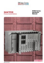
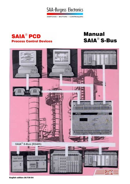
<strong>SAIA</strong> ® <strong>PCD</strong><br />
Process Control Devices<br />
<strong>Manual</strong><br />
<strong>SAIA</strong> ® S-<strong>Bus</strong><br />
English edition 26/739 E4
<strong>SAIA</strong>-Burgess Electronics Ltd.<br />
Bahnhofstrasse 18<br />
CH-3280 Murten (Switzerland)<br />
http;//www.saia-burgess.com<br />
BA: Electronic Controllers Telephone 026 / 672 72 72<br />
Telefax 026 / 672 74 99<br />
___________________________________________________________________________________________________________________________<br />
<strong>SAIA</strong>-Burgess Companies<br />
Switzerland<br />
<strong>SAIA</strong>-Burgess Electronics AG<br />
Freiburgstrasse 33<br />
CH-3280 Murten<br />
026 672 77 77, Fax 026 670 19 83<br />
France<br />
<strong>SAIA</strong>-Burgess Electronics Sàrl.<br />
10, Bld. Louise Michel<br />
F-92230 Gennevilliers<br />
01 46 88 07 70, Fax 01 46 88 07 99<br />
Germany<br />
<strong>SAIA</strong>-Burgess Electronics GmbH<br />
Daimlerstrasse 1k<br />
D-63303 Dreieich<br />
06103 89 060, Fax 06103 89 06 66<br />
Nederlands<br />
<strong>SAIA</strong>-Burgess Electronics B.V.<br />
Hanzeweg 12c<br />
NL-2803 MC Gouda<br />
0182 54 31 54, Fax 0182 54 31 51<br />
Austria<br />
<strong>SAIA</strong>-Burgess Electronics Ges.m.b.H.<br />
Schallmooser Hauptstrasse 38<br />
A-5020 Salzburg<br />
0662 88 49 10, Fax 0662 88 49 10 11<br />
Belgium<br />
<strong>SAIA</strong>-Burgess Electronics Belgium<br />
Avenue Roi Albert 1er, 50<br />
B-1780 Wemmel<br />
02 456 06 20, Fax 02 460 50 44<br />
Italy<br />
<strong>SAIA</strong>-Burgess Electronics S.r.l.<br />
Via Cadamosto 3<br />
I-20094 Corsico MI<br />
02 48 69 21, Fax 02 48 60 06 92<br />
Hungary<br />
<strong>SAIA</strong>-Burgess Electronics Automation Kft.<br />
Liget utca 1.<br />
H-2040 Budaörs<br />
23 501 170, Fax 23 501 180<br />
Representatives<br />
Great Britain<br />
Canham Controls Ltd.<br />
25 Fenlake <strong>Bus</strong>iness Centre, Fengate<br />
Peterborough PE1 5BQ UK<br />
01733 89 44 89, Fax 01733 89 44 88<br />
Portugal<br />
INFOCONTROL Electronica e Automatismo LDA.<br />
Praceta Cesário Verde, No 10 s/cv, Massamá<br />
P-2745 Queluz<br />
21 430 08 24, Fax 21 430 08 04<br />
Denmark<br />
Malthe Winje Automation AS<br />
Håndværkerbyen 57 B<br />
DK-2670 Greve<br />
70 20 52 01, Fax 70 20 52 02<br />
Spain<br />
Tecnosistemas Medioambientales, S.L.<br />
Poligono Industrial El Cabril, 9<br />
E-28864 Ajalvir, Madrid<br />
91 884 47 93, Fax 91 884 40 72<br />
Norway<br />
Malthe Winje Automasjon AS<br />
Haukelivn 48<br />
N-1415 Oppegård<br />
66 99 61 00, Fax 66 99 61 01<br />
Czech<br />
Republic<br />
ICS Industrie Control Service, s.r.o.<br />
Modranská 43<br />
CZ-14700 Praha 4<br />
2 44 06 22 79, Fax 2 44 46 08 57<br />
Sweden<br />
Malthe Winje Automation AB<br />
Truckvägen 14A<br />
S-194 52 Upplands Våsby<br />
08 795 59 10, Fax 08 795 59 20<br />
Poland<br />
SABUR Ltd.<br />
ul. Druzynowa 3A<br />
PL-02-590 Warszawa<br />
22 844 63 70, Fax 22 844 75 20<br />
Suomi/<br />
Finland<br />
ENERGEL OY<br />
Atomitie 1<br />
FIN-00370 Helsinki<br />
09 586 2066, Fax 09 586 2046<br />
Australia<br />
Siemens Building Technologies Pty. Ltd.<br />
Landis & Staefa Division<br />
411 Ferntree Gully Road<br />
AUS-Mount Waverley, 3149 Victoria<br />
3 9544 2322, Fax 3 9543 8106<br />
Argentina<br />
MURTEN S.r.l.<br />
Av. del Libertador 184, 4° “A”<br />
RA-1001 Buenos Aires<br />
054 11 4312 0172, Fax 054 11 4312 0172<br />
After sales service<br />
USA<br />
<strong>SAIA</strong>-Burgess Electronics Inc.<br />
1335 Barclay Boulevard<br />
Buffalo Grove, IL 60089, USA<br />
847 215 96 00, Fax 847 215 96 06<br />
___________________________________________________________________________________________________________________________<br />
Issue : 22.11.2000<br />
Subjet to change without notice
<strong>SAIA</strong> ® Process Control Devices<br />
<strong>Manual</strong><br />
<strong>SAIA</strong> ® S-BUS<br />
for the <strong>PCD</strong> family<br />
<strong>SAIA</strong>-Burgess Electronics Ltd. 1996 - 2000. All rights reserved<br />
Edition 26/739 E4 - 04.2000<br />
Subject to technical changes<br />
© <strong>SAIA</strong>-Burgess Electronics Ltd.
Updates<br />
<strong>Manual</strong> :<br />
<strong>SAIA</strong> S-<strong>Bus</strong> for the <strong>PCD</strong> family - Edition E4<br />
Date Chapter Page Description<br />
11.05.2000 6.6 6-8 / 6-9 Gateway master, enlarged table<br />
06.10.2000 3.12 3-53 SYSWR : Code 6000 (write EEPROM)<br />
© <strong>SAIA</strong>-Burgess Electronics Ltd.
<strong>Manual</strong> S-<strong>Bus</strong><br />
Contents<br />
Contents<br />
Page<br />
1. Introduction<br />
1.1 What is the <strong>SAIA</strong> S-<strong>Bus</strong> ? 1-1<br />
1.2 Typical Applications 1-3<br />
1.3 Characteristics 1-5<br />
1.4 The S-<strong>Bus</strong> protocol 1-7<br />
1.4.1 Application Layer 1-7<br />
1.4.2 Presentation Layer 1-7<br />
1.4.3 Network Layer 1-8<br />
1.4.4 Data Link Layer 1-10<br />
1.4.5 Physical Layer 1-12<br />
2. Installation<br />
2.1 Point to point connection 2-1<br />
2.2 S-<strong>Bus</strong> network 2-2<br />
3. Data Transfer Service<br />
3.1 Operating principle and application 3-1<br />
3.2 <strong>PCD</strong> instructions for S-<strong>Bus</strong> 3-7<br />
3.3 SASI Assign serial interface 3-8<br />
3.4 SRXM Receive data from a slave station 3-25<br />
3.4.1 Special functions 3-27<br />
3.4.2 Transfer of Data Blocks (Read) 3-28<br />
3.4.3 Practical application 3-31<br />
3.5 STXM Transmit data to a slave station 3-33<br />
3.5.1 Special functions 3-35<br />
3.5.2 Transfer of Data Blocks (Write) 3-36<br />
3.5.3 Practical application 3-38<br />
26/739 E4 (SB-00-E.DOC) © <strong>SAIA</strong>-Burgess Electronics Ltd. Page 1
Contents<br />
<strong>Manual</strong> S-<strong>Bus</strong><br />
Page<br />
3.6 SASII Assign serial interface indirect 3-40<br />
3.7 SRXMI Read data in indirect mode 3-41<br />
3.8 STXMI Transmit data in indirect mode 3-44<br />
3.9 SICL Input Control Line 3-46<br />
3.10 SOCL Output Control Line 3-47<br />
3.11 SYSRD System Read 3-49<br />
3.12 SYSWR System Write 3-52<br />
3.13 Communication via modem 3-55<br />
3.13.1 Multipoint modems and converters 3-56<br />
3.13.2 Modems for the Public Telephone Network 3-60<br />
3.14 Examples of user programs in IL 3-61<br />
3.14.1 Example 1 3-61<br />
3.14.2 Example 2 3-64<br />
3.15 Example of user programs in FUPLA 3-67<br />
4. Commissioning service<br />
4.1 Essential characteristics and applications 4-1<br />
4.2 Local programming and commissioning 4-3<br />
4.3 Configuration and assignment of an S-<strong>Bus</strong> PGU interface 4-5<br />
4.3.1 Memory modules with RAM components 4-5<br />
4.3.2 Memory modules with EPROM components 4-9<br />
4.4 Connection of the PG Unit via S-<strong>Bus</strong> 4-11<br />
Page 2 © <strong>SAIA</strong>-Burgess Electronics Ltd. (SB-00-E.DOC) 26/739 E4
<strong>Manual</strong> S-<strong>Bus</strong><br />
Contents<br />
Page<br />
5. Modems<br />
5.1 Transmission speeds 5-2<br />
5.2 Operating your modem 5-4<br />
5.2.1 The AT command set 5-5<br />
5.2.2 Important configuration parameters for the PG4<br />
and <strong>PCD</strong> modem 5-7<br />
5.2.3 Configuring the <strong>PCD</strong> Utilities for your modem 5-9<br />
5.2.4 <strong>PCD</strong> and modem 5-14<br />
5.2.5 Run sequence of modem in the <strong>PCD</strong> 5-16<br />
5.3 Connection via the Public Telephone Network 5-19<br />
5.3.1 Application diagram 5-19<br />
5.3.2 Configuring the <strong>PCD</strong> 5-21<br />
5.3.3 Configuring the PC (PG4) 5-23<br />
5.3.4 Making the connection 5-27<br />
5.3.5 Trouble shooting 5-30<br />
5.3.6 Ending the connection 5-31<br />
5.4 Modem + 5-32<br />
5.4.1 Diagnostics (SASI DIAG) 5-33<br />
5.4.2 SICL instruction 5-33<br />
5.4.3 UNDO/REDO a S-<strong>Bus</strong> PGU port (SASI OFF) 5-34<br />
5.5 Example of <strong>PCD</strong> program 5-39<br />
6. S-<strong>Bus</strong> Gateway<br />
6.1 Introduction 6-1<br />
6.2 Features of the Gateway 6-2<br />
6.3 Configuration of a Gateway Master Port (GMP) 6-3<br />
6.4 Configuration of the Gateway Slave Port 6-6<br />
6.4.1 S-<strong>Bus</strong>-PGU 6-6<br />
6.4.2 User SASI instruction 6-6<br />
6.5 Using STXM / SRXM in the Gateway station 6-7<br />
6.6 Setting Timeout in an S-<strong>Bus</strong> network 6-8<br />
6.7 Possible sources of errors 6-10<br />
26/739 E4 (SB-00-E.DOC) © <strong>SAIA</strong>-Burgess Electronics Ltd. Page 3
Contents<br />
<strong>Manual</strong> S-<strong>Bus</strong><br />
Page<br />
7. Using S-<strong>Bus</strong> with the PG3<br />
7.1 Station number definition 7-2<br />
7.2 Configuration and assignment of an S-<strong>Bus</strong> PGU interface 7-4<br />
7.2.1 Memory modules with RAM components 7-4<br />
7.2.2 Memory modules with EPROM components 7-7<br />
7.3 Connection of the PG Unit via S-<strong>Bus</strong> 7-8<br />
7.4 Configuring the <strong>PCD</strong> Utilities for your modem 7-9<br />
7.5 Connection via the Public Telephone Network 7-14<br />
7.5.1 Application diagram 7-14<br />
7.5.2 Configuring the <strong>PCD</strong> 7-15<br />
7.5.3 Configuring the PC (PG3) 7-17<br />
7.5.4 Making the connection 7-19<br />
7.5.5 Trouble shooting 7-20<br />
7.5.6 Ending the connection 7-21<br />
7.6 Example of <strong>PCD</strong> program (with modem) 7-22<br />
7.7 Configuration of a Gateway Master Port (GMP) 7-28<br />
8. Appendixes<br />
A Compatibility for using S-<strong>Bus</strong> at 38.4 Kbps 8-1<br />
B S-<strong>Bus</strong> PGU interfaces and cables 8-2<br />
C Firmware and software compatibility 8-7<br />
Page 4 © <strong>SAIA</strong>-Burgess Electronics Ltd. (SB-00-E.DOC) 26/739 E4
<strong>Manual</strong> S-<strong>Bus</strong><br />
Contents<br />
! Please note :<br />
A number of detailed manuals are available to aid installation and operation<br />
of the <strong>SAIA</strong> <strong>PCD</strong>. These are for use by technically qualified staff,<br />
who may also have successfully completed one of our "workshops".<br />
To obtain the best performance from your <strong>SAIA</strong> <strong>PCD</strong>, closely follow the<br />
guidelines for assembly, wiring, programming and commissioning given in<br />
these manuals. In this way, you will also become one of the many enthusiastic<br />
<strong>SAIA</strong> <strong>PCD</strong> users.<br />
If you have any technical suggestions or recommendations for improvements<br />
to the manuals, please let us know. A form is provided on the last<br />
page of this manual for your comments.<br />
Summary<br />
<strong>PCD</strong>1/2 series <strong>PCD</strong>4 series <strong>PCD</strong>6 series<br />
Hardw are<br />
<strong>PCD</strong>1<br />
<strong>PCD</strong>2<br />
Serie xx7<br />
Hardware<br />
<strong>PCD</strong>4<br />
<strong>PCD</strong>4.H1..<br />
*)<br />
Hardware<br />
<strong>PCD</strong>6<br />
<strong>PCD</strong>2.M250<br />
General<br />
<strong>Manual</strong>s<br />
<strong>PCD</strong>2.H110<br />
<strong>PCD</strong>2.H150<br />
<strong>PCD</strong>2.H210<br />
<strong>PCD</strong>2.H31x<br />
<strong>PCD</strong>4.H2..<br />
<strong>PCD</strong>4.H3..<br />
*)<br />
<strong>PCD</strong>4.H4..<br />
*)<br />
*) Adapter module 4'717'4828'0<br />
allows H modules to be used<br />
with the <strong>PCD</strong>6.<br />
User's<br />
Guide<br />
Reference<br />
Guide<br />
(PG3)<br />
<strong>PCD</strong>8.P1..<br />
<strong>PCD</strong>7.D1..<br />
<strong>PCD</strong>7.D2..<br />
<strong>PCD</strong>7.D7..<br />
- S-<strong>Bus</strong><br />
- LON<br />
- PROFIBUS<br />
Installation<br />
Components<br />
for RS 485-<br />
Networks<br />
- PG4<br />
- Modem<br />
FUPLA/<br />
KOPLA<br />
function<br />
families<br />
26/739 E4 (SB-00-E.DOC) © <strong>SAIA</strong>-Burgess Electronics Ltd. Page 5
Contents<br />
<strong>Manual</strong> S-<strong>Bus</strong><br />
Reliability and safety of electronic controllers<br />
<strong>SAIA</strong>-Burgess Electronics Ltd. is a company which devotes the greatest<br />
care to the design, development and manufacture of its products:<br />
• state-of-the-art technology<br />
• compliance with standards<br />
• ISO 9001 certification<br />
• international approvals: e.g. Germanischer Lloyd,<br />
United Laboratories (UL), Det Norske Veritas, CE mark ...<br />
• choice of high-quality componentry<br />
• quality control checks at various stages of production<br />
• in-circuit tests<br />
• run-in (burn-in at 85°C for 48h)<br />
Despite every care, the excellent quality which results from this does<br />
have its limits. It is therefore necessary, for example, to reckon with the<br />
natural failure of components. For this reason <strong>SAIA</strong>-Burgess Electronics<br />
Ltd. provides a guarantee according to the "General terms and conditions<br />
of supply".<br />
The plant engineer must in turn also contribute his share to the reliable<br />
operation of an installation. He is therefore responsible for ensuring that<br />
controller use conforms to the technical data and that no excessive<br />
stresses are placed on it, e.g. with regard to temperature ranges, overvoltages<br />
and noise fields or mechanical stresses.<br />
In addition, the plant engineer is also responsible for ensuring that a<br />
faulty product in no case leads to personal injury or even death, nor to<br />
the damage or destruction of property. The relevant safety regulations<br />
should always be observed. Dangerous faults must be recognized by additional<br />
measures and any consequences prevented. For example, outputs<br />
which are important for safety should lead back to inputs and be monitored<br />
from software. Consistent use should be made of the diagnostic<br />
elements of the <strong>PCD</strong>, such as the watchdog, exception organization<br />
blocks (XOB) and test or diagnostic instructions.<br />
If all these points are taken into consideration, the <strong>SAIA</strong> <strong>PCD</strong> will provide<br />
you with a modern, safe programmable controller to control, regulate<br />
and monitor your installation with reliability for many years.<br />
Page 6 © <strong>SAIA</strong>-Burgess Electronics Ltd. (SB-00-E.DOC) 26/739 E4
<strong>Manual</strong> S-<strong>Bus</strong><br />
Introduction<br />
1. Introduction<br />
1.1 What is the <strong>SAIA</strong> S-<strong>Bus</strong> ?<br />
S-<strong>Bus</strong> is the name of an efficient communication protocol for the <strong>SAIA</strong> ®<br />
<strong>PCD</strong> generation of controllers. It can be used for both point-to-point<br />
communications and within a local master/slave network.<br />
For point-to-point communications, any of the <strong>PCD</strong>'s serial interfaces can<br />
be used.<br />
At the physical level, an S-<strong>Bus</strong> network uses the RS 485 standard, via<br />
two-core twisted and shielded cable. S-<strong>Bus</strong> can be used as a simple, economic<br />
means of networking up to 255 <strong>PCD</strong> systems, connected to up to 8<br />
segments, each containing up to 32 stations.<br />
S-<strong>Bus</strong> has the following major characteristics :<br />
• Ease of handling (installation, commissioning and user programming)<br />
• Cost effective, since the S-<strong>Bus</strong> protocol is already built into every<br />
<strong>PCD</strong> processor. This means that no additional dedicated communications<br />
processor is required.<br />
• Fail-safe data transfer, using CRC-16 error detection.<br />
• High data transfer rate, due to the efficient binary protocol with<br />
transmission speed up to 38.4 kbps.<br />
• Support for remote data access and diagnostics via a modem on<br />
leased or dial-up lines.<br />
• Drivers are available for supervisory control systems such as Wizcon,<br />
InTouch, FactoryLink, Fix D-Macs and Genesis.<br />
• With application level 2 (commissioning service) the programming<br />
unit has access to all slave stations on the network. This means that<br />
any slave station connected to the network can be controlled by the<br />
programming unit from a central point (e.g. by the debugger).<br />
• Multi-master possibility by using the S-<strong>Bus</strong> Gateway<br />
• Access possible to all media in slave.<br />
26/739 E4 (SB-10-E.DOC) © <strong>SAIA</strong>-Burgess Electronics Ltd. Page 1-1
Introduction<br />
<strong>Manual</strong> S-<strong>Bus</strong><br />
Glossary<br />
P8 or P800 also called D mode :<br />
original protocol used for the programming unit.<br />
PGU<br />
PLM<br />
PSTN<br />
SCADA<br />
SCS<br />
GSM<br />
ISDN<br />
ProGramming Unit.<br />
This term designates the programming console, but also<br />
by extension the port where the console must be connected.<br />
The PGU designates also the protocol used by the<br />
programming console.<br />
Public Line Modem.<br />
Public Switched Telephone Network.<br />
Supervisory Control and Data Acquisition<br />
Supervisory Control Systems<br />
Global System for Mobile communication<br />
Integrated Services Digital Network<br />
Page 1-2 © <strong>SAIA</strong>-Burgess Electronics Ltd. (SB-10-E.DOC) 26/739 E4
<strong>Manual</strong> S-<strong>Bus</strong><br />
Introduction<br />
1.2 Typical Applications<br />
The S-<strong>Bus</strong> protocol was developed specifically for the RS 485 S-<strong>Bus</strong><br />
network. However, it can also be used with the other serial interfaces for<br />
point-to-point connections.<br />
S-<strong>Bus</strong> Protocol<br />
Point to Point<br />
Connection<br />
RS232, RS422<br />
Master<br />
or 20 mA CL<br />
<strong>PCD</strong> 1/2/4/6<br />
Programming Unit or<br />
Control System<br />
Slave<br />
<strong>PCD</strong> 1/2/4/6<br />
Applications<br />
S-<strong>Bus</strong> Network<br />
Master<br />
<strong>PCD</strong> 1/2/4/6<br />
Programming Unit or<br />
Control System<br />
Slave Slave Slave<br />
<strong>PCD</strong> 1/2/4/6<br />
The master station can be a <strong>PCD</strong>2, <strong>PCD</strong>4, <strong>PCD</strong>6 (also <strong>PCD</strong>1 from FW<br />
version V005), the programming unit or any non-<strong>SAIA</strong> system. Several<br />
supervisory control systems (e.g. Wizcon, FactoryLink, In Touch, Fix<br />
DMACS, …) provide driver for the S-<strong>Bus</strong> protocol.<br />
Without repeaters it is possible to connect up to 32 stations over a maximum<br />
distance of 1200m in this way.<br />
Network with "Multipoint" modem to bridge large distances using leased<br />
or private telephone lines. The RS 232 interface is used in S-<strong>Bus</strong> mode to<br />
connect between the modem and the <strong>PCD</strong>.<br />
Master<br />
<strong>PCD</strong> 1/2/4/6<br />
Programming Unit or<br />
Control System<br />
Leased line<br />
Modem<br />
Modem Modem Modem<br />
Slave Slave Slave<br />
<strong>PCD</strong> 1/2/4/6<br />
26/739 E4 (SB-10-E.DOC) © <strong>SAIA</strong>-Burgess Electronics Ltd. Page 1-3
Introduction<br />
<strong>Manual</strong> S-<strong>Bus</strong><br />
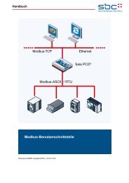
The S-<strong>Bus</strong> protocol can also be used with modems; allowing the <strong>SAIA</strong><br />
<strong>PCD</strong>s to communicate through the Public Telephone Network.<br />
This type of connection can be used for remote supervision and/or remote<br />
programming and commissioning. Possible telephone networks are:<br />
analogue, digital (ISDN), radio (GSM), etc.<br />
Master<br />
Modem<br />
<strong>PCD</strong> 1/2/4/6<br />
Programming Unit or<br />
Control System<br />
Public Phone<br />
Network<br />
Modem<br />
Modem<br />
Slave<br />
<strong>PCD</strong> 1/2/4/6<br />
Modem<br />
Slave<br />
Slave<br />
Even if the S-<strong>Bus</strong> network is a single master / multiple slaves; a feature<br />
called the “Gateway” allows other masters connected to the first one to<br />
communicate with all the slaves present on the network.<br />
Master<br />
Master<br />
<strong>PCD</strong> 1/2/4/6<br />
Programming Unit or<br />
Control System<br />
Gateway<br />
Master <strong>PCD</strong> 2 / 4 / 6<br />
Slave Slave Slave<br />
<strong>PCD</strong> 1/2/4/6<br />
Page 1-4 © <strong>SAIA</strong>-Burgess Electronics Ltd. (SB-10-E.DOC) 26/739 E4
<strong>Manual</strong> S-<strong>Bus</strong><br />
Introduction<br />
1.3 Characteristics<br />
Network<br />
Master/slave<br />
bus with single master and several slaves<br />
(Single Client / Multiple Servers)<br />
Physical interface RS 485<br />
<strong>Bus</strong> line<br />
twisted two-core, shielded,<br />
line section min. 2 ∗ 0.5 mm2<br />
length max. 1200 m per segment<br />
Number of stations max. 32 per segment, total max. 255<br />
Number of segments<br />
max. 8, connected together via<br />
repeater <strong>PCD</strong>7.T100<br />
Point-to-point connection<br />
Interfaces<br />
RS 232, RS 422, 20mA CL<br />
Electrical characteristics of interfaces<br />
See hardware manuals<br />
<strong>PCD</strong>1 - <strong>PCD</strong>2, <strong>PCD</strong>4 and <strong>PCD</strong>6.<br />
S-<strong>Bus</strong> protocol<br />
Baud rate<br />
Start bit 1<br />
Character length<br />
from 110 to 38'400 bit/s<br />
8 bits<br />
Parity bit mode SM2/SS2 : no parity<br />
mode SM1/SS1 : parity 1 / 0<br />
mode SM0/SS0 : no parity<br />
Stop bit 1<br />
Data transfer rate standard : 167 registers/s (at 9600 bps)<br />
maximum : 265 registers/s (at 19200 bps)<br />
Reaction times for 1 to 8 in-/outputs or flags : 18 ms<br />
transmission at 128 in-/outputs or flags : 35 ms<br />
9600 bps of 1 register : 20 ms<br />
32 registers 125 ms<br />
Error detection<br />
CRC-16<br />
26/739 E4 (SB-10-E.DOC) © <strong>SAIA</strong>-Burgess Electronics Ltd. Page 1-5
Introduction<br />
<strong>Manual</strong> S-<strong>Bus</strong><br />
Programming<br />
The following <strong>PCD</strong> instructions are provided :<br />
• Initialise serial interfaces instructions<br />
• Instructions for data exchange<br />
• Control line handling instructions<br />
• System parameters read & write instructions<br />
Supervisory control systems<br />
S-<strong>Bus</strong> drivers are available for the following systems :<br />
• Wizcon<br />
• Genesis<br />
• FactoryLink<br />
• InTouch<br />
• Fix D-Macs<br />
• Windows DDE<br />
For implementation of the S-<strong>Bus</strong> protocol in a non-<strong>SAIA</strong> system, <strong>SAIA</strong>-<br />
Burgess Electronics Ltd. provides software libraries for Windows DLL as<br />
well as in the C programming language.<br />
Page 1-6 © <strong>SAIA</strong>-Burgess Electronics Ltd. (SB-10-E.DOC) 26/739 E4
<strong>Manual</strong> S-<strong>Bus</strong><br />
Introduction<br />
1.4 The S-<strong>Bus</strong> protocol<br />
OSI model applied to <strong>SAIA</strong> S-<strong>Bus</strong>:<br />
The following diagram shows the implementation of the layers in the<br />
<strong>SAIA</strong>-<strong>Bus</strong> protocol<br />
Application Layer <strong>SAIA</strong> S-<strong>Bus</strong> Reduced & Full Protocol<br />
Presentation Layer Telegrams 0 .. 255<br />
Session Layer not used<br />
Transport Layer not used<br />
Network Layer Forced parity mechanism<br />
Data Link Layer ACK/NAK mechanism<br />
Byte synchronisation + CRC 16 Error check<br />
Physical Layer RS485, RS 232, 20mA CL, etc.<br />
1.4.1 Application Layer<br />
Data transfer service (level 1)<br />
A subset of the S-<strong>Bus</strong> protocol (also called Reduced protocol). The master<br />
station can only read and write <strong>PCD</strong> data in a slave station, and the<br />
slave station's status can be read.<br />
<strong>PCD</strong> data : Inputs, Outputs, Flags, Registers, Timers, Counters, Data<br />
Blocks and the hardware clock.<br />
Commissioning service (level 2)<br />
This level <strong>support</strong>s the entire S-<strong>Bus</strong> protocol (Full S-<strong>Bus</strong>), the programming<br />
unit (PGU) can be used to control each slave station on the network.<br />
The commissioning service is also called S-<strong>Bus</strong> PGU. Access via<br />
the public telephone system is also <strong>support</strong>ed: slave station programming<br />
and commissioning can therefore be done from a central point.<br />
1.4.2 Presentation Layer<br />
Most of the telegram are of a fixed length and so there is no requirement<br />
for a special end of telegram character. Those telegrams that are not of<br />
fixed length have a count byte immediately following the command code<br />
to indicate the length of the telegram. There is no need of a count byte in<br />
the response telegram as the Client will already know the length of the<br />
telegram that he is expecting.<br />
A telegram can have an absolute maximum length of 32 registers/ timers/counters<br />
or 128 flags/inputs/outputs when in run. Some special telegrams<br />
can have more bytes than this but these telegrams cannot be used<br />
when the CPU is in run. For instance, to optimise the downloading of a<br />
program up to 64 program lines can be transferred at a time which gives a<br />
maximum telegram length of 263 bytes.<br />
26/739 E4 (SB-10-E.DOC) © <strong>SAIA</strong>-Burgess Electronics Ltd. Page 1-7
Introduction<br />
<strong>Manual</strong> S-<strong>Bus</strong><br />
Example of an S-<strong>Bus</strong> telegram<br />
Write Register 100 with the value 12345 (Dec) to station 10 in the <strong>SAIA</strong>-<br />
<strong>Bus</strong> network. The telegram will look like so :<br />
<br />
Two byte of CRC-16 code<br />
Value 12345 (Dec) in hexadecimal (4 bytes)<br />
Absolute address of register (2 bytes)<br />
Count of number of bytes (without the CRC)<br />
Command code<br />
Address of station<br />
1.4.3 Network Layer<br />
The network layer service is very simple and takes advantage of the multidrop<br />
feature of the DUART used in the <strong>PCD</strong> family. This multidrop<br />
mode eliminates the need for special start characters in each telegram.<br />
This mode <strong>support</strong>s two different types of character, an address character<br />
and a data character. The difference between the two is that for an address<br />
character the parity bit is forced to 1 and for a data character the<br />
parity bit is forced to 0.<br />
A telegram consists of an address character followed by a number of data<br />
characters targeted for a particular slave station. When any address character<br />
is detected in the data stream the slave station compares its address<br />
to the address character received before deciding whether to receive the<br />
data characters in the telegram. Slave stations which are not addressed<br />
continue monitoring the data stream for the next address character.<br />
The address 255 (dec) is to be reserved for broadcast messages. No response<br />
is expected after transmission of a broadcast message. This mode<br />
of operation is called the parity mechanism.<br />
Because that most of the public line modems do not <strong>support</strong> 9 bit characters<br />
as used for the parity mechanism and also the Break character<br />
used to indicate the beginning of every telegram; another mode called<br />
“Data Mode” is then used.<br />
Page 1-8 © <strong>SAIA</strong>-Burgess Electronics Ltd. (SB-10-E.DOC) 26/739 E4
<strong>Manual</strong> S-<strong>Bus</strong><br />
Introduction<br />
1.4.3.1 Data Mode (SM2/SS2)<br />
In data mode each telegram begins with a special FS character. (FS =<br />
frame synchronisation). This FS character always has the value B5 and<br />
does not appear in the telegram, except in the telegram header. The second<br />
character transmitted in data mode is telegram information. This<br />
telegram information is called the AT character and may contain, for example,<br />
the following information: The current telegram is a request telegram,<br />
a reply telegram, etc.<br />
S-<strong>Bus</strong> Telegram (principle) :<br />
0 10110101 1 0 XXXXXXXX 1<br />
0 XXXXXXXX 1 0 XXXXXXXX 1<br />
FS char<br />
AT char<br />
Slave addr<br />
Data char<br />
1.4.3.2 Parity Mode (SM1/SS1)<br />
The parity bit used in so called multidrop mode to indicate the type of<br />
current character as follows : 1 Address character<br />
0 Data character<br />
S-<strong>Bus</strong> Telegram (principle) :<br />
0 XXXXXXXX 1 1 0 XXXXXXXX 0 1 0 XXXXXXXX 0 1 0 XXXXXXXX 0 1<br />
Slave Address<br />
Data characters<br />
1.4.3.3 Break Mode (SM0/SS0)<br />
The BREAK character is a special character: the serial data is low for the<br />
entire character including the stop bit.<br />
S-<strong>Bus</strong> Telegram (principle) :<br />
0 00000000 0 0 XXXXXXXX 1<br />
0 XXXXXXXX 1 0 XXXXXXXX 1<br />
Break char<br />
Slave Address<br />
Data characters<br />
The Break character can be detected by the remote <strong>PCD</strong>; it indicates the<br />
start of an S-<strong>Bus</strong> telegram. The S-<strong>Bus</strong> driver on the remote <strong>PCD</strong> will always<br />
read the character following the Break character as the address<br />
character and the appended character as data characters of current telegram.<br />
26/739 E4 (SB-10-E.DOC) © <strong>SAIA</strong>-Burgess Electronics Ltd. Page 1-9
Introduction<br />
<strong>Manual</strong> S-<strong>Bus</strong><br />
1.4.4 Data Link Layer<br />
The Upper Sub-layer manages the point to point communication between<br />
stations on the network. If a telegram is lost or corrupted then this layer<br />
will manage the retransmission of this telegram. The functionality of this<br />
level can be seen in the following diagrams.<br />
If a corrupted telegram is detected then there is no response and the client<br />
will time-out up to three times before informing the upper layers that<br />
there has been a transmission failure. The time-out will be a function of<br />
the Baud rate.<br />
Transmission of a command telegram<br />
This shows the successful transmission of a telegram.<br />
Client<br />
Server<br />
request<br />
ACK<br />
next request<br />
action<br />
If a corrupted telegram is received at the server and the client receives no<br />
response. The telegram will then be retransmitted after the client has<br />
timed out.<br />
A message is transmitted a total of three times, i.e. there will be two retries.<br />
Client<br />
time-out<br />
request<br />
request<br />
NAK<br />
request<br />
ACK<br />
error detected by<br />
the CRC-16<br />
Uncorrupted but<br />
Illegal telegram<br />
Valid telegram<br />
positive response<br />
Page 1-10 © <strong>SAIA</strong>-Burgess Electronics Ltd. (SB-10-E.DOC) 26/739 E4
<strong>Manual</strong> S-<strong>Bus</strong><br />
Introduction<br />
Invocation of response messages<br />
Upon reception of the read telegram the server will transmit the response directly.<br />
Any response which appears on the network must be for the client, so<br />
there is no need for a special start of telegram character or address character<br />
for the response.<br />
This example shows the successful execution of a read response telegram.<br />
Client<br />
request<br />
response<br />
next request<br />
Server<br />
reception<br />
Half-Duplex Protocol<br />
Only one station can be master in a network and so only a half duplex<br />
protocol is <strong>support</strong>ed. This means that there is never any danger of<br />
deadlock of contending clients.<br />
Lower Sub-layer<br />
The main task of this layer is to manage the CRC-16 error checking code.<br />
This type of error checking is used since this protocol uses no form of<br />
parity checking on individual bytes.<br />
The CRC-16 error checking algorithm uses the polynomial:<br />
X^16 + X^12 + X^5 + 1 = 1021 Hex<br />
This is the standard CCITT CRC (Reference CCITT V-41).<br />
26/739 E4 (SB-10-E.DOC) © <strong>SAIA</strong>-Burgess Electronics Ltd. Page 1-11
Introduction<br />
<strong>Manual</strong> S-<strong>Bus</strong><br />
1.4.5 Physical Layer<br />
<strong>SAIA</strong>-<strong>Bus</strong> will run on all the types of communications ports of the <strong>PCD</strong><br />
family.<br />
The <strong>SAIA</strong> S-<strong>Bus</strong> is designed principally to run over an RS485 Multidrop<br />
network of one client and a maximum of 255 servers using an S-<strong>Bus</strong> repeater.<br />
The <strong>SAIA</strong> S-<strong>Bus</strong> can also run over an RS-232 serial interface and via<br />
modems.<br />
Page 1-12 © <strong>SAIA</strong>-Burgess Electronics Ltd. (SB-10-E.DOC) 26/739 E4
<strong>Manual</strong> S-<strong>Bus</strong><br />
Installation<br />
2. Installation<br />
2.1 Point to point connection<br />
In principle, any type of interface can be assigned in S-<strong>Bus</strong> mode. Since,<br />
as a rule, the creation of a point-point connection causes no installation<br />
problems, further details are not given here.<br />
A comprehensive description of pin allocation and data on the various<br />
interface types can be found in the <strong>PCD</strong>1 - <strong>PCD</strong>2, <strong>PCD</strong>4 and <strong>PCD</strong>6<br />
hardware manuals.<br />
For using S-<strong>Bus</strong> in RS232 on port 0 on a <strong>PCD</strong>2, a special handling must<br />
be done after the serial line has been assigned (see the SOCL instruction<br />
on chapter 3.10).<br />
26/739 E4 (SB-20-E.DOC) © <strong>SAIA</strong>-Burgess Electronics Ltd. Page 2-1
Installation<br />
<strong>Manual</strong> S-<strong>Bus</strong><br />
2.2 S-<strong>Bus</strong> network<br />
For installation of the S-<strong>Bus</strong> network, modules are required with the<br />
RS485 interface.<br />
Modules with RS485 interface :<br />
• <strong>PCD</strong>1.M110 with interface n° 1 (RS485)<br />
• <strong>PCD</strong>1.M120/M130 with <strong>PCD</strong>7.F110/F150 interface n° 1<br />
(RS422/485)<br />
• <strong>PCD</strong>2.M110/M120 with interface n° 0 (RS485) or<br />
or M150<br />
with F-modules <strong>PCD</strong>7.F110/F150<br />
interface n° 1 (RS422/485) or<br />
with <strong>PCD</strong>2.F5xx interface n° 3 (RS422/485)<br />
• <strong>PCD</strong>2.M250 with interface n° 0 (RS485) or<br />
(resp. M220) with F-modules <strong>PCD</strong>7.F110/F150<br />
interface n° 1 (RS422/485) or<br />
with <strong>PCD</strong>2.F5xx interface n° 3 (RS422/485)<br />
• <strong>PCD</strong>4.C130 bus module (interface n° 1)<br />
with processor modules <strong>PCD</strong>4.M12x, M14x,<br />
M240, M340 or M44x<br />
• <strong>PCD</strong>4.C340 bus module with <strong>PCD</strong>7.F110/F150<br />
with processor modules <strong>PCD</strong>4.M12x, M14x,<br />
M240, M340 or M44x<br />
• <strong>PCD</strong>6.M540 single processor module (interface n° 1)<br />
• <strong>PCD</strong>6.M220 communications processor module<br />
(interface n° 0)<br />
• <strong>PCD</strong>6.M260 communications processor module<br />
(interfaces n° 0, 1, 2, 3)<br />
• <strong>PCD</strong>6.M300 communications processor module with<br />
F-modules <strong>PCD</strong>7.F110/F150<br />
(interfaces n° 0, 1, 2, 3)<br />
Consult the appropriate <strong>PCD</strong> hardware manual to obtain all information<br />
about these modules and how to connect them.<br />
Page 2-2 © <strong>SAIA</strong>-Burgess Electronics Ltd. (SB-20-E.DOC) 26/739 E4
+<br />
+<br />
+<br />
<strong>Manual</strong> S-<strong>Bus</strong><br />
Installation<br />
To guarantee in a rough and noisy industrial environment an error free<br />
operation of the RS485 network it is recommended to use the special installation<br />
components for RS485 networks.<br />
The following components are available :<br />
Termination box <strong>PCD</strong>7.T160<br />
This very simple module is used to terminate the network correctly and to<br />
apply bias voltage to the signal lines with an electrically isolated supply<br />
and the correct off-load potential.<br />
Converter <strong>PCD</strong>7.T120 (RS232/485) and <strong>PCD</strong>7.T140 (RS422/485)<br />
The converters enable electrically isolated conversion from the RS232 or<br />
RS422 of a remote station to the RS485 2-wire bus and vice versa.<br />
Repeater <strong>PCD</strong>7.T100<br />
The repeater is used not only for the electrical isolation of individual line<br />
sections from each other, but also to reprocess signals travelling longer<br />
distances.<br />
A detailed description of these components and general information for<br />
the installation and commissioning of an RS485 network can be found in<br />
the manual "Installation components for RS 485 networks".<br />
In this manual the installation of an S-<strong>Bus</strong> network is described without<br />
the use of the special installation components.<br />
<strong>PCD</strong>7.T160<br />
<strong>PCD</strong>7.T100<br />
RS 485 Segment 1 Segment 2<br />
+<br />
RS 485<br />
<strong>PCD</strong>7.T160<br />
RS 232<br />
<strong>PCD</strong>7.T120<br />
1 2 31<br />
<strong>PCD</strong>7.T120<br />
<strong>PCD</strong>7.T100<br />
RS 232<br />
1 2 30<br />
<strong>PCD</strong>7.T160<br />
RS 485 Segment 3 +<br />
<strong>PCD</strong>7.T160<br />
<strong>PCD</strong>7.T100<br />
RS 422<br />
<strong>PCD</strong>7.T140<br />
1 2 30<br />
<strong>PCD</strong>7.T160<br />
RS 485 Segment 4<br />
+<br />
<strong>PCD</strong>7.T160<br />
RS 232<br />
<strong>PCD</strong>7.T120<br />
1 2 31<br />
26/739 E4 (SB-20-E.DOC) © <strong>SAIA</strong>-Burgess Electronics Ltd. Page 2-3
Installation<br />
<strong>Manual</strong> S-<strong>Bus</strong><br />
Connection and placement of RS485 bus line<br />
To suppress interference and avoid reflections, pull-up/down line termination<br />
resistors must be provided both at the start and end of the bus<br />
line. These resistors are incorporated in all processor and bus modules<br />
and they can be switched on or connected according to choice.<br />
First Station Middle Stations End station<br />
+5V<br />
/RX RX<br />
/TX TX<br />
/RX RX<br />
/TX TX<br />
/RX RX<br />
/TX TX<br />
/RX RX<br />
/TX TX<br />
+5V<br />
Pull up<br />
330 Ohm<br />
Pull up<br />
330 Ohm<br />
Termination<br />
resistor<br />
RS 485<br />
(S-<strong>Bus</strong>)<br />
Termination<br />
resistor<br />
Pull down<br />
330 Ohm<br />
Segment: 1200m max<br />
max. 32 Stations<br />
Pull down<br />
330 Ohm<br />
When using the internal resistors of the processor or bus modules to terminate<br />
the lines, these stations can not be powered down otherwise the<br />
communication over the network is no more possible.<br />
If the network must still continue to work when the first and end stations<br />
are not powered, you must use <strong>PCD</strong>7.T160 termination boxes.<br />
The following points demand special attention :<br />
• When making the bus cable, strict attention is necessary not to mix up<br />
the data lines - "RX-TX" must therefore always run to "RX-TX" and<br />
"/RX-/TX" to "/RX-/TX".<br />
The denominations “RX-TX” and “/RX-/TX”are not always used :<br />
RX D –RX<br />
/RX /D +RX<br />
TX D –TX<br />
/TX /D +TX<br />
Page 2-4 © <strong>SAIA</strong>-Burgess Electronics Ltd. (SB-20-E.DOC) 26/739 E4
<strong>Manual</strong> S-<strong>Bus</strong><br />
Installation<br />
• Care should also be taken that the bus line remains continuously connected,<br />
even when one or more plugs are pulled out.<br />
• Spur cables (stubs) should not exceed 0.5 m.<br />
• Use stranded cable of at least 0.5 mm 2 , with 2 cores, twisted and<br />
shielded.<br />
Signal levels of the RS485 interface<br />
Signal type Logical state Polarity<br />
Data signal 0 (space) RX-TX positive to /RX-/TX<br />
1 (mark) /RX-/TX positive to RX-TX<br />
no driver active<br />
Mark<br />
Space<br />
5V<br />
= Mark<br />
e.g. start bit<br />
2.5V<br />
4V<br />
3V<br />
2V<br />
/TX<br />
TX<br />
VOZ<br />
VOH<br />
VOL<br />
1V<br />
0V<br />
VOZ = 0.9V min... 1.7V max (no driver active) *)<br />
VOH = 2V min (with load) ... 5V max (without load)<br />
VOZ = -2V ... -5V<br />
*) dependent of the Pull up, Termination and Pull down resistors.<br />
26/739 E4 (SB-20-E.DOC) © <strong>SAIA</strong>-Burgess Electronics Ltd. Page 2-5
Installation<br />
<strong>Manual</strong> S-<strong>Bus</strong><br />
Grounding of an RS485 bus line<br />
The cable's screening must always be connected at both ends, to produce<br />
a continuous, solid earth line, and so reduces potential differences to a<br />
minimum.<br />
First station Middle stations End station<br />
+5V +5V<br />
It is recommended that the RS485 cable is not laid in direct proximity to<br />
motor cables which may be produce interference, unless these cables are<br />
also well screened.<br />
Page 2-6 © <strong>SAIA</strong>-Burgess Electronics Ltd. (SB-20-E.DOC) 26/739 E4
<strong>Manual</strong> S-<strong>Bus</strong><br />
Data Transfer Service<br />
3. Data Transfer Service<br />
3.1 Operating principle and application<br />
Application level 1 (Reduced Protocol) enables <strong>PCD</strong> data to be exchanged<br />
via the S-<strong>Bus</strong> network or a point to point connection.<br />
The master station can be a <strong>PCD</strong>2, <strong>PCD</strong>4, <strong>PCD</strong>6 or any other non-<strong>SAIA</strong><br />
system (e.g. a supervisory control system such as Wizcon, Factory Link,<br />
etc.) which has a driver for the S-<strong>Bus</strong> protocol.<br />
All communication is controlled from the master station. The user program<br />
in the master station defines which data from a connected slave<br />
station are to be read or written. From the user's point of view, the behaviour<br />
of the slave station in this is passive. Communication is run<br />
automatically in the background by the CPU firmware. For the slave station,<br />
the user program only initialises the interface.<br />
<strong>PCD</strong> interfaces are assigned for the master station in SM2, SM1 or SM0<br />
mode (S-<strong>Bus</strong> master) and for the slave station in SS2, SS1 or SS0 mode<br />
(S-<strong>Bus</strong> slave).<br />
Station number definition<br />
Each slave station is allocated a number, so that it can be addressed from<br />
the master station. This number is stored in the user program's "header" in<br />
the memory module of a slave station<br />
The station number is stored differently, depending on the memory modules<br />
used.<br />
The main difference is that, when RAM memory modules are used, the<br />
number of the slave station is stored online in the <strong>PCD</strong>.<br />
However, if an EPROM memory module is used, slave number definition<br />
occurs offline, i.e. an EPROM is programmed with the slave number and<br />
the user program and is put in the <strong>PCD</strong> later.<br />
26/739 E4 (SB-31-E.DOC) © <strong>SAIA</strong>-Burgess Electronics Ltd. Page 3-1
Data Transfer Service<br />
<strong>Manual</strong> S-<strong>Bus</strong><br />
Station number definition when using memory modules with RAM<br />
1. Connect the programming unit to the "PGU" programming interface<br />
on the <strong>PCD</strong>.<br />
2. Start PG4 Project Manager.<br />
3. Press the "Online Configurator" button on the toolbar.<br />
The online configurator can then be seen:<br />
Page 3-2 © <strong>SAIA</strong>-Burgess Electronics Ltd. (SB-31-E.DOC) 26/739 E4
<strong>Manual</strong> S-<strong>Bus</strong><br />
Data Transfer Service<br />
4. Press the 'S-<strong>Bus</strong>' button:<br />
5. Select S-<strong>Bus</strong> Support and press the 'S-<strong>Bus</strong>' button:<br />
6. Enter the required station number<br />
All other parameters are not relevant at S-<strong>Bus</strong> Level 1, when neither a<br />
modem nor a repeater is being used.<br />
Exit the entry window by pressing the OK button.<br />
The following window must also be exited by pressing the OK button.<br />
26/739 E4 (SB-31-E.DOC) © <strong>SAIA</strong>-Burgess Electronics Ltd. Page 3-3
Data Transfer Service<br />
<strong>Manual</strong> S-<strong>Bus</strong><br />
The following warning can be confirmed with the YES button<br />
This will download the configuration that has been set to the<br />
controller.<br />
The number assigned can be viewed in the "Online Configurator"<br />
window.<br />
Page 3-4 © <strong>SAIA</strong>-Burgess Electronics Ltd. (SB-31-E.DOC) 26/739 E4
<strong>Manual</strong> S-<strong>Bus</strong><br />
Data Transfer Service<br />
Station number definition when EPROM memory modules are used<br />
1. Start the PG4 Project Manager.<br />
2. Press the "Offline Configurator" button on the toolbar<br />
The offline configurator can then be seen:<br />
3. Select S-<strong>Bus</strong> Support and press the 'S-<strong>Bus</strong>' button:<br />
26/739 E4 (SB-31-E.DOC) © <strong>SAIA</strong>-Burgess Electronics Ltd. Page 3-5
Data Transfer Service<br />
<strong>Manual</strong> S-<strong>Bus</strong><br />
4. Enter the S-<strong>Bus</strong> station number:<br />
Exit the entry window by pressing the OK button.<br />
The entry window of the "<strong>SAIA</strong> <strong>PCD</strong> Configurator File Editor" can<br />
then also be exited.<br />
This saves the previously entered parameters to a specific file.<br />
The information stored in this file is saved onto the EPROM when<br />
it is programmed.<br />
The station number always applies for the whole <strong>PCD</strong> station, even if<br />
several ports have been assigned to the same station in S-<strong>Bus</strong> mode.<br />
Page 3-6 © <strong>SAIA</strong>-Burgess Electronics Ltd. (SB-31-E.DOC) 26/739 E4
<strong>Manual</strong> S-<strong>Bus</strong><br />
Data Transfer Service<br />
3.2 <strong>PCD</strong> instructions for S-<strong>Bus</strong><br />
The following instructions are <strong>support</strong>ed in S-bus mode :<br />
SASI<br />
SASII<br />
SRXM<br />
SRXMI<br />
STXM<br />
STXMI<br />
SICL<br />
SOCL<br />
Assign serial interface<br />
Serial receive media<br />
Receive data or status from a slave station<br />
Serial transmit media<br />
Transmit data to a slave station<br />
Serial input control line<br />
Read status of a control line<br />
Serial output control line<br />
Set control line signal<br />
Master and<br />
Slave<br />
Master only<br />
Master only<br />
Master and<br />
Slave<br />
Master and<br />
Slave<br />
SYSRD System Read Master and<br />
Slave<br />
SYSWR System Write Master and<br />
Slave<br />
Before communication can take place via the serial interface in S-<strong>Bus</strong><br />
protocol, application level 1, master and slave <strong>PCD</strong> interfaces must be<br />
assigned using the SASI instruction to SM2, SM1 or SM0 mode and SS2,<br />
SS1 or SS0 mode respectively.<br />
26/739 E4 (SB-31-E.DOC) © <strong>SAIA</strong>-Burgess Electronics Ltd. Page 3-7
Data Transfer Service<br />
<strong>Manual</strong> S-<strong>Bus</strong><br />
3.3 SASI Assign serial interface<br />
Description :<br />
Initialisation of a serial interface.<br />
The instruction consists of two lines :<br />
The first line indicates the channel number.<br />
The second line indicates the number of a text, in which the interface<br />
parameters are defined.<br />
Every interface used must be initialised once (mostly in XOB 16).<br />
Format :<br />
SASI Channel ; Serial channel number 0..3<br />
Text_number ; Definition text-number 0..3999, 4000..7999<br />
Text_number : 0..3999 in standard memory<br />
4000..7999 in extension memory<br />
Example :<br />
SASI 1 ; Initialise channel 1<br />
999 ; Interface definitions in text 999<br />
Flags :<br />
The error (E) flag is set if the definition text is missing or invalid, or if the<br />
station number has not been defined or the interface is configured as S-<br />
<strong>Bus</strong> PGU port.<br />
Page 3-8 © <strong>SAIA</strong>-Burgess Electronics Ltd. (SB-31-E.DOC) 26/739 E4
<strong>Manual</strong> S-<strong>Bus</strong><br />
Data Transfer Service<br />
SASI Definition text<br />
The SASI instruction uses a special definition text to initialise the serial<br />
interface.<br />
Format :<br />
TEXT xxxx<br />
";"<br />
";"<br />
";"<br />
where xxxx valid text number 0000..3999 in the standard memory<br />
4000..7999 in the extension memory.<br />
The entire text can also be written on one line.<br />
Significance of the different text parameters :<br />
Defines Baud rate, Timeout, TS-Delay, TN-Delay and<br />
Break-Length.<br />
Defines communications mode (SM2/SS2, SM1/SS1<br />
resp. SM0/SS0) and the register containing the number<br />
of the slave station to be accessed.<br />
Addresses of the diagnostic flag and the diagnostic register.<br />
Example :<br />
Definition text to initialise the interface of a slave station with :<br />
9600 Baud<br />
diagnostic flags at address 2000 to 2007<br />
diagnostic register at address 1500.<br />
$SASI<br />
TEXT 100 "UART:9600;"<br />
"MODE:SS1;"<br />
"DIAG:F2000,R1500;"<br />
$ENDSASI<br />
Important :<br />
If the SASI texts are not located between the assembler directives $SASI<br />
and $ENDSASI, capital letters only should be used.<br />
26/739 E4 (SB-31-E.DOC) © <strong>SAIA</strong>-Burgess Electronics Ltd. Page 3-9
Data Transfer Service<br />
<strong>Manual</strong> S-<strong>Bus</strong><br />
<br />
Defines Baud rate, Timeout, TS-Delay and TN-Delay.<br />
The definitions of character length, parity and stop bits are not required,<br />
as the S-<strong>Bus</strong> protocol includes the following definitions as fixed settings :<br />
Character length 8 bits<br />
Stop bit 1 bit<br />
Parity bit mode SM2/SS2 data mode<br />
mode SM1/SS1 parity bit "1" for address character<br />
"0" for data character<br />
mode SM0/SS0 with Break character<br />
Format :<br />
"UART:[,][,TS-Delay>][,TN-Delay][,Break-Length];"<br />
Baud rate [Timeout] [TS-Delay] [TN-Delay] [Breakadjustable<br />
or default value adjustable default Length]<br />
Parity+Break Data-Mode or value adjustable<br />
110 15000 ms 15000 ms 27 ms<br />
150 9000 ms 15000 ms 20 ms<br />
300 5000 ms 7500 ms 20 ms<br />
600 3000 ms 4500 ms 5 ms<br />
1200 1...15000 2000 ms 3000 ms 1...15000 1...15000 3 ms 4…25<br />
2400 ms 1000 ms 1500 ms ms ms 2 ms characters<br />
4800 500 ms 750 ms 2 ms<br />
9600 250 ms 375 ms 1 ms<br />
19200 200 ms 300 ms 1 ms<br />
38400 200 ms 300 ms 1 ms<br />
TimeOut, TS-Delay and TN-Delay are optional and normally only needed<br />
to be defined when a modem is used.<br />
Definitions must then be made both in the master station as well as in the<br />
slave stations.<br />
If no parameter is specified the default values on the above table are<br />
used.<br />
Default value for TS-Delay = 0ms.<br />
Default value for Break Length = 4 characters (only in mode SM0).<br />
For the precise meaning and purpose of Ts-Delay and TN-Delay values,<br />
see "Multipoint modems and converters" on chapter 3.13.1.<br />
Page 3-10 © <strong>SAIA</strong>-Burgess Electronics Ltd. (SB-31-E.DOC) 26/739 E4
<strong>Manual</strong> S-<strong>Bus</strong><br />
Data Transfer Service<br />
Baud rate :<br />
Baud rates up to 19.2 Kbps are <strong>support</strong>ed by all <strong>PCD</strong> modules, regardless<br />
of hardware version, firmware version, or interface type.<br />
(exception : 20mA current loop - only up to 9600 bps).<br />
The baud rate 38.4 Kbps is not <strong>support</strong>ed on the old <strong>PCD</strong> hardware (see<br />
Appendix A).<br />
When assigning an interface as 38.4 Kbps it should also be noted that, for<br />
physical reasons, some baud rates are no longer possible for assigning the<br />
second DUART interface.<br />
For interfaces 0 + 1 (DUART 1) and 2 + 3 (DUART 2) respectively, the<br />
following combinations of baud rates are not possible :<br />
38.4 Kbps + 38.4 Kbps<br />
or 38.4 Kbps + 19.2 Kbps<br />
or 38.4 Kbps + 150 bps<br />
or 38.4 Kbps + 110 bps<br />
If an attempt is still made to assign a prohibited combination, the error<br />
flag is set and XOB 13 is called.<br />
CPU load for communications at 38.4 Kbps :<br />
Since S-<strong>Bus</strong> communication does not use a separate communications<br />
processor, data transmission at 38.4 Kbps makes corresponding demands<br />
on CPU capacity.<br />
If the communications throughput is large, it can demand up to 40 % of<br />
CPU capacity. This in turn means that processing of the user program is<br />
slowed down by the same factor.<br />
Timeout :<br />
This value defines the maximum time after sending a read telegram (instruction<br />
SRXM), during which the reply telegram must be received from<br />
the station addressed.<br />
If no valid reply is received within this time, the last telegram transmitted<br />
is repeated and the corresponding diagnostic elements are set. Two repeat<br />
transmissions are the maximum for any telegram.<br />
26/739 E4 (SB-31-E.DOC) © <strong>SAIA</strong>-Burgess Electronics Ltd. Page 3-11
Data Transfer Service<br />
<strong>Manual</strong> S-<strong>Bus</strong><br />
Break-Length :<br />
This parameter allows the length of the break signal to be adjusted in<br />
SM0 mode. This is used to differentiate between data and address characters.<br />
An address character is identified by a preceding break signal. A<br />
break signal is only sent by the master station in SM0 mode and can<br />
therefore also only be adjusted from that station. It is not normally necessary<br />
to change the break length.<br />
Break signal : Data line = low for duration of n characters including<br />
stop bit.<br />
Structure of an S-<strong>Bus</strong> telegram with break signal :<br />
Data bits<br />
TXD, RXD<br />
0 00000000 0 0 xxxxxxxx 1 0 xxxxxxxx 1<br />
Break char 1 Break char n Address char Data char<br />
If the break length is defined in SM2/SS2, SM1/SS1 or SS0 mode, the error<br />
flag is set and XOB 13 is called when the interface is assigned.<br />
Example :<br />
for a UART definition text :<br />
"UART:4800;"<br />
The interface is initialised with 4800 bps.<br />
For a standard application, no Timeout, TS-Delay, TN-Delay or Break-<br />
Length is defined.<br />
Page 3-12 © <strong>SAIA</strong>-Burgess Electronics Ltd. (SB-31-E.DOC) 26/739 E4
<strong>Manual</strong> S-<strong>Bus</strong><br />
Data Transfer Service<br />
<br />
Defines communications mode and a register for the station number.<br />
Format :<br />
"MODE: [,];"<br />
<br />
SM2<br />
SM1<br />
SM0<br />
SS2<br />
SS1<br />
SS0<br />
GS2<br />
GS1<br />
GS0<br />
GM<br />
OFF<br />
Description<br />
S-<strong>Bus</strong> master, Data Mode<br />
S-<strong>Bus</strong> master, with parity bit control<br />
S-<strong>Bus</strong> master, with break character<br />
S-<strong>Bus</strong> slave, Data Mode<br />
S-<strong>Bus</strong> slave, with parity bit control<br />
S-<strong>Bus</strong> slave, with break character<br />
S-<strong>Bus</strong> Gateway slave, Data Mode<br />
S-<strong>Bus</strong> Gateway slave, with parity bit control<br />
S-<strong>Bus</strong> Gateway slave, with break character<br />
S-<strong>Bus</strong> Gateway master<br />
De-initialize the serial line<br />
SM2/SS2 mode :<br />
A telegram always begins with a definite character (FS character).<br />
Advantage :<br />
Disadvantage :<br />
Easy recognition of the start of a telegram. Does not<br />
need a break or parity character. It means that any modem<br />
can be used for modem communication.<br />
Since the FS character cannot occur in the middle of a<br />
telegram, if it is present it must be replaced. This can<br />
make the telegram longer.<br />
SM1/SS1 mode :<br />
The parity bit is used to distinguish between address and data character.<br />
Advantage :<br />
very quick and efficient addressing of the slave stations<br />
thanks to the parity bit.<br />
Disadvantage : for modem communications the modem must <strong>support</strong> 9<br />
data bits (8 data and 1 parity bit).<br />
26/739 E4 (SB-31-E.DOC) © <strong>SAIA</strong>-Burgess Electronics Ltd. Page 3-13
Data Transfer Service<br />
<strong>Manual</strong> S-<strong>Bus</strong><br />
SM0/SS0 mode :<br />
An address character is indicated with a preceding "break" character<br />
(data line = low for the duration of one character including start and stop<br />
bit).<br />
Advantage :<br />
Disadvantage :<br />
for modem communications any standard modem can<br />
be used which <strong>support</strong>s only 8 data bits and transmits<br />
the break character.<br />
time intensive addressing of the slave stations because<br />
of the preceding break signal.<br />
GS2/GS1/GS0/GM mode :<br />
See Chapter 6 : S-<strong>Bus</strong> Gateway.<br />
Mode OFF :<br />
The mode OFF is used when you want to re-initialise an interface which<br />
has already be initialised (to change from mode as example).<br />
Example :<br />
“MODE:OFF”<br />
For more informations when using S-<strong>Bus</strong> level 2, see UNDO/REDO a<br />
S-<strong>Bus</strong> PGU port (SASI OFF), chapter 5.4.3.<br />
<br />
R xxxx<br />
Description<br />
Register containing the partner station number<br />
Station number : 0..254<br />
255 reserved for broadcast<br />
A register is defined for partner station number only in the case of the<br />
master station.<br />
Examples :<br />
Definition text for master station.<br />
"MODE:SM1,R350;"<br />
Register 350 is used for the station number :<br />
Definition text for a slave station :<br />
"MODE:SS1;"<br />
Page 3-14 © <strong>SAIA</strong>-Burgess Electronics Ltd. (SB-31-E.DOC) 26/739 E4
<strong>Manual</strong> S-<strong>Bus</strong><br />
Data Transfer Service<br />
Broadcast telegrams :<br />
Broadcast telegrams can be sent using station address 255. Broadcast<br />
telegrams are received and processed by all slave stations on the bus.<br />
The slave station does not reply to or acknowledge a broadcast telegram.<br />
This in turn means that, in broadcast mode, it is only possible to sent<br />
write telegrams (STXM instructions).<br />
The error flag is set when processing an SRXM instruction with broadcast<br />
address.<br />
Example :<br />
All slave station clocks are synchronised by the master<br />
station via the S-<strong>Bus</strong>.<br />
LD R 350 ; Register with station address<br />
255 ; for broadcast<br />
STXM 1 ; interface 1<br />
0 ; Special code to write the clock<br />
R 150 ; of a slave station with the contents<br />
K 1000 ; of registers 150 and 151.<br />
26/739 E4 (SB-31-E.DOC) © <strong>SAIA</strong>-Burgess Electronics Ltd. Page 3-15
Data Transfer Service<br />
<strong>Manual</strong> S-<strong>Bus</strong><br />
<br />
Defines diagnostic elements for S-<strong>Bus</strong> communication.<br />
Format :<br />
"DIAG: ,;"<br />
Type Description<br />
F xxxx Base address of 8 consecutive<br />
O xxxx flags or outputs<br />
R xxxx Address of diagnostic register<br />
Example :<br />
"DIAG:F3900,R120;"<br />
Diagnostic flags<br />
Address Name Description<br />
xxxx RBSY Receiver busy<br />
xxxx + 1 RFUL Receive buffer full<br />
xxxx + 2 RDIA Receiver diagnostic<br />
xxxx + 3 TBSY Transmitter busy<br />
xxxx + 4<br />
Not used<br />
xxxx + 5 TDIA Transmitter diagnostic<br />
xxxx + 6 XBSY SASI permission<br />
xxxx + 7 NEXE Not executed<br />
Receiver <strong>Bus</strong>y (RBSY) is set high when a slave station receives a telegram.<br />
The flag is reset as soon as the reply telegram has been sent. This<br />
flag has no significance in the case of the master station.<br />
Receive Buffer Full (RFUL) is set high when elements in the slave station<br />
have been changed by the master station.<br />
Receiver Diagnostic (RDIA) is set high when an error is noticed during<br />
receipt of a telegram. A detailed description of the error can be obtained<br />
from the diagnostic register (bits 0..15). The flag is reset as soon as all receiver<br />
diagnostic bits (0..15) have been reset in the diagnostic register.<br />
Page 3-16 © <strong>SAIA</strong>-Burgess Electronics Ltd. (SB-31-E.DOC) 26/739 E4
<strong>Manual</strong> S-<strong>Bus</strong><br />
Data Transfer Service<br />
Transmitter <strong>Bus</strong>y (TBSY) is set high while transmission is taking place.<br />
Significance for<br />
Master station :<br />
Slave station :<br />
It is set high during execution of an STXM or<br />
SRXM instruction.<br />
The flag is reset as soon as a valid reply is received.<br />
It is set high while the reply is transmitted.<br />
Transmitter Diagnostic (TDIA) is set high if an error is noticed during<br />
transmission of a telegram. A detailed description of the error can be obtained<br />
from the diagnostic register (bits 16..31). The flag is reset as soon<br />
as all transmitter diagnostic bits (16..31) have been reset in the diagnostic<br />
register.<br />
Interface busy (XBSY) is low when the user has the permission to perform<br />
a SASI OFF to undo the S-<strong>Bus</strong> PGU for Public Line modem. For a<br />
complete explanation see UNDO/REDO a S-<strong>Bus</strong> PGU port (SASI<br />
OFF), chapter 5.4.3.<br />
Not Executed (NEXE) is set high if an instruction (STXM or SRXM) has<br />
not been completed after three attempts. The flag is reset by the next S-<br />
<strong>Bus</strong> instruction.<br />
26/739 E4 (SB-31-E.DOC) © <strong>SAIA</strong>-Burgess Electronics Ltd. Page 3-17
Data Transfer Service<br />
<strong>Manual</strong> S-<strong>Bus</strong><br />
DIAGNOSTIC REGISTER<br />
Bit Designation Description<br />
0 Overrun error Overrun of the internal receiver buffer<br />
1<br />
2 Framing error Usually caused by an incorrect baud rate<br />
3 Break error Break in data line * )<br />
R 4 BCC error Bad Block Check Code or CRC-16<br />
E 5 S-<strong>Bus</strong> PGU status S-<strong>Bus</strong> PGU with Public Line modems<br />
C 6 SASI OFF permission SASI OFF permission<br />
E 7<br />
I 8 Length error The telegram length is invalid<br />
V 9<br />
E 10 Address error Address of ACK is invalid<br />
R 11 Status error <strong>PCD</strong> in false status, cannot execute command<br />
12 Range error Invalid element address<br />
13 Value error Error in the received value<br />
14 Missing media error Address of media not defined or invalid<br />
15 Program error Station number not allocated (or invalid)<br />
16 Retry count Indicates the number of retries (in binary)<br />
17 (telegram repeats in binary representation)<br />
T 18<br />
R 19<br />
A 20 NAK response Negative response (NAK) was received<br />
N 21 Missing response No response was received after timeout<br />
S 22 Multiple NAK NAK received after retries<br />
M 23 CTS-Timeout No CTS set after TS delay<br />
I 24<br />
T 25<br />
T 26<br />
E 27<br />
R 28 Range error Invalid element address<br />
29<br />
30<br />
31 Program error Attempt to transmit when unauthorised<br />
Any bit which has been set high in the diagnostic register remains so, until<br />
manually reset by the user program or the debugger.<br />
* ) No signification in mode SM0/SS0<br />
Page 3-18 © <strong>SAIA</strong>-Burgess Electronics Ltd. (SB-31-E.DOC) 26/739 E4
<strong>Manual</strong> S-<strong>Bus</strong><br />
Data Transfer Service<br />
Overrun Error (Bit 0) is set high when there is an overrun of the internal<br />
buffer of the DUART.<br />
Cause :<br />
Baud rate assigned is too high<br />
→ the CPU can no longer process all characters received.<br />
This can happen if one CPU is involved in communications requiring a<br />
high rate of data transmission via several interfaces simultaneously. It is<br />
theoretically possible for all interfaces of a CPU (excluding the 20mA<br />
current loop) to be assigned the maximum Baud rate of 19.200 bps at the<br />
same time. In practice, however, this error can arise when there is a very<br />
high level of communication over several interfaces. The system program<br />
handles the interfaces with differing priorities. The highest priority is allocated<br />
to interface 0, declining to interface 3.<br />
Remedy :<br />
- Reduce Baud rate.<br />
- For fast communication, use an interface with high priority,<br />
if possible.<br />
Framing Error (Bit 2) is set high when a character is received with a<br />
framing error (missing stopbit). This is usually caused by setting the Baud<br />
rate wrongly.<br />
Break Error (Bit 3) is set high when an interruption is noticed during<br />
receipt of a character.<br />
Cause :<br />
Data line broken or wrongly set Baud rate.<br />
BCC or CRC-16 Error (Bit 4) is set high if a CRC-16 error is identified<br />
on the incoming telegram. The incoming telegram is rejected.<br />
Reaction of Slave :<br />
Master :<br />
The received telegram will be ignored<br />
The received telegram will be ignored and the last<br />
telegram will be retransmitted.<br />
Cause :<br />
Remedy :<br />
Interference on the data line.<br />
Check electrical installation.<br />
26/739 E4 (SB-31-E.DOC) © <strong>SAIA</strong>-Burgess Electronics Ltd. Page 3-19
Data Transfer Service<br />
<strong>Manual</strong> S-<strong>Bus</strong><br />
S-<strong>Bus</strong> PGU Status (Bit 5) shows the current S-<strong>Bus</strong> PGU with Public<br />
Line Modem (PLM)<br />
"1" S-<strong>Bus</strong> port is in STANDBY status , waiting for modem connection.<br />
"0" No S-<strong>Bus</strong> PGU PLM port configured or in FINAL status<br />
(<strong>PCD</strong> ready in mode S-<strong>Bus</strong> level 2 for modem or S-<strong>Bus</strong><br />
PGU PLM undone yet.<br />
SASI OFF Permission (Bit 6) indicates that somebody has disabled an<br />
UNDO/REDO process of the S-<strong>Bus</strong> PGU PLM in performing a RUN or<br />
STOP via S-<strong>Bus</strong> or PG4/PG3 Utilities during the SASI OFF execution<br />
delay period.<br />
Length Error (Bit 8) is set high when a telegram is received with invalid<br />
length. This error cannot arise in a network made up exclusively of <strong>PCD</strong><br />
stations. The error indicates that an invalid telegram has been received<br />
from an external system. This results in a NAK response.<br />
Address Error (Bit 10) is set high if an invalid telegram is received (incorrect<br />
command code).<br />
Cause :<br />
Same as for Length Error (there is no NAK response).<br />
Status Error (Bit 11) is set high when the <strong>PCD</strong> can not execute a command<br />
request because the slave <strong>PCD</strong> is not in the correct status (Run/<br />
Halt/Stop/Diconnected/…). Only used for S-<strong>Bus</strong> level 2<br />
Range Error (Bit 12) is set high if an incoming telegram contains an invalid<br />
<strong>PCD</strong> element address. This error cannot arise in a network made up<br />
exclusively of <strong>PCD</strong> stations, as the master <strong>PCD</strong> monitors the element address<br />
range of telegrams as they are transmitted. The slave station responds<br />
to this error with NAK.<br />
Page 3-20 © <strong>SAIA</strong>-Burgess Electronics Ltd. (SB-31-E.DOC) 26/739 E4
<strong>Manual</strong> S-<strong>Bus</strong><br />
Data Transfer Service<br />
Value Error (Bit 13) is set high when an invalid data value is received.<br />
Example :<br />
The STXM instruction is used in an attempt to load the<br />
clock. The value received for the hour is 30. However, the<br />
maximum range for the hour is only 0..23.<br />
The slave station responds to this error with NAK.<br />
Missing Media Error (Bit 14) is set high when the addressed media is<br />
not defined or invalid media code for current request. Only used for S-<br />
<strong>Bus</strong> level 2<br />
Program Error (Bit 15) is set high during execution of a SASI instruction<br />
with the definition SS1 mode, if the user program header has not<br />
been configured for the S-<strong>Bus</strong> slave station, or if the configuration is invalid.<br />
See also "Station number definition" on chapter 3.1.1.<br />
Retry Count (Bits 16 and 17) shows the number of repeat telegrams<br />
sent during execution of a SRXM or STXM instruction, represented in<br />
binary. Bit 16 is the LS bit. The quality of an S-<strong>Bus</strong> network can be<br />
judged by monitoring these two bits.<br />
Negative Response (Bit 20) is set high if a NAK response is received<br />
from a slave. This means that the master has previously sent an invalid<br />
telegram. Check for the following errors: Value Error, Range Error and<br />
Length Error.<br />
26/739 E4 (SB-31-E.DOC) © <strong>SAIA</strong>-Burgess Electronics Ltd. Page 3-21
Data Transfer Service<br />
<strong>Manual</strong> S-<strong>Bus</strong><br />
Missing Response (Bit 21) is set high if no response has been received<br />
from the slave station after the time-out has elapsed.<br />
In this case, the telegram is retransmitted (maximum two times).<br />
Possible causes :<br />
• The slave station addressed does not exist.<br />
• Installation error in network (wiring).<br />
• The slave station has received a confused telegram with a CRC-<br />
16 error.<br />
Remedies :<br />
• Check slave station (connections, station number)<br />
• Have the correct line termination and pull-up/down resistors<br />
been connected on the bus line at the first and last stations ?<br />
Multiple NAK (Bit 22) is set high if, instead of the expected ACK or<br />
NAK, a different response is received from a slave station.<br />
Possible causes :<br />
• More than one slave with the same station number.<br />
• More than one master in the network.<br />
• Interference on the bus line.<br />
Remedies :<br />
• As for Missing Response error<br />
CTS Timeout (Bit 23) is set high if the time between setting the control<br />
line RTS (by the <strong>PCD</strong>) and receiving the CTS (from the modem) exceeds<br />
the "TS Delay". See also "Communication via modem" on chapter 3.13.<br />
Page 3-22 © <strong>SAIA</strong>-Burgess Electronics Ltd. (SB-31-E.DOC) 26/739 E4
<strong>Manual</strong> S-<strong>Bus</strong><br />
Data Transfer Service<br />
Range Error (Bit 28) is set high if the SRXM or STXM instructions indicate<br />
an element address (source or destination address) lying outside<br />
the permitted range.<br />
Cause :<br />
Error in user program<br />
Ranges monitored :<br />
Inputs/outputs 0..8191<br />
Flags 0..8191<br />
Timers/counters 0..1599<br />
Registers 0..4095<br />
Example :<br />
During execution of the following STXM instruction, the<br />
Range Error bit is set high.<br />
STXM 1 ; channel 1<br />
25 ; 25 registers<br />
R 1000 ; base address source<br />
R 4072 ; base address destination<br />
An attempt is made to transmit the contents of registers 1000 to 1024 in<br />
the master station to registers 4072 to 4096 in the slave station.<br />
Program Error (Bit 31) is set high during execution of an STXM or<br />
SRXM instruction if the interface has been assigned in SS1 mode, or if a<br />
similar instruction is already executing (TBSY flag was not polled before<br />
executing the instruction).<br />
26/739 E4 (SB-31-E.DOC) © <strong>SAIA</strong>-Burgess Electronics Ltd. Page 3-23
Data Transfer Service<br />
<strong>Manual</strong> S-<strong>Bus</strong><br />
Notes :<br />
Page 3-24 © <strong>SAIA</strong>-Burgess Electronics Ltd. (SB-31-E.DOC) 26/739 E4
<strong>Manual</strong> S-<strong>Bus</strong><br />
Data Transfer Service<br />
3.4 SRXM Receive data from a slave station<br />
Description :<br />
This instruction reads data or the status of a slave station. The slave's station<br />
number must be loaded into the register defined by the SASI instruction<br />
before execution of this instruction.<br />
This instruction can only be used in the master <strong>PCD</strong>.<br />
While it is being processed, the TBSY flag is set high. The flag is reset<br />
once transfer of data is complete. Before executing any SRXM instruction,<br />
therefore, the TBSY flag must be polled to ensure that its state is<br />
"low".<br />
The instruction consists of four lines :<br />
Format :<br />
• The first operand is the channel number.<br />
• The second operand defines the number of incoming elements.<br />
• The third operand defines the base address (lowest) of the<br />
source elements in the slave <strong>PCD</strong>.<br />
• The fourth operand defines the base address (lowest) of the<br />
destination elements in the master <strong>PCD</strong>.<br />
SRXM[X] Channel<br />
Number<br />
Source (i)<br />
Dest (i)<br />
; channel number<br />
; number of elements to receive<br />
; base address of source elements (slave)<br />
; base addr. of destination elements (master)<br />
Channel : 0..3 number of the interface used<br />
Number : 1..32 number of R/T/C to read * )<br />
1..128 number of I/O/F to read<br />
0 Special function code<br />
R nnnn Used for Data Block transfer<br />
Source : I/O/F 0..8191<br />
R 0..4095 Base address of elements<br />
T/C 0..1599 in the slave <strong>PCD</strong><br />
DB 0..7999<br />
K 0..6000 Special function code<br />
Destination : I/O/F 0..8191<br />
R 0..4095 Base address of elements<br />
T/C 0..1599 in the master <strong>PCD</strong><br />
DB 0..7999<br />
* ) for old <strong>PCD</strong> firmware the number of R/T/C can be limited to 31<br />
26/739 E4 (SB-32-E.DOC) © <strong>SAIA</strong>-Burgess Electronics Ltd. Page 3-25
Data Transfer Service<br />
<strong>Manual</strong> S-<strong>Bus</strong><br />
The following table shows which elements can be copied from the source<br />
station to the appropriate elements in the destination station.<br />
Master <strong>PCD</strong> (destination)<br />
O F R C T DB<br />
I • •<br />
O • •<br />
Slave <strong>PCD</strong> F • •<br />
(source) R • • • •<br />
C • • • •<br />
T • • • •<br />
K<br />
•<br />
DB • • •<br />
Flags :<br />
The Error (E) flag is set when :<br />
The interface has not been assigned or has been assigned incorrectly<br />
an SRXM instruction is already being executed (TBSY high).<br />
Examples :<br />
SRXM 1 ; Registers 1500-1513 are read from<br />
14 ; a slave station and copied<br />
R 1500 ; into registers 100-113<br />
R 100 ; of the master station.<br />
SRXM 1 ; The clock is read from a<br />
0 ; slave station and copied<br />
K 1000 ; into registers 20 and 21<br />
R 20 ; of the master station.<br />
Page 3-26 © <strong>SAIA</strong>-Burgess Electronics Ltd. (SB-32-E.DOC) 26/739 E4
<strong>Manual</strong> S-<strong>Bus</strong><br />
Data Transfer Service<br />
3.4.1 Special functions<br />
Code Function description Result<br />
K 0 ..7 Read CPU status<br />
R<br />
0..6 : CPU number of slave <strong>PCD</strong> C<br />
7 : own CPU status<br />
H<br />
S<br />
Run<br />
Conditional Run<br />
Halt<br />
Stop<br />
Disconnected<br />
D<br />
K 1000 Read Clock The content of the clock is written<br />
in two Registers<br />
(same format as RTIME inst.)<br />
K 2000 Read Display Register<br />
K 5000 Read Device type in ASCII ASCII Dec Type<br />
K 5010 in decimal " D1"<br />
" D2"<br />
" D4"<br />
" D6"<br />
1<br />
2<br />
4<br />
6<br />
<strong>PCD</strong>1<br />
<strong>PCD</strong>2<br />
<strong>PCD</strong>4<br />
<strong>PCD</strong>6<br />
K 5100 Read Module type in ASCII ASCII Dec Type<br />
K 5110 in decimal " M1_"<br />
" M1_"<br />
" M15"<br />
" M11"<br />
" M12"<br />
" M14"<br />
" M24"<br />
" M34"<br />
" M44"<br />
" M1_"<br />
" M2_"<br />
" M3_"<br />
" M54"<br />
10<br />
10<br />
15<br />
11<br />
12<br />
14<br />
24<br />
34<br />
44<br />
10<br />
20<br />
30<br />
54<br />
<strong>PCD</strong>1.M1<br />
<strong>PCD</strong>2.M12<br />
<strong>PCD</strong>2.M15<br />
<strong>PCD</strong>4.M11<br />
<strong>PCD</strong>4.M12<br />
<strong>PCD</strong>4.M14<br />
<strong>PCD</strong>4.M24<br />
<strong>PCD</strong>4.M34<br />
<strong>PCD</strong>4.M44<br />
<strong>PCD</strong>6.M1<br />
<strong>PCD</strong>6.M2<br />
<strong>PCD</strong>6.M3<br />
<strong>PCD</strong>6.M5<br />
K 5200 Read Firmware version in ASCII Examples of valid responses :<br />
" $4C", " 004", " X41"<br />
K 5210 in decimal Ex : 5 dec for Version 005<br />
-1 dec for any ‘$’, ‘X’, ‘β’<br />
K 5300 Read CPU number in ASCII ASCII dec Type<br />
K 5310 in decimal " 0" 0<br />
" 0" 0<br />
" 0" or " 1" 0 or 1<br />
" 0" to " 6" 0 to 6<br />
K 6000<br />
<strong>PCD</strong>1<br />
<strong>PCD</strong>2<br />
<strong>PCD</strong>4<br />
<strong>PCD</strong>6<br />
Read S-<strong>Bus</strong> station number in BROADCAST<br />
This telegram is always transmitted in broadcast mode (address = 255).<br />
This will only work in point-to-point communication.<br />
26/739 E4 (SB-32-E.DOC) © <strong>SAIA</strong>-Burgess Electronics Ltd. Page 3-27
Data Transfer Service<br />
<strong>Manual</strong> S-<strong>Bus</strong><br />
3.4.2 Transfer of Data Blocks (Read)<br />
The format of the SRXM instruction, when working with Data-Block, differs<br />
slightly from the conventional format. To address an element of a<br />
Data-Block, it is always necessary to specify the number of the Data-<br />
Block and then the position of the element in the Data-Block.<br />
Format : SRXM<br />
Channel<br />
Count + Position<br />
Source<br />
Destination<br />
Channel : This parameter is used to specify the channel number<br />
(range : 0...3).<br />
Count + Position :<br />
This parameter is a register number. This register contains the<br />
"Count" or number of elements to transfer (range 1...32) and<br />
the "Position" in the Data-Block where to put or get the data.<br />
"Count" is given in the MS Word of the register and "Position"<br />
in the LS Word of the register. The initialisation of this register<br />
can be done easily with the LDL and LDH instructions. The<br />
initialisation of "Position" with the LDL instructions must be<br />
done before the initialisation of "Count" with the LDH, because<br />
the LDL instruction over-write the MS Word with zero.<br />
Source / Destination :<br />
These parameters specify the Source and Destination of the<br />
transfer. The source and the destination must respect the<br />
source-destination validity described previously.<br />
SRXM in indexed mode :<br />
The instruction can work in indexed mode (SRXMX).<br />
When working in indexed mode, source and destination are both indexed<br />
with standard media (I/O/F/R/T/C), but Data-Blocks are never indexed.<br />
SRXM in parametrised mode :<br />
When working with Data-Block, it is always possible to use a Function<br />
Block and SRXM in parametrised mode.<br />
Page 3-28 © <strong>SAIA</strong>-Burgess Electronics Ltd. (SB-32-E.DOC) 26/739 E4
<strong>Manual</strong> S-<strong>Bus</strong><br />
Data Transfer Service<br />
Example :<br />
Registers 2000...2031 (32 elements) of the slave station will be transferred<br />
in Data-Block #7999 from position 10000 of the master station via<br />
channel #3.<br />
Error report :<br />
LDL R 100 ; Initialisation of Position in the DB<br />
10000<br />
LDH R 100 ; Initialisation of Count<br />
32<br />
SRXM 3 ; Transfer<br />
R 100 ;<br />
R 2000 ;<br />
DB 7999 ;<br />
List of errors which can occurs and how they are signalled in the diagnostic<br />
register of S<strong>Bus</strong>.<br />
SRXM DB → R or T/C.<br />
"range error" of diagnostic register is set when :<br />
• Count = 0 or ≥33<br />
• try to access beyond the limit of a type of media<br />
(i.e. Reg. 4096 and above)<br />
"no response" of diagnostic register is set when :<br />
• Data-Block in the slave station doesn’t exist<br />
• Data-Block in the slave station is defined as text<br />
• Tried to get element beyond the end of the Data-Block<br />
• Tried to get a Data-Block in the memory extension (DB<br />
4000....7999) when there is no memory extension in the<br />
slave station<br />
SRXM R or T/C → DB.<br />
"range error" of diagnostic register is set when :<br />
• Count = 0 or ≥33<br />
• try to access beyond the limit of a type of media<br />
(i.e. Reg. 4096 and above)<br />
• Data-Block in the master station doesn’t exist<br />
• Data-Block in the master station is defined as text<br />
• Tried to get element beyond the end of the Data-Block<br />
• Tried to access a Data-Block in the memory extension<br />
(DB 4000....7999) when there is no memory extension in<br />
the master station<br />
26/739 E4 (SB-32-E.DOC) © <strong>SAIA</strong>-Burgess Electronics Ltd. Page 3-29
Data Transfer Service<br />
<strong>Manual</strong> S-<strong>Bus</strong><br />
Size of a Data-Block :<br />
Format : SRXM Channel ; 1st parameter<br />
K 3000 ; 2nd parameter<br />
DB x ; 3rd parameter<br />
R y ; 4th parameter<br />
'Channel'<br />
This parameter is used to specify the channel number (range: 0...3).<br />
'2nd parameter'<br />
K 3000 indicates that a "Read Size of Data-Block" is performed.<br />
'3rd parameter'<br />
This parameters specifies the Data-Block number.<br />
'4th parameter'<br />
This parameter specifies the register number where the return value<br />
(size of Data-Block) will be written.<br />
Error report.<br />
A "range error" occurs when the 3rd parameter is not a Data-Block and<br />
or the 4th operand is not a Register.<br />
Return value of the "Read Data-Block Size".<br />
If the return value which is in the register specified by the 4th parameter is :<br />
0 : The Data-Block of the slave station doesn’t exist<br />
1...n : Size of a Data-Block in the slave station (n max. = 16384)<br />
65535 : (or FFFF hex) means that the Data-Block specified is<br />
defined as a Text in the slave<br />
Example :<br />
The size of the Data-Block #3999 of the slave station will be reported in<br />
the register #100 of the master station.<br />
SRXM 2<br />
K 3000<br />
DB 3999<br />
R 100<br />
Size of a Data-Block in indexed mode.<br />
Reading the size of a Data-Block can be done in indexed mode.<br />
Format :<br />
SRXMX ; 1st parameter<br />
K 3000 ; 2nd parameter<br />
DB x ; 3rd parameter<br />
R y ; 4th parameter (indexed)<br />
The first until the third parameters remain the same as in normal mode.<br />
Only the destination Register is indexed.<br />
Page 3-30 © <strong>SAIA</strong>-Burgess Electronics Ltd. (SB-32-E.DOC) 26/739 E4
<strong>Manual</strong> S-<strong>Bus</strong><br />
Data Transfer Service<br />
3.4.3 Practical application<br />
Inputs 0..31 are to be copied from slave station number 5 into flags<br />
500..531 of the master station.<br />
Master station program :<br />
XOB 16<br />
SASI 1 ; Interface no. 1<br />
100 ; Definition text 100<br />
TEXT 100 "UART:9600;"<br />
"MODE:SM1,R500;"<br />
"DIAG:F1000,R1000"<br />
.<br />
EXOB<br />
COB 0<br />
0<br />
STH F 1002 ; If RDIA<br />
ORH F 1005 ; or TDIA flag = high<br />
CPB H ERROR ; Then handle error<br />
STH F 1003 ; If TBSY flag = low<br />
CPB L RECEIVE ; Then read data<br />
ECOB<br />
PB RECEIVE<br />
LD R 500 ; Load station number<br />
5 ; (no. 5)<br />
SRXM 1 ; Interface no. 1<br />
32 ; Read 32 elements<br />
I 0 ; inputs 0..31 and copy<br />
F 500 ; them to flags 500..531<br />
EPB<br />
PB ERROR ; Error handler<br />
…<br />
…<br />
EPB<br />
26/739 E4 (SB-32-E.DOC) © <strong>SAIA</strong>-Burgess Electronics Ltd. Page 3-31
Data Transfer Service<br />
<strong>Manual</strong> S-<strong>Bus</strong><br />
Error handling :<br />
Polling the RDIA and TDIA diagnostic flags is optional and does not<br />
have to be programmed. However, it is recommended that these flags are<br />
be monitored during commissioning in particular, and also during operation,<br />
so that problems can be identified early and the appropriate remedial<br />
action taken.<br />
Depending on the type of error, there may be a serious problem demanding<br />
a direct remedy, or it may only be a temporary malfunction,<br />
without any threat to the operation of the machine or the installation.<br />
Examples :<br />
• Programming errors (Range Error, Program Error etc.) are usually recognised<br />
at the commissioning stage and can be removed immediately.<br />
• If the NEXE flag is set, this means that the last instruction was not<br />
executed (SRXM or STXM).<br />
Slave station program :<br />
XOB 16<br />
…<br />
SASI 1<br />
100<br />
TEXT 100 "UART:9600;<br />
"MODE:SS1;"<br />
"DIAG:F1000,R1000"<br />
…<br />
EXOB<br />
In the case of the slave station, it is only necessary to assign the interface<br />
with the user program. All communication in S-<strong>Bus</strong> mode is then processed<br />
as a background operation by the CPU working autonomously. It is<br />
not necessary to monitor diagnostic flags, as practically all communications<br />
errors are recognised by the master station and therefore do not<br />
need to be monitored here.<br />
Page 3-32 © <strong>SAIA</strong>-Burgess Electronics Ltd. (SB-32-E.DOC) 26/739 E4
<strong>Manual</strong> S-<strong>Bus</strong><br />
Data Transfer Service<br />
3.5 STXM Transmit data to a slave station<br />
Description :<br />
This instruction copies data from the master station to a slave station. Before<br />
the instruction can be executed, the slave station number must have<br />
been loaded into the register defined by the SASI instruction.<br />
This instruction can only be used by the master <strong>PCD</strong>.<br />
While the instruction is executing, the TBSY flag is set high. It is reset<br />
when the transfer of data is complete. The TBSY flag must therefore be<br />
polled as low before execution of another STXM instruction.<br />
The instruction has four lines :<br />
Format :<br />
• The first operand is the channel number.<br />
• The second operand defines the number of elements to be sent.<br />
• The third operand defines the base address (lowest) of the<br />
source elements in the master <strong>PCD</strong>.<br />
• The fourth operand defines the base address (lowest) of the<br />
destination elements in the slave <strong>PCD</strong>.<br />
STXM[X]Channel<br />
Number<br />
Source (i)<br />
Dest (i)<br />
; Channel number<br />
; Number of elements to be transmit<br />
; Base address of source elements (Master)<br />
; Base addr. of destination elements (Slave)<br />
Channel : 0..3 Interface to be used<br />
Number : 1..32 number of R/T/C to read * )<br />
1..128 number of I/O/F to read<br />
0 Special function code<br />
Source : I/O/F 0..8191<br />
R 0..4095 Base address of elements<br />
T/C 0..1599 in the master <strong>PCD</strong><br />
DB 0..7999<br />
K 4000 Special function<br />
Destination : I/O/F 0..8191<br />
R 0..4095 Base address of elements<br />
T/C 0..1599 in the slave <strong>PCD</strong><br />
DB 0..7999<br />
K 1000 Write clock in the slave <strong>PCD</strong><br />
K 17, 18, 19 Special function<br />
* ) for old <strong>PCD</strong> firmware the number of R/T/C can be limited to 31<br />
26/739 E4 (SB-32-E.DOC) © <strong>SAIA</strong>-Burgess Electronics Ltd. Page 3-33
Data Transfer Service<br />
<strong>Manual</strong> S-<strong>Bus</strong><br />
The following table shows which elements can be copied from the source<br />
station to the appropriate elements in the destination station.<br />
Slave <strong>PCD</strong> (destination)<br />
O F R C T DB Clock<br />
I • •<br />
O • •<br />
Master <strong>PCD</strong> F • •<br />
(source) R • • • • •<br />
C • • • •<br />
T • • • •<br />
DB • • •<br />
When writing to the clock, two registers are sent. For the data format of<br />
registers, see the WTIME instruction.<br />
Page 3-34 © <strong>SAIA</strong>-Burgess Electronics Ltd. (SB-32-E.DOC) 26/739 E4
<strong>Manual</strong> S-<strong>Bus</strong><br />
Data Transfer Service<br />
3.5.1 Special functions<br />
It is possible to provoke the execution of an XOB in a slave station using<br />
the STXM instruction with the following arguments :<br />
STXM 0..3 ; Serial channel number<br />
0 ; (must be 0)<br />
K 4000 ; Used to indicate XOB interrupt<br />
K 17⏐18⏐19 ; number of the XOB to execute<br />
It is also possible to use this instruction in broadcast mode; this allows the<br />
synchronisation of events.<br />
Flags :<br />
The Error (E) flag is set when the interface has not been assigned, has<br />
been assigned incorrectly, or when an STXM instruction is already executing<br />
(in spite of a high TBSY flag).<br />
Examples :<br />
STXM 1 ; Registers 300-324 are copied<br />
25 ; from the master station to<br />
R 300 ; a slave station into<br />
R 2400 ; registers 2400-2424.<br />
STXM 1 ; The clock of a slave station<br />
0 ; is loaded with the contents<br />
R 20 ; of registers 20 and 21<br />
K 1000<br />
26/739 E4 (SB-32-E.DOC) © <strong>SAIA</strong>-Burgess Electronics Ltd. Page 3-35
Data Transfer Service<br />
<strong>Manual</strong> S-<strong>Bus</strong><br />
3.5.2 Transfer of Data Blocks (Write)<br />
The format of the STXM instruction, when working with Data-Block, differs<br />
slightly from the conventional format. To address an element of a<br />
Data-Block, it is always necessary to specify the number of the Data-<br />
Block and then the position of the element in the Data-Block.<br />
Format : STXM<br />
Channel<br />
Count + Position<br />
Source<br />
Destination<br />
Channel : This parameter is used to specify the channel number<br />
(range : 0...3).<br />
Count + Position :<br />
This parameter is a register number. This register contains the<br />
"Count" or number of elements to transfer (range 1...32) and<br />
the "Position" in the Data-Block where to put or get the data.<br />
"Count" is given in the MS Word of the register and "Position"<br />
in the LS Word of the register. The initialisation of this register<br />
can be done easily with the LDL and LDH instructions. The<br />
initialisation of "Position" with the LDL instructions must be<br />
done before the initialisation of "Count" with the LDH, because<br />
the LDL instruction over-write the MS Word with zero.<br />
Source / Destination :<br />
These parameters specify the Source and Destination of the<br />
transfer. The source and the destination must respect the<br />
source-destination validity described previously.<br />
STXM in indexed mode :<br />
The instruction can work in indexed mode (STXMX).<br />
When working in indexed mode, source and destination are both indexed<br />
with standard media (I/O/F/R/T/C), but Data-Blocks are never indexed.<br />
STXM in parametrised mode :<br />
When working with Data-Block, it is always possible to use a Function<br />
Block and STXM in parametrised mode.<br />
Page 3-36 © <strong>SAIA</strong>-Burgess Electronics Ltd. (SB-32-E.DOC) 26/739 E4
<strong>Manual</strong> S-<strong>Bus</strong><br />
Data Transfer Service<br />
Example :<br />
20 elements of Data-Block #4000 from position 50 of the master station<br />
will be transferred to Register 1000...1019 of the slave station via the<br />
channel #1.<br />
LDL R 100 ; Initialisation of Position in the DB<br />
50<br />
LDH R 100 ; Initialisation of Count<br />
20<br />
STXM 1 ; Transfer<br />
R 100 ;<br />
DB 4000 ;<br />
R 1000 ;<br />
Error report :<br />
STXM DB → R or T/C.<br />
"range error" of diagnostic register is set when :<br />
• Count = 0 or ≥33<br />
• tried to access beyond the limit of a type of media<br />
(i.e. Reg. 4096 and above)<br />
• Data-Block in the master station doesn’t exist<br />
• Data-Block in the master station is defined as text<br />
• Tried to get element beyond the end of the Data-Block<br />
• Tried to access a Data-Block in the memory extension<br />
(DB 4000...7999) when there is no memory extension in<br />
the master station<br />
STXM R or T/C → DB.<br />
"range error" of diagnostic register is set when :<br />
• Count = 0 or ≥33<br />
• tried to access beyond the limit of a type of media<br />
(i.e. Reg. 4096 and above)<br />
"nak response" of diagnostic register is set when :<br />
• Data-Block in the slave station doesn’t exist<br />
• Data-Block in the slave station is defined as text<br />
• Tried to access element beyond the end of the Data-Block<br />
• Tried to get a Data-Block in the memory extension<br />
(DB 4000...7999) when there is no memory extension in<br />
the slave station<br />
26/739 E4 (SB-32-E.DOC) © <strong>SAIA</strong>-Burgess Electronics Ltd. Page 3-37
Data Transfer Service<br />
<strong>Manual</strong> S-<strong>Bus</strong><br />
3.5.3 Practical application<br />
Registers 150..165 are to be copied from the master station to counters<br />
500..515 of slave station 12.<br />
Master station program :<br />
XOB 16<br />
…<br />
SASI 1 ; Interface no. 1<br />
900 ; Definition text 900<br />
TEXT 900 "UART:9600;"<br />
"MODE:SM1,R500;"<br />
"DIAG:F2500,R4095"<br />
EXOB<br />
COB 0<br />
0<br />
…<br />
STH F 2502 ; If RDIA<br />
ORH F 2505 ; or TDIA flag = high<br />
CPB H ERROR ; Then handle error<br />
STH F 2503 ; If TBSY flag = low<br />
CPB L TRANSMIT ; Then transmit data<br />
…<br />
ECOB<br />
PB TRANSMIT<br />
LD R 500 ; load<br />
12 ; Station number 12<br />
STXM 1 ; Interface no. 1<br />
16 ; Transmit 16 elements<br />
R 150 ; Register 150..165<br />
C 500 ; to counters 500..515<br />
EPB<br />
PB ERROR ; Error handler<br />
…<br />
EPB<br />
Page 3-38 © <strong>SAIA</strong>-Burgess Electronics Ltd. (SB-32-E.DOC) 26/739 E4
<strong>Manual</strong> S-<strong>Bus</strong><br />
Data Transfer Service<br />
Error handling :<br />
Polling the RDIA and TDIA diagnostic flags is optional and does not have<br />
to be programmed. However, it is recommended that these flags are monitored<br />
during commissioning in particular, and also during operation, so that<br />
problems can be identified early and the appropriate remedial action taken.<br />
Depending on the type of error, there may be a serious problem demanding<br />
a direct remedy, or it may only be a temporary malfunction, without any<br />
threat to the operation of the machine or the installation.<br />
Examples :<br />
• Programming errors (Range Error, Program Error etc.) are usually recognised<br />
at the commissioning stage and can be removed immediately.<br />
• If the NEXE flag is set, this means that the last instruction was not<br />
executed (SRXM or STXM).<br />
Slave station program :<br />
XOB 16<br />
…<br />
SASI 1<br />
100<br />
TEXT 100 "UART:9600;<br />
"MODE:SS1;"<br />
"DIAG:F1000,R1000"<br />
…<br />
EXOB<br />
In the case of the slave station, it is only necessary to assign the interface<br />
with the user program. All communication in S-<strong>Bus</strong> mode is then processed<br />
as a background operation by the CPU working autonomously. It is<br />
not necessary to monitor diagnostic flags, as practically all communications<br />
errors are recognised by the master station and therefore do not<br />
need to be monitored here.<br />
26/739 E4 (SB-32-E.DOC) © <strong>SAIA</strong>-Burgess Electronics Ltd. Page 3-39
Data Transfer Service<br />
<strong>Manual</strong> S-<strong>Bus</strong><br />
3.6 SASII Assign serial interface indirect<br />
Description :<br />
This instruction works in the same way as the SASI instruction.<br />
The difference is that it works in indirect mode. Indirect mode means that<br />
the number of the channel and the definition text number can be given by<br />
the content of registers.<br />
Format :<br />
SASII<br />
Channel<br />
Text_definition<br />
Channel : Channel number to be initialised<br />
This parameter can be given directly or indirectly :<br />
0..3 Serial channel number<br />
R 0..4095 Register containing the channel number (0..3)<br />
Text_definition :<br />
This parameter is a register number (R 0..4095)<br />
This register contents the address of a text containing where<br />
the interface parameters are defined<br />
Valid addresses for text :<br />
0..3999 in standard memory<br />
4000..7999 in extension memory<br />
Examples :<br />
Flags :<br />
SASII 1 ; Initialise channel 1<br />
R 1 ; Interface parameters text address<br />
; is in R 1<br />
SASII R 0 ; Initialise channel number<br />
; contained in R 0<br />
R 1 ; Interface parameters text address<br />
; is in R 1<br />
The error (E) flag is set if the definition text is missing or invalid, or if the<br />
station number has not been defined or the interface is configured as S-<br />
<strong>Bus</strong> PGU port.<br />
The definition text are the same as for the SASI instruction<br />
SASII does not work in indexed and parametrised mode.<br />
Page 3-40 © <strong>SAIA</strong>-Burgess Electronics Ltd. (SB-32-E.DOC) 26/739 E4
<strong>Manual</strong> S-<strong>Bus</strong><br />
Data Transfer Service<br />
3.7 SRXMI Read data in indirect mode<br />
Description :<br />
This instruction works in the same way as the existing SRXM instructions.<br />
The difference is that it works in indirect mode. Indirect mode<br />
means that the number of the media for source and destination is given<br />
by the content of a register. SRXMI are only available for transfer of media.<br />
Transfer options like the Real Time clock, Display-Register,... are not<br />
allowed.<br />
Format :<br />
SRXMI<br />
Channel<br />
Count or Count + Position<br />
Source-type and Reg-number<br />
Destination-type and Reg-number<br />
Channel : This parameter is used to specify the channel number<br />
(range : 0...3).<br />
Count or Count + Position :<br />
This parameter is a register number. This register contains the<br />
"Count" for standard medias or "Count" and "Position" for<br />
Data-Block. For Data-Block, "Count" is given in the MS Word<br />
of the register and "Position" in the LS Word of the register<br />
and in that case, the initialisation of this register can be easily<br />
done with LDL and LDH instructions.<br />
Source-type and Register number :<br />
Destination-type and Register number :<br />
These parameters specify the "Source" and "Destination" of<br />
the transfer. Each of these parameter is composed of a character<br />
giving the type of media (I/O/F/R/T/C/DB) and a register<br />
number (0...4095). The source and the destination must respect<br />
the source-destination validity described in the table for the<br />
SRXM/STXM instructions.<br />
SRXMI does not work in indexed and parametrised mode.<br />
26/739 E4 (SB-33-E.DOC) © <strong>SAIA</strong>-Burgess Electronics Ltd. Page 3-41
Data Transfer Service<br />
<strong>Manual</strong> S-<strong>Bus</strong><br />
SRXMI syntax flowchart<br />
1st parameter 2nd parameter 3rd parameter 4th parameter<br />
I/O/F + R# O/F + R#<br />
IN<br />
0...3<br />
R<br />
K 3000<br />
R/T/C + R# R/T/C + R#<br />
R/T/C + R# DB + R#<br />
DB + R# R/T/C + R#<br />
Size of Data-Block<br />
DB + R#<br />
R<br />
OUT<br />
Example :<br />
Output #200...231 (32 elements) of the slave station will be transferred<br />
on Flags #1000...1031 of the master station via channel #3.<br />
LD R 100 ; Initialisation of Count<br />
32<br />
LD R 101 ; Output 200<br />
200<br />
LD R 102 ; Flag 1000<br />
1000<br />
SRXMI 3 ; channel #3<br />
R 100 ; R 100 = 32<br />
O 101 ; R 101 = 200<br />
F 102 ; R 102 = 1000<br />
Error report :<br />
For standard media, the error reports are the same as the existing SRXM<br />
instruction. A "range error" occurs now when Count = 0. When Data-<br />
Block are engaged, the same error report as SRXM can be used.<br />
Page 3-42 © <strong>SAIA</strong>-Burgess Electronics Ltd. (SB-33-E.DOC) 26/739 E4
<strong>Manual</strong> S-<strong>Bus</strong><br />
Data Transfer Service<br />
Size of Data-Block indirect.<br />
Asking the size of a Data-Block of a slave station indirectly is possible<br />
with the SRXMI instruction. The format is approximately the same as the<br />
direct format, but the Data-Block number is supplied in a register.<br />
Format :<br />
SRXMI Channel ; 1st parameter<br />
K 3000 ; 2nd parameter<br />
DB x<br />
; 3rd parameter (indirect mode)<br />
R y ; 4th parameter<br />
'Channel'<br />
This parameter is used to specify the channel number (range: 0...3).<br />
'2nd parameter'<br />
K 3000 indicates that a "Read Size of Data-Block" is required.<br />
'3rd parameter'<br />
This parameter specifies the Data-Block and the register number<br />
which contains the number of the Data-Block to read the size<br />
(only this parameter is in indirect mode).<br />
'4th parameter'<br />
This parameter specifies the register number where the return value<br />
(size of Data-Block) will be written.<br />
Return value of the "Read Data-Block Size" indirect.<br />
If the return value which is in the register specified by the 4th parameter is :<br />
0 : The Data-Block of the slave station doesn’t exist<br />
1...n : Size of a Data-Block in the slave station (n max. = 16384)<br />
65535 : (or FFFF hex) means that the Data-Block specified is defined<br />
as a Text in the slave<br />
Example :<br />
LD R 99 ; Init. Data-Block number<br />
3999<br />
SRXMI 2<br />
K 3000<br />
DB 99<br />
R 100<br />
In this example, the size of the Data-Block #3999 of the slave station will<br />
be reported in the register #100 of the master station via channel #2<br />
26/739 E4 (SB-33-E.DOC) © <strong>SAIA</strong>-Burgess Electronics Ltd. Page 3-43
Data Transfer Service<br />
<strong>Manual</strong> S-<strong>Bus</strong><br />
3.8 STXMI Transmit data in indirect mode<br />
Description :<br />
This instruction works in the same way as the existing STXM instructions.<br />
The difference is that it works in indirect mode. Indirect mode<br />
means that the number of the media for source and destination is given<br />
by the content of a register. STXMI are only available for transfer of media.<br />
Transfer options like the Real Time clock, Display-Register,... are not<br />
allowed.<br />
Format :<br />
STXMI<br />
Channel<br />
Count or Count + Position<br />
Source-type and Reg-number<br />
Destination-type and Reg-number<br />
Channel : This parameter is used to specify the channel number<br />
(range : 0...3).<br />
Count or Count + Position :<br />
This parameter is a register number. This register contents the<br />
"Count" for standard medias or "Count" and "Position" for<br />
Data-Block. For Data-Block, "Count" is given in the MS Word<br />
of the register and "Position" in the LS Word of the register<br />
and in that case, the initialisation of this register can be easily<br />
done with LDL and LDH instructions.<br />
Source-type and Reg-number :<br />
Destination-type and Reg-number :<br />
These parameters specify the "Source" and "Destination" of<br />
the transfer. Each of these parameter is composed of a character<br />
giving the type of media (I/O/F/R/T/C/DB) and a register<br />
number (0...4095). The source and the destination must respect<br />
the source-destination validity described in the table for the<br />
STXM instruction.<br />
STXMI does not work in indexed and parametrised mode.<br />
Page 3-44 © <strong>SAIA</strong>-Burgess Electronics Ltd. (SB-33-E.DOC) 26/739 E4
<strong>Manual</strong> S-<strong>Bus</strong><br />
Data Transfer Service<br />
STXMI syntax flowchart<br />
1st parameter 2nd parameter 3rd parameter 4th parameter<br />
I/O/F + R# O/F + R#<br />
IN<br />
R/T/C + R# R/T/C + R#<br />
0...3 R<br />
OUT<br />
R/T/C + R#<br />
DB +R#<br />
DB + R# R/T/C + R#<br />
Example :<br />
20 elements of Data-Block #4000 from position 50 to 69 of the master<br />
station will be transferred to Register #1000...1019 of the slave station<br />
via the channel #1.<br />
LDL R 100 ; Initialisation of Position in the Data-Block<br />
50 ;<br />
LDH R 100 ; Initialisation of Count<br />
20 ;<br />
LD R 101 ; Initialisation of the DB number (source)<br />
4000 ;<br />
LD R 102 ; Initialisation of Register nb. (destination)<br />
1000 ;<br />
STXMI 1 ; channel #1<br />
R 100 ; MSW of R 100 = 20; LSW of R 100 = 50<br />
DB 101 ; R 101 = 4000<br />
R 102 ; R 102 = 1000<br />
Error report :<br />
For standard media, the error reports are the same as the existing STXM<br />
instruction. A “range error” occurs now when Count = 0. When Data-<br />
Block are engaged, the same error report as STXM can be used.<br />
26/739 E4 (SB-33-E.DOC) © <strong>SAIA</strong>-Burgess Electronics Ltd. Page 3-45
Data Transfer Service<br />
<strong>Manual</strong> S-<strong>Bus</strong><br />
3.9 SICL Input Control Line<br />
Description :<br />
The SICL instruction reads a control signal from the serial channel given<br />
in the 1 st operand, and stores its state in the ACCU. The 2 nd operand is the<br />
signal to be read :<br />
0 = CTS Clear To Send<br />
1 = DSR Data Set Ready<br />
2 = DCD Data Carrier Detect<br />
For the Port 0 (PGU) of the <strong>PCD</strong>1, <strong>PCD</strong>2, <strong>PCD</strong>4 and <strong>PCD</strong>6.M540 as<br />
well as for the port 4 (PGU) of the <strong>PCD</strong>6.M300, the instruction SICL is<br />
always allowed (independently, whether the port is assigned or configured).<br />
For any other port of <strong>PCD</strong>1, <strong>PCD</strong>2, <strong>PCD</strong>4, <strong>PCD</strong>6.M540 or<br />
<strong>PCD</strong>6.M300, the instruction SICL is only allowed on a port configured<br />
for S-<strong>Bus</strong> PGU. Otherwise, the instruction SICL is only allowed after<br />
execution of a SASI.<br />
Format :<br />
SICL Channel ; Serial channel number 0-3<br />
Signal ; Signal number 0-2<br />
Channel : This parameter is used to specify the channel number<br />
(range : 0...3).<br />
Signal number :<br />
0 CTS Clear To Send<br />
1 DSR Data Set Ready<br />
2 DCD Data Carrier Detect<br />
Flags :<br />
The ACCU is set to the state of the addressed control line. The Error flag<br />
is set if the channel does not exist or has not been correctly initialised.<br />
Tips :<br />
• For a port configured for S-<strong>Bus</strong> Level 2 for public line modem, the<br />
user can for example read the DCD signal to detect whether the <strong>PCD</strong><br />
is on-line with a remote modem or not. According to current DCD<br />
status he can then execute different code in the user program.<br />
• The programming unit can be detected by reading the DSR signal<br />
(DSR = 1).<br />
• It is not possible to detect whether the <strong>PCD</strong> is on-line with S-<strong>Bus</strong><br />
Level 2 or not since the DSR signal on the PGU port (<strong>PCD</strong>1/<strong>PCD</strong>2/<br />
<strong>PCD</strong>4/<strong>PCD</strong>6M5/M3) is LOW for S-<strong>Bus</strong> Level 2 as well as if the port<br />
is free for any user assignation (SASI).<br />
Page 3-46 © <strong>SAIA</strong>-Burgess Electronics Ltd. (SB-33-E.DOC) 26/739 E4
<strong>Manual</strong> S-<strong>Bus</strong><br />
Data Transfer Service<br />
3.10 SOCL Output Control Line<br />
Description :<br />
The SOCL instruction sets a selected control signal of the serial channel<br />
given in the first operand to the state of the ACCU (H or L)<br />
The second operand is the signal to be set:<br />
0 = RTS Request To Send<br />
1 = DTR Data Terminal Ready<br />
2 = Special Functions<br />
For the Port 0 (PGU) of the <strong>PCD</strong>1, <strong>PCD</strong>2, <strong>PCD</strong>4 and <strong>PCD</strong>6.M540 as<br />
well as for the Port 4 (PGU) of the <strong>PCD</strong>6.M300, the instruction SOCL is<br />
always allowed (independently, whether the port is assigned or configured).<br />
For any other port of <strong>PCD</strong>1, <strong>PCD</strong>2, <strong>PCD</strong>4, <strong>PCD</strong>6.M540 or<br />
<strong>PCD</strong>6.M300, the instruction SOCL is only allowed on a port configured<br />
for S-<strong>Bus</strong> PGU. Otherwise, the instruction SOCL is only allowed after<br />
execution of a SASI.<br />
Format :<br />
SOCL Channel ; Serial channel number 0-3<br />
Signal ; Signal number 0-2<br />
Channel : This parameter is used to specify the channel number<br />
(range : 0...3).<br />
Signal number :<br />
0 RTS Request To Send<br />
1 DTR Data Terminal Ready<br />
2 Special Functions<br />
Flags :<br />
The Error flag is set if the channel does not exist or has not been correctly<br />
initialised.<br />
Special functions :<br />
Port 0 on <strong>PCD</strong>2<br />
A SASI for SM1/SS1 in the user program will configure the port 0 to<br />
RS-485. If the user wishes to use RS-232 on the port 0 then he must<br />
perform the following instructions after the SASI instruction:<br />
ACC L<br />
SOCL 0<br />
2<br />
26/739 E4 (SB-33-E.DOC) © <strong>SAIA</strong>-Burgess Electronics Ltd. Page 3-47
Data Transfer Service<br />
<strong>Manual</strong> S-<strong>Bus</strong><br />
Switch from RS 485 to RS 422<br />
The serial interface RS 422/RS 485 on the interface modules (F-Modules)<br />
<strong>PCD</strong>7.F110/F150 and <strong>PCD</strong>2.F520/F30 as well as on the bus modules<br />
<strong>PCD</strong>4.C130 switches automatically to RS 485 when certain modes are<br />
assigned.<br />
Mode<br />
Type<br />
MC0 .. MC3, MD0 / SD0 RS 422<br />
MC4, S-<strong>Bus</strong> RS 485<br />
It is sometimes needed to force the <strong>PCD</strong> to use S-<strong>Bus</strong> with RS 422; in<br />
this case, the following instructions must be performed after the SASI instruction<br />
:<br />
ACC<br />
SOCL<br />
L<br />
Port_nb<br />
2<br />
It is also possible to force the RS 485 mode with MC0..MC3 or<br />
MD0/SD0 with :<br />
ACC<br />
SOCL<br />
H<br />
Port_nb<br />
2<br />
Switch from receive to transmit mode in RS 485<br />
The following instructions must be executed after the SASI :<br />
• Switch RS 485 in transmit mode<br />
ACC<br />
SOCL<br />
H<br />
Port_nb<br />
0<br />
• Switch RS 485 in receive mode<br />
ACC<br />
SOCL<br />
L<br />
Port_nb<br />
0<br />
Page 3-48 © <strong>SAIA</strong>-Burgess Electronics Ltd. (SB-33-E.DOC) 26/739 E4
<strong>Manual</strong> S-<strong>Bus</strong><br />
Data Transfer Service<br />
3.11 SYSRD System Read<br />
Description :<br />
This instruction read the <strong>PCD</strong> system parameters like :<br />
<strong>PCD</strong> Device type, CPU type, Firmware version, User program name,<br />
S-<strong>Bus</strong> parameters, …<br />
Format :<br />
SYSRD Function ; Function code<br />
Result<br />
; Result of the read<br />
Function :<br />
K x or R x : constant or register containing a function code<br />
This instruction can either be direct, by using a<br />
constant for the function code or indirect by using<br />
a register. It permits the user to have access to<br />
useful system information via the user program.<br />
Result : R 0 ..4095 Register containing the result<br />
Example :<br />
SYSRD K 5000 ; Read the <strong>PCD</strong> type in ASCII<br />
R 20 ; and put the result in R 20<br />
Flags :<br />
If the function code does not exist, the Error flag is set.<br />
26/739 E4 (SB-33-E.DOC) © <strong>SAIA</strong>-Burgess Electronics Ltd. Page 3-49
Data Transfer Service<br />
<strong>Manual</strong> S-<strong>Bus</strong><br />
Function codes<br />
Code Function description Result<br />
2000<br />
2001<br />
2002<br />
2003<br />
Read User EEPROM Register 0<br />
Register 1<br />
Register 2<br />
Register 3<br />
Value contained in the EEPROM<br />
Remark :<br />
2004<br />
Register 4<br />
<strong>PCD</strong>1: max. 5 registers (0 .. 5)<br />
2005<br />
Register 5<br />
Other <strong>PCD</strong>:max. 49 registers (0 .. 49)<br />
¦<br />
Register nn<br />
2049<br />
register 49<br />
5000 Read Device type in ASCII ASCII Dec Type<br />
5010 in decimal " D1"<br />
" D2"<br />
" D4"<br />
" D6"<br />
1<br />
2<br />
4<br />
6<br />
<strong>PCD</strong>1<br />
<strong>PCD</strong>2<br />
<strong>PCD</strong>4<br />
<strong>PCD</strong>6<br />
5100 Read own CPU type in ASCII ASCII Dec Type<br />
5110 in decimal " M1_"<br />
" M1_"<br />
" M15"<br />
" M11"<br />
" M12"<br />
" M14"<br />
" M24"<br />
" M34"<br />
" M44"<br />
" M1_"<br />
" M2_"<br />
" M3_"<br />
" M54"<br />
10<br />
10<br />
15<br />
11<br />
12<br />
14<br />
24<br />
34<br />
44<br />
10<br />
20<br />
30<br />
54<br />
<strong>PCD</strong>1.M1<br />
<strong>PCD</strong>2.M12<br />
<strong>PCD</strong>2.M15<br />
<strong>PCD</strong>4.M11<br />
<strong>PCD</strong>4.M12<br />
<strong>PCD</strong>4.M14<br />
<strong>PCD</strong>4.M24<br />
<strong>PCD</strong>4.M34<br />
<strong>PCD</strong>4.M44<br />
<strong>PCD</strong>6.M1<br />
<strong>PCD</strong>6.M2<br />
<strong>PCD</strong>6.M3<br />
<strong>PCD</strong>6.M5<br />
5200<br />
Read own Firmware version<br />
in ASCII<br />
Examples of valid responses :<br />
" $4C", " 004", " X41"<br />
5210 in decimal Ex : 5 dec for Version 005<br />
-1 dec for any '$', 'X', 'β'<br />
5400 Read User program name<br />
in ASCII<br />
R x contains the upper 4 bytes of<br />
the program name in ASCII<br />
The user program name always<br />
contains 8 ASCII characters<br />
R x+1 contains the lower 4 bytes of<br />
the program name in ASCII<br />
6000 Read S-<strong>Bus</strong> station number Example of result :<br />
2 station number = 2<br />
-1 station number not configured<br />
6010 Read S-<strong>Bus</strong> PGU TN delay<br />
6020 Read S-<strong>Bus</strong> PGU TS delay Example of result :<br />
10 delay in ms<br />
-1 S-<strong>Bus</strong> not configured<br />
6030 Read S-<strong>Bus</strong> PGU timeout<br />
Page 3-50 © <strong>SAIA</strong>-Burgess Electronics Ltd. (SB-33-E.DOC) 26/739 E4
<strong>Manual</strong> S-<strong>Bus</strong><br />
Data Transfer Service<br />
Code Function description Result<br />
6040 Read S-<strong>Bus</strong> PGU baudrate Example of result :<br />
9600 bps<br />
-1 S-<strong>Bus</strong> not configured<br />
6050 Read S-<strong>Bus</strong> PGU mode Status Dec<br />
BREAK without modem 0<br />
PARITY without modem 1<br />
DATA without modem 2<br />
BREAK with modems 10<br />
PARITY with modems 11<br />
DATA with modems 12<br />
S-<strong>Bus</strong> not configured -1<br />
6060 Read S-<strong>Bus</strong> PGU port number Example of result :<br />
1 S-<strong>Bus</strong> PGU port configured on<br />
port 1<br />
-1 S-<strong>Bus</strong> not configured<br />
6070 Read S-<strong>Bus</strong> level Status Dec<br />
S-<strong>Bus</strong> Level 1 (reduced) 1<br />
S-<strong>Bus</strong> Level 2 (full) 2<br />
S-<strong>Bus</strong> not configured -1<br />
6080 Read current PGU owner CPU 0 0<br />
(S-<strong>Bus</strong> or P8 protocol) CPU 1 1<br />
6100 Read modem status byte<br />
Reads the current status of the modem connection. This information tells<br />
the user at what stage the modem is at in the initialisation procedure.<br />
Example of result :<br />
2 <strong>PCD</strong> waiting for modem connection.<br />
6 .. 39 <strong>PCD</strong> initialising the modem.<br />
40 Reassign serial port for mode SS2/SS1/SS0.<br />
45..49 Connection to modem has been lost. This is an intermediate<br />
status before the modem in reinitialised.<br />
50 Everything is OK and <strong>PCD</strong> is online in mode SS2/SS1/SS0<br />
6500<br />
6510<br />
6520<br />
Read modem type string<br />
Read modem reset string<br />
Read modem initialisation string<br />
Read the specified modem string<br />
from the user program extended<br />
header into the block of registers<br />
starting with base address R x.<br />
7000 Read system counter 0.. 2.147.483.647<br />
An internal System Counter is incremented every millisecond.<br />
This system Counter is reset to 0 at power up, so a "Restart Cold" , for<br />
instance, doesn't affect it.<br />
The period of the System counter is exactly :<br />
24 days 20 hours 31 minutes 23 seconds 647 ms<br />
For an example see the SYSCMP instruction in the reference guide manual<br />
26/739 E4 (SB-33-E.DOC) © <strong>SAIA</strong>-Burgess Electronics Ltd. Page 3-51
Data Transfer Service<br />
<strong>Manual</strong> S-<strong>Bus</strong><br />
3.12 SYSWR System Write<br />
Description :<br />
This is the complement to SYSRD and it allows modification of system<br />
information or initialisation of system functions via the user program.<br />
Only the usage of the SYSWR with S-bus is explained here.<br />
For more explanations about the other possibilities of this instruction,<br />
consult the <strong>PCD</strong> Reference Guide.<br />
Format :<br />
SYSWR Function ; Function code<br />
Value<br />
; Value to be written<br />
Function :<br />
K x or R x : constant or register containing a function code<br />
This instruction can either be direct, by using a<br />
constant for the function code or indirect by using<br />
a register. It permits the user to have access to<br />
useful system information via the user program.<br />
Value : K y Value to be written<br />
R 0 ..4095 Register containing the value to be written<br />
Flags :<br />
If the function code does not exist, the Error flag is set.<br />
Page 3-52 © <strong>SAIA</strong>-Burgess Electronics Ltd. (SB-33-E.DOC) 26/739 E4
<strong>Manual</strong> S-<strong>Bus</strong><br />
Data Transfer Service<br />
Function codes<br />
Code<br />
4017<br />
4018<br />
4019<br />
Function description<br />
Execute XOB 17 / 18 / 19<br />
Execute the XOB specified in R x or K x on the CPU specified<br />
in K y or R y.<br />
The XOBs 17/18/19 are user XOBs which can be provoked via S-<strong>Bus</strong><br />
or the user program. The XOBs are only executed if the CPU is in RUN<br />
or in CONDITIONAL RUN.<br />
Function code : 4017 Execute XOB 17<br />
4018 Execute XOB 18<br />
4019 Execute XOB 19<br />
Permitted values of R y or K y :<br />
0 .. 6 CPU on which XOB will be provoked<br />
7 Provoke XOB on own CPU<br />
8 Provoke XOB on all CPUs<br />
6000 Write S-<strong>Bus</strong> station number<br />
Change the S-<strong>Bus</strong> station number to the value held in K y or R y (in the<br />
system RAM and in the EEPROM).<br />
This instruction will work for user program in RAM (write protected), in<br />
EPROM and in Flash EPROM.<br />
Permitted values of K y or R y: 0 .. 254<br />
Write EEPROM (not on all <strong>PCD</strong>, depending of the hardware)<br />
Warning: A maximum of 100,000 user writes is permitted on the<br />
EEPROM so do not execute this instruction frequently in your<br />
user program. The SYSWR instruction takes 20mS to execute<br />
so it is should not be used in XOB 0.<br />
26/739 E4 (SB-33-E.DOC) © <strong>SAIA</strong>-Burgess Electronics Ltd. Page 3-53
Data Transfer Service<br />
<strong>Manual</strong> S-<strong>Bus</strong><br />
Notes :<br />
Page 3-54 © <strong>SAIA</strong>-Burgess Electronics Ltd. (SB-33-E.DOC) 26/739 E4
<strong>Manual</strong> S-<strong>Bus</strong><br />
Data Transfer Service<br />
3.13 Communication via modem<br />
The use of a modem is necessary when communication has to cover large<br />
distances.<br />
Distances for S-<strong>Bus</strong> with the RS 485 interface :<br />
• without repeater, max. 1.2 km<br />
• with three repeaters connected in series, max. 4.8 km<br />
The use of a modem therefore makes sense for distances above 1.2 km.<br />
The maximum distance depends on modem type, Baud rate and line<br />
quality.<br />
Basically, there are two different types of modem :<br />
• Modems for private lines or leased telephone line<br />
This type of modem is fully <strong>support</strong>ed by S-<strong>Bus</strong> mode, application<br />
level 1. Using these modems, all <strong>PCD</strong> data can be exchanged not<br />
only via a simple point to point connection, but also within a network.<br />
• Modems for the public telephone network * )<br />
These modems can be used to exchange all <strong>PCD</strong> data via a dial up<br />
point to point connection. Although dialling a telephone number is<br />
not <strong>support</strong>ed by S-<strong>Bus</strong> mode application level 1, modem communication<br />
via the public telephone network (automatic) is still possible.<br />
The user has to switch from S-<strong>Bus</strong> mode to C mode (character) to<br />
dial the phone number and then switch back to S-<strong>Bus</strong> mode when the<br />
connection is established.<br />
The connection can be analogue, digital (ISDN) or radio (GSM).<br />
* ) Telecom, Cablecom etc…<br />
26/739 E4 (SB-34-E.DOC) © <strong>SAIA</strong>-Burgess Electronics Ltd. Page 3-55
Data Transfer Service<br />
<strong>Manual</strong> S-<strong>Bus</strong><br />
3.13.1 Multipoint modems and converters<br />
Modems for private lines or leased telephone lines as well the converters<br />
<strong>PCD</strong>7.T120 and ..T140 are fully <strong>support</strong>ed by the S-<strong>Bus</strong> protocol. Both<br />
the modems and the converters are working according the same operation<br />
principle.<br />
"Multipoint" modems can be used to construct a master/slave network<br />
over large distances.<br />
S-<strong>Bus</strong> Network with "Multipoint" modem :<br />
Master<br />
<strong>PCD</strong> 1/2/4/6<br />
Programming Unit or<br />
Control System<br />
Leased line<br />
Modem<br />
Modem Modem Modem<br />
Slave Slave Slave<br />
<strong>PCD</strong> 1/2/4/6<br />
The RS 232 interface forms the connection between <strong>PCD</strong> and modem.<br />
Communication between modems is via a 2-wire line in half-duplex<br />
operation.<br />
Requirements for the modems :<br />
For SM2/SS2 mode :<br />
Any standard modem which <strong>support</strong>s 8 data bits, 1 start bit and<br />
1 stop bit can be used.<br />
For SM1/SS1 mode :<br />
The parity bit has a special use, therefore the modem must<br />
<strong>support</strong> 9 data bits (8 data + 1 parity), 1 start bit and 1 stop bit.<br />
For SM0/SS0 mode :<br />
The parity bit is not used, therefore any standard modem which<br />
<strong>support</strong>s 8 data bits, 1 start bit and 1 stop bit and transmits the<br />
break character can be used.<br />
S-<strong>Bus</strong> Network with converters <strong>PCD</strong>7.T120 and ..T140 :<br />
<strong>PCD</strong> or<br />
supervision system<br />
Master<br />
Termination-Box<br />
<strong>PCD</strong>7.T160<br />
S-<strong>Bus</strong><br />
RS232<br />
RS485<br />
Converter<br />
<strong>PCD</strong>7.T120<br />
Termination-Box<br />
<strong>PCD</strong>7.T160<br />
Converter<br />
<strong>PCD</strong>7.T120<br />
RS232<br />
RS422<br />
Slaves<br />
<strong>PCD</strong>2 <strong>PCD</strong>4 <strong>PCD</strong>6<br />
Converter<br />
<strong>PCD</strong>7.T140<br />
Page 3-56 © <strong>SAIA</strong>-Burgess Electronics Ltd. (SB-34-E.DOC) 26/739 E4
<strong>Manual</strong> S-<strong>Bus</strong><br />
Data Transfer Service<br />
Operating principle :<br />
At the interface to the <strong>PCD</strong>, the previously mentioned modems and converters<br />
function similarly:<br />
On any RS 485 bus, only one station’s transmitter can be switched on at<br />
any one time. In order to produce half-duplex communication on a twowire<br />
line, the transmitter and receiver must therefore be controlled by<br />
each station on the bus.<br />
In its idle state, a modem or converter is always set to receive. Before a<br />
telegram can be sent, the transmitter of the participating station must be<br />
switched on and, at the end of transmission, switched off again. In order<br />
to switch the transmitter of a connected modem or converter on or off via<br />
the RS 232 or RS 422 interface, S-<strong>Bus</strong> mode provides automatic control<br />
of the interface’s RTS (Request To Send) control line whenever an<br />
STXM or SRXM instruction is being executed. The RTS signal is<br />
switched on for as long as a telegram is being transmitted. After transmission<br />
the signal is reset within 1 ms.<br />
The following diagram shows the functioning principle for an SRXM or<br />
STXM instruction :<br />
*) The TFUL flag is only controlled for baud rates up to 4800 bps.<br />
TN-Delay (Delay time on turnaround)<br />
This parameter defines the delay time before the RTS signal is switched<br />
on at the RS 232 and RS 422 interfaces, or before the transmitter is<br />
switched on at the RS 485 interface. A telegram is sent at the earliest after<br />
this delay time has elapsed.<br />
26/739 E4 (SB-34-E.DOC) © <strong>SAIA</strong>-Burgess Electronics Ltd. Page 3-57
Data Transfer Service<br />
<strong>Manual</strong> S-<strong>Bus</strong><br />
TS-Delay (Training Sequence Delay time)<br />
This parameter defines a monitoring time for the CTS (Clear To Send) signal<br />
of a connected device. The <strong>PCD</strong> sends a telegram as soon as the connected<br />
device (modem) has shown its readiness to receive by setting the<br />
CTS signal, or at the end of the TS-Delay time. If the CTS signal has not<br />
been set by the end of the TS-Delay time, bit 23 (CTS-Timeout) is set in<br />
the diagnostic register. Monitoring and handling of the CTS signal is only<br />
active if the parameter has been defined in the SASI text. Otherwise the<br />
CTS signal is ignored. The standard value for the TS-Delay time is 0 ms.<br />
If, within the timeout defined by the SASI instruction, the master station<br />
receives an incomplete or invalid reply telegram, the telegram sent before<br />
is transmitted again.<br />
Radio data modem<br />
These types of modem allow radio data transmission in S-<strong>Bus</strong> mode. The<br />
following diagram shows the operating principle for SRXM or STXM instructions<br />
using a radio data modem :<br />
*) The TFUL Flag is controlled up to 4800 Baud only.<br />
To run a radio data modem, the DTR (data terminal ready) control line is<br />
also used, so that the UHF carrier frequency can be stabilized by the modem<br />
before transmission of data. In contrast to the RTS and CTS signals,<br />
the DTR signal is not controlled automatically by the <strong>PCD</strong> and must<br />
therefore be set or reset by the user program with the SOCL instruction.<br />
Page 3-58 © <strong>SAIA</strong>-Burgess Electronics Ltd. (SB-34-E.DOC) 26/739 E4
<strong>Manual</strong> S-<strong>Bus</strong><br />
Data Transfer Service<br />
SASI Definition text<br />
For modem or repeater operation, the UART definition can be expanded to<br />
include the Timeout, TS-Delay, TN-Delay and Break-Length parameters.<br />
Format:<br />
"UART:[,][,TS-Delay>][,TN-Delay]<br />
[,Break Length];"<br />
For more details on the different parameters, see page 3-7.<br />
Indicating Timeout, TS-Delay, TN-Delay and Break Length is optional.<br />
If nothing is specified, default values are used :<br />
TimeOut : calculated in function of the Baudrate<br />
TS-Delay : 0ms.<br />
Break-Length : 4 characters (valid for mode SM0 only)<br />
The parameters can be defined or leave out individually.<br />
TimeOut, TS-Delay and TN-Delay can be set individually from 1 to<br />
15.000 ms<br />
Examples :<br />
"UART:9600,500,50,30,7;" → Timeout = 500ms,<br />
TS-Delay = 50ms,<br />
TN-Delay = 30ms,<br />
Break-Length = 7 characters.<br />
"UART:9600,500,50;" → Timeout = 500ms,<br />
TS-Delay = 50ms,<br />
TN-Delay = TS-Del/2 + default-<br />
TN-Del = 25ms + 1ms = 26ms,<br />
Default Break-Length = 4 char.<br />
"UART:9600, ,100,50;" → default Timeout and Break-Length,<br />
TS-Delay = 100ms,<br />
TN-Delay = 50ms<br />
Default Break-Length = 4 char.<br />
"UART:9600, , ,30;" → default Timeout,<br />
TS-Delay and Break-Length,<br />
TN-Delay = 30ms<br />
Default Break-Length = 4 char.<br />
26/739 E4 (SB-34-E.DOC) © <strong>SAIA</strong>-Burgess Electronics Ltd. Page 3-59
Data Transfer Service<br />
<strong>Manual</strong> S-<strong>Bus</strong><br />
Determining values for TS-Delay, TN-Delay and Timeout :<br />
The duration of the TS-Delay and TN-Delay should be taken from the description<br />
for the modem used. When using the repeater <strong>PCD</strong>7.T100, the<br />
turnaround time TN-Delay must be adapted. The suitable values can be<br />
found in the manual "Installation components for RS 485 networks" (ref<br />
26/740).<br />
The following rule applies for the Timeout :<br />
Timeout = 3 ∗ (TS-Delay+TN-Delay+Break-Length) + default Timeout<br />
3.13.2 Modems for the Public Telephone Network<br />
A connection is made via the public telephone network by the modem dialling<br />
the telephone number of the desired partner station. As soon as the<br />
point to point connection has been established between the two stations,<br />
both modems are transparent and <strong>PCD</strong> data can be exchanged in<br />
SM2/SS2 mode.<br />
Before a modem can dial a telephone number it must first be told its operating<br />
mode and the number of the partner station by the <strong>PCD</strong>. This<br />
function is not <strong>support</strong>ed by S-<strong>Bus</strong> mode. However, transmission of initialization<br />
parameters and the telephone number can also take place in<br />
C mode.<br />
As soon as a connection is made, the interface is reassigned to S-<strong>Bus</strong><br />
mode for the exchange of data.<br />
Procedure for addressing a partner station and exchanging data via the<br />
public telephone network :<br />
1. Assign interface in C mode.<br />
2. Initialize modem.<br />
3. Dial partner station telephone number.<br />
4. When the connection is made (DCD = high), reassign the interface in<br />
S-<strong>Bus</strong> mode.<br />
5. Exchange data.<br />
6. Break connection and reassign interface in C mode.<br />
Procedure for receiving a call :<br />
1. Assign interface in C mode.<br />
2. Initialize modem.<br />
3. In case of a call (DCD = high), reassign interface in S-<strong>Bus</strong> mode.<br />
4. As soon as the connection is broken off, reassign the interface again<br />
in C mode.<br />
Page 3-60 © <strong>SAIA</strong>-Burgess Electronics Ltd. (SB-34-E.DOC) 26/739 E4
<strong>Manual</strong> S-<strong>Bus</strong><br />
Data Transfer Service<br />
3.14 Examples of user programs in IL<br />
3.14.1 Example 1<br />
This example concerns a very simple test program for commissioning an<br />
S-<strong>Bus</strong> network.<br />
The following hardware installation is used :<br />
Master<br />
<strong>PCD</strong>2.<br />
M120<br />
Port 1<br />
S-<strong>Bus</strong><br />
Port 1<br />
RS 485<br />
Port 1<br />
<strong>PCD</strong>1.<br />
M120<br />
<strong>PCD</strong>6.<br />
M300<br />
Slave 0<br />
Slave 1<br />
The master station is to read the status of slave stations 0 and 1 and copy<br />
them into registers 1000 and 1001.<br />
Commissioning :<br />
1. First check hardware installation according to the installation requirements(consult<br />
the appropriate hardware manual)<br />
2. The slave stations are then allocated their station numbers by the<br />
programming unit, as described in "Station number definition" on<br />
page 3-1.<br />
3. Load user programs into the slave stations with the programming unit<br />
and switch the CPUs to RUN.<br />
4. Load user program into the master station (do not switch CPU to<br />
RUN).<br />
5. Use the debugger to display serial interface diagnostic flags and registers,<br />
and registers 1000+1, in the refresh window.<br />
6. Run program in single step mode (TRACE) and observe diagnostic<br />
elements and the two registers 1000+1.<br />
If the installation is correct, the diagnostic elements show no errors and,<br />
after processing the SRXM instruction, registers 1000+1 contain the<br />
ASCII character "R" (Run) in memory, which corresponds to the status<br />
of the two slave stations.<br />
The following pages reproduce test programs for master station<br />
(TEST_M.SRC) and slave stations (TEST_S0.SRC and TEST_S1.SRC).<br />
26/739 E4 (SB-34-E.DOC) © <strong>SAIA</strong>-Burgess Electronics Ltd. Page 3-61
Data Transfer Service<br />
<strong>Manual</strong> S-<strong>Bus</strong><br />
; Test program for the S-<strong>Bus</strong> master station (<strong>PCD</strong>1.M120)<br />
; --------------------------------------------------------------------------<br />
; This program reads the status of slaves 0 and 1 and stores it into<br />
; the registers 1000 and 1001<br />
; File: TEST_M.SRC<br />
; Création: 22.06.99 C. Alfonsi<br />
$sasi<br />
$endsasi<br />
TEXT 100 “UART:9600;”<br />
“MODE:SM2,R4;”<br />
“DIAG:F100,R998;”<br />
XOB 16 ; Cold start routine<br />
; Assignation S-<strong>Bus</strong><br />
SASI 1 ; Assignation RS 485 interface<br />
100 ; with parameters in Text 100<br />
LD R 1000 ; Reset status register of server 0<br />
0<br />
LD R 1001 ; Reset status register of server 1<br />
0<br />
EXOB<br />
; ---------------------------------------------------------------------------<br />
COB 0 ; Main Program<br />
0<br />
CSB 0<br />
ECOB<br />
0<br />
SB 0<br />
(0)<br />
(TBSY = 0)<br />
stl F 103<br />
1<br />
Read status slave 0<br />
ld R 4<br />
0 ; slave n° 0<br />
srxm 1 ; channel 1<br />
0 ; read status<br />
k 0 ; cpu 0<br />
R 1000 ; copy to R 1000<br />
(1)<br />
(TBSY = 0)<br />
stl F 103<br />
2<br />
Read status slave 1<br />
ld R 4<br />
1 ; slave n° 1<br />
srxm 1 ; channel 1<br />
0 ; read status<br />
k 0 ; cpu 0<br />
R 1001 ; copy to R 1001<br />
(2)<br />
(TBSY = 0)<br />
stl F 103<br />
Page 3-62 © <strong>SAIA</strong>-Burgess Electronics Ltd. (SB-34-E.DOC) 26/739 E4
<strong>Manual</strong> S-<strong>Bus</strong><br />
Data Transfer Service<br />
; Test program for the S-<strong>Bus</strong> slave station 0<br />
; --------------------------------------------------------<br />
; Only the RS 485 interface must be initialised<br />
; File: TEST_S0.SRC<br />
; Création: 22.06.99 C. Alfonsi<br />
$sasi<br />
$endsasi<br />
TEXT 100 “UART:9600;”<br />
“MODE:SS2”<br />
“DIAG:F100,R998;”<br />
XOB 16 ; Cold start routine<br />
; Assignation S-<strong>Bus</strong><br />
SASI 1 ; Assignation RS 485 interface<br />
100 ; with parameters in Text 100<br />
EXOB<br />
COB 0 ; Main Program<br />
0<br />
ECOB<br />
; Test program for the S-<strong>Bus</strong> slave station 1<br />
; --------------------------------------------------------<br />
; Only the RS 485 interface must be initialised<br />
; File: TEST_S1.SRC<br />
; Création: 22.06.99 C. Alfonsi<br />
$sasi<br />
$endsasi<br />
TEXT 100 “UART:9600;”<br />
“MODE:SS2”<br />
“DIAG:F100,R998;”<br />
XOB 16 ; Cold start routine<br />
; Assignation S-<strong>Bus</strong><br />
SASI 1 ; Assignation RS 485 interface<br />
100 ; with parameters in Text 100<br />
EXOB<br />
COB 0 ; Main Program<br />
0<br />
ECOB<br />
26/739 E4 (SB-34-E.DOC) © <strong>SAIA</strong>-Burgess Electronics Ltd. Page 3-63
Data Transfer Service<br />
<strong>Manual</strong> S-<strong>Bus</strong><br />
3.14.2 Example 2<br />
This example can be used when commissioning an S-<strong>Bus</strong> installation with<br />
modem for private lines or leased public telephone lines.<br />
Hardware installation :<br />
Master<br />
<strong>PCD</strong>4.<br />
M125<br />
Port 1<br />
RS 232<br />
pivate line<br />
Modem<br />
Modem<br />
Modem<br />
Port 1<br />
RS 232<br />
Port 1<br />
RS 232<br />
<strong>PCD</strong>1.<br />
M120<br />
<strong>PCD</strong>2.<br />
M120<br />
Slave 0<br />
Slave n<br />
Modem type : ALCATEL LBM 19200<br />
DIL switch setting in modem<br />
CLOSED<br />
OPEN<br />
1 2 3 4 5 6 7 8 9 10 1112<br />
Program function :<br />
The master station copies 8 source elements (I8..15) to destination elements<br />
(O40..47) of a slave station. The slave station address can be preselected<br />
by a BCD switch (connected to inputs 16..31) on the <strong>PCD</strong>6.<br />
Diagnostic flags are allocated to outputs 32..39.<br />
The debugger can be used to display diagnostic registers in the refresh<br />
window.<br />
The following pages reproduce the test program for master station<br />
(TEST_M1.SRC) and slave stations (TEST_SN.SRC).<br />
The test program is identical for all slave stations.<br />
Page 3-64 © <strong>SAIA</strong>-Burgess Electronics Ltd. (SB-34-E.DOC) 26/739 E4
<strong>Manual</strong> S-<strong>Bus</strong><br />
Data Transfer Service<br />
; Test program for the S-<strong>Bus</strong> master station (<strong>PCD</strong>4.M125)<br />
; -------------------------------------------------------------------------<br />
; This program copies the inputs 0..15 of the master station to the<br />
; outputs 40..47 of a selected slave station<br />
; File: TEST_M1.SRC<br />
; Création: 22.06.99 C. Alfonsi<br />
$sasi<br />
$endsasi<br />
TEXT 100 “UART:9600,100,30;”<br />
“MODE:SM1,R4;”<br />
“DIAG:O32,R0;”<br />
XOB 16 ; Cold start routine<br />
; Assignation S-<strong>Bus</strong><br />
SASI 1 ; Assignation RS 232 interface<br />
100 ; with parameters in Text 100<br />
EXOB<br />
; -----------------------------------------------------<br />
COB 0 ; Main Program<br />
0<br />
STH I 0 ; If Input 0 goes High<br />
DYN F 0<br />
ANL O 35 ; and TBSY = 0<br />
CPB H 1 ; Then Write elements<br />
ECOB<br />
; -----------------------------------------------------<br />
PB 1 ; Write elements<br />
LD R 0 ; Clear diag register<br />
0<br />
DIGI 2 ; Read destination station number<br />
I 16 ; on BCD switches on I 16<br />
R 10<br />
STXM 1 ; Transmit<br />
8 ; Number of elements<br />
I 8 ; Source address<br />
O 40<br />
; Destination address<br />
EPB<br />
26/739 E4 (SB-34-E.DOC) © <strong>SAIA</strong>-Burgess Electronics Ltd. Page 3-65
Data Transfer Service<br />
<strong>Manual</strong> S-<strong>Bus</strong><br />
; Test program for the S-<strong>Bus</strong> slave station (<strong>PCD</strong>1)<br />
; --------------------------------------------------------------<br />
; Only the RS 232 interface must be initialised<br />
; For all slaves the same program is used<br />
; File: TEST_SN.SRC<br />
; Création: 22.06.99 C. Alfonsi<br />
$sasi<br />
$endsasi<br />
TEXT 100 “UART:9600,100,30;”<br />
“MODE:SS1;”<br />
“DIAG:O32,R0;”<br />
XOB 16 ; Cold start routine<br />
; Assignation S-<strong>Bus</strong><br />
SASI 1 ; Assignation RS 232 interface<br />
100 ; with parameters in Text 100<br />
EXOB<br />
; --------------------------------------------------------------------<br />
COB 0 ; Main Program<br />
0<br />
ECOB<br />
Page 3-66 © <strong>SAIA</strong>-Burgess Electronics Ltd. (SB-34-E.DOC) 26/739 E4
<strong>Manual</strong> S-<strong>Bus</strong><br />
Data Transfer Service<br />
3.15 Example of user programs in FUPLA<br />
Example<br />
The example concerns an application in which a master reads and writes<br />
the following data from two slaves:<br />
• slave 20:<br />
- slave registers 100..107 are copied to master registers 200..207.<br />
- Master inputs 16..23 are copied to slave outputs 32..39.<br />
• slave 22:<br />
- slave inputs 0..7 are copied to master flags 1000..1007.<br />
- Master flags 2000..2007 are copied to slave outputs 16..23.<br />
The following hardware installation is used:<br />
Master<br />
<strong>PCD</strong>2.<br />
M120<br />
Port 1<br />
S-<strong>Bus</strong><br />
Port 1<br />
RS 485<br />
Port 1<br />
<strong>PCD</strong>1.<br />
M120<br />
Slave 20<br />
Slave 22<br />
<strong>PCD</strong>2.<br />
M120<br />
26/739 E4 (SB-34-E.DOC) © <strong>SAIA</strong>-Burgess Electronics Ltd. Page 3-67
Data Transfer Service<br />
<strong>Manual</strong> S-<strong>Bus</strong><br />
Program for the master controller<br />
Initialization of interface:<br />
Page 3-68 © <strong>SAIA</strong>-Burgess Electronics Ltd. (SB-34-E.DOC) 26/739 E4
<strong>Manual</strong> S-<strong>Bus</strong><br />
Data Transfer Service<br />
Communication with slave 20:<br />
26/739 E4 (SB-34-E.DOC) © <strong>SAIA</strong>-Burgess Electronics Ltd. Page 3-69
Data Transfer Service<br />
<strong>Manual</strong> S-<strong>Bus</strong><br />
Communication with slave 22:<br />
Page 3-70 © <strong>SAIA</strong>-Burgess Electronics Ltd. (SB-34-E.DOC) 26/739 E4
<strong>Manual</strong> S-<strong>Bus</strong><br />
Data Transfer Service<br />
Program for the slave controller 20<br />
26/739 E4 (SB-34-E.DOC) © <strong>SAIA</strong>-Burgess Electronics Ltd. Page 3-71
Data Transfer Service<br />
<strong>Manual</strong> S-<strong>Bus</strong><br />
Program for the slave controller 22<br />
Page 3-72 © <strong>SAIA</strong>-Burgess Electronics Ltd. (SB-34-E.DOC) 26/739 E4
<strong>Manual</strong> S-<strong>Bus</strong><br />
Commissioning service<br />
4. Commissioning service<br />
4.1 Essential characteristics and applications<br />
With Level 2, the entire S-<strong>Bus</strong> protocol is <strong>support</strong>ed.<br />
Level 2's additional telegrams <strong>support</strong> the programming, commissioning<br />
and diagnosis of any <strong>PCD</strong> by the programming unit (PG). Level 2 can<br />
only be used with the programming unit.<br />
The PG is always master in any S-<strong>Bus</strong> network. Access to a slave station<br />
may be in point-to-point connection, via the RS485 network, or via modem,<br />
including the telephone dialling network.<br />
Essential characteristics of level 2 :<br />
• The simple efficiency of the S-<strong>Bus</strong> protocol results in fast downloading<br />
(up to 38.4 Kbps) of user programs.<br />
• Programming and commissioning of all slave stations connected to<br />
the network from a central point.<br />
• Remote diagnosis and programming by modem via the public telephone<br />
dialling network.<br />
26/739 E4 (SB-40-E.DOC) © <strong>SAIA</strong>-Burgess Electronics Ltd. Page 4-1
Commissioning service<br />
<strong>Manual</strong> S-<strong>Bus</strong><br />
Applications<br />
Programming, commissioning and diagnosis<br />
Local point-to-point<br />
Master<br />
PG<br />
RS232, RS422, RS485<br />
S-<strong>Bus</strong> protocol<br />
Slave<br />
<strong>PCD</strong> 1/2/4/6<br />
In an RS 485 network<br />
PG<br />
Master<br />
S-<strong>Bus</strong><br />
RS485<br />
<strong>PCD</strong> 1 <strong>PCD</strong> 2 <strong>PCD</strong> 4 <strong>PCD</strong> 6<br />
Slaves<br />
By modem via the telephone dialling network<br />
PG<br />
Master<br />
Modem<br />
RS232<br />
Slaves<br />
<strong>PCD</strong> 1<br />
RS232<br />
Modem<br />
Public Phone<br />
Network<br />
Modem<br />
<strong>PCD</strong> 2<br />
Modem<br />
<strong>PCD</strong> 4<br />
Modem<br />
<strong>PCD</strong> 6<br />
Page 4-2 © <strong>SAIA</strong>-Burgess Electronics Ltd. (SB-40-E.DOC) 26/739 E4
<strong>Manual</strong> S-<strong>Bus</strong><br />
Commissioning service<br />
4.2 Local programming and commissioning<br />
The programming interface (PGU) is defined as whichever interface provides<br />
the programming unit with access to a CPU.<br />
Standard PGU interface :<br />
<strong>PCD</strong> type Port number Standard Protocol<br />
<strong>PCD</strong>1 Port 0 S-<strong>Bus</strong><br />
<strong>PCD</strong>2.M110/M120 Port 0 P8<br />
<strong>PCD</strong>2.M150 Port 0 S-<strong>Bus</strong><br />
<strong>PCD</strong>4 Port 0 P8<br />
<strong>PCD</strong>6.M540 Port 0 P8<br />
<strong>PCD</strong>6.M1/M2.. with <strong>PCD</strong>8.P800 P8<br />
<strong>PCD</strong>6.M300 Port 4 S-<strong>Bus</strong><br />
The P8 protocol is only <strong>support</strong>ed from this original PGU interface.<br />
With S-<strong>Bus</strong> protocol level 2, the programming unit can access a CPU<br />
via another interface. (see Appendix B).<br />
In the case of <strong>PCD</strong>2.M110/M120, <strong>PCD</strong>4 and <strong>PCD</strong>6.M540 CPUs, interface<br />
no. 0 <strong>support</strong>s the P8 and S-<strong>Bus</strong> protocols simultaneously, if previously<br />
configured to do so by the utilities. However, the P8 protocol always<br />
has priority.<br />
This means :<br />
• On delivery from the factory, the PGU interface is set for the P8<br />
protocol. The PGU interface of the <strong>PCD</strong>1, <strong>PCD</strong>2.M150 and<br />
<strong>PCD</strong>6.M300 is set for the S-<strong>Bus</strong> protocol only (see table above).<br />
• If it is necessary to configure a PGU interface for the S-<strong>Bus</strong> protocol,<br />
this configuration can only be carried out while using the P8 protocol.<br />
• It is always possible to produce an "online" connection to a <strong>PCD</strong><br />
CPU using the programming unit and corresponding programming cable<br />
via the PGU interface. This applies even when the PGU interface<br />
has already been assigned for another purpose (e.g. communication<br />
with a terminal in C mode) or has been configured for the S-<strong>Bus</strong> protocol.<br />
In their original state (ex factory) all CPUs have their PGU interface configured<br />
for the P8 protocol. From this starting point it is possible, with the<br />
aid of the programming unit, to configure the PGU interfaces of the<br />
<strong>PCD</strong>2.M110/M120, <strong>PCD</strong>4 and <strong>PCD</strong>6.M540 for the S-<strong>Bus</strong> protocol in<br />
addition to the P8 protocol. In this way, the CPU at the PGU interface<br />
<strong>support</strong>s both protocols. The <strong>PCD</strong>8.K111 programming cable enables the<br />
CPU to recognize which protocol has been set and assign the interface<br />
accordingly.<br />
26/739 E4 (SB-40-E.DOC) © <strong>SAIA</strong>-Burgess Electronics Ltd. Page 4-3
Commissioning service<br />
<strong>Manual</strong> S-<strong>Bus</strong><br />
The <strong>PCD</strong>1, <strong>PCD</strong>2.M150 and the <strong>PCD</strong>6.M300 <strong>support</strong> ex factory only the<br />
S-<strong>Bus</strong> PGU protocol on the PGU interface.<br />
In the case of the <strong>PCD</strong>6.M1/2.. the <strong>PCD</strong>8.P800 interface processor is<br />
connected to the PGU interface. This processor only <strong>support</strong>s the P8<br />
protocol and cannot be configured as an S-<strong>Bus</strong> PGU. A standard interface<br />
can also be configured as an S-<strong>Bus</strong> PGU (see Appendix D).<br />
The following rules apply :<br />
• A maximum of two PGU interfaces per CPU is possible. However,<br />
only one of these can be configured for S-<strong>Bus</strong>.<br />
Examples for the <strong>PCD</strong>4 :<br />
Port 0<br />
Port 1<br />
or<br />
Port 0<br />
P8-PGU<br />
S-<strong>Bus</strong>-PGU<br />
P8 and S-<strong>Bus</strong>-PGU<br />
• If an interface is configured as S-<strong>Bus</strong>-PGU, it can only be employed<br />
by the user program for general communications after doing a SASI<br />
MODE OFF. If a SASI instruction is executed by the user program<br />
without a de-assignation, the error flag is set.<br />
• If two programming units are connected simultaneously to one CPU,<br />
the programming unit at the standard PGU interface (in P8 protocol)<br />
has priority. This means that the second programming unit has reduced<br />
CPU access, only being able to execute the read commands<br />
from level 2. From level 1 (data transfer service) all write and read<br />
commands are allowed.<br />
Important :<br />
The assignation of an S-<strong>Bus</strong> PGU interface can not be done with a<br />
SASI instruction, but must be configured with the <strong>PCD</strong> Utilities.<br />
Page 4-4 © <strong>SAIA</strong>-Burgess Electronics Ltd. (SB-40-E.DOC) 26/739 E4
<strong>Manual</strong> S-<strong>Bus</strong><br />
Commissioning service<br />
4.3 Configuration and assignment of an S-<strong>Bus</strong> PGU interface<br />
The procedure which applies here is different depending on whether<br />
memory modules are used with RAM or EPROM components.<br />
If RAM memory modules are used on the <strong>PCD</strong>, configuration of the S-<br />
<strong>Bus</strong> PGU interface takes place directly online on the <strong>PCD</strong>.<br />
If EPROM memory modules are used on the <strong>PCD</strong>, configuration of the<br />
S-<strong>Bus</strong> PGU interface is defined in the offline configurator. This definition<br />
is then saved to the EPROM during EPROM programming.<br />
4.3.1 Memory modules with RAM components<br />
The following generally applies :<br />
An S-<strong>Bus</strong> PGU interface can only be configured via the original interface<br />
using the P8 protocol.<br />
1. Adjust interfaces, baud rates and transmission mode at the PC.<br />
Call "Connection Options" from the "Online" menu in the<br />
"Project Manager".<br />
26/739 E4 (SB-40-E.DOC) © <strong>SAIA</strong>-Burgess Electronics Ltd. Page 4-5
Commissioning service<br />
<strong>Manual</strong> S-<strong>Bus</strong><br />
Select "PGU direct connection" and the correct CPU number:<br />
Confirm with OK.<br />
2. Join <strong>PCD</strong>8.K111 connecting cable between PC and <strong>PCD</strong>.<br />
3. In the Project Manager, press the "Online Configurator" button:<br />
The online connection with the <strong>PCD</strong> has thereby been produced.<br />
Page 4-6 © <strong>SAIA</strong>-Burgess Electronics Ltd. (SB-40-E.DOC) 26/739 E4
<strong>Manual</strong> S-<strong>Bus</strong><br />
Commissioning service<br />
4. Press the 'S-<strong>Bus</strong>' button<br />
5. Select of "S-<strong>Bus</strong> Support" and press the 'S-<strong>Bus</strong>' button<br />
6. Definition of S-<strong>Bus</strong> parameters:<br />
This menu defines the S-<strong>Bus</strong> station number, the interface number<br />
for the S-<strong>Bus</strong> PGU, the baud rate and the S-<strong>Bus</strong> mode (normally<br />
"Data", if no modems are being used).<br />
Normally "S-<strong>Bus</strong> timing" must be left at 0 (= standard value).<br />
After pressing the OK button, this window is exited and one then<br />
returns to the "S-<strong>Bus</strong> Configuration" window.<br />
Exit this window also with the 'OK' button.<br />
26/739 E4 (SB-40-E.DOC) © <strong>SAIA</strong>-Burgess Electronics Ltd. Page 4-7
Commissioning service<br />
<strong>Manual</strong> S-<strong>Bus</strong><br />
With this, the following warning appears on the screen:<br />
After this warning has been confirmed with the YES button, the current<br />
S-<strong>Bus</strong> configuration is transferred to the <strong>PCD</strong> and activated in it.<br />
7. Check configured S-<strong>Bus</strong> parameters.<br />
When the "S-<strong>Bus</strong> Configuration" window is called from the<br />
"Online Configurator" the configured S-<strong>Bus</strong> parameters are read<br />
from the <strong>PCD</strong> and displayed on the screen.<br />
The S-<strong>Bus</strong> PGU interface has now been configured with the S-<strong>Bus</strong> protocol<br />
and is ready to use. This configuration can only be changed with the<br />
"Online Configurator", by means of the "S-<strong>Bus</strong> Configuration" submenu.<br />
Page 4-8 © <strong>SAIA</strong>-Burgess Electronics Ltd. (SB-40-E.DOC) 26/739 E4
<strong>Manual</strong> S-<strong>Bus</strong><br />
Commissioning service<br />
4.3.2 Memory modules with EPROM components<br />
1. Run the "Offline Configurator" from "Project Manager".<br />
2. In the "Configuration File Editor" select the "S-<strong>Bus</strong> Support" field<br />
and press the "S-<strong>Bus</strong>" button.<br />
3. Definition of S-<strong>Bus</strong> parameters: This menu defines the S-<strong>Bus</strong> station<br />
number, the number of the interface to be used for the S-<strong>Bus</strong><br />
PGU, the baud rate and the S-<strong>Bus</strong> mode (normally "Data", if no<br />
modems are being used). Normally the "S-<strong>Bus</strong> timing" must be left<br />
at 0 (= standard value)<br />
Exit this menu item.<br />
26/739 E4 (SB-40-E.DOC) © <strong>SAIA</strong>-Burgess Electronics Ltd. Page 4-9
Commissioning service<br />
<strong>Manual</strong> S-<strong>Bus</strong><br />
4. With the "Eprom Programmer" menu in the "Project Manager“ an<br />
EPROM can then be programmed or a HEX file can be created.<br />
The S-<strong>Bus</strong> configuration is written automatically to the EPROM.<br />
5. Insert the EPROM in the <strong>PCD</strong> and establish a connection with the<br />
programming unit. Select the PGU (P8) protocol with the "Connection<br />
Options" submenu from the "Online" menu.<br />
6. Check the settings using the "Online Configurator".<br />
7. The configured S-<strong>Bus</strong> PGU interface has now been assigned with<br />
the S-<strong>Bus</strong> protocol and is ready to use. Since the configuration is<br />
stored in the EPROM, data can only be changed by reprogramming<br />
the EPROM.<br />
Page 4-10 © <strong>SAIA</strong>-Burgess Electronics Ltd. (SB-40-E.DOC) 26/739 E4
<strong>Manual</strong> S-<strong>Bus</strong><br />
Commissioning service<br />
4.4 Connection of the PG Unit via S-<strong>Bus</strong><br />
The programming unit should be connected to the S-<strong>Bus</strong> PGU interface (as<br />
a point-to-point connection or via RS485 network) and the S-<strong>Bus</strong> protocol,<br />
CPU and station numbers must be selected from the "Online" menu, submenu<br />
"Connection Options".<br />
An 'S-<strong>Bus</strong> connection' must be selected:<br />
The connection test is done using the "Online Configurator".<br />
The station number and S-<strong>Bus</strong> protocol are displayed throughout at the<br />
foot of the window.<br />
After a successful connection with the station defined in the "Connection<br />
Options" menu, all functions of the PG4 Utilities can be used via the S-<br />
<strong>Bus</strong> PGU interface.<br />
26/739 E4 (SB-40-E.DOC) © <strong>SAIA</strong>-Burgess Electronics Ltd. Page 4-11
Commissioning service<br />
<strong>Manual</strong> S-<strong>Bus</strong><br />
If the S-<strong>Bus</strong> protocol has been selected, the <strong>PCD</strong> Debugger displays the<br />
station number of each connected slave station on the top line (status<br />
line) of the screen.<br />
Debug "cOnnect"<br />
This submenu enables a CPU of the connected slave to be selected<br />
(<strong>PCD</strong>4.M445).<br />
In an S-<strong>Bus</strong> network it is possible to switch between the individual stations<br />
(but only if an S-<strong>Bus</strong> gateway has previously been defined on the<br />
master).<br />
Page 4-12 © <strong>SAIA</strong>-Burgess Electronics Ltd. (SB-40-E.DOC) 26/739 E4
<strong>Manual</strong> S-<strong>Bus</strong><br />
Modems<br />
5. Modems<br />
This part concerns modems used on the Public Telephone Network<br />
(PSTN), these modems are called Public Line Modems (PLM)<br />
DTE DCE DCE DTE<br />
Master<br />
PG4<br />
RS232<br />
Modem<br />
Public Phone<br />
Network<br />
or GSM<br />
Modem<br />
RS232<br />
Slave<br />
<strong>PCD</strong><br />
DTE :<br />
DCE :<br />
Data Terminal Equipment<br />
Data Communication Equipment<br />
26/739 E4 (SB-51-E.DOC) © <strong>SAIA</strong>-Burgess Electronics Ltd. Page 5-1
Modems<br />
<strong>Manual</strong> S-<strong>Bus</strong><br />
5.1 Transmission speeds<br />
Data speeds are defined in ITU-T standards (International Telecommunication<br />
Union - Telecommunication Standardization Sector).<br />
Former the ITU-T was called CCITT standards (Comité Consultatif International<br />
Téléphonique et Télégraphique)<br />
Main defined modem communications standards :<br />
ITU-T V.21<br />
ITU-T V.22<br />
ITU-T V.23<br />
ITU-T V.22bis<br />
ITU-T V.32<br />
ITU-T V.32bis<br />
ITU-T V.34<br />
ITU-T V.42<br />
ITU-T V.42bis<br />
ITU-T V.90<br />
ITU-T V.110<br />
ITU-T V.120<br />
300 bps<br />
1 200 bps<br />
1 200/75 bps<br />
2 400 bps<br />
4 800 and 9 600 bps<br />
4 800, 7 200, 9 600, 12 000 and 14 400 bps<br />
33 600 bps<br />
Error control MNP (Microcom Networking Protocol)<br />
MNP 2-4 for V.22, V.22bis, V.32 and V32bis modems<br />
Data compression for V.42 modems<br />
56 000 bps<br />
Synchronous bit rate adaptation for ISDN without error<br />
correction.<br />
600, 1 200, 2 400, 4 800, 7 200, 9 600, 12 000, 14 400,<br />
19 200, 48 000 and 56 000 bps<br />
Synchronous and asynchronous bit rate adaptation for<br />
ISDN with error correction.<br />
Baud rates same as V.110<br />
V.32terbo<br />
V.Fast<br />
MNP 5<br />
19 200 bps, only <strong>support</strong>ed by few modem manufacturers<br />
28 800 bps<br />
Data compression not compatible with V.42bis<br />
There also exist manufacturer specific communications protocol like for<br />
example CODEX V.Fast for 24 000 bps of Motorola which are not standardised.<br />
Fax Standards :<br />
ITU-T V.27ter<br />
ITU-T V.29<br />
ITU-T V.17<br />
4 800 bps<br />
9 600 bps (also <strong>support</strong>ed by many fax-modems)<br />
14 400 bps<br />
Page 5-2 © <strong>SAIA</strong>-Burgess Electronics Ltd. (SB-51-E.DOC) 26/739 E4
<strong>Manual</strong> S-<strong>Bus</strong><br />
Modems<br />
The usable speed in practice is dependent on :<br />
• the used modem types<br />
• the telephone line quality<br />
In principle any combination of modem types is possible for the communication<br />
between PG3 and <strong>PCD</strong>. This means a fast V.32bis modem can<br />
also communicate with slow V.22bis modem. The fast modem will automatically<br />
adapt the speed to the slower modem.<br />
To allow this, the following parameter must be set in the fast modem :<br />
• speed buffering and normal mode must be enabled.<br />
PG4 - Modem or <strong>PCD</strong> - Modem (DTE - DCE) data speed<br />
The PG4 and <strong>PCD</strong> <strong>support</strong> DTE baud rates up to 38 400 bps.<br />
The baud rates between PG4 - modem and between <strong>PCD</strong> - modem can<br />
be different.<br />
To allow this, the following parameters must be set in the modems :<br />
• Automatic speed adaptation for the DTE interface must be<br />
disabled.<br />
• Speed buffering must be enabled.<br />
Notes :<br />
• When the PG4 uses a higher baudrate than the <strong>PCD</strong> then the S-<strong>Bus</strong><br />
time-out in the PG4 must be adapted for the slower baudrate.<br />
• Fast modems require buffered UARTs in the computer. An old AT<br />
(286) or XT may not work at 38 400 bps.<br />
26/739 E4 (SB-51-E.DOC) © <strong>SAIA</strong>-Burgess Electronics Ltd. Page 5-3
Modems<br />
<strong>Manual</strong> S-<strong>Bus</strong><br />
5.2 Operating your modem<br />
Your modem has two operating modes : the Command mode and the<br />
Data mode.<br />
• The Command mode lets you send instructions (in the form of commands)<br />
to your modem to perform a variety of functions.<br />
• The Data mode lets you exchange data across the telephone line with<br />
a remote device. In this mode, your modem assumes everything it receives<br />
from your computer is data and sends it across the telephone<br />
line. Therefore, you can not issue a modem command while your modem<br />
is in the Data mode.<br />
Power Up<br />
Command<br />
State<br />
ATZ<br />
AT&F<br />
DTR loss (&D3)<br />
ATO<br />
ATD<br />
ATA<br />
ATH<br />
Hang Up<br />
Connecting<br />
Fail to connect<br />
Connection established<br />
Escape<br />
DTR Loss<br />
(&D1)<br />
On-Line<br />
State<br />
Carrier Loss<br />
DTR Loss (&D2)<br />
DTR Loss (&D3)<br />
Page 5-4 © <strong>SAIA</strong>-Burgess Electronics Ltd. (SB-51-E.DOC) 26/739 E4
<strong>Manual</strong> S-<strong>Bus</strong><br />
Modems<br />
5.2.1 The AT command set<br />
AT commands are used to set or modify the modem parameters.<br />
Original AT command set<br />
This standard has been implemented for the Hayes-Smart modem 1200<br />
and describes the so called "one character commands" like for example<br />
ATD for dialling or ATH for hang up. This standard is used by all Hayes<br />
compatible modems.<br />
Extended AT command set<br />
This is a command standard for V22bis modems. The reference is again<br />
the Hayes-Smart modem 2400. The original commands have been extended<br />
by so called "& commands".<br />
Superset AT command set<br />
This command set is based on the extended command set and <strong>support</strong>s<br />
new functions for high speed modems (V.32 and V.32bis). For example<br />
data compression (AT%C) or error control (AT\N).<br />
Unfortunately for this superset there is no common standard.<br />
The meaning for the commands can be different depending on the modem<br />
supplier.<br />
Hayes compatibility is only valid for commands used in the<br />
V.22bis standard.<br />
Configuration parameter profiles<br />
• User specific profiles<br />
The modems are equipped with a non volatile memory to store one or<br />
several user specific configuration profiles and telephone numbers.<br />
The active profile can be stored using the command AT&W.<br />
The stored user profile can be activated with the command ATZ.<br />
• Factory default profiles<br />
Each modem has one or several factory default profiles which are<br />
permanently stored in the ROM. This profiles can not be modified by<br />
the user.<br />
The factory profiles can be activated with the command AT&F.<br />
26/739 E4 (SB-51-E.DOC) © <strong>SAIA</strong>-Burgess Electronics Ltd. Page 5-5
Modems<br />
<strong>Manual</strong> S-<strong>Bus</strong><br />
Viewing and modifying modem parameters<br />
Modem parameters can be modified only when the modem is in the<br />
command state. By means of a terminal emulation program the modem<br />
parameters can be displayed or modified.<br />
Command input format :<br />
AT command1 [command2] [...commandn] <br />
(max. 40 characters)<br />
The modem echoes all received characters unless the echo is disabled by<br />
issuing :<br />
ATE0 <br />
This command is executed when the <strong>PCD</strong> initialises the modem.<br />
The modem sends a response code (if defined so) after an executed<br />
command line :<br />
OK<br />
ERROR<br />
when the command was processed<br />
in case of invalid command<br />
The active and the user profiles can be displayed with the command :<br />
AT&V<br />
(For the Us-Robotics modem use the ATI4 command)<br />
Page 5-6 © <strong>SAIA</strong>-Burgess Electronics Ltd. (SB-51-E.DOC) 26/739 E4
<strong>Manual</strong> S-<strong>Bus</strong><br />
Modems<br />
5.2.2 Important configuration parameters for the PG4 and<br />
<strong>PCD</strong> modem<br />
The following list is an example of a working modem set-up. The list is<br />
the result of executed tests with a V.32bis modem type 'US Robotics<br />
Courier'. The same modem type was used for both the PG4 and the <strong>PCD</strong>.<br />
If you use another type of modem, it can be that the extended HAYES<br />
command set is not 100 % the same as this one below. So before you try<br />
these commands, consult your modem’s manual to be sure that they have<br />
the same effect on your modem.<br />
If you can not find the same commands, try to find an equivalent by<br />
comparing the description.<br />
AT commands for the US Robotics Courier V.32bis modem :<br />
The following applies :<br />
• Commands written in bold are important for a correct function.<br />
• Commands between ( ) have no influence on the functionality.<br />
• Commands in normal writing were not especially analysed and should<br />
be set as indicated in the list.<br />
PG4<br />
modem<br />
<strong>PCD</strong><br />
modem<br />
Description<br />
B0 B0 Handshake options ITU-T standard V.32<br />
E1 E0 Local Echo : PG4 --> enabled, <strong>PCD</strong> --> disabled<br />
F1 F1 Local Echo OFF once a connection has been made<br />
(L2) (L2) No function for this modem,<br />
for other modems : speaker volume setting<br />
(M1) (M0) M0 : speaker off<br />
M1 : speaker on until carrier detected<br />
Q0 Q0 Return result codes<br />
V1 V1 Display result codes as words (e.g. "OK", "CONNECT", ....)<br />
X4 X4 Provides basic call progress result codes, connection speed,<br />
<strong>Bus</strong>y signal detection and dial tone detection<br />
&A3 &A3 Display protocol result codes<br />
&B1 &B1 DTE - DCE speed independent of DCE - DCE speed<br />
(fixed DTE speed)<br />
&C1 &C1 Track status of carrier detect signal (DCD)<br />
26/739 E4 (SB-51-E.DOC) © <strong>SAIA</strong>-Burgess Electronics Ltd. Page 5-7
Modems<br />
<strong>Manual</strong> S-<strong>Bus</strong><br />
PG4<br />
modem<br />
&D0<br />
or D2<br />
<strong>PCD</strong><br />
modem<br />
&D0<br />
or D2<br />
Description<br />
&D0 : ignore DTR signal (requires proper hang up string in<br />
the file 'modem.dat')<br />
&D2 : Monitor DTR signal. For an On-to-off transition of<br />
DTR the modem hangs up and enters the command<br />
state.<br />
&G0 &G0 Use no guard tone<br />
&H0 &H0 Disable transmit data flow control (CTS)<br />
&I0 &I0 Disable receive data software flow control<br />
&K0 &K0 Data compression disabled<br />
&L0 &L0 Normal phone line operation<br />
&M0 &M0 Normal mode, no error control<br />
&N0 &N0 Auto mode for DCE - DCE speed (normal link operation)<br />
When originating, permit negotiation of a common communication<br />
standard at highest line speed <strong>support</strong>ed by both modems.<br />
&P0 &P0 Pulse dial make/break ratio : North America<br />
&R1 &R1 Ignore RTS<br />
&S0 &S0 DSR always on<br />
&T5 &T5 Modem testing : deny remote digital loop back<br />
&X0 &X0 Synchronous timing source<br />
&Y3 &Y3 Transmit BREAK sequentially with received data stream<br />
(non-destructive, unexpected)<br />
&N6 &N6 Synchronous clock speed : 9 600 bps<br />
Summary of main important modem functions which must be set<br />
for S-<strong>Bus</strong> PGU :<br />
• Data compression must be disabled (for Break and parity modes)<br />
• Error control must be disabled (for Break and Parity modes)<br />
• RTS/CTS flow control must be disabled<br />
• DSR must always be on<br />
• BREAK characters must be transmitted in sequence with received data<br />
(only for Break mode)<br />
Page 5-8 © <strong>SAIA</strong>-Burgess Electronics Ltd. (SB-51-E.DOC) 26/739 E4
<strong>Manual</strong> S-<strong>Bus</strong><br />
Modems<br />
5.2.3 Configuring the <strong>PCD</strong> Utilities for your modem<br />
The <strong>PCD</strong> Utilities contains some standard modems configuration :<br />
• Hayes compatible<br />
• Hayes compatible High Speed<br />
• US Robotics Courier<br />
• Zyxel U-1496 Series<br />
• Miracom WS 3000<br />
• User-defined modems<br />
The different modems and commands they use can be seen with the "Define<br />
Modems" submenu from the "Online" main menu of the "Project<br />
Manager". Modem parameter entries under this menu item always relate<br />
to the modem that is connected to the PC. All entries are stored in the<br />
"Windows" directory, file "spgmodm.ini".<br />
In 'Modem List' all known modems are listed. Existing modems are indicated<br />
with the "Edit" button. New modems are added with the "Add"<br />
button. Existing modems are deleted with the "Remove" button.<br />
26/739 E4 (SB-51-E.DOC) © <strong>SAIA</strong>-Burgess Electronics Ltd. Page 5-9
Modems<br />
<strong>Manual</strong> S-<strong>Bus</strong><br />
After pressing the 'Edit' button, the following window can be seen:<br />
Reset Modem<br />
Initialize<br />
Modem<br />
Dial command<br />
Prefix<br />
Dial command<br />
Suffix<br />
Hangup<br />
command<br />
Resets the modem to its factory default state<br />
Initialises the modem : Set time-outs, disable error<br />
control data compression, enable call progress detection<br />
etc…<br />
Sent before the telephone number when dialling<br />
Sent after the number when dialling, this is usually "\r"<br />
(CR).<br />
The command to disconnect and hang up the line. If<br />
empty, it is assumed that dropping DTR (Data Terminal<br />
Ready) for seconds will hang up the line, as for Hayes<br />
compatible modems.<br />
Page 5-10 © <strong>SAIA</strong>-Burgess Electronics Ltd. (SB-51-E.DOC) 26/739 E4
<strong>Manual</strong> S-<strong>Bus</strong><br />
Modems<br />
Auto-answer on This string must put the modem into auto-answer mode<br />
so that it will automatically answer an incoming call and<br />
connect to the remote modem. This is used to enable<br />
"auto-answer mode". This string usually loads a register<br />
in the modem (S0) with a ring count. When the ring<br />
count is non-zero, the modem answers an incoming call<br />
on the defined number of rings.<br />
Auto-answer off This must disable auto-answer mode, so that the modem<br />
will not automatically answer an incoming call. This<br />
string usually sets the modem's ring count register (S0)<br />
to 0.<br />
Select command The sequence which switches the modem from data<br />
Mode transfer to command mode. The "+++" string is preceded<br />
and followed by a 1.5 second delay, defined by<br />
three 0.5 second Delay characters : "~~~".<br />
500ms delay<br />
character<br />
A special dummy character. Whenever this character<br />
appears a modem command string the system waits for<br />
500ms instead of transmitting the character to the modem.<br />
Traditionally this is the tilde character (~), which<br />
can be seen in the example "Command" string.<br />
Ok response<br />
Connected<br />
response<br />
The string returned by the modem when a command is<br />
accepted. This is the string returned when the "Reset",<br />
"Init" or "Hangup" commands are sent.<br />
The string returned by the modem after the dial<br />
command, when the remote modem has answered, connection<br />
has been established, and the carrier detect signal<br />
(DCD) is being returned.<br />
26/739 E4 (SB-51-E.DOC) © <strong>SAIA</strong>-Burgess Electronics Ltd. Page 5-11
Modems<br />
<strong>Manual</strong> S-<strong>Bus</strong><br />
S-BUS<br />
Signalling<br />
Modes<br />
- Break mode<br />
- Data mode<br />
- Parity mode<br />
The S-<strong>Bus</strong> protocols that the modem <strong>support</strong>s can be<br />
defined with these parameters. More than one S-<strong>Bus</strong><br />
protocol can be selected. When there is an S-<strong>Bus</strong> connection<br />
via modem, the PG4 will try to make a connection<br />
with the <strong>PCD</strong> using all the selected S-<strong>Bus</strong><br />
protocols. As soon as the right S-<strong>Bus</strong> protocol has<br />
been found, the S-<strong>Bus</strong> connection will be made. In<br />
order to accelerate S-<strong>Bus</strong> connection, or to avoid undesirable<br />
side effects in the modem, only the required<br />
S-<strong>Bus</strong> protocol should be switched on. The last S-<strong>Bus</strong><br />
protocol to have been selected will be used first when<br />
a new S-<strong>Bus</strong> connection is made.<br />
Modem strings can contain escape sequences for common ASCII control<br />
characters or hex values in strings. These are preceded by a backslash '\' :<br />
\r 0x0D CR carriage return<br />
\n 0x0A LF line feed<br />
\a 0x07 BEL bell<br />
\b 0x08 BS backspace<br />
\f 0x0C FF form feed<br />
\t 0x09 HT tab<br />
\v 0x0B VT vertical tab<br />
\xhh 0xhh hex value \x00..\xFF<br />
\\ 0x5C \ backslash<br />
\" 0x22 " quotation mark<br />
Page 5-12 © <strong>SAIA</strong>-Burgess Electronics Ltd. (SB-51-E.DOC) 26/739 E4
<strong>Manual</strong> S-<strong>Bus</strong><br />
Modems<br />
Modem response strings (Ok response and Connected response)<br />
The "Ok response" and "Connected response" strings are delimited by<br />
CR/LF characters. CR and LF must NOT be entered in the string definitions,<br />
do not enter '\n' or '\r'. Only the characters entered in the "Ok response"<br />
or "Connected response" string, excluding the delimiting CR/LF,<br />
are compared. If the response is longer, the additional characters are ignored.<br />
For example, "CONNECT" matches "CONNECT 2400<br />
", the "" and " 2400" are ignored.<br />
Do not initialise the modem to return single digit result codes (e.g. "0"),<br />
these will not work. String values, enclosed by CR/LF characters must be<br />
returned (see Hayes command "V1"). Do not initialise the modem so<br />
that it does not return response strings, these are required by the dialler to<br />
monitor connection progress (see Hayes command "Q0").<br />
High speed modems with data compression and error correction<br />
Data compression and error correction protocols are not compatible with<br />
S-<strong>Bus</strong> break and parity modes, and must be disabled.<br />
Usually the Hayes command "&Q0" will do this, use Init="AT&Q0\r" (or<br />
use pre-defined modem type [Hayes Compatible High-Speed]).<br />
Call progress detection<br />
Some modems have the ability to detect if the line is busy (engaged) or<br />
there is no dial tone. If the modem has this capability, it is useful to enable<br />
it with the "Init" string. This speeds up the dial retries, because the<br />
dialler will be able to detect these conditions instead of waiting for the<br />
dial time-out period to elapse.<br />
26/739 E4 (SB-51-E.DOC) © <strong>SAIA</strong>-Burgess Electronics Ltd. Page 5-13
Modems<br />
<strong>Manual</strong> S-<strong>Bus</strong><br />
5.2.4 <strong>PCD</strong> and modem<br />
Initialization settings for the modem connected to the <strong>PCD</strong> are defined in<br />
the Project Manager’s "Tools/Configuration File Editor" menu item.<br />
To do this, the "S-<strong>Bus</strong> Support" and "Public Line Modem" options must<br />
have been selected.<br />
After pressing the "Modem" button, the following selection window appears:<br />
Page 5-14 © <strong>SAIA</strong>-Burgess Electronics Ltd. (SB-51-E.DOC) 26/739 E4
<strong>Manual</strong> S-<strong>Bus</strong><br />
Modems<br />
An existing modem can be selected with the "down arrow" key:<br />
Window that appears after the "Modem Setup" button has been pressed:<br />
Modem name<br />
Reset modem<br />
Initialize<br />
modem<br />
Indicates the name of the selected modem.<br />
Reset String for the Modem.<br />
Places the modem into "auto-answer" mode, so that it<br />
automatically answers an incoming call. This string<br />
should also set the "DTR detect time" to greater than<br />
250 mS, to stop the modem hanging up the line when a<br />
"restart" is done.<br />
26/739 E4 (SB-51-E.DOC) © <strong>SAIA</strong>-Burgess Electronics Ltd. Page 5-15
Modems<br />
<strong>Manual</strong> S-<strong>Bus</strong><br />
5.2.5 Run sequence of modem in the <strong>PCD</strong><br />
The following steps are executed by the <strong>PCD</strong> when the modem is connected<br />
to the RS 232 interface (using the utilities the interface was previously<br />
configured for S-<strong>Bus</strong> PGU with public line modem) :<br />
Automatic assignation of S-<strong>Bus</strong> PGU port<br />
for communication in mode MC0<br />
Start Up Phase<br />
Set DTR and RTS<br />
no<br />
DSR or CTS<br />
High<br />
STANDBY:<br />
Waiting for the connection of the modem<br />
Wait 1,5 sec<br />
Put Modem in Command mode<br />
Wait 1,5 sec<br />
RESET modem<br />
Wait 3 sec<br />
Send RESET string<br />
Initialize Modem<br />
in Auto-answer mode<br />
Wait 1,5 sec<br />
Send INIT string<br />
no<br />
DSR or CTS<br />
High<br />
Check the connection with the modem<br />
Assign port to work in<br />
S-BUS PGU with modems<br />
Set DTR - Reset RTS<br />
Connection with modem OK<br />
(DSR)<br />
no<br />
Assign port for communication<br />
in mode MC0<br />
Set DTR and RTS<br />
yes<br />
Wait incomming call<br />
Answer to S-<strong>Bus</strong> resquest of the remote console<br />
1. The modem is set into command state by sending the escape sequence<br />
"+++"<br />
2. The modem is reset and the stored user profile 0 is recalled by sending<br />
the reset command string (usually "ATZ").<br />
Page 5-16 © <strong>SAIA</strong>-Burgess Electronics Ltd. (SB-51-E.DOC) 26/739 E4
<strong>Manual</strong> S-<strong>Bus</strong><br />
Modems<br />
3. The "initialise modem" string is sent.<br />
Usually :<br />
E0 : Local echo disabled.<br />
M0 : Speaker is turned off.<br />
S0=002 : Put modem into auto answer mode. After 2 rings<br />
the modem goes off-hook and automatically answers<br />
the call.<br />
S25=250 : DTR change detect time.<br />
Make sure that your modem accepts register S25 and the meaning is<br />
the same as described above. If this is not the case, you can try to<br />
work with your modem by disabling the DTR signal (ignore DTR signal<br />
"&D0").<br />
26/739 E4 (SB-51-E.DOC) © <strong>SAIA</strong>-Burgess Electronics Ltd. Page 5-17
Modems<br />
<strong>Manual</strong> S-<strong>Bus</strong><br />
Notes :<br />
Page 5-18 © <strong>SAIA</strong>-Burgess Electronics Ltd. (SB-51-E.DOC) 26/739 E4
<strong>Manual</strong> S-<strong>Bus</strong><br />
Modems<br />
5.3 Connection via the Public Telephone Network<br />
5.3.1 Application diagram<br />
DTE DCE DCE DTE<br />
Master<br />
PG4<br />
RS232<br />
Modem<br />
Public Phone<br />
Network<br />
or GSM<br />
Modem<br />
RS232<br />
Slave<br />
<strong>PCD</strong><br />
DTE :<br />
DCE :<br />
Data Terminal Equipment<br />
Data Communication Equipment<br />
Cable<br />
DTE<br />
(PG4, <strong>PCD</strong>)<br />
TXD<br />
RXD<br />
RTS<br />
CTS<br />
PGND<br />
DTR<br />
DSR<br />
DCD<br />
DCE<br />
(Modem)<br />
TXD<br />
RXD<br />
RTS<br />
CTS<br />
PGND<br />
DTR<br />
DSR<br />
DCD<br />
<strong>PCD</strong> ports <strong>support</strong>ing S-<strong>Bus</strong> PGU with modems<br />
The PGU port on the <strong>PCD</strong> lacks some important signals which make it<br />
impossible to use Public Line Modems on this port. The <strong>PCD</strong> requires<br />
5 control signals (RTS, CTS, DTR, DSR, DCD) to manage the modem.<br />
RTS<br />
CTS<br />
DTR<br />
DSR<br />
DCD<br />
REQUEST TO SEND<br />
CLEAR TO SEND<br />
DATA TERMINAL READY<br />
DATA SET READY<br />
DATA CARRIER DETECT<br />
26/739 E4 (SB-52-E.DOC) © <strong>SAIA</strong>-Burgess Electronics Ltd. Page 5-19
Modems<br />
<strong>Manual</strong> S-<strong>Bus</strong><br />
The following ports <strong>support</strong> S-<strong>Bus</strong> PGU with modems :<br />
<strong>PCD</strong>1.M120/M130 : port 1 (RS 232)<br />
<strong>PCD</strong>2 : port 1 (RS 232)<br />
<strong>PCD</strong>4: port 1 (RS 232) with bus module <strong>PCD</strong>4.C120<br />
or C340<br />
<strong>PCD</strong>6.M540 : port 2 (RS 232)<br />
<strong>PCD</strong>6.M1/2 : all RS 232 ports (0..3)<br />
<strong>PCD</strong>6.M300 : all RS 232 ports (0..3)<br />
Page 5-20 © <strong>SAIA</strong>-Burgess Electronics Ltd. (SB-52-E.DOC) 26/739 E4
<strong>Manual</strong> S-<strong>Bus</strong><br />
Modems<br />
5.3.2 Configuring the <strong>PCD</strong><br />
1. Connect the PC’s RS232 port with the <strong>PCD</strong>’s PGU interface.<br />
2. From "Project Manager", start the "Online Configurator".<br />
3. Press "S-<strong>Bus</strong>".<br />
• Give to the <strong>PCD</strong> a Station number (from 0 to 254)<br />
26/739 E4 (SB-52-E.DOC) © <strong>SAIA</strong>-Burgess Electronics Ltd. Page 5-21
Modems<br />
<strong>Manual</strong> S-<strong>Bus</strong><br />
• Select the PGU port you want to use with the modem<br />
Remember : that port 0 cannot be used with a modem<br />
• Select the Baud rate for your modem<br />
• Select the S-<strong>Bus</strong> mode : BREAK or DATA<br />
• Confirm with the OK button.<br />
4. Select which modem is to be connected to the <strong>PCD</strong>.<br />
• With the "Modem" button it is possible to verify the reset and<br />
initialization strings of the selected modem.<br />
• Confirm with the OK button.<br />
5. Download the configuration to the <strong>PCD</strong> by pressing the 'OK'<br />
button.<br />
Page 5-22 © <strong>SAIA</strong>-Burgess Electronics Ltd. (SB-52-E.DOC) 26/739 E4
<strong>Manual</strong> S-<strong>Bus</strong><br />
Modems<br />
5.3.3 Configuring the PC (PG4)<br />
1. From "Project Manager", select the "Online/Connection Options"<br />
menu:<br />
2. Select "S-<strong>Bus</strong> dial-up modem connection" for the "Channel name":<br />
26/739 E4 (SB-52-E.DOC) © <strong>SAIA</strong>-Burgess Electronics Ltd. Page 5-23
Modems<br />
<strong>Manual</strong> S-<strong>Bus</strong><br />
3. The port, baud rate, modem and timing parameters can be modified<br />
with the "Setup" button:<br />
4. When necessary, adjustment of timing parameters is possible with<br />
the "Timing" button:<br />
As long as no connection problems arise, it is not advisable to<br />
change the standard parameters of S-<strong>Bus</strong> time settings.<br />
Training<br />
Sequence<br />
delay (TS)<br />
Turnaround<br />
delay (TN)<br />
Training sequence delay, in milliseconds. This is the<br />
delay between setting RTS (Request To Send) and the<br />
transmission of the message.<br />
Turnaround time in milliseconds. The minimum time<br />
between the end of a response and transmission of the<br />
next telegram. It gives the remote station time to switch<br />
back to receive mode. The TN delay is particularly important<br />
if using the <strong>PCD</strong>7.T100 repeater or private line<br />
modems.<br />
Page 5-24 © <strong>SAIA</strong>-Burgess Electronics Ltd. (SB-52-E.DOC) 26/739 E4
<strong>Manual</strong> S-<strong>Bus</strong><br />
Modems<br />
Response<br />
timeout<br />
Break length<br />
Response time-out in milliseconds. This is the time-out<br />
until the end of the response message is received.<br />
The "Break length" is the duration of the break signal,<br />
in character times. The break signal tells the remote<br />
station that a new telegram is about to be transmitted.<br />
The default is 4 character times, but some modems may<br />
need longer to register the break signal. Normally this<br />
should never be greater than 10, otherwise communications<br />
throughput will be affected.<br />
Remarks :<br />
The TS delay, time-out and TN delay should be set to<br />
the minimum possible values required by the hardware.<br />
If (TS delay + TN delay) is greater than about 500 mS<br />
the "Debug" program will not work. It polls the <strong>PCD</strong><br />
every 500 mS, and all the processing time would be<br />
taken up by these delays. The Timeout should also be<br />
set as low as possible because this affects the processing<br />
of key depressions if the <strong>PCD</strong> is off line.<br />
The TN delay is the most critical, Timeout and TS delay<br />
are both usually 0 so that default values are used. The<br />
response time-out is the time the PC will wait until the<br />
start of the response message. It is rounded up to the<br />
nearest 55 mS, since the PC's internal clock ticks at 55<br />
mS intervals. After the 1st character of a response has<br />
been received, the PC uses and inter-character time-out<br />
of 55 mS.<br />
26/739 E4 (SB-52-E.DOC) © <strong>SAIA</strong>-Burgess Electronics Ltd. Page 5-25
Modems<br />
<strong>Manual</strong> S-<strong>Bus</strong><br />
Dial timeout<br />
Hangup<br />
timeout<br />
The time to wait after dialling for the detection of the<br />
carrier signal (DCD) from the remote modem.<br />
Note : The modem itself often has an internal time-out<br />
value (usually 30-45 seconds). "Timeout" is never used<br />
if the modem's internal value is less.<br />
To use a longer time-out, change the modem's internal<br />
time-out value by adding the command to the "Init" sequence.<br />
For Hayes compatible modems this is "S7=n",<br />
where "n" is the time-out in seconds, e.g. for a 45 second<br />
time-out on a Hayes compatible modem, use :<br />
Init="ATS7=45\r" ; set 45 seconds time-out<br />
Timeout=45<br />
Waiting time in minutes. If no telegrams are transmit<br />
ted, after this time the modem connection will be broken<br />
off.<br />
This avoids high telephone charges if the user forgets to<br />
discontinue modem connection.<br />
Monitoring time is not active if a 0 value is entered.<br />
Number of The number of additional dialling attempts made on<br />
dial Retries failure to connect to the remote modem. Max. is 3.<br />
Page 5-26 © <strong>SAIA</strong>-Burgess Electronics Ltd. (SB-52-E.DOC) 26/739 E4
<strong>Manual</strong> S-<strong>Bus</strong><br />
Modems<br />
5.3.4 Making the connection<br />
1. Connect the <strong>PCD</strong> and the modem together. It is not necessary that<br />
the <strong>PCD</strong> contains a program.<br />
2. Connect the modem to the public telephone line<br />
3. Issue a power down/power up sequence to be sure that the <strong>PCD</strong><br />
initialises your modem correctly.<br />
4. From the Online Configurator's, "Online" menu, "Connection Options",<br />
select: "S-<strong>Bus</strong> dial-up modem connection":<br />
• Put the CPU and station number<br />
• Type the telephone number to dial<br />
The telephone number can contain digits and any characters<br />
<strong>support</strong>ed by the modem. On HAYES modems ',' generates a 1<br />
second delay for pausing when dialling.<br />
The telephone number can be chosen from a user-editable<br />
Phonebook file by selecting the key "Phonebook". You can edit<br />
this phonebook with a text editor.<br />
• Select "Don’t hang up".<br />
This stops the connection from being discontinued when there is<br />
a change of editor.<br />
• Press the "Dial" button to make a connection.<br />
26/739 E4 (SB-52-E.DOC) © <strong>SAIA</strong>-Burgess Electronics Ltd. Page 5-27
Modems<br />
<strong>Manual</strong> S-<strong>Bus</strong><br />
The PC begins to initialise the modem and after a few seconds, you must<br />
hear the telephone tone and the dialling progress.<br />
Dialling can be aborted by pressing "Cancel". On the last line, messages<br />
are displayed showing the progress of the connection.<br />
If the connection is successful, the Utilities returns to the main menu.<br />
The character " * " in front of the "Channel name" shows you that you<br />
are connected.<br />
Page 5-28 © <strong>SAIA</strong>-Burgess Electronics Ltd. (SB-52-E.DOC) 26/739 E4
<strong>Manual</strong> S-<strong>Bus</strong><br />
Modems<br />
Any editor can now be switched online.<br />
At the same time it is apparent in any editor that this is an S-<strong>Bus</strong> modem<br />
connection:<br />
• "Online Configurator"<br />
• "Debugger"<br />
• "Fupla"<br />
26/739 E4 (SB-52-E.DOC) © <strong>SAIA</strong>-Burgess Electronics Ltd. Page 5-29
Modems<br />
<strong>Manual</strong> S-<strong>Bus</strong><br />
5.3.5 Trouble shooting<br />
Problem 1 :<br />
The <strong>PCD</strong> modem does not answer to an incoming call.<br />
Verify that the modem is in auto answer mode :<br />
• LED on the modem front panel on ?<br />
• Is the cable correct wired ?<br />
• Make a power down/power up and observe the receive LED of<br />
the <strong>PCD</strong> modem to see if it receives the initialisation sequence<br />
from the <strong>PCD</strong>.<br />
Problem 2 :<br />
After dialling the phone number the message "connected<br />
to remote modem" is displayed but immediately a dial<br />
retry is made.<br />
Verify the response string of the modem :<br />
• Check specified response strings in modem.dat file<br />
• Check modem parameters V1, W0, X4<br />
Problem 3 :<br />
After an established connection to the remote modem it<br />
is not possible to come online with the S-<strong>Bus</strong> protocol.<br />
Error message in connect menu: "No response from<br />
<strong>PCD</strong>"<br />
• Check the S-<strong>Bus</strong> station number<br />
• If DTE speed of the <strong>PCD</strong> modem is lower than DTE speed of<br />
PG4 modem then PG4 time-out value must be adapted for the<br />
lower speed.<br />
• Check modem parameters set-up according to the parameter<br />
list in this document.<br />
Problem 4 :<br />
By means of the utilities downloader the configuration of<br />
an S-<strong>Bus</strong> PGU port on the <strong>PCD</strong> has been changed (for<br />
instance the baud rate has been modified) while the modem<br />
was connected to this port but this new baud rate<br />
has not been taken in account.<br />
To activate a modified configuration the modem must be disconnect and<br />
reconnect again. This means while the modem is connected to an S-<strong>Bus</strong><br />
PGU port the new configuration will not be taken in account.<br />
However sometimes it is not possible to get a modem working because of<br />
any reason. In this situation it is recommended to connect a serial interface<br />
communications analyser (for example SANALYS or RSO) between<br />
PG4 and modem or between <strong>PCD</strong> and modem to analyse the transmitted<br />
and received telegrams.<br />
Page 5-30 © <strong>SAIA</strong>-Burgess Electronics Ltd. (SB-52-E.DOC) 26/739 E4
<strong>Manual</strong> S-<strong>Bus</strong><br />
Modems<br />
5.3.6 Ending the connection<br />
Either select "Hangup" from the "Online" menu:<br />
or press the "Hangup" button in the "Online/Connection Options" menu:<br />
Both will result in the following message being displayed on the screen:<br />
Failure to discontinue the connection before exiting the <strong>PCD</strong> Utilities will<br />
produce the following notice:<br />
The "Yes" button breaks off the modem connection.<br />
The "No" button closes the PG4 without breaking off the modem connection.<br />
26/739 E4 (SB-52-E.DOC) © <strong>SAIA</strong>-Burgess Electronics Ltd. Page 5-31
Modems<br />
<strong>Manual</strong> S-<strong>Bus</strong><br />
5.4 Modem +<br />
With S-<strong>Bus</strong> level 2 (S-<strong>Bus</strong> PGU), no SASI instruction has to be performed;<br />
all the handling is made by the firmware of the <strong>PCD</strong> without intervention<br />
of the user program.<br />
However, in certain circumstances, it is necessary that the user program<br />
interacts with the firmware :<br />
• the user wants to detect when the <strong>PCD</strong> is online with a remote<br />
modem or console<br />
• the slave <strong>PCD</strong> wants to contact the master (in an alarm situation<br />
for example)<br />
• the user wants to re-assign the serial line.<br />
Page 5-32 © <strong>SAIA</strong>-Burgess Electronics Ltd. (SB-52-E.DOC) 26/739 E4
<strong>Manual</strong> S-<strong>Bus</strong><br />
Modems<br />
5.4.1 Diagnostics (SASI DIAG)<br />
The DIAG SASI allows to link the S-<strong>Bus</strong>-Level 2 background job to the<br />
user program.<br />
With this feature, the user has the possibility to indicate the S-<strong>Bus</strong> Level<br />
2 activities in his user program.<br />
Format :<br />
where :<br />
TEXT xxxx "DIAG:,"<br />
diag_elem = F xxxx or O xxxx<br />
diag_reg = R xxxx<br />
(base address of 8 flags or outputs)<br />
(address of diagnostic register)<br />
Example :<br />
SASI 1 ; SASI text 100 for channel number 1<br />
100 ; configure for S-<strong>Bus</strong> Level 2.<br />
TEXT 100<br />
"DIAG:F0,R0;" ; F0 to F7 and R0 contain the normal<br />
; standard S-<strong>Bus</strong> diagnostic<br />
; informations.<br />
The DIAG SASI is cleared when :<br />
• a RESTART COLD/WARM is performed<br />
• a File Load command<br />
5.4.2 SICL instruction<br />
For a port configured for S-<strong>Bus</strong> Level 2 for public line modem, the user<br />
can read the DCD signal to detect whether the <strong>PCD</strong> is on-line with a remote<br />
modem or not. According to current DCD status he can then execute<br />
different code in the user program. See the SICL instruction on<br />
chapter 3.9.<br />
26/739 E4 (SB-52-E.DOC) © <strong>SAIA</strong>-Burgess Electronics Ltd. Page 5-33
Modems<br />
<strong>Manual</strong> S-<strong>Bus</strong><br />
5.4.3 UNDO/REDO a S-<strong>Bus</strong> PGU port (SASI OFF)<br />
The S-<strong>Bus</strong> PGU port can be deassigned (UNDO), new assigned for any<br />
other standard communication mode and afterwards reassigned (REDO)<br />
to S-<strong>Bus</strong> Level 2 mode with or without modem initialisation.<br />
With the UNDO/REDO procedures as mentioned above, it is possible for<br />
the slave stations to call the master station via modem and to go back to<br />
S-<strong>Bus</strong> Level 2 mode afterwards.<br />
To avoid a SASI error and to be able to work properly on an S-<strong>Bus</strong> PGU-<br />
PLM port, the user first has to perform a DIAG SASI to link S-<strong>Bus</strong> PGU<br />
activity to his user program. Now he is able to work with the user Diagnostic<br />
Flag 'XBSY'.<br />
To undo an assignation of a port configured as S-<strong>Bus</strong> PGU PLM, the user<br />
has simply to execute a SASI OFF instruction if permitted.<br />
Format :<br />
where :<br />
x<br />
y<br />
z<br />
TEXT xxxx "MODE:OFF,x,y,z;”<br />
execution delay of an UNDO/REDO of S-<strong>Bus</strong>-PGU via PLM.<br />
Unit : [Seconds]<br />
Range : 0...300 s<br />
Default : 0 s<br />
During this time the UNDO/REDO request is not yet executed<br />
and can be cancelled by stopping the CPU or a “Restart<br />
Cold/Warm” of the CPU<br />
time out to perform another assignation for any standard communication<br />
mode following the SASI OFF.<br />
Unit : [Milliseconds]<br />
Range : 0...5000 ms, rounded up modulo 250 ms<br />
Default : 1000 ms<br />
If this timeout is elapsed, the port is automatically re-assigned<br />
for S-<strong>Bus</strong> PGU PLM. It means that, for the UNDO procedure,<br />
the user has to perform an assignation before this time elapses.<br />
option to perform a REDO to S-<strong>Bus</strong>-Level 2 mode with or<br />
without modem re-initialisation.<br />
Value : 0 (with modem re-initialisation)<br />
1 (without modem re-initialisation)<br />
Default : 0 (with modem re-initialisation).<br />
Page 5-34 © <strong>SAIA</strong>-Burgess Electronics Ltd. (SB-52-E.DOC) 26/739 E4
<strong>Manual</strong> S-<strong>Bus</strong><br />
Modems<br />
5.4.3.1 Overview of all possible SASI OFF options for 'MODEMS+' :<br />
The character ';' at the end of the text is always optional and does not<br />
need to be defined.<br />
"MODE:OFF;"<br />
"MODE:OFF,xxx;"<br />
"MODE:OFF,xxx,yyyy;"<br />
"MODE:OFF,xxx,yyyy,z;"<br />
"MODE:OFF,,yyyy,z;"<br />
"MODE:OFF,,,z;"<br />
"MODE:OFF,,yyyy;"<br />
"MODE:OFF,xxx,,z;"<br />
all default<br />
yyyy and z = default<br />
z = default<br />
no default<br />
xxx = default<br />
xxx and yyyy = default<br />
xxx and z = default<br />
yyyy = default<br />
Examples :<br />
"MODE:OFF;"<br />
No option (x,y,z) is used.<br />
Use this format to immediately perform an UNDO of S-<strong>Bus</strong> PGU for<br />
public line modems.<br />
The XBSY-Flag goes immediately to LOW to indicate 'Permission for<br />
any standard assignation (except for another SASI OFF)'. The user has<br />
then to perform an assignation within one second. If that time-out<br />
elapses, the XBSY-Flag is set HIGH immediately and the port will automatically<br />
be re-assigned for S-<strong>Bus</strong>-PGU-PLM. This possibility can be<br />
used to restart the init/reset procedure of the connected modem. The<br />
main reason why it works like so is to come on-line again.<br />
26/739 E4 (SB-52-E.DOC) © <strong>SAIA</strong>-Burgess Electronics Ltd. Page 5-35
Modems<br />
<strong>Manual</strong> S-<strong>Bus</strong><br />
"MODE:OFF,xxx;" Option 'xxx' : 0..300 seconds<br />
(default : 0 sec, no delay).<br />
Use this format to perform an UNDO of S-<strong>Bus</strong> PGU-PLM after a certain<br />
delay of xxx seconds.<br />
While such a delay is active, the XBSY-Flag stays HIGH to indicate 'NO<br />
SASI' permission for the moment to the user. During this period the S-<strong>Bus</strong><br />
PGU-PLM mechanism is working as usual. That means that it stays in<br />
current status. But the response upon a 'Read Own <strong>PCD</strong> Status'-request is<br />
toggling as shown below during the delay time : (S-<strong>Bus</strong> and P8 )<br />
e.g. PG4 (PG3) polling 'Read Status'-request (each second) :<br />
<strong>PCD</strong> S-<strong>Bus</strong> Slave response :<br />
Real Status ('R/C/S/H') or 'X'<br />
('X' means Exceptional Intermediate Status)<br />
This feature can especially be interesting for a <strong>PCD</strong> which is on-line with<br />
a remote modem and our PG4 (PG3)-Utilities :<br />
The user can detect visually that the <strong>PCD</strong> is in an exceptional intermediate<br />
status: as long as the described SASI OFF delay is active the user has<br />
the possibility to cancel current UNDO request which is still in process<br />
but not yet executed. That he can do in simply putting the <strong>PCD</strong> into<br />
'STOP (own)' or 'RUN (own)' using the PG4 (PG3) Utilities with the S-<br />
<strong>Bus</strong>- or the P8-protocol.<br />
A 'RESTART COLD/WARM' causes the same. The advantage of this<br />
feature is, that the user can actively and immediately take action on the<br />
exceptional situation. He can also avoid that the <strong>PCD</strong> performs a HANG<br />
UP after the delay period. In other words, it is possible to stay on-line<br />
with S-<strong>Bus</strong> Level 2 for modems. The S-<strong>Bus</strong> debugger of the Utilities displays<br />
during described 'X'-Status the HANG UP time-out as well as the<br />
actual real <strong>PCD</strong> status (Toggling).<br />
The display in the right corner of the top bar will then look as follows:<br />
'HANG UP xxx SECS'. The P8 debugger of the Utilities displays during<br />
described 'X'-Status a special message as well as the actual real <strong>PCD</strong><br />
status (Toggling). The display in the right corner of the top bar will then<br />
look as follows: 'HANGING UP MODEM'. After the delay has elapsed,<br />
the SASI OFF works in exactly the same way as described above.<br />
Page 5-36 © <strong>SAIA</strong>-Burgess Electronics Ltd. (SB-52-E.DOC) 26/739 E4
<strong>Manual</strong> S-<strong>Bus</strong><br />
Modems<br />
"MODE:OFF,[xxx],[yyyy],[z];"<br />
Additional and optional parameters 'yyyy' and 'z'.<br />
The main functionality of the SASI OFF to UNDO respectively REDO S-<br />
<strong>Bus</strong> with PLM is already described detailed enough in the formats (1)<br />
and (2) above. At this place there is only an additional description for the<br />
options 'yyyy' and 'z' :<br />
Option 'yyyy' : Unit : [Milliseconds]<br />
Range : 0..5000 milliseconds<br />
Default : 1000 milliseconds<br />
The XBSY-Flag goes immediately to LOW to indicate 'Permission for<br />
any standard assignation (except for another SASI OFF)'. The user has<br />
then to perform an assignation within yyyy milliseconds (rounded up<br />
modulo 250 ms). During the time-out the DTR control signal stays high to<br />
not force a connected modem to hang up. If that time-out elapses, the<br />
XBSY-Flag is set HIGH immediately and the port will automatically be<br />
re-assigned for S-<strong>Bus</strong> PGU-PLM in function of the next option :<br />
Option 'z' : Unit : (REDO mode)<br />
Range : 0 or 1<br />
Default : 0 (Redo mode with modem<br />
initialisation)<br />
This option can be used to define the REDO mode as follows :<br />
'z' : = 0 :<br />
REDO mode with modem initialisation.<br />
The firmware restarts the init/reset procedure of the connected modem<br />
and then assigns the corresponding port for S-<strong>Bus</strong> Level 2 for modems.<br />
That means that the modem hangs up -if online- because of reprogramming<br />
for 'autoanswer'-mode.<br />
That could be a big disadvantage for a PC supervision system who has to<br />
stay online with the modem and later on with S-<strong>Bus</strong> Level 2.<br />
Therefore the parameter 'z' can be defined to 1:<br />
'z' : = 1 : Assign S-<strong>Bus</strong>-PGU-PLM directly for S-<strong>Bus</strong> Level 2<br />
without re-initialisation of the connected modem.<br />
Remember that the <strong>PCD</strong> stays only in S-<strong>Bus</strong> Level 2 mode as long as the<br />
DSR signal (<strong>PCD</strong> side) stays HIGH. If this signal goes low, the <strong>PCD</strong><br />
automatically re-initialises the modem and assigns the S-<strong>Bus</strong> PGU-PLM<br />
port for S-<strong>Bus</strong> Level 2 afterwards.<br />
26/739 E4 (SB-52-E.DOC) © <strong>SAIA</strong>-Burgess Electronics Ltd. Page 5-37
Modems<br />
<strong>Manual</strong> S-<strong>Bus</strong><br />
5.4.3.2 'REDO' assignation of a serial port defined for<br />
S-<strong>Bus</strong>-PGU PLM<br />
The firmware will automatically reassign the S-<strong>Bus</strong>-PGU port for S-<strong>Bus</strong>-<br />
PGU with PLM :<br />
• after a restart request.<br />
• on a power ON.<br />
• after the user has performed a “SASI OFF” on the S-<strong>Bus</strong>-PGU<br />
port.<br />
• immediately after the cpu goes in HALT.<br />
Remarks :<br />
• It is the user's responsibility to perform a 'MODE:OFF,xxx,yyyy,z;' to<br />
come back on-line with S-<strong>Bus</strong>.<br />
• This can only ever work on a FULL RS 232 port.<br />
• Special care has to be taken in using the UNDO/REDO mechanism<br />
for S-<strong>Bus</strong> PGU-PLM for a <strong>PCD</strong>4.M240 and <strong>PCD</strong>4.M44x. :<br />
Do not mix the different assignations such as SASI OFF, DIAG SASI and<br />
DIAG OFF in the user programs of the CPU 0 and/or the CPU 1.<br />
The permissions are a function of the current PG-owner-CPU.<br />
Do not forget that the PG-owner-CPU can be changed in performing a<br />
'Connect CPU0/1' via PG4 (PG3)-Utilities. This can cause problems with<br />
the co-ordination of a user program e.g. for CPU 1 and the actual PG<br />
owner which could be either CPU 0 or CPU1.<br />
If the PG owner changes and an UNDO request is currently in process,<br />
the <strong>PCD</strong> immediately clears this job and remains in the actual S-<strong>Bus</strong><br />
PGU- PLM status. Afterwards the user has again the permission for a<br />
SASI OFF (only).<br />
Assume that the user program of the CPU 0 has executed a SASI OFF to<br />
undo the S-<strong>Bus</strong> PGU-PLM assignation. Just afterwards the user may<br />
change the PG owner to CPU 1 via the PG4 (PG3)-Utilities. As long as<br />
the CPU 1 is the PG owner, a second SASI OFF to redo the S-<strong>Bus</strong> PGU-<br />
PLM assignation, programmed in the user program of the CPU 0, gives<br />
an instruction error and will n o t be executed since CPU 0 is not the<br />
owner of the PGU and therefore CPU 0 has not the permission to work<br />
on this port. In other words, the <strong>PCD</strong> does not automatically initialise and<br />
reprogram the modem for auto-answer mode.<br />
Page 5-38 © <strong>SAIA</strong>-Burgess Electronics Ltd. (SB-52-E.DOC) 26/739 E4
<strong>Manual</strong> S-<strong>Bus</strong><br />
Modems<br />
5.5 Example of <strong>PCD</strong> program<br />
This is an example of program which handles S-<strong>Bus</strong> communications to<br />
or from a supervision system and from the Programming console.<br />
The communication can be initiated by :<br />
• the <strong>PCD</strong><br />
• Supervision system<br />
(Outgoing call)<br />
(Incomming Call)<br />
• PG4<br />
The program is written in Fupla.<br />
Outgoing call :<br />
To initiate an outgoing call, the flag "CALL" must be set to 1. The <strong>PCD</strong><br />
will then try to make a connection with a remote central computer; if this<br />
connection succeed, the <strong>PCD</strong> is switched to S-<strong>Bus</strong> slave mode and it can<br />
then be interrogated by a Supervision system.<br />
After successfully establishing a connection, the central computer must<br />
set the flag high that was defined under FBox "Call PGU", "Cnf".<br />
This enables communication without a time limit.<br />
If this flag is not set high, the modem connection will be broken off at the<br />
end of the time defined with “Confirm Timeout” in the "Call PGU"<br />
FBox.<br />
Shutting down the modem connection always takes place from the side of<br />
the central computer.<br />
If the connection fails or is interrupted, after a certain "recall time" the<br />
central computer is called again in the "Call PGU" FBox. This is repeated<br />
until the number defined under "recall count" in the "Call PGU” FBox is<br />
reached.<br />
If there is an error, the "Err" output of the "Call PGU" FBox is set high.<br />
If there is a valid connection, the "Con" output of the "Call PGU" FBox<br />
is set high.<br />
26/739 E4 (SB-52-E.DOC) © <strong>SAIA</strong>-Burgess Electronics Ltd. Page 5-39
Modems<br />
<strong>Manual</strong> S-<strong>Bus</strong><br />
Incomming call :<br />
The <strong>PCD</strong> answer any incomming call comming from a central computer<br />
or the <strong>SAIA</strong> Programming Tools. When a connection is made, the flags<br />
"Inc_Call" is set to 1 until disconnection.<br />
If communication has ceased, the modem connection is discontinued by<br />
the PC at the end of the waiting time defined under "Hangup timeout" in<br />
the "Online/Connection Options" menu, "Setup", "Timing".<br />
S-<strong>Bus</strong> PGU definition of <strong>PCD</strong>:<br />
Page 5-40 © <strong>SAIA</strong>-Burgess Electronics Ltd. (SB-52-E.DOC) 26/739 E4
<strong>Manual</strong> S-<strong>Bus</strong><br />
Modems<br />
Fupla program of <strong>PCD</strong>:<br />
26/739 E4 (SB-52-E.DOC) © <strong>SAIA</strong>-Burgess Electronics Ltd. Page 5-41
Modems<br />
<strong>Manual</strong> S-<strong>Bus</strong><br />
Page 5-42 © <strong>SAIA</strong>-Burgess Electronics Ltd. (SB-52-E.DOC) 26/739 E4
<strong>Manual</strong> S-<strong>Bus</strong><br />
S-<strong>Bus</strong> Gateway<br />
6. S-<strong>Bus</strong> Gateway<br />
6.1 Introduction<br />
The main limitation of S-<strong>Bus</strong> was that it is not possible to put more than<br />
one master on a network. This had drawbacks for networks which required,<br />
for instance, a supervision system and a <strong>PCD</strong> as masters. This<br />
limitation also made commissioning of S-<strong>Bus</strong> networks more difficult.<br />
With the S-<strong>Bus</strong> GATEWAY, it is possible to have up to 3 external masters<br />
which are all capable of communicating with any slave on an S-<strong>Bus</strong><br />
network as well as the normal <strong>PCD</strong> master.<br />
The following diagram shows a typical network configuration which is<br />
now possible with S-<strong>Bus</strong>. It can be seen that there is one Full protocol<br />
connection for the PG4 and two reduced protocol connections for supervisory<br />
control systems (SCS). The Gateway station itself can also act as a<br />
master giving four S-<strong>Bus</strong> masters.<br />
SCS 1<br />
PG 4<br />
SCS 2<br />
GSP<br />
GSP<br />
GATEWAY<br />
station<br />
GSP<br />
GMP<br />
Slave #1 Slave #2 Slave #3 Slave #n<br />
Gateway Station<br />
The Gateway Station is a dedicated <strong>PCD</strong> station which manages the<br />
transparent connection of up to 3 external masters to the S-<strong>Bus</strong><br />
network. It can also act as a normal S-<strong>Bus</strong> master.<br />
Gateway Slave Port (GSP)<br />
The Gateway Slave port is used to connect the gateway station to<br />
the external master. This can either be the S-<strong>Bus</strong>-PGU port or a<br />
port defined using a SASI instruction.<br />
Gateway Master Port (GMP)<br />
The Gateway Master Port connects the Gateway station to the<br />
network of S-<strong>Bus</strong> slaves<br />
26/739 E4 (SB-60-E.DOC) © <strong>SAIA</strong>-Burgess Electronics Ltd. Page 6-1
S-<strong>Bus</strong> Gateway<br />
<strong>Manual</strong> S-<strong>Bus</strong><br />
6.2 Features of the Gateway<br />
The Gateway Station can have up to 3 Gateway Slave Ports connected to<br />
external masters. The Gateway Station itself can also serve as an S-<strong>Bus</strong><br />
master making a total of 4 S-<strong>Bus</strong> masters per network. All 4 masters can<br />
work in parallel, with the Gateway Station monitoring reception of telegrams<br />
from the external masters and the communications instructions in<br />
the user program, and re-transmitting them onto the S-<strong>Bus</strong> network.<br />
The baud rates and the S-<strong>Bus</strong> mode (break/parity) can be independently<br />
selected on all 3 Gateway Slave Ports and the Gateway Master Port.<br />
Only one of the Gateway Slave Ports can be assigned for FULL S-<strong>Bus</strong>-<br />
PGU, the others are defined by a SASI instruction and are therefore reduced<br />
protocol.<br />
The Gateway can be a single CPU system , for example <strong>PCD</strong>2, or a multiple<br />
CPU system such as the <strong>PCD</strong>6. In a <strong>PCD</strong>6 the gateway task can be<br />
distributed over multiple processors, for instance, the Gateway Slave<br />
Ports could be defined on CPU1, CPU2 and CPU3 and the Gateway<br />
Master Port on CPU 0.<br />
Only one Gateway Station per network is allowed, do not cascade or put<br />
in parallel Gateway Stations as this will give undefined results.<br />
Page 6-2 © <strong>SAIA</strong>-Burgess Electronics Ltd. (SB-60-E.DOC) 26/739 E4
<strong>Manual</strong> S-<strong>Bus</strong><br />
S-<strong>Bus</strong> Gateway<br />
6.3 Configuration of a Gateway Master Port (GMP)<br />
The master gateway port is configured using the "Online Configurator" or<br />
with the "Offline Configurator" under S-<strong>Bus</strong> in the "Project Manager" of<br />
the PG4 utilities.<br />
When "Has Gateway Port" is selected and the "Gateway" button has<br />
been pressed, the following window appears:<br />
26/739 E4 (SB-60-E.DOC) © <strong>SAIA</strong>-Burgess Electronics Ltd. Page 6-3
S-<strong>Bus</strong> Gateway<br />
<strong>Manual</strong> S-<strong>Bus</strong><br />
It is necessary to define the following eight essential parameters necessary<br />
for the initialisation of the Gateway.<br />
Master Gateway Port (GMP)<br />
This field specifies the port to be used for the Gateway Master Port.<br />
At the same time, all possible ports on the <strong>PCD</strong> concerned are displayed.<br />
Port on CPU (<strong>PCD</strong>6 only)<br />
This field specifies the port to be used for the Gateway Master Port.<br />
At the same time, all possible ports on the <strong>PCD</strong> concerned are displayed.<br />
Baud Rate<br />
The transmission speed of the Gateway Master Port, this is selectable<br />
between 110 - 38400 bps as with any standard S-<strong>Bus</strong> communications<br />
protocol.<br />
S-BUS Mode<br />
This defines whether the Gateway Master Port will use the break<br />
mode (mode 0), the parity mode (mode 1) or the data mode (mode 2).<br />
Training Sequence Delay (TS)<br />
Training sequence delay in milliseconds. This is the delay between<br />
setting RTS (Request To Send) and the transmission of the message<br />
and is principally for modems. If zero is entered for the TS delay<br />
then the default value will be used which can be found in the configure<br />
help index (key Help) and in the table next page.<br />
Turnaround Delay (TN)<br />
Turnaround time in milliseconds. This is the minimum time between<br />
the end of a response and transmission of the next telegram. It gives<br />
the remote station time to switch back to receive mode. The TN<br />
delay is particularly important if using the <strong>PCD</strong>7.T100 repeater or<br />
private line modems. If a zero is entered for the TN delay then the<br />
default value will be used. which can be found in the configure help<br />
index (key Help) and in the table next page.<br />
Page 6-4 © <strong>SAIA</strong>-Burgess Electronics Ltd. (SB-60-E.DOC) 26/739 E4
<strong>Manual</strong> S-<strong>Bus</strong><br />
S-<strong>Bus</strong> Gateway<br />
Response Timeout<br />
This time-out delay in milliseconds concerns the transmission between<br />
the Master Gateway Port and its connected slave(s). This defines<br />
the maximum time that the master will wait before transmitting<br />
a retry in the case of error. The table below lists the default<br />
time-out values in milliseconds to set in function of the baud-rate of<br />
the Master Gateway port. It may be necessary to adjust these values<br />
if the TS and TN delays differ from their default values. If zero<br />
is entered here then the default value will be used.<br />
Baud rate 110 150 300 600 1200 2400 4800 9600 19200 38400<br />
TS delay [ms] 0 0 0 0 0 0 0 0 0 0<br />
TN delay [ms] 27 20 20 5 3 2 2 1 1 1<br />
Timeout [ms] Br/Par 15000 9000 5000 3000 2000 1000 500 250 200 200<br />
Timeout [ms] Data 15000 15000 7500 4500 3000 1500 750 375 300 300<br />
Break Length<br />
This parameter specifies the number of break characters in break<br />
mode (mode 0). The default is 4.<br />
The S-<strong>Bus</strong> number and and the S-<strong>Bus</strong> PGU port can be set in the menu<br />
"S-<strong>Bus</strong>" from the "S-<strong>Bus</strong> Configuration".<br />
26/739 E4 (SB-60-E.DOC) © <strong>SAIA</strong>-Burgess Electronics Ltd. Page 6-5
S-<strong>Bus</strong> Gateway<br />
<strong>Manual</strong> S-<strong>Bus</strong><br />
6.4 Configuration of the Gateway Slave Port<br />
A Gateway Slave Port can be defined for reduced protocol using a SASI<br />
instruction or for full protocol as the S-<strong>Bus</strong> PGU port.<br />
6.4.1 S-<strong>Bus</strong>-PGU<br />
By definition, the S-<strong>Bus</strong>-PGU port will always be linked to the Gateway<br />
Master Port. This means that if the S-<strong>Bus</strong>-PGU port receives an S-<strong>Bus</strong><br />
telegram which is not for the Gateway Station itself (address does not<br />
match), it will be automatically re-transmitted on the Gateway Master<br />
Port. This applies to the full S-<strong>Bus</strong> protocol.<br />
6.4.2 User SASI instruction<br />
A Gateway Slave Port can be defined via the user-program using the<br />
standard SASI assignation instruction. The SASI text must contain a new<br />
mode definition for GS-mode (for Gateway Slave). When the instruction<br />
is executed an automatic link between the Gateway Slave Port and the<br />
Gateway Master Port is established for all telegrams which are not for the<br />
Gateway Station itself.<br />
A port configured in GS-mode can be considered as working in the same<br />
way as a port defined in SS-mode (i.e. reduced S-<strong>Bus</strong> protocol), but with<br />
the link to the Gateway Master Port. The diagnostic flags and register<br />
work in the same way for both modes.<br />
Format of the SASI text<br />
"UART: , , , ;"<br />
"MODE:GS ;"<br />
"DIAG:"<br />
where :<br />
<br />
<br />
<br />
<br />
Specifies the baud rate for the GSP for communication<br />
with the external master.<br />
This has no significance for the Gateway Slave Port.<br />
The training sequence delay to be initialised for communication<br />
with the external master.<br />
The turnaround time to be initialised for communication<br />
with the external master.<br />
Break (0), parity (1) or data (2).<br />
“ Specifies the diagnostics flags and register , it works in<br />
the same way as the SS mode .<br />
Example :<br />
TEXT 1000<br />
"UART: 9600,,0,1;MODE:GS1;DIAG:F500,R500"<br />
Page 6-6 © <strong>SAIA</strong>-Burgess Electronics Ltd. (SB-60-E.DOC) 26/739 E4
<strong>Manual</strong> S-<strong>Bus</strong><br />
S-<strong>Bus</strong> Gateway<br />
6.5 Using STXM / SRXM in the Gateway station<br />
For the Gateway Station to be able to execute STXM/SRXM instructions<br />
as a normal master station, it is necessary to execute a user SASI instruction<br />
on the GMP. The user program will then be linked to the Gateway<br />
Master Port using a new GM mode definition (for Gateway Master). The<br />
STXM/SRXM instructions can then be used in exactly the same way as<br />
with SM mode, the diagnostic flags and register will have the same functionality.<br />
Format of the SASI text<br />
where :<br />
"MODE:GM,;DIAG:"<br />
<br />
<br />
Register number to specify the S-<strong>Bus</strong> destination address.<br />
Specify the diag Flag and Diag register of the transmission.<br />
It works in the same way as the SMx mode (compatibility).<br />
All the values for the S-<strong>Bus</strong> mode, TN-delay, TS-delay, time-out are<br />
taken directly from the Gateway Master Port configuration menu..<br />
Example :<br />
TEXT 1000<br />
"MODE:GM,R300;DIAG:F500,R500"<br />
The SASI GM can only be performed on the CPU<br />
of the Master Gateway port.<br />
If a SASI GM is performed, this must be taken in account when setting<br />
the access time-out.<br />
26/739 E4 (SB-60-E.DOC) © <strong>SAIA</strong>-Burgess Electronics Ltd. Page 6-7
S-<strong>Bus</strong> Gateway<br />
<strong>Manual</strong> S-<strong>Bus</strong><br />
6.6 Setting Timeout in an S-<strong>Bus</strong> network<br />
Consider the following diagram for a simple Master-Slave network :<br />
Timeout minimum value<br />
Master -<br />
Slave<br />
TN TS Telegram TN TS Response<br />
The diagram shows that the minimum time-out of the master must be<br />
greater than the combined time for the transmission of the telegrams<br />
plus the TN/TS delays. The default values which are initialised when<br />
using S-<strong>Bus</strong> respect this rule. If the TN/TS delays are increased then the<br />
time-out must be increased proportionally.<br />
By adding an extra layer of external masters then the calculation for the<br />
time-out becomes more complex.<br />
External Master Timeout<br />
Master -<br />
GSP Network<br />
TN TS Telegram TN TS Response<br />
GMP Timeout value<br />
GMP -<br />
Slave Network<br />
TN TS Telegram TN TS Response<br />
It can be seen from this diagram that the external master time-out must<br />
be increased to at least twice the GMP time-out. Any retry from the external<br />
master during the retransmission operation of the Gateway Station<br />
will be ignored.<br />
The calculation for the external master time-out value is further complicated<br />
when adding more masters because the Gateway Station may already<br />
be retransmitting another telegram from another external master.<br />
To simplify the calculation of the external master time-out value the following<br />
general rule should be respected.<br />
External Master Timeout = (1,5 GMP Timeout) x Number of Masters<br />
Where "Number of Masters" refers to the number of external masters and<br />
the Gateway as a master itself.<br />
The gateway is only taken as master, when STXM/SRXM commands<br />
from the gateway <strong>PCD</strong> are executed to the master port. In this case, the<br />
gateway <strong>PCD</strong> will be worth 3 masters. (Due to the condition that a gateway<br />
telegram gets repeated 3 times if an error occurs).<br />
Page 6-8 © <strong>SAIA</strong>-Burgess Electronics Ltd. (SB-60-E.DOC) 26/739 E4
<strong>Manual</strong> S-<strong>Bus</strong><br />
S-<strong>Bus</strong> Gateway<br />
Example for the amount of masters:<br />
2 external masters + gateway, which executes STXM/SRXM commands<br />
to the GWA master port.<br />
Amount of masters = 2 + 3 = 5<br />
The following table shows the external master time-out (in ms) in function<br />
of the number of masters and the baud rate of the Gateway Master<br />
Port. All external masters, i.e. PG4 and supervision systems should be<br />
initialised with these values.<br />
For break and parity modes :<br />
Number of masters<br />
GMP<br />
baud drate<br />
1 2 3 4 5 6<br />
110 22'500 - - - - -<br />
150 13'500 27'000 - - - -<br />
300 7'500 15'000 22'500 - - -<br />
600 4'500 9'000 13'500 18'000 22'500 27'000<br />
1'200 3'000 6'000 9'000 12'000 15'000 18'000<br />
2'400 1'500 3'000 4'500 6'000 7'500 9'000<br />
4'800 750 1'500 2'250 3'000 3'750 4'500<br />
9'600 375 750 1'125 1'500 1'875 2'250<br />
19'200 300 600 900 1'200 1'500 1'800<br />
38'400 300 600 900 1'200 1'500 1'800<br />
For data mode:<br />
Number of masters<br />
GMP<br />
baud rate<br />
1 2 3 4 5 6<br />
110 33'750 - - - - -<br />
150 20'250 40'500 - - - -<br />
300 11'250 22'500 33'750 - - -<br />
600 6'750 13'500 20'250 27'000 33'750 40'500<br />
1'200 4'500 9'000 13'500 18'000 22'500 27'000<br />
2'400 2'250 4'500 6'750 9'000 11'250 13'500<br />
4'800 1'125 2'250 3'375 4'500 5'625 6'750<br />
9'600 563 1'125 1'688 2'250 2'812 3'375<br />
19'200 450 900 1'350 1'800 2'250 2'700<br />
38'400 450 900 1'350 1'800 2'250 2'700<br />
26/739 E4 (SB-60-E.DOC) © <strong>SAIA</strong>-Burgess Electronics Ltd. Page 6-9
S-<strong>Bus</strong> Gateway<br />
<strong>Manual</strong> S-<strong>Bus</strong><br />
6.7 Possible sources of errors<br />
If an error occurs during configuration of the Master Gateway Port during<br />
start-up, then the <strong>PCD</strong> goes directly in “HALT” and the following<br />
message is displayed in the debugger :<br />
"MGWY INIT FAIL"<br />
Possible reasons :<br />
• An assignation of a Master Gateway port on a non existent<br />
CPU, this message will be only be displayed on CPU0.<br />
• An assignation of a Master Gateway port on a CPU which has<br />
no communication ports (wrong type of CPU) will also display<br />
this message.<br />
If the communication is non-existent or perturbed between an external<br />
master and the Gateway station or a slave station, it could come from a<br />
bad setting of the different timing values in the Gateway station and in the<br />
external master. The time-out in all the external masters must be adapted<br />
in function of the number of masters and the selected baud rates.<br />
Page 6-10 © <strong>SAIA</strong>-Burgess Electronics Ltd. (SB-60-E.DOC) 26/739 E4
<strong>Manual</strong> S-<strong>Bus</strong><br />
Using S-<strong>Bus</strong> with the PG3<br />
7. Using S-<strong>Bus</strong> with the PG3<br />
The method for configuring and using S-<strong>Bus</strong> with the PG3 Programming<br />
Utilities is the same as with the PG4 under Windows. The main difference<br />
is that the PG3 uses DOS and that the configuration of the <strong>PCD</strong> is<br />
not done online.<br />
To get an extensive description consult the following :<br />
• Station number definition on chapter 3.1<br />
• Configuration and assignment of an S-<strong>Bus</strong> PGU interface on<br />
chapter 4.3<br />
• Connection of the PG Unit via S-<strong>Bus</strong> on chapter 4.4<br />
• Configuring the <strong>PCD</strong> Utilities for your modem on chapter 5.2.3<br />
• Connection via the Public Telephone Network on chapter 5.3<br />
• Example of <strong>PCD</strong> program (with modem) on chapter 5.5<br />
• Configuration of a Gateway Master Port (GMP) on chapter 6.3<br />
26/739 E4 (SB-70-E.DOC) © <strong>SAIA</strong>-Burgess Electronics Ltd. Page 7-1
Using S-<strong>Bus</strong> with the PG3<br />
<strong>Manual</strong> S-<strong>Bus</strong><br />
7.1 Station number definition<br />
Each slave station is allocated a number, so that it can be addressed from<br />
the master station. This number is stored in the user program's "header" in<br />
the memory module of a slave station<br />
Station number definition when using memory modules with RAM<br />
(<strong>PCD</strong>7.R2.. , <strong>PCD</strong>7.R3.., <strong>PCD</strong>6.R51. or <strong>PCD</strong>6.R610.) :<br />
1. Connect the programming unit to the "PGU" programming interface<br />
on the <strong>PCD</strong>.<br />
2. From the main menu, select first the "Configure" option.<br />
3. Select the "S-<strong>Bus</strong> Communication" submenu (<strong>SAIA</strong> <strong>PCD</strong> Configuration)<br />
and enter the desired station number.<br />
The other parameters are not relevant for S-<strong>Bus</strong> level 1 without<br />
modems or repeaters.<br />
4. Save your changes and go back to the main menu<br />
5. From the "coNnect" menu, on the "Comms mode" line select PGU<br />
MODE.<br />
Page 7-2 © <strong>SAIA</strong>-Burgess Electronics Ltd. (SB-70-E.DOC) 26/739 E4
<strong>Manual</strong> S-<strong>Bus</strong><br />
Using S-<strong>Bus</strong> with the PG3<br />
6. From the "Up/Download" menu, transfer defined configuration to<br />
<strong>PCD</strong> with "Configure S-<strong>Bus</strong>" option. This writes the S-<strong>Bus</strong> station<br />
number into the header of the memory module.<br />
The number allocated can be checked using the debugger's "Display<br />
S-<strong>Bus</strong>" command.<br />
Station number definition when using EPROMs<br />
1. Run the <strong>PCD</strong> Programming Utilities and enter the station number<br />
on the "Configure S-<strong>Bus</strong> communications" menu.<br />
2. From the "Program Eproms" menu, program the User-Eprom.<br />
The defined number is automatically stored in the user program's<br />
header.<br />
The station number is always valid for the entire <strong>PCD</strong> station, even<br />
if several interfaces are assigned to the same station in S-<strong>Bus</strong> mode.<br />
26/739 E4 (SB-70-E.DOC) © <strong>SAIA</strong>-Burgess Electronics Ltd. Page 7-3
Using S-<strong>Bus</strong> with the PG3<br />
<strong>Manual</strong> S-<strong>Bus</strong><br />
7.2 Configuration and assignment of an S-<strong>Bus</strong> PGU interface<br />
The procedure which applies here is different depending on whether<br />
memory modules are used with RAM or EPROM components.<br />
7.2.1 Memory modules with RAM components<br />
The following generally applies :<br />
An S-<strong>Bus</strong> PGU interface can only be configured via the original interface<br />
using the P8 protocol.<br />
1. Definitions in the "Configure" menu :<br />
<strong>SAIA</strong> <strong>PCD</strong> Configuration "Hardware and memory": <strong>PCD</strong> type<br />
This menu defines <strong>PCD</strong> type, memory size and memory allocation. Once<br />
defined, the memory allocation must be transferred to the <strong>PCD</strong> using the<br />
"Reallocate memory" command on the "Up/downloader" menu. Depending<br />
on the type of <strong>PCD</strong> defined here, other menus and programs offer<br />
a selection of different settings.<br />
Page 7-4 © <strong>SAIA</strong>-Burgess Electronics Ltd. (SB-70-E.DOC) 26/739 E4
<strong>Manual</strong> S-<strong>Bus</strong><br />
Using S-<strong>Bus</strong> with the PG3<br />
"S-<strong>Bus</strong> communications" : Station number, PGU port, baud rate, modem<br />
You must define the S-<strong>Bus</strong> station number, the number of the interface<br />
you want to use for S-<strong>Bus</strong> PGU, the baud rate and the S-<strong>Bus</strong> mode (usually<br />
Parity when you do not use modems).<br />
In normal cases, the S-<strong>Bus</strong> timing must be left at 0 ( = default values).<br />
Personal Computer Configuration :<br />
"Serial ports for PC": Interfaces and baud rates of programming unit.<br />
The programming unit's serial interfaces are defined in this menu.<br />
Baud rate settings must agree with those in the <strong>PCD</strong> ("S-<strong>Bus</strong> communications"<br />
menu).<br />
26/739 E4 (SB-70-E.DOC) © <strong>SAIA</strong>-Burgess Electronics Ltd. Page 7-5
Using S-<strong>Bus</strong> with the PG3<br />
<strong>Manual</strong> S-<strong>Bus</strong><br />
2. From "coNnect" menu: for the COMMS mode select PGU.<br />
This menu is used to set the communications protocol (S-<strong>Bus</strong> or P8<br />
PGU) for the programming unit, and any connected <strong>PCD</strong>'s station and<br />
CPU numbers. Before connection to a <strong>PCD</strong> via an online program<br />
(e.g. the debugger), it is necessary to define the communications protocol<br />
in this menu.<br />
3. From "Up/download" menu, transfer the defined configuration to<br />
<strong>PCD</strong> with "Configure S-<strong>Bus</strong>".<br />
The "Configure S-<strong>Bus</strong>" function transfers to the <strong>PCD</strong> definitions made in<br />
the "Configure / S-<strong>Bus</strong> communications" menu and activates them. This<br />
function is only applicable if a memory module with RAM components is<br />
used. For memory modules with EPROM components, the S-<strong>Bus</strong> configuration<br />
must be written into the EPROM using the program "Program<br />
eproms" utility. You can also access the S-<strong>Bus</strong> parameters without going<br />
in the "Configure" menu by using the function keys : F2 (<strong>PCD</strong> type +<br />
memory), F3 (S-<strong>Bus</strong>), F4 (<strong>PCD</strong> modem) and F6 (Gateway)<br />
Page 7-6 © <strong>SAIA</strong>-Burgess Electronics Ltd. (SB-70-E.DOC) 26/739 E4
<strong>Manual</strong> S-<strong>Bus</strong><br />
Using S-<strong>Bus</strong> with the PG3<br />
4. From "Debug", check correctness of definitions with "Display<br />
s-bUs". This command lists the current S-<strong>Bus</strong> configuration of any<br />
connected CPU.<br />
The configured S-<strong>Bus</strong> PGU interface has now been assigned with the<br />
S-<strong>Bus</strong> protocol and is ready for use. This configuration will remain in<br />
force until it is changed from the "Up/downloader" by "Configure S-<br />
<strong>Bus</strong>".<br />
7.2.2 Memory modules with EPROM components<br />
1. As for RAM components.<br />
2. Program the EPROMs or Create HEX files from the "Program<br />
eproms" menu. The S-<strong>Bus</strong> configuration is written automatically<br />
into the EPROMs.<br />
3. Insert EPROM into <strong>PCD</strong> and connect the PG3. Set PGU (P8) protocol<br />
from the "coNnect" menu.<br />
4. In the "Debugger", use "Display s-bUs" to check that settings are<br />
correct.<br />
5. The configured S-<strong>Bus</strong> PGU interface is now assigned with the S-<br />
<strong>Bus</strong> protocol and ready to use. Since this configuration is stored in<br />
EPROMs, it can only be changed by programming new EPROMs.<br />
6. As for RAM components.<br />
26/739 E4 (SB-70-E.DOC) © <strong>SAIA</strong>-Burgess Electronics Ltd. Page 7-7
Using S-<strong>Bus</strong> with the PG3<br />
<strong>Manual</strong> S-<strong>Bus</strong><br />
7.3 Connection of the PG Unit via S-<strong>Bus</strong><br />
Connect the programming unit to the S-<strong>Bus</strong> PGU interface (in point-topoint<br />
or via the RS 485 network) and select S-<strong>Bus</strong> protocol, CPU and<br />
station numbers from the "coNnect" menu.<br />
If there has been a successful connection with the station defined in the<br />
"Connect" menu, it is now possible to use all functions of the PG3 utilities<br />
via the S-<strong>Bus</strong> PGU interface.<br />
If the S-<strong>Bus</strong> protocol is set, all <strong>PCD</strong> Programming Utilities online programs<br />
will display the station number of any slave station connected on<br />
the screen's status line (top line).<br />
Debug cOnnect<br />
With this command it is possible to select a CPU of the connected station.<br />
In an S-<strong>Bus</strong> network switching between stations is possible. The<br />
command "Analyse-sbus-network" can be used to check the whole network<br />
during operation for baud rate and station numbers of all stations<br />
present. In this way it is possible to display the network on the programming<br />
unit.<br />
Page 7-8 © <strong>SAIA</strong>-Burgess Electronics Ltd. (SB-70-E.DOC) 26/739 E4
<strong>Manual</strong> S-<strong>Bus</strong><br />
Using S-<strong>Bus</strong> with the PG3<br />
7.4 Configuring the <strong>PCD</strong> Utilities for your modem<br />
The <strong>PCD</strong> Utilities contains some standard modems configuration :<br />
• Hayes compatible<br />
• Hayes compatible High Speed<br />
• US Robotics Courier<br />
• Zyxel U-1496 Series<br />
• Miracom WS 3000<br />
• User-defined modems<br />
You can see the different modems and the commands they used from the<br />
"Configure" menu and the following sub-menus :<br />
• Modem for <strong>SAIA</strong> <strong>PCD</strong> menu<br />
• Modem for PC<br />
If you can not find your modem or a modem with the same command<br />
strings : you can add your modem in the list by editing the file "modem.dat"<br />
(located in the directory where you have installed the <strong>PCD</strong><br />
Utilities, generally \<strong>PCD</strong>)<br />
The file "modem.dat" must be edited with a text editor (such as EDIT<br />
from Dos), at the end of this file you will find a "User-defined modem"<br />
that you can adapt for your modem. If you use more than one modem,<br />
you can add these at the end of the file.<br />
26/739 E4 (SB-70-E.DOC) © <strong>SAIA</strong>-Burgess Electronics Ltd. Page 7-9
Using S-<strong>Bus</strong> with the PG3<br />
<strong>Manual</strong> S-<strong>Bus</strong><br />
;<strong>SAIA</strong> MODEM CONFIGURATION FILE - MODEM.DAT<br />
;SEE CONFIGURATOR'S HELP TEXTS FOR DETAILS<br />
;DO NOT EDIT THESE<br />
[Hayes Compatible]<br />
……………………………………………………<br />
;CAN BE EDITED FOR CUSTOM MODEM CONFIGURATION<br />
[User-defined modem]<br />
BreakMode=Yes<br />
ParityMode=No<br />
;*** PC Modem<br />
Reset="ATZ\r"<br />
Init="AT&Q0\r"<br />
DialPrefix="ATDT"<br />
DialSuffix="\r"<br />
Hangup="ATH0\r"<br />
Command="~~~+++~~~"<br />
Delay="~"<br />
AnswerOn="ATS0=1\r"<br />
ring)<br />
AnswerOff="ATS0=0\r"<br />
Timeout=45<br />
Retries=2<br />
CmdOk="OK"<br />
Connect="CONNECT"<br />
;*** <strong>PCD</strong> Modem<br />
<strong>PCD</strong>Reset="ATZ\r"<br />
<strong>PCD</strong>Init="ATM0E0S0=2S25=250\r"<br />
;Modem type<br />
;No=Break mode not <strong>support</strong>ed, default=Yes<br />
;Yes=parity mode <strong>support</strong>ed, default=No<br />
;Reset modem<br />
;Initialise modem ("AT&Q0\r" for high-speed modem)<br />
;Sent before number ("ATDP"=pulse dialling)<br />
;Sent after number<br />
;If blank, dropping DTR for 2 sec is used<br />
;Switch modem to command mode<br />
;Character to provide 0.5 second delay<br />
;Turn on auto-answer mode (S0=1 answer on 1st<br />
;Turn off auto-answer mode<br />
;Connect time-out in seconds<br />
;Number of dialler retries if Timeout occurs<br />
;Response string, command executed OK<br />
;Response string, connected OK after dial<br />
;Reset <strong>PCD</strong> modem<br />
;Init <strong>PCD</strong> modem, must include 'S0=x'<br />
; (with x ;not 0) to put the modem into<br />
; auto answer mode<br />
;OTHER MODEM CONFIGURATIONS CAN BE ADDED HERE<br />
Break mode<br />
Parity mode<br />
Reset<br />
Init<br />
These parameters can be used to define which S-<strong>Bus</strong><br />
protocols the modem <strong>support</strong>s. More than one S-<strong>Bus</strong><br />
protocol can be selected. When there is an S-<strong>Bus</strong> connection<br />
via modem, the PG3 will try to make a connection<br />
with the <strong>PCD</strong> using all the selected S-<strong>Bus</strong> protocols.<br />
As soon as the right S-<strong>Bus</strong> protocol has been<br />
found, the S-<strong>Bus</strong> connection will be made. In order to<br />
accelerate S-<strong>Bus</strong> connection, or to avoid undesirable<br />
side effects in the modem, only the required S-<strong>Bus</strong><br />
protocol should be switched on. The last S-<strong>Bus</strong> protocol<br />
to have been selected will be used first when a new S-<br />
<strong>Bus</strong> connection is made. S-<strong>Bus</strong> data mode is always<br />
switched on.<br />
Resets the modem to its factory default state<br />
Initialises the modem: Set time-outs, disable error control<br />
data compression, enable call progress detection etc.<br />
Page 7-10 © <strong>SAIA</strong>-Burgess Electronics Ltd. (SB-70-E.DOC) 26/739 E4
<strong>Manual</strong> S-<strong>Bus</strong><br />
Using S-<strong>Bus</strong> with the PG3<br />
DialPrefix<br />
DialSuffix<br />
Hangup<br />
Command<br />
Delay<br />
Sent before the telephone number when dialling<br />
Sent after the number when dialling, this is usually "\r"<br />
(CR).<br />
The command to disconnect and hang up the line. If<br />
empty, it is assumed that dropping DTR (Data Terminal<br />
Ready) for seconds will hang up the line, as for<br />
Hayes compatible modems.<br />
The sequence which switches the modem from data<br />
transfer to command mode. The "+++" string is preceded<br />
and followed by a 1.5 second delay, defined by<br />
three 0.5 second Delay characters: "~~~".<br />
A special dummy character. Whenever this character<br />
appears a modem command string the system waits for<br />
500 mS instead of transmitting the character to the modem.<br />
Traditionally this is the tilde character (~), which<br />
can be seen in the example "Command" string.<br />
Auto-answer on This string must put the modem into auto-answer mode<br />
so that it will automatically answer an incoming call and<br />
connect to the remote modem. This is used to enable<br />
"auto-answer mode". This string usually loads a register<br />
in the modem (S0) with a ring count. When the ring<br />
count is non-zero, the modem answers an incoming call<br />
on the defined number of rings.<br />
Auto-answer off This must disable auto-answer mode, so that the modem<br />
will not automatically answer an incoming call.<br />
This string usually sets the modem's ring count register<br />
(S0) to 0.<br />
Timeout<br />
The time to wait after dialling for the detection of the<br />
carrier signal (DCD) from the remote modem.<br />
NOTE :<br />
The modem itself often has an internal time-out value<br />
(usually 30-45 seconds). "Timeout" is never used if the<br />
modem's internal value is less. To use a longer time-out,<br />
change the modem's internal time-out value by adding<br />
the command to the "Init" sequence. For Hayes compatible<br />
modems this is "S7=n", where "n" is the timeout<br />
in seconds, e.g. for a 45 second time-out on a Hayes<br />
compatible modem, use :<br />
Init="ATS7=45\r" ; set 45 seconds time-out<br />
Timeout=45<br />
26/739 E4 (SB-70-E.DOC) © <strong>SAIA</strong>-Burgess Electronics Ltd. Page 7-11
Using S-<strong>Bus</strong> with the PG3<br />
<strong>Manual</strong> S-<strong>Bus</strong><br />
Retries<br />
CmdOk<br />
Connect<br />
The number of additional dialling attempts made on<br />
failure to connect to the remote modem. Max. is 3.<br />
The string returned by the modem when a command is<br />
accepted. This is the string returned when the "Reset",<br />
"Init" or "Hangup" commands are sent.<br />
The string returned by the modem after the dial command,<br />
when the remote modem has answered, connection<br />
has been established, and the carrier detect signal<br />
(DCD) is being returned.<br />
<strong>PCD</strong> MODEM :<br />
<strong>PCD</strong>Reset<br />
<strong>PCD</strong>Init<br />
For the modem connected to a <strong>PCD</strong> only. Resets the<br />
modem.<br />
For the modem connected to a <strong>PCD</strong> only. Places the<br />
modem into "auto-answer" mode, so that it automatically<br />
answers an incoming call. This string should also<br />
set the "DTR detect time" to greater than 250 mS, to<br />
stop the modem hanging up the line when a "restart" is<br />
done.<br />
Modem strings can contain escape sequences for common ASCII control<br />
characters or hex values in strings. These are preceded by a backslash '\' :<br />
\r 0x0D CR carriage return<br />
\n 0x0A LF line feed<br />
\a 0x07 BEL bell<br />
\b 0x08 BS backspace<br />
\f 0x0C FF form feed<br />
\t 0x09 HT tab<br />
\v 0x0B VT vertical tab<br />
\xhh 0xhh hex value \x00..\xFF<br />
\\ 0x5C \ backslash<br />
\" 0x22 " quotation mark<br />
Page 7-12 © <strong>SAIA</strong>-Burgess Electronics Ltd. (SB-70-E.DOC) 26/739 E4
<strong>Manual</strong> S-<strong>Bus</strong><br />
Using S-<strong>Bus</strong> with the PG3<br />
Modem response strings (CmdOk and Connect)<br />
The "CmdOk" and "Connect" response strings are delimited by CR/LF<br />
characters. CR and LF must NOT be entered in the string definitions, do<br />
not enter '\n' or '\r'. Only the characters entered in the "CmdOk" or "Connect"<br />
string, excluding the delimiting CR/LF, are compared. If the response<br />
is longer, the additional characters are ignored.<br />
For example, "CONNECT" matches "CONNECT 2400<br />
", the "" and " 2400" are ignored.<br />
Do not initialise the modem to return single digit result codes (e.g. "0"),<br />
these will not work. String values, enclosed by CR/LF characters must be<br />
returned (see Hayes command "V1"). Do not initialise the modem so that<br />
it does not return response strings, these are required by the dialler to<br />
monitor connection progress (see Hayes command "Q0").<br />
High speed modems with data compression and error correction<br />
Data compression and error correction protocols are not compatible with<br />
S-<strong>Bus</strong> break and parity modes, and must be disabled.<br />
Usually the Hayes command "&Q0" will do this, use Init="AT&Q0\r" (or<br />
use pre-defined modem type [Hayes Compatible High-Speed]).<br />
Call progress detection<br />
Some modems have the ability to detect if the line is busy (engaged) or<br />
there is no dial tone. If the modem has this capability, it is useful to enable<br />
it with the "Init" string. This speeds up the dial retries, because the<br />
dialler will be able to detect these conditions instead of waiting for the<br />
dial time-out period to elapse.<br />
26/739 E4 (SB-70-E.DOC) © <strong>SAIA</strong>-Burgess Electronics Ltd. Page 7-13
Using S-<strong>Bus</strong> with the PG3<br />
<strong>Manual</strong> S-<strong>Bus</strong><br />
7.5 Connection via the Public Telephone Network<br />
7.5.1 Application diagram<br />
DTE DCE DCE DTE<br />
Master<br />
PG3<br />
RS232<br />
Modem<br />
Public Phone<br />
Network<br />
or GSM<br />
Modem<br />
RS232<br />
Slave<br />
<strong>PCD</strong><br />
DTE :<br />
DCE :<br />
Data Terminal Equipment<br />
Data Communication Equipment<br />
Cable<br />
DTE<br />
(PG3, <strong>PCD</strong>)<br />
TXD<br />
RXD<br />
RTS<br />
CTS<br />
PGND<br />
DTR<br />
DSR<br />
DCD<br />
DCE<br />
(Modem)<br />
TXD<br />
RXD<br />
RTS<br />
CTS<br />
PGND<br />
DTR<br />
DSR<br />
DCD<br />
<strong>PCD</strong> ports <strong>support</strong>ing S-<strong>Bus</strong> PGU with modems<br />
The PGU port on the <strong>PCD</strong> lacks some important signals which make it<br />
impossible to use Public Line Modems on this port. The <strong>PCD</strong> requires<br />
5 control signals (RTS, CTS, DTR, DSR, DCD) to manage the modem.<br />
The following ports <strong>support</strong> S-<strong>Bus</strong> PGU with modems :<br />
<strong>PCD</strong>1.M120/M130 : port 1 (RS 232)<br />
<strong>PCD</strong>2 : port 1 (RS 232)<br />
<strong>PCD</strong>4: port 1 (RS 232) with bus module <strong>PCD</strong>4.C120<br />
or C340<br />
<strong>PCD</strong>6.M540 : port 2 (RS 232)<br />
<strong>PCD</strong>6.M1/2 : all RS 232 ports (0..3)<br />
<strong>PCD</strong>6.M300 : all RS 232 ports (0..3)<br />
Page 7-14 © <strong>SAIA</strong>-Burgess Electronics Ltd. (SB-70-E.DOC) 26/739 E4
<strong>Manual</strong> S-<strong>Bus</strong><br />
Using S-<strong>Bus</strong> with the PG3<br />
7.5.2 Configuring the <strong>PCD</strong><br />
1. Select the appropriate hardware in the menu "Hardware and<br />
memory"<br />
2. Enter the sub-menu "S-<strong>Bus</strong> communication"<br />
• Give to the <strong>PCD</strong> a Station number (from 0 to 254)<br />
• Select the PGU port you want to use with the modem<br />
Remember : that port 0 cannot be used with a modem<br />
• Select the Baud rate for your modem<br />
• Select the S-<strong>Bus</strong> mode : BREAK<br />
• Select YES for PGU via Public Line Modem<br />
26/739 E4 (SB-70-E.DOC) © <strong>SAIA</strong>-Burgess Electronics Ltd. Page 7-15
Using S-<strong>Bus</strong> with the PG3<br />
<strong>Manual</strong> S-<strong>Bus</strong><br />
3. In the menu "Modem for <strong>SAIA</strong> <strong>PCD</strong>", select the modem you are<br />
using :<br />
If you can not find your modem or one with the same command strings as<br />
yours : you can add your own modem by editing the file "modem.dat"<br />
(see Configuring the <strong>PCD</strong> Utilities for your modem on chapter 7.4)<br />
4. The changes and selection you have made must now be downloaded<br />
in the <strong>PCD</strong>; select first the PGU protocol in the "Connect"<br />
menu and then with the "Up/Download" program do a "Configure<br />
S-<strong>Bus</strong>".<br />
Page 7-16 © <strong>SAIA</strong>-Burgess Electronics Ltd. (SB-70-E.DOC) 26/739 E4
<strong>Manual</strong> S-<strong>Bus</strong><br />
Using S-<strong>Bus</strong> with the PG3<br />
7.5.3 Configuring the PC (PG3)<br />
1. In the menu "Modem for PC" choose your modem :<br />
If you can not find your modem or a modem with the same command<br />
strings. (see Configuring the <strong>PCD</strong> Utilities for your modem on chapter 7.4)<br />
2. In the "Serial Port for PC", checks that the S-<strong>Bus</strong> speed and timings<br />
are compatible with your modem:<br />
Unless you have connection problems, you must not change the 'defaults'<br />
parameters for the S-<strong>Bus</strong> timings.<br />
26/739 E4 (SB-70-E.DOC) © <strong>SAIA</strong>-Burgess Electronics Ltd. Page 7-17
Using S-<strong>Bus</strong> with the PG3<br />
<strong>Manual</strong> S-<strong>Bus</strong><br />
TS delay :<br />
Training sequence delay, in milliseconds. This is the delay<br />
between setting RTS (Request To Send) and the transmission<br />
of the message.<br />
Timeout :<br />
Response time-out in milliseconds. This is the time-out until<br />
the end of the response message is received.<br />
TN delay :<br />
Turnaround time in milliseconds. The minimum time between<br />
the end of a response and transmission of the next<br />
telegram. It gives the remote station time to switch back to<br />
receive mode. The TN delay is particularly important if<br />
using the <strong>PCD</strong>7.T100 repeater or private line modems.<br />
The TS delay, time-out and TN delay should be set to the<br />
minimum possible values required by the hardware.<br />
If (TS delay + TN delay) is greater than about 500 mS the<br />
"Debug" program will not work. It polls the <strong>PCD</strong> every<br />
500 mS, and all the processing time would be taken up by<br />
these delays. The Timeout should also be set as low as<br />
possible because this affects the processing of key depressions<br />
if the <strong>PCD</strong> is off line.<br />
The TN delay is the most critical, Timeout and TS delay<br />
are both usually 0 so that default values are used. The response<br />
time-out is the time the PC will wait until the start<br />
of the response message. It is rounded up to the nearest<br />
55 mS, since the PC's internal clock ticks at 55 mS intervals.<br />
After the 1st character of a response has been received,<br />
the PC uses and inter-character time-out of 55 mS.<br />
The "Break length" is the duration of the break signal, in<br />
character times. The break signal tells the remote station<br />
that a new telegram is about to be transmitted. The default<br />
is 4 character times, but some modems may need longer to<br />
register the break signal. Normally this should never be<br />
greater than 10, otherwise communications throughput will<br />
be affected.<br />
Page 7-18 © <strong>SAIA</strong>-Burgess Electronics Ltd. (SB-70-E.DOC) 26/739 E4
<strong>Manual</strong> S-<strong>Bus</strong><br />
Using S-<strong>Bus</strong> with the PG3<br />
7.5.4 Making the connection<br />
1. Connect the <strong>PCD</strong> and the modem together. It is not necessary that<br />
the <strong>PCD</strong> contains a program.<br />
2. Connect the modem to the public telephone line<br />
3. Issue a power down/power up sequence to be sure that the <strong>PCD</strong><br />
initialises your modem correctly.<br />
4. From the "Connect" menu :<br />
• Select for COMMS mode the S-<strong>Bus</strong> Mode 0 (BREAK) protocol<br />
• Select CONNECT VIA MODEM<br />
• Put the station number you have given to your <strong>PCD</strong><br />
• Type the telephone number to dial<br />
The telephone number can contain digits and any characters<br />
<strong>support</strong>ed by the modem. On HAYES modems ',' generates a 1<br />
second delay for pausing when dialling.<br />
The telephone number can be chosen from a user-editable<br />
Phonebook file by pressing function key F2 when the cursor is<br />
in the "Number to dial" field. You can edit this phonebook with<br />
a text editor; it is named "phones.dat".<br />
• Press to make the connection<br />
The PC begins to initialise the modem and after a few seconds, you must<br />
hear the telephone tone and the dialling progress. Dialling can be aborted<br />
by pressing ESCape. On the last line, messages are displayed showing the<br />
progress of the connection.<br />
If the connection is successful, the Utilities returns to the main menu; the<br />
first line shows you that you are connected.<br />
26/739 E4 (SB-70-E.DOC) © <strong>SAIA</strong>-Burgess Electronics Ltd. Page 7-19
Using S-<strong>Bus</strong> with the PG3<br />
<strong>Manual</strong> S-<strong>Bus</strong><br />
7.5.5 Trouble shooting<br />
Problem 1 :<br />
The <strong>PCD</strong> modem does not answer to an incoming call.<br />
Verify that the modem is in auto answer mode :<br />
• LED on the modem front panel on ?<br />
• Is the cable correct wired ?<br />
• Make a power down/power up and observe the receive LED of<br />
the <strong>PCD</strong> modem to see if it receives the initialisation sequence<br />
from the <strong>PCD</strong>.<br />
Problem 2 :<br />
After dialling the phone number the message "connected<br />
to remote modem" is displayed but immediately a dial<br />
retry is made.<br />
Verify the response string of the modem :<br />
• Check specified response strings in modem.dat file<br />
• Check modem parameters V1, W0, X4<br />
Problem 3 :<br />
After an established connection to the remote modem it<br />
is not possible to come online with the S-<strong>Bus</strong> protocol.<br />
Error message in connect menu: "No response from<br />
<strong>PCD</strong>"<br />
• Check the S-<strong>Bus</strong> station number<br />
• If DTE speed of the <strong>PCD</strong> modem is lower than DTE speed of<br />
PG3 modem then PG3 time-out value must be adapted for the<br />
lower speed.<br />
• Check modem parameters set-up according to the parameter<br />
list in this document.<br />
Problem 4 :<br />
By means of the utilities downloader the configuration of<br />
an S-<strong>Bus</strong> PGU port on the <strong>PCD</strong> has been changed (for<br />
instance the baud rate has been modified) while the modem<br />
was connected to this port but this new baud rate<br />
has not been taken in account.<br />
To activate a modified configuration the modem must be disconnect and<br />
reconnect again. This means while the modem is connected to an S-<strong>Bus</strong><br />
PGU port the new configuration will not be taken in account.<br />
However sometimes it is not possible to get a modem working because of<br />
any reason. In this situation it is recommended to connect a serial interface<br />
communications analyser (for example SANALYS or RSO) between<br />
PG3 and modem or between <strong>PCD</strong> and modem to analyse the transmitted<br />
and received telegrams.<br />
Page 7-20 © <strong>SAIA</strong>-Burgess Electronics Ltd. (SB-70-E.DOC) 26/739 E4
<strong>Manual</strong> S-<strong>Bus</strong><br />
Using S-<strong>Bus</strong> with the PG3<br />
7.5.6 Ending the connection<br />
From the "Connect" menu, select the HANG UP modem option :<br />
If you forget to disconnect before exiting the <strong>PCD</strong> Utilities, an automatic<br />
hang up will be done.<br />
26/739 E4 (SB-70-E.DOC) © <strong>SAIA</strong>-Burgess Electronics Ltd. Page 7-21
Using S-<strong>Bus</strong> with the PG3<br />
<strong>Manual</strong> S-<strong>Bus</strong><br />
7.6 Example of <strong>PCD</strong> program (with modem)<br />
This is an example of program which handles S-<strong>Bus</strong> communications to<br />
or from a supervision system and from the Programming console.<br />
The communication can be initiated by :<br />
• the <strong>PCD</strong><br />
• Supervision system<br />
• PG3<br />
(Outgoing call)<br />
(Incomming Call)<br />
The program is made in the form of a sequential block.<br />
Usage :<br />
COB<br />
...<br />
CSB<br />
...<br />
ECOB<br />
x<br />
0<br />
MODEM<br />
Outgoing call :<br />
To initiate an outgoing call, the flag "CALL" must be set to 1. The <strong>PCD</strong><br />
will then try to make a connection with a remote central computer; if this<br />
connection succeed, the <strong>PCD</strong> is switched to S-<strong>Bus</strong> slave mode and it can<br />
then be interrogated by a Supervision system. When all the datas have<br />
been read, the central computer must reset the CALL flag. If the connection<br />
does not succeed (or is interrupted), the central computer is called<br />
again after a delay ("redial_tim"); this will happen until the flag "CALL"<br />
is reset (by the <strong>PCD</strong> application program or the remote computer). The<br />
flag "CONNECT" is set to 1 when there is a valid connection. If the connection<br />
is longer than "commtime" the <strong>PCD</strong> will hang up automatically.<br />
Incomming call :<br />
The <strong>PCD</strong> answer any incomming call comming from a central computer<br />
or the <strong>SAIA</strong> Programming Tools. When a connection is made, the flags<br />
"CONNECT" and "INC_CALL" are set to 1 until disconnection. If the<br />
connection is longer than "commtime" the <strong>PCD</strong> will hang up automatically.<br />
When using the remote Programming Tools, the user can stop this<br />
automatic hang up procedure.<br />
Page 7-22 © <strong>SAIA</strong>-Burgess Electronics Ltd. (SB-70-E.DOC) 26/739 E4
<strong>Manual</strong> S-<strong>Bus</strong><br />
Using S-<strong>Bus</strong> with the PG3<br />
0<br />
(0)<br />
(Call or Redial)<br />
(11)<br />
(Carrier detect)<br />
20<br />
Init modem<br />
11<br />
Incomming call<br />
(1)<br />
(Time 1 sec)<br />
(12)<br />
(1)<br />
1<br />
Dial phone number<br />
(2)<br />
(Dial timeout)<br />
(5) (Connection OK)<br />
2<br />
Load Redial Timer<br />
30<br />
S-<strong>Bus</strong> mode<br />
(3)<br />
(xbsy)<br />
(6)<br />
(1)<br />
6<br />
ACTIVE CONNECTION<br />
(7)<br />
(Connection loosed)<br />
(9)<br />
(Time elapsed)<br />
7<br />
Hang up<br />
9<br />
Hang up with delay<br />
(8)<br />
(xbsy)<br />
(10)<br />
(xbsy)<br />
3<br />
Full S-<strong>Bus</strong><br />
(4)<br />
(time 3s)<br />
Init modem<br />
Slave S-<strong>Bus</strong><br />
21<br />
De Assign serial line<br />
31<br />
De Assign serial line<br />
(21)<br />
(xbsy)<br />
(31)<br />
(xbsy)<br />
22<br />
Reset modem<br />
33<br />
Slave S-<strong>Bus</strong><br />
(22)<br />
(time 1s)<br />
23<br />
Init modem<br />
26/739 E4 (SB-70-E.DOC) © <strong>SAIA</strong>-Burgess Electronics Ltd. Page 7-23
Using S-<strong>Bus</strong> with the PG3<br />
<strong>Manual</strong> S-<strong>Bus</strong><br />
; Definitions of the symbols<br />
Modem EQU SB 0 ; Modem send/receive<br />
CALL EQU F 8100 ; CALL flag<br />
CONNECT EQU F 8101 ; Indicate a valid connection<br />
INC_CALL EQU F 8102 ; Indicate an incomming call<br />
dcd_f EQU F 8103 ; Carrier detect flag<br />
diag_f EQU F 8150 ; First of 8 diagnostic flags<br />
xbsy EQU F 8156 ; Xbsy flag (must be diag_F + 6)<br />
diag_f0 EQU F 8160 ; Full S-<strong>Bus</strong> Diagnostic (8 flags)<br />
xbsy_sb EQU F 8166 ; Full S-<strong>Bus</strong> Xbsy (=diag_f0+6)<br />
diag_r EQU R 4090 ; Diagnostic register<br />
diag_r0 EQU R 4091 ; Full S-<strong>Bus</strong> Diagnostic<br />
pcd_ident EQU R 4095 ; <strong>PCD</strong> Identification register<br />
timer EQU T 0 ; Timer used by SB modem<br />
rd_timer EQU T 1 ; Timer for redial<br />
dialnb EQU TEXT 0 ; Dial number string<br />
resmod EQU TEXT 1 ; Reset modem string<br />
initmod EQU TEXT 2 ; Init modem string<br />
sasioff EQU TEXT 3 ; SASI OFF<br />
sasioffd EQU TEXT 4 ; SASI OFF with delay<br />
sasidiag EQU TEXT 5 ; SASI diagnostic<br />
sasisb EQU TEXT 6 ; SASI Slave S-<strong>Bus</strong> via modem<br />
sasimc EQU TEXT 7 ; SASI Mode C<br />
pcd_number EQU 1 ; <strong>PCD</strong> number<br />
smod EQU 1 ; Serial channel for modem<br />
dcd EQU 2 ; Carrier detect signal<br />
sec1 EQU 10 ; 1 sec delay<br />
off_delay EQU 15 ; Delay before SASI OFF (in sec)<br />
sec3 EQU 30 ; 3 sec delay<br />
CD_time EQU 450 ; Maximum Carrer Detect wait time<br />
redial_tim EQU 600 ; Redial time out<br />
commtime EQU 1800 ; Maximum communication time<br />
baud EQU 2400 ; Speed in bps for modem connection<br />
Main EQU COB 0 ; Main program<br />
; Definitions of the Texts<br />
; The following texts can be adapted for your modem.<br />
; Number to dial<br />
TEXT dialnb "ATDT004137727111"<br />
;-- Modem reset string--<br />
TEXT resmod "ATZ"<br />
;-- Modem init string --<br />
TEXT initmod ""<br />
; ---------------------The following texts do not need to be changed<br />
;-- SASI OFF --<br />
TEXT sasioff "MODE:OFF;"<br />
;-- SASI OFF delay --<br />
TEXT sasioffd "MODE:OFF,",off_delay,";"<br />
;-- SASI DIAG --<br />
TEXT sasidiag "DIAG:",diag_f0.T,",",diag_r0.T,";"<br />
;-- SASI S-<strong>Bus</strong> --<br />
TEXT sasisb "UART:",baud,";MODE:SS0;DIAG:",diag_f.T,",",diag_r.T,";"<br />
;-- SASI Mode C --<br />
TEXT sasimc "UART:",baud,",8,N,1;MODE:MC0;DIAG:",diag_f.T,",",diag_r.T,";"<br />
Page 7-24 © <strong>SAIA</strong>-Burgess Electronics Ltd. (SB-70-E.DOC) 26/739 E4
<strong>Manual</strong> S-<strong>Bus</strong><br />
Using S-<strong>Bus</strong> with the PG3<br />
; Initial Step 0 --------------------------------------------<br />
; The code starting here will be copied in XOB16<br />
$init<br />
SASI smod ; Declare diagnostic flags<br />
sasidiag<br />
$endinit<br />
; TR 0 -----------------------------------------------------Call or Redial<br />
SICL smod ; Read and store the CD signal<br />
dcd<br />
OUT dcd_f<br />
;<br />
STH CALL ; If request to initiate a call<br />
ANL rd_timer ; and time to redial<br />
ANL dcd_f ; and modem off hook<br />
ANL xbsy_sb ; and OK to perform a sasi OFF<br />
; Macro Step Init Modem -------------------------------<br />
; ST 21 ----------------------------------------------------<br />
SASI smod ; De-assign serial channel<br />
sasioff<br />
; TR 21----------------------------------------------------Xbsy<br />
STL xbsy_sb ; Wait until end of SASI OFF<br />
; ST 22 ---------------------------------------------------Reset modem<br />
SASI smod ; Enter MC mode<br />
sasimc<br />
ACC H<br />
SOCL smod ; Set RTS<br />
0<br />
SOCL smod ; Set DTR<br />
1<br />
STXT smod ; Send reset modem string<br />
resmod<br />
LD timer ; 1 sec delay<br />
sec1<br />
; TR 22 ---------------------------------------------------Time 1 sec<br />
STL timer ; Wait until text transmitted<br />
ANL xbsy ; and timer finished<br />
; ST 23 ---------------------------------------------------Init modem<br />
STXT smod ; Send modem init string<br />
initmod<br />
LD timer ; 1 sec delay<br />
sec1<br />
;------------------------------------------------------------<br />
; TR 1 -----------------------------------------------------Time (1s)<br />
STL xbsy ; Text send completely<br />
ANL timer ; and timer elapsed<br />
; ST 1 -----------------------------------------------------Dial Phone Number<br />
STXT smod ; Send dialing command<br />
dialnb<br />
LD timer ; Load maximum time for CD detection<br />
CD_time<br />
; TR 2 -----------------------------------------------------Dial Timeout<br />
SICL smod ; Read DCD signal<br />
dcd<br />
OUT dcd_f ; and store it<br />
STL timer ; Time elapsed ?<br />
ANL dcd_f<br />
26/739 E4 (SB-70-E.DOC) © <strong>SAIA</strong>-Burgess Electronics Ltd. Page 7-25
Using S-<strong>Bus</strong> with the PG3<br />
<strong>Manual</strong> S-<strong>Bus</strong><br />
; ST 2------------------------------------------------------Load redial timer<br />
LD rd_timer ; Load redial timer<br />
redial_tim<br />
SASI smod ; return to full S-<strong>Bus</strong><br />
sasioff<br />
; TR 3 -----------------------------------------------------XBSY<br />
STL xbsy_sb<br />
; ST 3 -----------------------------------------------------Full S-<strong>Bus</strong><br />
; To be sure that the SASI-OFF has been completly performed, we need to wait 3 sec<br />
LD timer ; Load 3 sec<br />
sec3<br />
RES CONNECT ; Reset the connect flag<br />
RES INC_CALL ; Reset the incomming call flag<br />
; TR 4 -----------------------------------------------------Time 3 sec<br />
STL timer<br />
ANL xbsy_sb<br />
--------------------------------------------------------------------------------------------------------<br />
; TR 5 -----------------------------------------------------Connection OK ?<br />
STH dcd_f ; Connected ? (CD high)<br />
;Macro Step Slave S-<strong>Bus</strong> -------------------------------<br />
; ST 31 ---------------------------------------------------De-assign serial line<br />
SASI smod ; De-assign serial channel<br />
sasioff<br />
; TR 31 ---------------------------------------------------Xbsy<br />
STL xbsy_sb ; Wait until end of SASI OFF<br />
; ST 32 ---------------------------------------------------<br />
SASI smod ; Re-assign serial channel<br />
sasisb ; in mode SD0<br />
SOCL smod ; Set DTR<br />
0<br />
SOCL smod ; Set RTS<br />
1<br />
; -----------------------------------------------------------<br />
; TR 6 -----------------------------------------------------Empty<br />
; ST 6 -----------------------------------------------------Connection active<br />
LD timer ; load maximum communication time<br />
commtime<br />
SET CONNECT ; indicate the connection<br />
; TR 7 -----------------------------------------------------Connection Loosed<br />
SICL smod ; Wait until no DCD<br />
dcd<br />
ACC C<br />
Page 7-26 © <strong>SAIA</strong>-Burgess Electronics Ltd. (SB-70-E.DOC) 26/739 E4
<strong>Manual</strong> S-<strong>Bus</strong><br />
Using S-<strong>Bus</strong> with the PG3<br />
; ST 7 -----------------------------------------------------Hang Up<br />
; Hang up is not necessary, because we have already lost the line. But if it was not<br />
; an incomming call it is necessary to return ; to Full S-<strong>Bus</strong><br />
STH INC_CALL ; If not an incomming call<br />
JR H end<br />
SASI smod ; Then return to FULL S-<strong>Bus</strong><br />
sasioff<br />
end:<br />
; TR 8 -----------------------------------------------------Xbsy<br />
STL xbsy_sb ; Wait until end of SASI OFF<br />
--------------------------------------------------------------------------------------------------------<br />
; TR 9 -----------------------------------------------------Time elapsed<br />
STL timer<br />
; ST 9 -----------------------------------------------<br />
; Perform a SASI OFF with delay to leave a chance to the PG3 console; to gain the control<br />
; over the program. Doing a SASI OFF will hang up.<br />
SASI smod ; SASI OFF with delay<br />
sasioffd<br />
; TR 10----------------------------------------------------Xbsy<br />
STL xbsy_sb ; Wait until end of SASI OFF<br />
--------------------------------------------------------------------------------------------------------<br />
; TR 11 ---------------------------------------------------Carrier detected ?<br />
STH dcd_f ; DCD High ?<br />
; ST 11 ---------------------------------------------------Incomming Call<br />
SET INC_CALL ; indicate an incomming call<br />
; TR 12 ---------------------------------------------------Empty<br />
26/739 E4 (SB-70-E.DOC) © <strong>SAIA</strong>-Burgess Electronics Ltd. Page 7-27
Using S-<strong>Bus</strong> with the PG3<br />
<strong>Manual</strong> S-<strong>Bus</strong><br />
7.7 Configuration of a Gateway Master Port (GMP)<br />
The master gateway port is configured using the "Gateway Master Port"<br />
menu in the configure menu of the PG3 utilities<br />
The menu shows three predefined values :<br />
• The CPU type, as defined in the "Hardware and memory" menu.<br />
• The S-<strong>Bus</strong> station number as defined in the "S-<strong>Bus</strong> communications"<br />
menu.<br />
• The S-<strong>Bus</strong> PGU port also defined in the "S-<strong>Bus</strong> communications"<br />
menu.<br />
In the rest of the menu it is necessary to define eight essential parameters<br />
necessary for the initialisation of the Gateway.<br />
Gateway master port (GMP)<br />
This field specifies the port to be used for the Gateway Master Port.<br />
If "None" is chosen, no Gateway Master Port will be configured.<br />
Port on CPU (<strong>PCD</strong>6 only)<br />
This field is only for <strong>PCD</strong>6, it defines on which CPU the Gateway<br />
Master Port will be configured.<br />
Baud rate<br />
The transmission speed of the Gateway Master Port, this is selectable<br />
between 110 - 38400 bps as with any standard S-<strong>Bus</strong> communications<br />
protocol.<br />
Mode<br />
This defines whether the Gateway Master Port will use the break<br />
mode (mode 0), the parity mode (mode 1) or the data mode (mode 2).<br />
Page 7-28 © <strong>SAIA</strong>-Burgess Electronics Ltd. (SB-70-E.DOC) 26/739 E4
<strong>Manual</strong> S-<strong>Bus</strong><br />
Using S-<strong>Bus</strong> with the PG3<br />
TN delay<br />
Turnaround time in milliseconds. This is the minimum time between<br />
the end of a response and transmission of the next telegram. It gives<br />
the remote station time to switch back to receive mode. The TN<br />
delay is particularly important if using the <strong>PCD</strong>7.T100 repeater or<br />
private line modems. If a zero is entered for the TN delay then the<br />
default value will be used. which can be found in the configure help<br />
index (Function key F1), in the S-<strong>Bus</strong> timing field and in the table<br />
below.<br />
TS delay<br />
Training sequence delay in milliseconds. This is the delay between<br />
setting RTS (Request To Send) and the transmission of the message<br />
and is principally for modems. If zero is entered for the TS delay<br />
then the default value will be used which can be found in the configure<br />
help index (Function key F1) , in the S-<strong>Bus</strong> timing field and<br />
in the table below.<br />
Timeout<br />
This time-out delay in milliseconds concerns the transmission between<br />
the Master Gateway Port and its connected slave(s). This defines<br />
the maximum time that the master will wait before transmitting<br />
a retry in the case of error. The table below lists the default<br />
time-out values in milliseconds to set in function of the baud-rate of<br />
the Master Gateway port. It may be necessary to adjust these values<br />
if the TN and TS delays differ from their default values. If zero<br />
is entered here then the default value will be used.<br />
Baud rate 110 150 300 600 1200 2400 4800 9600 19200 38400<br />
TN delay [ms] 27 20 20 5 3 2 2 1 1 1<br />
TS delay [ms] 0 0 0 0 0 0 0 0 0 0<br />
Timeout [ms] Br/Par 15000 9000 5000 3000 2000 1000 500 250 200 200<br />
Timeout [ms] Data 15000 15000 7500 4500 3000 1500 750 375 300 300<br />
Break length<br />
This parameter specifies the number of break characters in break<br />
mode (mode 0). The default is 4.<br />
26/739 E4 (SB-70-E.DOC) © <strong>SAIA</strong>-Burgess Electronics Ltd. Page 7-29
Using S-<strong>Bus</strong> with the PG3<br />
<strong>Manual</strong> S-<strong>Bus</strong><br />
Notes :<br />
Page 7-30 © <strong>SAIA</strong>-Burgess Electronics Ltd. (SB-70-E.DOC) 26/739 E4
<strong>Manual</strong> S-<strong>Bus</strong><br />
Appendixes<br />
8. Appendixes<br />
Appendix A Compatibility for using S-<strong>Bus</strong> at 38.4 Kbps<br />
The baud rate 38.4 Kbps is <strong>support</strong>ed as follows :<br />
Firmware : <strong>PCD</strong>1.M1x0 from version V001<br />
<strong>PCD</strong>2.M110/M120 from version V001<br />
<strong>PCD</strong>2.M150 from version V0A0<br />
<strong>PCD</strong>4.Mxx0 from version V003<br />
<strong>PCD</strong>4.Mxx5 from version V00B<br />
<strong>PCD</strong>4.M445 from version V00C (possibly V001)<br />
<strong>PCD</strong>6.M540 from version V002<br />
<strong>PCD</strong>6.M2x0 from version V007<br />
<strong>PCD</strong>6.M300 from version V001<br />
Hardware : <strong>PCD</strong>1.M1x0 all versions<br />
<strong>PCD</strong>2.M110/M120 from version A<br />
<strong>PCD</strong>2.M150 all versions<br />
<strong>PCD</strong>4.Mxx0 from version G<br />
<strong>PCD</strong>4.Mxx5 all versions<br />
<strong>PCD</strong>4.M445 all versions<br />
<strong>PCD</strong>6.M540 from version C<br />
<strong>PCD</strong>6.M2x0 all versions<br />
<strong>PCD</strong>6.M300 all versions<br />
Interface types which can run at 38.4 Kbps :<br />
RS 422 and RS 485<br />
20mA current loop<br />
RS 232<br />
all<br />
none<br />
some, see list below<br />
For the following RS 232 interfaces it is not possible to guarantee perfect<br />
operation at 38.4 Kbps because of the driver module used. However, it has<br />
been shown that in most cases these interfaces can also run at 38.4 Kbps.<br />
<strong>PCD</strong>1.M1x0 interface 0 (PGU) or 1 *)<br />
<strong>PCD</strong>2.M1x0 interface 0 (PGU) or 1 *)<br />
<strong>PCD</strong>2.F520/F530 interface 2<br />
<strong>PCD</strong>4.C120 interface 1<br />
<strong>PCD</strong>4.C130 interface 3<br />
<strong>PCD</strong>4.C340 all interfaces *)<br />
<strong>PCD</strong>6.M540 interface 2<br />
<strong>PCD</strong>6.M210 interfaces 0..3<br />
<strong>PCD</strong>6.M220/M230 interfaces 2 and 3<br />
<strong>PCD</strong>6.M300 all interfaces *)<br />
*)<br />
with the interface module <strong>PCD</strong>7.F120<br />
26/739 E4 (SB-81-E.DOC) © <strong>SAIA</strong>-Burgess Electronics Ltd. Page 8-1
Appendixes<br />
<strong>Manual</strong> S-<strong>Bus</strong><br />
Appendix B S-<strong>Bus</strong> PGU interfaces and cables<br />
The table below shows which of the <strong>PCD</strong>1, <strong>PCD</strong>2, <strong>PCD</strong>4 and <strong>PCD</strong>6 interfaces<br />
can be defined as S-<strong>Bus</strong>/PGU interfaces.<br />
<strong>PCD</strong> type Interface P8-PGU<br />
Cable type <strong>PCD</strong>8. / baud rate<br />
S-<strong>Bus</strong>-PGU<br />
Cable type / max. baud rate<br />
Converter<br />
(optional)<br />
<strong>PCD</strong>1.M1x0<br />
0: RS 232 (PGU)<br />
Optional:<br />
1: RS 232 or<br />
RS 422 / RS 485<br />
---<br />
---<br />
---<br />
..K111 / 38.4 Kbps<br />
..K111 / 38.4 Kbps<br />
Standard / 38.4 Kbps<br />
..T120<br />
..T120<br />
---<br />
<strong>PCD</strong>2.M110<br />
/M120<br />
or<br />
<strong>PCD</strong>2.M220<br />
0: RS 232 (PGU)<br />
or RS 485<br />
Optional:<br />
1: RS 232 or<br />
RS 422 / RS 485<br />
2: RS 232<br />
3: RS 422 / RS 485<br />
..K100, K110 or K111 / 9.6 Kbps<br />
---<br />
---<br />
---<br />
---<br />
---<br />
..K111 / 19.2 Kbps<br />
Standard / 38.4 Kbps<br />
Standard / 38.4 Kbps<br />
Standard / 38.4 Kbps<br />
Standard / 19.2 Kbps<br />
Standard / 38.4 Kbps<br />
..T120<br />
---<br />
..T120<br />
---<br />
..T120<br />
---<br />
<strong>PCD</strong>2.M150<br />
or<br />
<strong>PCD</strong>2.M250<br />
0: RS 232 (PGU)<br />
or RS 485<br />
Optional:<br />
1: RS 232 or<br />
RS 422 / RS 485<br />
2: RS 232<br />
3: RS 422 / RS 485<br />
---<br />
---<br />
---<br />
---<br />
---<br />
---<br />
..K111 / 19.2 Kbps<br />
Standard / 38.4 Kbps<br />
Standard / 38.4 Kbps<br />
Standard / 38.4 Kbps<br />
Standard / 19.2 Kbps<br />
Standard / 38.4 Kbps<br />
..T120<br />
---<br />
..T120<br />
---<br />
..T120<br />
---<br />
<strong>PCD</strong>4.Mxxx<br />
with ..C100<br />
0: RS 232 (PGU) ..K100, K110 or K111 / 9.6 Kbps ..K111 / 38.4 Kbps ..T120<br />
<strong>PCD</strong>4.Mxxx<br />
with ..C110<br />
<strong>PCD</strong>4.Mxxx<br />
with ..C120<br />
<strong>PCD</strong>4.Mxxx<br />
with ..C130<br />
<strong>PCD</strong>4.Mxxx<br />
with ..C340<br />
0: RS 232 (PGU)<br />
1: 20mA CL<br />
0: RS 232 (PGU)<br />
1: RS 232<br />
2: 20mA CL<br />
3: 20mA CL<br />
0: RS 232 (PGU)<br />
1: RS 422 / RS 485<br />
2: RS 422<br />
3: RS 232<br />
0: RS232 (PGU)<br />
1/2/3: RS 232<br />
1/2/3: RS 422/485<br />
1/2/3: 20mA CL<br />
..K100, K110 or K111 / 9.6 Kbps<br />
---<br />
..K100, K110 or K111 / 9.6 Kbps<br />
---<br />
---<br />
---<br />
..K100, K110 or K111 / 9.6 Kbps<br />
---<br />
---<br />
---<br />
..K100, K110 or K111 / 9.6 Kbps<br />
---<br />
---<br />
---<br />
..K111 / 38.4K bps<br />
---<br />
..K111 / 38.4 Kbps<br />
Standard / 19.2 Kbps<br />
---<br />
---<br />
..K111 / 38.4 Kbps<br />
Standard / 38.4 Kbps<br />
Standard / 38.4 Kbps<br />
Standard / 19.2 Kbps<br />
..K111 / 38.4 Kbps<br />
Standard / 38.4 Kbps<br />
Standard / 38.4 Kbps<br />
---<br />
..T120<br />
---<br />
..T120<br />
..T120<br />
---<br />
---<br />
..T120<br />
---<br />
..T140<br />
..T120<br />
..T120<br />
..T120<br />
---<br />
---<br />
<strong>PCD</strong>6.M100 P8 ..P800 / 9.6 Kbps --- ---<br />
<strong>PCD</strong>6.M210 P8<br />
0: RS 232<br />
1: RS 232<br />
2: RS 232<br />
3: RS 232<br />
..P800 / 9.6 Kbps<br />
---<br />
---<br />
---<br />
---<br />
---<br />
Standard / 19.2 Kbps<br />
Standard / 19.2 Kbps<br />
Standard / 19.2 Kbps<br />
Standard / 19.2 Kbps<br />
---<br />
..T120<br />
..T120<br />
..T120<br />
..T120<br />
Remark :<br />
The programming cable <strong>PCD</strong>8.K101 replaces the old ..K100 which cannot<br />
be used for the <strong>PCD</strong>1 (see description on page 8-5)<br />
Continuation on the next page<br />
Page 8-2 © <strong>SAIA</strong>-Burgess Electronics Ltd. (SB-81-E.DOC) 26/739 E4
<strong>Manual</strong> S-<strong>Bus</strong><br />
Appendixes<br />
Continuation<br />
<strong>PCD</strong> type Interface P8-PGU<br />
Cable type <strong>PCD</strong>8. / baud rate<br />
<strong>PCD</strong>6.M220<br />
<strong>PCD</strong>6.M230<br />
<strong>PCD</strong>6.M250<br />
<strong>PCD</strong>6.M260<br />
<strong>PCD</strong>6.M300<br />
<strong>PCD</strong>6.M540<br />
P8<br />
0: RS 422 / RS 485<br />
1: RS 422<br />
2: RS 232<br />
3: RS 232<br />
P8<br />
0: 20mA CL<br />
1: 20mA CL<br />
2: RS 232<br />
3: RS 232<br />
P8<br />
0: 20mA CL<br />
1: 20mA CL<br />
2: 20mA CL<br />
3: 20mA CL<br />
P8<br />
0: RS 422 / RS 485<br />
1: RS 422 / RS 485<br />
2: RS 422 / RS 485<br />
3: RS 422 / RS 485<br />
4: RS 232 (PGU)<br />
Optional:<br />
0: RS 232 or<br />
20mA CL or<br />
RS 422 / RS 485<br />
1: RS 232 or<br />
20mA CL or<br />
RS 422 / RS 485<br />
2: RS 232 or<br />
20mA CL or<br />
RS 422 / RS 485<br />
3: RS 232 or<br />
20mA CL or<br />
RS 422 / RS 485<br />
0: RS 232 (PGU)<br />
1: RS 422 / RS 485<br />
2: RS 232<br />
3: 20mA CL<br />
..P800 / 9.6 Kbps<br />
---<br />
---<br />
---<br />
---<br />
..P800 / 9.6 Kbps<br />
---<br />
---<br />
---<br />
---<br />
..P800 / 9.6 Kbps<br />
---<br />
---<br />
---<br />
---<br />
..P800 / 9.6 Kbps<br />
---<br />
---<br />
---<br />
---<br />
---<br />
---<br />
---<br />
---<br />
---<br />
---<br />
---<br />
---<br />
---<br />
---<br />
---<br />
---<br />
---<br />
..K100, K110 or K111 / 9.6 Kbps<br />
---<br />
---<br />
---<br />
S-<strong>Bus</strong>-PGU<br />
Cable type / max. baud rate<br />
---<br />
Standard / 38.4 Kbps<br />
Standard / 38.4 Kbps<br />
Standard / 19.2 Kbps<br />
Standard / 19.2 Kbps<br />
---<br />
---<br />
---<br />
Standard / 19.2 Kbps<br />
Standard / 19.2 Kbps<br />
---<br />
---<br />
---<br />
---<br />
---<br />
---<br />
Standard / 38.4 Kbps<br />
Standard / 38.4 Kbps<br />
Standard / 38.4 Kbps<br />
Standard / 38.4 Kbps<br />
..K111 / 38.4 Kbps<br />
..K111 / 38.4 Kbps<br />
---<br />
Standard / 38.4 Kbps<br />
..K111 / 38.4 Kbps<br />
---<br />
Standard / 38.4 Kbps<br />
..K111 / 38.4 Kbps<br />
---<br />
Standard / 38.4 Kbps<br />
..K111 / 38.4 Kbps<br />
---<br />
Standard / 38.4 Kbps<br />
..K111 / 38.4 Kbps<br />
Standard / 38.4 Kbps<br />
Standard / 19.2 Kbps<br />
---<br />
Converter<br />
(optional)<br />
---<br />
---<br />
..T140<br />
..T120<br />
..T120<br />
---<br />
---<br />
---<br />
..T120<br />
..T120<br />
---<br />
---<br />
---<br />
---<br />
---<br />
---<br />
---<br />
---<br />
---<br />
---<br />
..T120<br />
..T120<br />
---<br />
---<br />
..T120<br />
---<br />
---<br />
..T120<br />
---<br />
---<br />
..T120<br />
---<br />
---<br />
..T120<br />
---<br />
..T120<br />
---<br />
P8-PGU :<br />
S-<strong>Bus</strong>-PGU :<br />
Converter :<br />
Programming interface with P8 protocol<br />
Programming interface with S-<strong>Bus</strong> Protocol<br />
Optional connection of a converter at the S-<strong>Bus</strong> interface<br />
is also possible, so that it matches the programming<br />
unit or network interface type.<br />
Max. baud rate : Max. transmission speed for the programming interface.<br />
For the S-<strong>Bus</strong> protocol, the baud rate can be set between<br />
110...38400 bps. For the P8 protocol, the baud<br />
rate is fixed at 9600 baud.<br />
26/739 E4 (SB-81-E.DOC) © <strong>SAIA</strong>-Burgess Electronics Ltd. Page 8-3
Appendixes<br />
<strong>Manual</strong> S-<strong>Bus</strong><br />
Cables for the programming interface<br />
<strong>PCD</strong>8.P800<br />
Interface processor for the programming unit with cable and 25-pole D-<br />
type connector. This device is used to connect the PG (via PGU interface)<br />
for <strong>PCD</strong>6.M1.. and ..M2.. processor modules. The processor <strong>support</strong>s<br />
the P8 protocol only. More information can be found in the <strong>PCD</strong>6<br />
hardware manual.<br />
<strong>PCD</strong>8.K110<br />
(no longer available, replaced with <strong>PCD</strong>8.K111)<br />
Programming cable with 9-pole D-type connector for connection of the<br />
programming unit (PC or <strong>PCD</strong>8.P100) with P8 protocol.<br />
Use of cable as for <strong>PCD</strong>8.K111<br />
This cable can only be used for the P8-PGU interface. When an "online"<br />
program is called (e.g. the debugger), the interface's RTS signal is set high<br />
by the programming unit. The <strong>PCD</strong> CPU recognises the programming unit<br />
by the wiring of pins 6 and 8 in the PGU connector and therefore automatically<br />
assigns the interface with the P8 protocol.<br />
DSR = 1<br />
DSR = 0<br />
PG connected, assignment with P8 protocol<br />
no PG connected, so no assignment either<br />
Page 8-4 © <strong>SAIA</strong>-Burgess Electronics Ltd. (SB-81-E.DOC) 26/739 E4
<strong>Manual</strong> S-<strong>Bus</strong><br />
Appendixes<br />
<strong>PCD</strong>8.K101 connecting cable (for P8 and S-bus protocol)<br />
(as replacement for ..K100 which cannot be used for <strong>PCD</strong>1)<br />
D-type, 25 pole<br />
(female)<br />
D-type, 9 pole<br />
(male)<br />
PC<br />
or<br />
<strong>PCD</strong>8.P100<br />
1<br />
2<br />
3<br />
7<br />
4<br />
5<br />
16<br />
PGD<br />
TX<br />
RX<br />
SGN<br />
RTS<br />
CTS<br />
(P100)<br />
Switch<br />
PGD<br />
RX<br />
TX<br />
SGN<br />
DSR<br />
RTS<br />
CTS<br />
+5V<br />
1<br />
2<br />
3<br />
4<br />
5<br />
6<br />
7<br />
8<br />
9<br />
PGU<br />
<strong>PCD</strong><br />
(P8 and S-bus<br />
protocol)<br />
<strong>PCD</strong>8.K111<br />
Programming cable with 9-pole D-type connector for connection of the<br />
programming unit with P8 or S-<strong>Bus</strong> protocol.<br />
PC<br />
1<br />
2<br />
3<br />
4<br />
5<br />
7<br />
8<br />
RX<br />
TX<br />
DTR<br />
SGN<br />
RTS<br />
CTS<br />
RX<br />
TX<br />
SGN<br />
DSR<br />
RTS<br />
CTS<br />
1<br />
2<br />
3<br />
4<br />
5<br />
6<br />
7<br />
8<br />
PGU<br />
<strong>PCD</strong><br />
(P8 and S-<strong>Bus</strong><br />
protocol)<br />
9<br />
This cable can be used both for P8 and S-<strong>Bus</strong> PGU interfaces. When an<br />
online program is called, the Utilities (from version 1.7 for the PG3) enable<br />
the programming unit to control not only the RTS but also the DTR<br />
interface signals.<br />
By evaluating the DSR signal, the PGU is automatically assigned with the<br />
appropriate protocol.<br />
DSR = 1<br />
DSR = 0<br />
P8 protocol<br />
S-<strong>Bus</strong> protocol, if interface has been configured for<br />
S-<strong>Bus</strong>, otherwise no assignment.<br />
26/739 E4 (SB-81-E.DOC) © <strong>SAIA</strong>-Burgess Electronics Ltd. Page 8-5
Appendixes<br />
<strong>Manual</strong> S-<strong>Bus</strong><br />
Compatibility and use of programming cable for <strong>PCD</strong>2, <strong>PCD</strong>4 and <strong>PCD</strong>6.M540<br />
Cable<br />
<strong>PCD</strong>8..<br />
Utility Firmware P8-PGU<br />
(port 0)<br />
S-<strong>Bus</strong> PGU<br />
(port 0)<br />
Notes<br />
K111 new new yes yes Ideal case<br />
K111 new old yes no S-<strong>Bus</strong> not <strong>support</strong>ed by firmware.<br />
K111 old new no no Cable not <strong>support</strong>ed by utilities,<br />
no online connection possible.<br />
K111 old old no no Cable not <strong>support</strong>ed by utilities,<br />
no online connection possible.<br />
K100, K110 new new yes no S-<strong>Bus</strong> not <strong>support</strong>ed by cable,<br />
may not be set on PG.<br />
K100, K110 new old yes no S-<strong>Bus</strong> not <strong>support</strong>ed by firmware<br />
and cable.<br />
K100, K110 old new yes no S-<strong>Bus</strong> not <strong>support</strong>ed by utility<br />
and cable.<br />
K100, K110 old old yes no P8 protocol only <strong>support</strong>ed.<br />
Utility version : new = from V1.7 (for the PG3)<br />
Firmware version : new = from <strong>PCD</strong>2.M1x0 -V001<br />
<strong>PCD</strong>4.Mxx0 -V003<br />
<strong>PCD</strong>6.M540 -V002<br />
<strong>PCD</strong>6.M1/M2 -V007<br />
Standard cable (connection)<br />
No special cable is required for connection of the programming unit.<br />
Terminal allocations and interface connection examples can be found in<br />
the <strong>PCD</strong> hardware manuals or in the manual “Installation components for<br />
RS 485 networks”.<br />
Caution<br />
When connecting non-<strong>SAIA</strong> devices to <strong>PCD</strong> interfaces RS422/485, special<br />
attention should be paid to signal polarity. <strong>SAIA</strong> identifies the signal<br />
lines with RX, /RX and TX, /TX. Non-<strong>SAIA</strong> devices often identify them<br />
differently, e.g. +RX, -RX and +TX, -TX, which can lead to confusion.<br />
The following normally applies :<br />
<strong>SAIA</strong> Non-<strong>SAIA</strong> device<br />
RX D -RX<br />
/RX /D +RX<br />
TX D -TX<br />
/TX /D +TX<br />
Practical tip :<br />
If connection is unsuccessful, even when the installation is supposedly<br />
correct, it is worth trying with transposed data lines.<br />
Page 8-6 © <strong>SAIA</strong>-Burgess Electronics Ltd. (SB-81-E.DOC) 26/739 E4
<strong>Manual</strong> S-<strong>Bus</strong><br />
Appendixes<br />
Appendix C Firmware and software compatibility<br />
Application level 2<br />
Firmware version from which the <strong>support</strong> application level 2 is provided :<br />
<strong>PCD</strong>1.M1x0<br />
<strong>PCD</strong>2.M110/M120<br />
<strong>PCD</strong>2.M150<br />
<strong>PCD</strong>4.Mxx0<br />
<strong>PCD</strong>4.Mxx5<br />
<strong>PCD</strong>6.M540<br />
<strong>PCD</strong>6.M1/M2<br />
<strong>PCD</strong>6.M300<br />
- V001<br />
- V001<br />
- V0A0<br />
- V003<br />
- V00B<br />
- V002<br />
- V007<br />
- V001<br />
RS232 and RTS signal<br />
Firmware before :<br />
<strong>PCD</strong>2.M1x0<br />
<strong>PCD</strong>4.Mxx0<br />
<strong>PCD</strong>6.M540<br />
<strong>PCD</strong>6.M2x0<br />
- V002<br />
- V004<br />
- V003<br />
- V008<br />
When the RS 232 <strong>PCD</strong> interface is assigned with the SASI instruction<br />
to SM2, SM1, SM0 or SS2, SS1, SS0 mode, the RTS control line status<br />
is set high. This would block communications, because the transmitters<br />
of all modems or converters (RS 232/485, RS 422/485) on the network<br />
would be switched on after initialisation.<br />
In the user program, reset the RTS signal immediately after the SASI<br />
instruction by using SOCL.<br />
Example :<br />
XOB 16<br />
SASI 3 ; Assign channel 3<br />
10 ; Definition text 10<br />
ACC L<br />
SOCL 3 ; Channel 3<br />
0 ; Reset RTS<br />
EXOB<br />
26/739 E4 (SB-81-E.DOC) © <strong>SAIA</strong>-Burgess Electronics Ltd. Page 8-7
Appendixes<br />
<strong>Manual</strong> S-<strong>Bus</strong><br />
S-<strong>Bus</strong> data mode<br />
Firmware version from which the S-<strong>Bus</strong> data mode (SM2, SS2, GS2) is<br />
provided :<br />
<strong>PCD</strong>1 firmware from V002 (possibly Vß1C)<br />
<strong>PCD</strong>2.M110/M120 firmware from V005 (possibly V$45)<br />
<strong>PCD</strong>2.M150 from V0A0 (since 1 st version)<br />
<strong>PCD</strong>4.xx5 firmware from V00D (possibly V$CA)<br />
<strong>PCD</strong>6.M300 firmware from V001 (possibly Vß09)<br />
Software version from which the S-<strong>Bus</strong> data mode is provided :<br />
PG3 from V 2.1<br />
PG4 from V 1.4<br />
SCOMM-DLL 32 bit from V $114<br />
SCOMM-DLL 16 bit from V $14<br />
C-Library 16 bit from V $121<br />
S-<strong>Bus</strong> Analyser from V $007<br />
Page 8-8 © <strong>SAIA</strong>-Burgess Electronics Ltd. (SB-81-E.DOC) 26/739 E4
<strong>Manual</strong> S-<strong>Bus</strong><br />
Appendixes<br />
S-BUS FIRMWARE COMPATIBILITY<br />
<strong>PCD</strong>1. <strong>PCD</strong>2. <strong>PCD</strong>4. <strong>PCD</strong>6. Remarks<br />
Features M1x0 M110/M120 M150 Mxx0 Mxx5 M540 M1../M2.. M300<br />
FW ≥ V. FW HW FW HW FW HW FW HW FW HW FW HW FW HW FW HW<br />
Level 1 (reduced protocol) 005 x 001 x 0A0 x 002 x 00B x 001 x 007 x 001 x<br />
Level 2 up to 9’600 Bd 005 x 001 A 0A0 x 003 x 00B x 002 x 007 x 001 x <strong>PCD</strong>8.K111 required<br />
Level 1 up to 38.4 KBd 005 x 001 A 0A0 x 003 G 00B x 002 C 007 x 001 x<br />
Level 2 up to 38.4 KBd 005 x 001 A 0A0 x 003 G 00B x 002 C 007 x 001 x <strong>PCD</strong>8.K111 required<br />
up to 38.4 KBd optimised 005 x 004 A 0A0 x --- --- 00C x --- --- --- --- 001 x major modif. to kernel<br />
Broadcasting <strong>PCD</strong> as master 005 x 001 x 0A0 x 004 x 00B x 003 x 008 x 001 x<br />
Broadcasting PC as master 001 x 003 x 0A0 x 004 x 00B x 003 x 008 x 001 x with the Debugger<br />
Data Mode 005 x 005 x 0A0 x --- --- 00D x --- --- --- --- 001 x also with Gateway<br />
Download Configuration 001 x 004 x 0A0 x $52 x 00C x $41 x --- --- 001 x new switches<br />
Gateway 005 x 003 x 0A0 x --- --- 00C x --- --- 009 x 001 x<br />
Gateway improved 070 x 080 x 0A0 x --- --- 0E0 x --- --- --- --- 030 x transparent for telegr.<br />
Modem : Private line 001 x 001 x 0A0 x 002 x 00B x 001 x 007 x 001 x<br />
Public line 001 x 001 x 0A0 x 003 x 00B x 002 x 007 x 001 x<br />
Reset/Init string 001 x 003 x 0A0 x 005 x 00B x 004 x 009 x 001 x<br />
Modem + 001 x 003 x 0A0 x 005 x 00B x 004 x 009 x 001 x<br />
Radio modem up to 4’800 Bd 001 x 003 x 0A0 x 005 x 00B x 004 x 009 x 001 x TFUL mechanism<br />
RIO functionality 005 x 005 x 0A0 x --- --- 00D x --- --- --- --- 001 x activated with SASI<br />
SRXM extension 005 x 003 x 0A0 x 005 x 00B x 004 x 009 x 001 x read system info slave<br />
STXMI and SRXMI 005 x 003 x 0A0 x 005 x 00B x 004 x 009 x 001 x to transfer DB’s<br />
Write station number (Debug.) 001 x 004 x 0A0 x 005 x 00B x 004 x 009 x 001 x<br />
XOB 17,18,19 001 x 003 x 0A0 x 005 x 00B x 004 x 009 x 001 x<br />
S-<strong>Bus</strong> Master 005 x 001 x 0A0 x 003 x 00B x 002 x 007 x 001 x<br />
--- not implemented in this <strong>PCD</strong><br />
X not depending of the hardware version.<br />
1) <strong>PCD</strong>1 has been implemented with the slave protocol, from firmware V005 all S-<strong>Bus</strong> Master and Gateway functionalities are allowed.<br />
2) <strong>PCD</strong>2 version D, modification 1, produced in July and August 1995 need a special firmware ($ version) to be able to use all the<br />
functionality of the S-BUS.<br />
26/739E4 (SB-82-E.DOC) © <strong>SAIA</strong>-Burgess Electronics Ltd. Page 8-9
<strong>Manual</strong> S-<strong>Bus</strong><br />
Appendixes<br />
Notes :<br />
26/739E4 (SB-82-E.DOC) © <strong>SAIA</strong>-Burgess Electronics Ltd. Page 8-10
<strong>Manual</strong> S-<strong>Bus</strong><br />
Appendixes<br />
S-BUS SOFTWARE COMPATIBILITY<br />
<strong>PCD</strong>1. <strong>PCD</strong>2. <strong>PCD</strong>4. <strong>PCD</strong>6.<br />
Features Mx0 M110/M120 M150 Mxx0 Mxx5 M540 M1../M2.. M300<br />
SW ≥ V. PG3 PG4 PG3 PG4 PG3 PG4 PG3 PG4 PG3 PG4 PG3 PG4 PG3 PG4 PG3 PG4<br />
Level 1 (reduced protocol) 2.0 1.3 1.7 1.21 $219 2.0.80 1.6 1.21 1.6 1.21 1.6 1.21 1.6 1.21 2.1 1.4<br />
Level 2 up to 9’600 Bd 2.0 1.3 1.7 1.21 $219 2.0.80 1.7 1.21 1.7 1.21 1.7 1.21 1.7 1.21 2.1 1.4<br />
Level 1 up to 38.4 KBd 2.0 1.3 1.7 1.21 $219 2.0.80 1.7 1.21 1.7 1.21 1.7 1.21 1.7 1.21 2.1 1.4<br />
Level 2 up to 38.4 KBd 2.0 1.3 1.7 1.21 $219 2.0.80 1.7 1.21 1.7 1.21 1.7 1.21 1.7 1.21 2.1 1.4<br />
up to 38.4 KBd optimised 2.0 1.3 1.7 1.21 $219 2.0.80 --- --- 1.7 1.21 --- --- --- --- 2.1 1.4<br />
Broadcasting <strong>PCD</strong> as master 2.1 1.4 1.7 1.21 $219 2.0.80 1.6 1.21 1.6 1.21 1.6 1.21 1.6 1.21 2.1 1.4<br />
Broadcasting PC as master 2.0 1.3 1.9 1.21 $219 2.0.80 1.9 1.21 1.9 1.21 1.9 1.21 1.9 1.21 2.1 1.4<br />
Data Mode 2.1 1.4 2.1 1.4 $219 2.0.80 --- --- 2.1 1.4 --- --- --- --- 2.1 1.4<br />
Download Configuration 2.0 1.4 2.0 1.4 $219 2.0.80 2.0 1.4 2.0 1.4 2.0 1.4 --- --- 2.1 1.4<br />
Gateway 2.1 1.4 1.9 1.3 $219 2.0.80 --- --- 1.9 1.3 --- --- 1.9 1.3 2.1 1.4<br />
Gateway improved 2.1 1.4 1.9 1.3 $219 2.0.80 --- --- 1.9 1.3 --- --- --- --- 2.1 1.4<br />
Modem : Private line 2.0 1.3 1.7 1.21 $219 2.0.80 1.7 1.21 1.7 1.21 1.7 1.21 1.7 1.21 2.1 1.4<br />
Public line 2.0 1.3 1.7 1.3 $219 2.0.80 1.7 1.3 1.7 1.3 1.7 1.3 1.7 1.3 2.1 1.4<br />
Reset/Init string 2.0 1.3 1.9 1.3 $219 2.0.80 1.9 1.3 1.9 1.3 1.9 1.3 1.9 1.3 2.1 1.4<br />
Modem + 2.0 1.3 1.9 1.3 $219 2.0.80 1.9 1.3 1.9 1.3 1.9 1.3 1.9 1.3 2.1 1.4<br />
Radio modem up to 4’800 Bd 2.0 1.3 1.9 1.21 $219 2.0.80 1.9 1.21 1.9 1.21 1.9 1.21 1.9 1.21 2.1 1.4<br />
RIO functionality 2.0 1.3 2.0 1.3 $219 2.0.80 --- --- 2.0 1.3 --- --- --- --- 2.1 1.4<br />
SRXM extension 2.0 1.4 1.9 1.4 $219 2.0.80 1.9 1.4 1.9 1.4 1.9 1.4 1.9 1.4 2.1 1.4<br />
STXMI and SRXMI 2.0 1.4 1.9 1.4 $219 2.0.80 1.9 1.4 1.9 1.4 1.9 1.4 1.9 1.4 2.1 1.4<br />
Write station number (Debug.) 2.0 1.3 1.9 1.21 $219 2.0.80 1.9 1.21 1.9 1.21 1.9 1.21 1.9 1.21 2.1 1.4<br />
XOB 17,18,19 2.0 1.4 1.9 1.4 $219 2.0.80 1.9 1.4 1.9 1.4 1.9 1.4 1.9 1.4 2.1 1.4<br />
S-<strong>Bus</strong> Master 2.1 1.4 1.7 1.21 $219 2.0.80 1.7 1.21 1.7 1.21 1.7 1.21 1.7 1.21 2.1 1.4<br />
--- not implemented in this <strong>PCD</strong><br />
1) <strong>PCD</strong>1 has been implemented with the slave protocol, from firmware V005 all S-<strong>Bus</strong> Master and Gateway functionalities are allowed.<br />
2) <strong>PCD</strong>2 version D, modification 1, produced in July and August 1995 need a special firmware ($ version) to be able to use all the<br />
functionality of the S-BUS.<br />
3) used always the latest firmware version of the <strong>PCD</strong>8.P100 (V003 - June 1996)<br />
26/739E4 (SB-82-E.DOC) © <strong>SAIA</strong>-Burgess Electronics Ltd. Page 8-11
<strong>Manual</strong> S-<strong>Bus</strong><br />
Appendixes<br />
Notes :<br />
26/739E4 (SB-82-E.DOC) © <strong>SAIA</strong>-Burgess Electronics Ltd. Page 8-12
From :<br />
Company :<br />
Department :<br />
Name :<br />
Address :<br />
Tel. :<br />
Date :<br />
Send back to :<br />
<strong>SAIA</strong>-Burgess Electronics Ltd.<br />
Bahnhofstrasse 18<br />
CH-3280 Murten (Switzerland)<br />
http://www.saia-burgess.com<br />
BA : Electronic Controllers<br />
<strong>SAIA</strong> ® S-<strong>Bus</strong> for the <strong>PCD</strong> family<br />
If you have any suggestions concerning the <strong>SAIA</strong> ® <strong>PCD</strong>, or have found any errors in<br />
this manual, brief details would be appreciated.<br />
© <strong>SAIA</strong>-Burgess Electronics Ltd.
Your suggestions :<br />
© <strong>SAIA</strong>-Burgess Electronics Ltd.