
You also want an ePaper? Increase the reach of your titles
YUMPU automatically turns print PDFs into web optimized ePapers that Google loves.
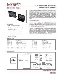
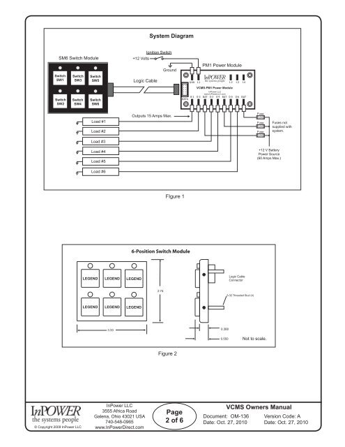
System Diagram<br />
SM6 Switch Module<br />
Switch<br />
SW1<br />
Switch<br />
SW3<br />
Switch<br />
SW5<br />
Ignition Switch<br />
+12 Volts<br />
Ground<br />
Logic Cable<br />
PM1 Power Module<br />
Switch<br />
SW2<br />
Switch<br />
SW4<br />
Switch<br />
SW6<br />
Load #1<br />
Load #2<br />
Load #3<br />
Fuse<br />
Outputs 15 Amps Max.<br />
20<br />
Fuse<br />
20<br />
Fuse<br />
20<br />
Fuses not<br />
supplied with<br />
system.<br />
Load #4<br />
Load #5<br />
+12 V Battery<br />
Power Source<br />
(60 Amps Max.)<br />
Load #6<br />
FIgure 1<br />
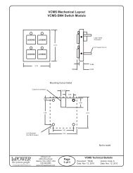
6-Position Switch Module<br />
Logic Cable<br />
Connector<br />
2.74<br />
3.33<br />
Not to scale.<br />
Figure 2<br />
© Copyright 2009 InPower <strong>LLC</strong><br />
InPower <strong>LLC</strong><br />
3555 Africa Road<br />
Galena, Ohio 43021 USA<br />
740-548-0965<br />
www.InPowerDirect.com<br />
Page<br />
2 of 6<br />
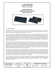
VCMS <strong>Owners</strong> <strong>Manual</strong><br />
Document: OM-136 Version Code: A<br />
Date: Oct. 27, 2010 Date: Oct. 27, 2010