Create successful ePaper yourself
Turn your PDF publications into a flip-book with our unique Google optimized e-Paper software.
4. Switch Legends Continued<br />
Figure 5 - Switch Module<br />
fully assembled.<br />
Figure 6 - Switch Module with<br />
top case removed.<br />
Figure 7 - Switch Cap with<br />
printed legend and light diffuser<br />
assembled.<br />
Figure 8 - Switch cap, printed<br />
legend and light diffuser.<br />
Figure 9 - Switch cap with<br />
printed legend installed.<br />
Figure 10 - Switch Cap with<br />
printed legend and light diffuser<br />
installed.<br />
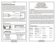
3. Installation<br />
3.1 Getting Started<br />
Determine the best location for the switch module and the power module. Allow for the routing of the communications logic<br />
cable between the modules. We recommend installing the cable in a cable loom for protection. You will need a crimping<br />
tool for the 0.25 inch faston blade terminals. Be sure to follow the crimping tool instructions for the proper wire size and<br />
terminals. The VCMS Input/Output diagram (Figure 11) is a key reference document in that is shows how the modules are<br />
configured. It also should be used to capture the switch legend descriptions used and the names of the 12 volt auxiliary<br />
devices being controlled by the system. Complete this document and keep it for a record of the as installed system.<br />
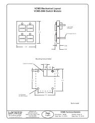
3.2 Mount the Switch Module<br />
Mount the switch module on a flat surface or mounting bracket using the four #6-32 threaded studs to secure the module<br />
to the panel. You will need to make a cutout for the logic cable connector (See Figure 3). Connect the logic cable to the<br />
switch module and route the cable to the power module.<br />
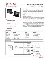
3.3 Mount the Power Module<br />
3.3.1 Determine the best location for the power module. Take into consideration the routing of the interconnecting logic<br />
cable that attaches to the 10-pin connector on the top of the module. Also take into consideration the routing of the wires<br />
to the power outputs, inputs and the +12 volt fused power source.<br />
© Copyright 2009 InPower <strong>LLC</strong><br />
InPower <strong>LLC</strong><br />
3555 Africa Road<br />
Galena, Ohio 43021 USA<br />
740-548-0965<br />
www.InPowerDirect.com<br />
Page<br />
4 of 6<br />
VCMS <strong>Owners</strong> <strong>Manual</strong><br />
Document: OM-136 Version Code: A<br />
Date: Oct. 27, 2010 Date: Oct. 27, 2010