PFC Manual - Schoonover, Inc.
PFC Manual - Schoonover, Inc.
PFC Manual - Schoonover, Inc.

You also want an ePaper? Increase the reach of your titles
YUMPU automatically turns print PDFs into web optimized ePapers that Google loves.
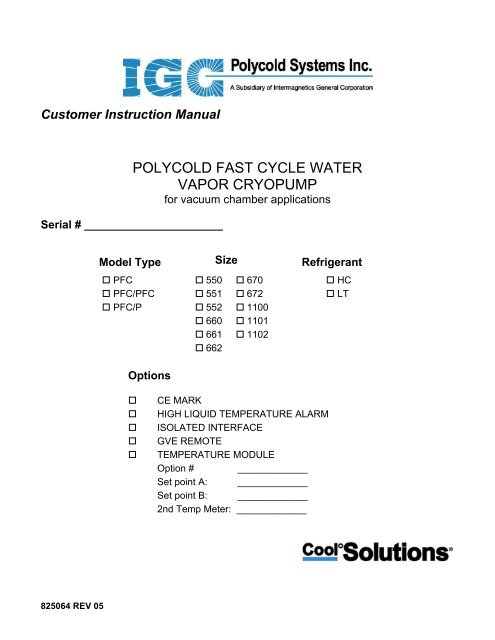
Customer Instruction <strong>Manual</strong><br />
Serial # ______________________<br />
POLYCOLD FAST CYCLE WATER<br />
VAPOR CRYOPUMP<br />
for vacuum chamber applications<br />
Model Type Size Refrigerant<br />
<strong>PFC</strong><br />
<strong>PFC</strong>/<strong>PFC</strong><br />
<strong>PFC</strong>/P<br />
Options<br />
550<br />
551<br />
552<br />
660<br />
661<br />
662<br />
670<br />
672<br />
1100<br />
1101<br />
1102<br />
HC<br />
LT<br />
<br />
<br />
<br />
<br />
<br />
CE MARK<br />
HIGH LIQUID TEMPERATURE ALARM<br />
ISOLATED INTERFACE<br />
GVE REMOTE<br />
TEMPERATURE MODULE<br />
Option # _____________<br />
Set point A: _____________<br />
Set point B: _____________<br />
2nd Temp Meter: _____________<br />
825064 REV 05
825064 REV 05 i
IGC Polycold Systems <strong>Inc</strong>.<br />
3800 Lakeville Highway<br />
Petaluma, CA 94954<br />
U.S.A.<br />
Tel: (1) 707-769-7000<br />
Fax: (1) 707-769-1380<br />
Service:<br />
Contact IGC Polycold at http://www.polycold.com or the 24 hour emergency number<br />
(1) (415) 258-4811 for the nearest service representative.<br />
Before starting:<br />
Congratulations for purchasing an IGC Polycold ® Cool Solutions ® Fast Cycle Water Vapor<br />
Cryopump. If any assistance is needed, please contact a local sales representative or IGC Polycold<br />
Systems <strong>Inc</strong>.<br />
To contact IGC Polycold Systems <strong>Inc</strong>. by:<br />
Telephone: (1) (707) 769-7000<br />
Toll Free: (1) (888) 4Polycold “within USA only”<br />
Fax (1) (707) 769-1380<br />
e-mail service@polycold.com<br />
Mail: 3800 Lakeville Hwy, Petaluma, CA 94954 U.S.A.<br />
Website: http://www.polycold.com<br />
24-hour<br />
Service #: (1) (415) 258-4811<br />
Please have the following information available to help us expedite the service process:<br />
Polycold ® Model: __________________________<br />
Polycold ® Serial No: ________________________<br />
Date Manufactured: ________________________<br />
The above information is on the nameplate of the Fast Cycle Water Vapor Cryopump. It is<br />
best to enter this information now (before the equipment is installed).<br />
825064 REV 05 ii
825064 REV 05 iii
© 2003 by IGC Polycold Systems <strong>Inc</strong>.<br />
All rights reserved.<br />
Printed in the United States of America.<br />
Trademark Recognition:<br />
Armaflex ® is a registered trademark of Armstrong World Industries, <strong>Inc</strong>.<br />
CPI UltraSeal is a trademark of Parker Hannifin Corporation.<br />
Phillips ® is a registered trademark of Phillips Screw Company.<br />
Polycold ® is a registered trademark of IGC Polycold Systems <strong>Inc</strong>.<br />
VCR ® is a registered trademark of Cajon Company.<br />
is a registered trademark of IGC Polycold Systems <strong>Inc</strong>.<br />
IGC Polycold ® <strong>PFC</strong> water vapor cryopumps (the “Products”), are warranted to be free from<br />
defects in materials and/or workmanship under normal service for a period of 24 months<br />
from date of shipment from IGC Polycold Systems <strong>Inc</strong>. Our obligation under this warranty is<br />
limited to the repair or replacement, at our option, of any parts that we determine, upon our<br />
examination, to be defective. Our repair or replacement of the defective Product(s) during<br />
the warranty period, ex-works IGC-Polycold’s factory, shall constitute fulfillment of our<br />
warranty obligation to Purchaser. We will not be liable for loss, damage or other expenses<br />
directly or indirectly arising from the use of the Products or from any other cause. We will<br />
not assume liability for expenses or repairs made outside of our factory, except by written<br />
consent.<br />
Every claim on account of defective material or workmanship shall be deemed waived<br />
unless made in writing within the warranty period specified above. The foregoing warranty<br />
is in lieu of all other warranties expressed or implied. We do not assume, or authorize any<br />
other person to assume, any other obligations or liabilities in connection with the sale of the<br />
Products. This warranty shall be void if we determine that the equipment has been<br />
subjected to misuse, negligence, corrosive atmospheres, attack by free chemicals within the<br />
system, accident or is operated contrary to our recommendation, or if the serial number has<br />
been altered, defaced or removed.<br />
825064 REV 05 iv
825064 REV 05 v
825064 REV 05 vi<br />
Table of Contents<br />
1 SAFETY INFORMATION ............................................................................................................... 1-1<br />
1.1 Safety Hazards and Safeguards.................................................................................................. 1-3<br />
1.2 Danger, Warning, and Caution Alerts........................................................................................ 1-4<br />
1.3 Safety Training Guidelines ........................................................................................................ 1-6<br />
1.4 Potential Hazards During Maintenance and Servicing .............................................................. 1-8<br />
1.5 Lock-Out and Tag-Out Instructions (LOTO) .......................................................................... 1-17<br />
1.6 Safety Interlocks ...................................................................................................................... 1-18<br />
1.7 Circuit Breaker and Fuse Protection........................................................................................ 1-18<br />
2 OVERVIEW ...................................................................................................................................... 2-1<br />
2.1 General Precautions ................................................................................................................... 2-3<br />
2.2 Emergency Shut-Down Procedures ........................................................................................... 2-7<br />
2.3 The Polycold Fast Cycle Water Vapor Cryopump and its Applications ................................... 2-8<br />
2.4 Refrigeration Unit Features ..................................................................................................... 2-10<br />
2.5 Location of Isolation & Solenoid Valves................................................................................. 2-12<br />
2.6 Refrigeration Unit Data ........................................................................................................... 2-13<br />
2.7 Recommended Items to Keep in Stock.................................................................................... 2-14<br />
3 INSTALLATION .............................................................................................................................. 3-1<br />
3.1 How to Install the Cryosurface .................................................................................................. 3-3<br />
3.1.1 If the Cryosurface is a Coil ................................................................................................ 3-3<br />
3.1.2 If the Cryosurface Is a Baffle............................................................................................. 3-5<br />
3.2 How to Install the Refrigeration Unit ........................................................................................ 3-6<br />
3.2.1 Inspect the Unit.................................................................................................................. 3-6<br />
3.2.2 Position the Unit ................................................................................................................ 3-8<br />
3.2.3 Connect the Electrical Power........................................................................................... 3-14<br />
3.2.4 Connect the Cooling Water.............................................................................................. 3-23<br />
3.2.5 How to Install the Refrigeration Unit to ASHRAE Requirements .................................. 3-26<br />
3.3 How to Connect the Cryosurface to the Refrigeration Unit..................................................... 3-28<br />
3.3.1 Connect the Refrigerant Line........................................................................................... 3-28<br />
3.3.2 Check the Refrigerant Line & Cryosurface for Leaks ..................................................... 3-34<br />
3.3.3 Evacuate the Refrigerant Line and Cryosurface .............................................................. 3-38<br />
3.3.4 Connect the COIL IN & COIL OUT Thermocouples ..................................................... 3-40<br />
3.4 How to Prepare the Cryopump for Operation.......................................................................... 3-43<br />
3.4.1 Open the Isolation Valves................................................................................................ 3-43<br />
3.4.2 Cycle the Cryopump & Check for Refrigerant Leaks...................................................... 3-44<br />
3.4.3 Insulate the Exposed Tubes and Couplings ..................................................................... 3-46<br />
3.4.4 Evaluate the Cryopump ................................................................................................... 3-48<br />
3.5 Cryosurface & Cryogenic Feedthrough Specification ............................................................. 3-54<br />
3.5.1 If the Cryosurface is a Coil .............................................................................................. 3-54<br />
3.5.2 If the Cryosurface is a Baffle........................................................................................... 3-58<br />
3.6 Refrigerant Line Specification................................................................................................. 3-60<br />
3.7 Brazing Specification............................................................................................................... 3-63<br />
3.8 How to Install the Remote Control (Optional) ........................................................................ 3-64<br />
3.8.1 Connect the Remote Control to a Remote Connector...................................................... 3-64<br />
3.8.2 Additional Instructions for Remote Temperature Indication........................................... 3-71<br />
4 OPERATION..................................................................................................................................... 4-1<br />
4.1 What the Cryopump Does in STANDBY, COOL, & DEFROST ............................................. 4-3<br />
4.2 How to Use the Cryopump ........................................................................................................ 4-4<br />
4.2.1 If the Cryosurface is a Coil ................................................................................................ 4-4<br />
4.2.2 If the Cryosurface is a Baffle............................................................................................. 4-5<br />
5 PERIODIC INSPECTION & MAINTENANCE .............................................................................. 5-1
5.1 Record Temperatures and Pressures Every Month.................................................................... 5-3<br />
5.2 Check the Cryopump Every Six Months ................................................................................... 5-5<br />
6 MODEL HISTORY........................................................................................................................... 6-1<br />
6.1 Review of Configurations.......................................................................................................... 6-3<br />
6.1.1 <strong>PFC</strong> 1101 ........................................................................................................................... 6-3<br />
6.1.2 <strong>PFC</strong> 1102 ........................................................................................................................... 6-3<br />
6.1.3 <strong>PFC</strong> 661 ............................................................................................................................. 6-5<br />
6.1.4 <strong>PFC</strong> 662 and 672................................................................................................................ 6-5<br />
6.1.5 <strong>PFC</strong> 670 ............................................................................................................................. 6-6<br />
6.1.6 <strong>PFC</strong> 551 ............................................................................................................................. 6-6<br />
6.1.7 <strong>PFC</strong> 552 ............................................................................................................................. 6-6<br />
7 TROUBLESHOOTING..................................................................................................................... 7-1<br />
7.1 What to Do If the Cryopump Stops Running............................................................................. 7-3<br />
7.1.1 Low (Suction) Pressure Lamp is Lighted .......................................................................... 7-5<br />
7.1.2 High (Discharge) Pressure Lamp is Lighted...................................................................... 7-6<br />
7.1.3 High Discharge Temperature Lamp Is Lighted ............................................................... 7-15<br />
7.1.4 High Liquid (Line) Temperature Lamp is Lighted .......................................................... 7-17<br />
7.1.5 “Unit OK” Lamp & Compressor Cycle Off & On........................................................... 7-19<br />
7.1.6 System Control Lamps are Off; Temperature Display & High Voltage Box Lamp are<br />
Lighted ......................................................................................................................................... 7-20<br />
7.1.7 System Control Lamps, Temperature Display & High Voltage Box Lamps are Off ...... 7-21<br />
7.1.8 SYSTEM CONTROL printed circuit board indicator lamps........................................... 7-22<br />
7.2 What to Do If the Cryosurface is Not Cryopumping Adequately............................................ 7-23<br />
7.2.1 Check Coil Temperatures ................................................................................................ 7-23<br />
7.2.2 COIL IN Temperature Is OK, But COIL OUT Temperature Is Not OK......................... 7-24<br />
7.2.3 COIL IN and COIL OUT Temperatures Are Not OK ..................................................... 7-26<br />
7.3 What to Do If the Cryosurface is Not Defrosting Adequately................................................. 7-27<br />
7.4 How to Calculate Voltage Unbalance...................................................................................... 7-29<br />
8 DISCONNECTION, STORAGE, AND RESHIPMENT.................................................................. 8-1<br />
8.1 How to Shut Down or Ship the Cryopump................................................................................ 8-3<br />
8.2 How to Disconnect the Refrigerant Line ................................................................................... 8-4<br />
8.3 How to Replace the Refrigerant................................................................................................. 8-7<br />
9 OPTIONS .......................................................................................................................................... 9-1<br />
9.1 CE Mark Units........................................................................................................................... 9-3<br />
9.2 Isolated Interface Option ........................................................................................................... 9-5<br />
9.3 Leybold Isolated Interface Option ........................................................................................... 9-14<br />
9.4 Temperature Module Options.................................................................................................. 9-18<br />
9.5 High Liquid Line Temperature Alarm Option......................................................................... 9-23<br />
9.6 How to Install the GVE Remote Control Option..................................................................... 9-25<br />
9.6.1 Connect the GVE Remote Control Option ...................................................................... 9-25<br />
10 GLOSSARY .................................................................................................................................... 10-1<br />
11 PROCESS & INSTRUMENTATION AND ELECTRICAL SCHEMATICS................................ 11-1<br />
825064 REV 05 vii
List of Tables<br />
Table 1-1: Warning Label Legend............................................................................................................ 1-4<br />
Table 1-2: <strong>PFC</strong> Circuit Breaker and Fuse Protection .............................................................................. 1-18<br />
Table 3-1: Acceptable Balance Pressures for Refrigeration Units † .......................................................... 3-7<br />
Table 3-2: <strong>PFC</strong> Dimensions.................................................................................................................... 3-10<br />
Table 3-3: Electrical Supply & Protection Requirements....................................................................... 3-18<br />
Table 3-4: Cooling Water Flow Requirements....................................................................................... 3-24<br />
Table 3-5: Pressure Relief Piping Requirements to Comply with ANSI / ASHRAE 15-1994 .............. 3-27<br />
Table 3-6: Pressures and Temperatures in Standby................................................................................ 3-49<br />
Table 3-7: Pressures and Temperatures in Cool ..................................................................................... 3-51<br />
Table 3-8: Cryosurface Temperature Needed for Desired Water........................................................... 3-52<br />
Table 3-9: Cryocoil Size Specification................................................................................................... 3-55<br />
Table 3-10: Remote Connector Wiring Worksheet ................................................................................ 3-67<br />
Table 5-1: Inspection Log......................................................................................................................... 5-4<br />
Table 9-1: Pressure Relief Piping Requirements to Comply with prEN378 ............................................ 9-4<br />
Table 9-2: Isolated Interface Option—Electrical Requirements............................................................... 9-6<br />
Table 9-3: Isolated Interface Option Parts List......................................................................................... 9-7<br />
Table 9-4: Isolated Interface Option—Isolated I/O Connector Wiring Worksheet................................ 9-13<br />
Table 9-5: Leybold Isolated Interface Option—Isolated I/O Connector Wiring Worksheet.................. 9-17<br />
Table 9-6: Remote Connector Wiring Worksheet .................................................................................. 9-28<br />
Table 11-1: Additional P & I D’s and Electrical Schematics ................................................................. 11-3<br />
825064 REV 05 viii<br />
List of Illustrations<br />
Figure 1-1: Typical Warning Labels......................................................................................................... 1-5<br />
Figure 1-2: Exterior Label Placement..................................................................................................... 1-13<br />
Figure 1-3: Interior Label Placement 550s, 552s, 660s, 662s, 670s, 672s (670 shown)......................... 1-14<br />
Figure 1-4: Interior Label Placement 1100............................................................................................. 1-15<br />
Figure 1-5: Interior Label Placement 1102............................................................................................. 1-16<br />
Figure 1-6: Power Disconnect Switch in OFF position –<br />
Unlocked (Left), Locked (Right) (Customer supplied lock out device not shown)................................. 1-17<br />
Figure 2-1: <strong>PFC</strong> cryopump—primary application.................................................................................... 2-9<br />
Figure 2-2: <strong>PFC</strong> cryopump—secondary application ................................................................................ 2-9<br />
Figure 2-3: <strong>PFC</strong> features......................................................................................................................... 2-11<br />
Figure 2-4: <strong>PFC</strong>/<strong>PFC</strong> & <strong>PFC</strong>/P—additional features ............................................................................. 2-11<br />
Figure 2-5: Location of isolation & solenoid valves .............................................................................. 2-12<br />
Figure 3-1: Polycold’s 2-inch (50 mm) feedthrough with port requirements........................................... 3-4<br />
Figure 3-2: Unit placement considerations............................................................................................... 3-9<br />
Figure 3-3: Compressor hold-down nuts location .................................................................................... 3-9<br />
Figure 3-4: <strong>PFC</strong> Footprint....................................................................................................................... 3-11<br />
Figure 3-5: Electrical Block Diagram..................................................................................................... 3-12<br />
Figure 3-6: Control voltage check—voltmeter connections................................................................... 3-16<br />
Figure 3-7: High voltage box panel removal; external ground stud locations........................................ 3-22<br />
Figure 3-8: High voltage box component locations................................................................................ 3-22<br />
Figure 3-9: Cooling water supply and drain lines location..................................................................... 3-25<br />
Figure 3-10: Parker CPI UltraSeal coupling........................................................................................... 3-29<br />
Figure 3-11: Cajon VCR coupling.......................................................................................................... 3-30<br />
Figure 3-12: Refrigerant line connection................................................................................................ 3-32<br />
Figure 3-13: Isolation valves location .................................................................................................... 3-33
Figure 3-14: Evacuation valve, refrigerant line & cryosurface relationship........................................... 3-35<br />
Figure 3-15: Refrigerant line & cryosurface—leak-check charging setup ............................................. 3-35<br />
Figure 3-16: Couplings—leak-checking method.................................................................................... 3-37<br />
Figure 3-17: Refrigerant line & cryosurface—evacuation setup ............................................................ 3-39<br />
Figure 3-18: Evacuation valve closure ................................................................................................... 3-39<br />
Figure 3-19: Low voltage box panel removal......................................................................................... 3-41<br />
Figure 3-20: Thermocouple (TC) positions identification...................................................................... 3-42<br />
Figure 3-21: Isolation valves location .................................................................................................... 3-44<br />
Figure 3-22: Insulating exposed tubes and couplings method................................................................ 3-47<br />
Figure 3-23: Compressor parts location.................................................................................................. 3-50<br />
Figure 3-24: Cooling water flow direction check................................................................................... 3-50<br />
Figure 3-25: Remote connector assembly............................................................................................... 3-66<br />
Figure 3-26: Wire side of remote connector plug................................................................................... 3-66<br />
Figure 3-27: Low voltage box panel removal......................................................................................... 3-69<br />
Figure 3-28: Jumper J11 location ........................................................................................................... 3-69<br />
Figure 6-1: <strong>PFC</strong> Model 1102 Hardware ................................................................................................ 6-4<br />
Figure 6-2: Electrical Changes to <strong>PFC</strong> Models with CE Mark................................................................. 6-4<br />
Figure 6-3: <strong>PFC</strong> Model 672 Hardware ................................................................................................... 6-5<br />
Figure 6-4: <strong>PFC</strong> Model 552 Hardware ................................................................................................... 6-6<br />
Figure 7-1: Unit indicator lamps............................................................................................................... 7-4<br />
Figure 7-2: Control voltage circuit breaker ............................................................................................ 7-21<br />
Figure 7-3: SYSTEM CONTROL printed circuit board indicator lamps............................................... 7-22<br />
Figure 8-1: Parker CPI UltraSeal coupling—O-ring removal tool usage................................................. 8-7<br />
Figure 9-1: <strong>PFC</strong> and <strong>PFC</strong>/<strong>PFC</strong> isolated interface option—internal wiring .............................................. 9-8<br />
Figure 9-2: <strong>PFC</strong> and <strong>PFC</strong>/<strong>PFC</strong> isolated interface option.......................................................................... 9-9<br />
Figure 9-3: <strong>PFC</strong>/P isolated interface option—internal wiring................................................................ 9-10<br />
Figure 9-4: <strong>PFC</strong>/P isolated interface option—suggested wiring for customer’s control system............ 9-11<br />
Figure 9-5: Isolated interface option—wire side of isolated I/O connector plug ................................... 9-12<br />
Figure 9-6: Leybold isolated interface option- schematic ...................................................................... 9-15<br />
Figure 9-7: Leybold isolated interface option – wiring side of isolated I/O connector plug .................. 9-16<br />
Figure 9-8: Temperature module options identification ......................................................................... 9-19<br />
Figure 9-9: Temperature module options—parts identification for option 600212-02 .......................... 9-21<br />
Figure 9-10: Temperature module options—parts identification for option 600212-03 ........................ 9-21<br />
Figure 9-11: Temperature module options—parts identification for option 600212-04 ........................ 9-22<br />
Figure 9-12: Wire side of remote connector plug................................................................................... 9-27<br />
Figure 11-1: Cryopump simplified controls diagram (6-2) ................................................................... 11-5<br />
Figure 11-2: High voltage box (6-3)....................................................................................................... 11-6<br />
Figure 11-3: High voltage box—575 V compressor only (6-4).............................................................. 11-7<br />
Figure 11-4: SYSTEM CONTROL printed circuit board (6-5) ............................................................. 11-8<br />
Figure 11-5: <strong>PFC</strong> refrigerant circuit controls—printed circuit board with panel (6-7) .......................... 11-9<br />
Figure 11-6: <strong>PFC</strong> remote connector functions with suggested wiring (6-8)......................................... 11-10<br />
Figure 11-7: <strong>PFC</strong>/<strong>PFC</strong> remote connector functions with suggested wiring (6-9) ................................ 11-11<br />
Figure 11-8: <strong>PFC</strong>/P remote connector functions with suggested wiring (6-10) ................................... 11-12<br />
825064 REV 05 ix
Safety Information<br />
<strong>PFC</strong> <strong>Manual</strong><br />
1 SAFETY INFORMATION<br />
825064 REV 05 Page 1-1
Safety Information<br />
<strong>PFC</strong> <strong>Manual</strong><br />
825064 REV 05 Page 1-2
Safety Information<br />
<strong>PFC</strong> <strong>Manual</strong><br />
1.1 Safety Hazards and Safeguards<br />
This chapter summarizes safety concerns (hazards, precautions, and ergonomics)<br />
associated with the operation and service of Polycold’s Cool Solutions ® Fast Cycle<br />
Water Vapor Cryopump.<br />
The Fast Cycle Water Vapor Cryopump has been designed to conform to all known<br />
safety requirements applicable to IGC-Polycold Systems, <strong>Inc</strong>. wafer fab equipment.<br />
Under normal operation the direct refrigeration and heating equipment present no<br />
hazard to its operator or other personnel. Tool secured access panels shield operators<br />
and other personnel working in the area of the equipment from the operation or<br />
possible failure of the components that compose the equipment.<br />
Only qualified service personnel are authorized to open or remove the panels and<br />
must be in accordance with the safety instructions presented in this chapter and<br />
throughout the manual. In service and repair operations, the direct refrigeration and<br />
heating equipment may potentially expose personnel to the following hazards:<br />
• Electrical shock<br />
• Hazardous Materials<br />
• Lifting Hazards<br />
• Cold Surfaces<br />
• Hot Surfaces<br />
The information and instructions provided in this chapter and throughout this manual<br />
are intended to help service personnel work with the equipment in a safe, effective,<br />
and efficient manner. The emergency and safety procedures are provided to help<br />
service personnel develop safe practices and establish safe conditions for working with<br />
Polycold’s Cool Solutions ® Fast Cycle Water Vapor Cryopump.<br />
825064 REV 05 Page 1-3
Safety Information<br />
<strong>PFC</strong> <strong>Manual</strong><br />
1.2 Danger, Warning, and Caution Alerts<br />
Danger, Warning, and Caution alerts are integral parts of these instructions:<br />
• DANGER is used to indicate an imminently hazardous situation that, if not<br />
avoided, will result in death or serious injury.<br />
• WARNING is used to indicate a potentially hazardous situation that, if not<br />
avoided, could result in death or serious injury.<br />
• CAUTION is used to indicate a potentially hazardous situation that, if not<br />
avoided, may result in minor or moderate injury.<br />
• CAUTION is also used when failure to follow instructions or precautions can<br />
result in damage to the equipment.<br />
Danger, Warning, and Caution alerts must be read carefully, understood thoroughly,<br />
and observed at all times. If this equipment is used in a manner not specified by the<br />
manufacturer, the protection provided by the equipment may be impaired. Pictorial<br />
hazard alerts affixed to the direct refrigeration and heating equipment and its<br />
components are in accordance with ANSI, FDA, SEMI, and (where applicable) IEC<br />
standards. Pictorial hazard alerts follow the format described below:<br />
Hazard<br />
Keyword<br />
Level<br />
Pictogram (icon)<br />
depicting nature<br />
of hazard<br />
‡<br />
WARNING †<br />
HAZARDOUS VOLTAGE<br />
Contact may cause electric shock or burn and could<br />
result in death or serious injury.<br />
Turn off and lock-out system before servicing.<br />
Text describing how<br />
to avoid the hazard<br />
`<br />
DANGER - White Lettering / Red Background<br />
(Safety Red: per ANSI Z535.4 - 15 parts Warm Red, 1 part Rubine<br />
Red, 1/4 part Black)<br />
WARNING - Black Lettering / Orange Background<br />
(Safety Orange: per ANSI Z535.4 - 13 parts Yellow, 3 parts Warm<br />
Red, 1/4 part Black)<br />
CAUTION - Black Lettering / Yellow Background<br />
(Safety Yellow: per ANSI Z535.4 - Pantone 108C)<br />
Table 1-1: Warning Label Legend<br />
Text describing<br />
hazard and what<br />
might / could happen<br />
‡<br />
SAFETY ALERT SYMBOL<br />
White Triangle / Red Exclamation Point<br />
Black Triangle / Orange Exclamation Point<br />
Black Triangle / Yellow Exclamation Point<br />
825064 REV 05 Page 1-4
Safety Information<br />
<strong>PFC</strong> <strong>Manual</strong><br />
This page includes pictogram representations used on semiconductor manufacturing<br />
equipment. Some of these pictograms will be found on Polycold’s Cool Solutions ® Fast<br />
Cycle Water Vapor Cryopump equipment. Actual label configurations and placement will<br />
be found in this chapter. Please note, for purposes of clarity, most illustrations depicting<br />
hazardous exposures show components in their most hazardous state (i.e., covers<br />
removed, safety interlocks, and other safeguards defeated) as they might appear during a<br />
major service activity. Most tasks do not require that the hazards be exposed to this<br />
degree.<br />
Figure 1-1: Typical Warning Labels<br />
825064 REV 05 Page 1-5
Safety Information<br />
<strong>PFC</strong> <strong>Manual</strong><br />
1.3 Safety Training Guidelines<br />
The safety information in this chapter is a summary of the safety information that is to<br />
be successfully conveyed to service personnel as part of their training on Polycold’s<br />
Cool Solutions ® Fast Cycle Water Vapor Cryopump. The training program is intended<br />
to ensure that any person who undertakes the service of the Fast Cycle Water Vapor<br />
Cryopump can demonstrate competence to perform the required tasks safely.<br />
Accordingly, training required for each task includes, but is not limited to, the following:<br />
• A review of applicable safety standards and procedures, such as those<br />
presented in this chapter.<br />
• A review of maintenance and safety recommendations applicable to vendor<br />
supplied equipment.<br />
• An explanation of the purpose of a subsystem and its operation.<br />
• An explanation of the specific tasks and responsibilities of each person<br />
(operator, service personnel, etc.) assigned to the Fast Cycle Water Vapor<br />
Cryopump equipment.<br />
• The person(s) (identified by name, location, and telephone number) to be<br />
contacted when required actions are beyond the training and responsibility of<br />
the person being trained.<br />
• Identification of the recognized hazards associated with each task.<br />
• Identification of, and appropriate responses to, unusual operating conditions.<br />
• Explanation of the functions and limitations of all safeguards and their design<br />
characteristics.<br />
• Instructions for the functional testing (or other means of assurance) for proper<br />
operation of safeguarding devices.<br />
Safe use and service of the Fast Cycle Water Vapor Cryopump equipment also<br />
requires the following:<br />
• Service personnel should understand the operation of process-related hardware<br />
interlocks, and the sequences of hardware operation that are executed<br />
automatically, as explained in this chapter.<br />
• The equipment should not be used without assuring correct operation of all<br />
connected facilities, especially fugitive emissions exhaust.<br />
• Service personnel should always assume that high voltage is present unless<br />
they have personally turned it off and locked it out.<br />
• The equipment should not be operated without all guards and safety devices in<br />
place.<br />
• The equipment should be shutdown, locked-out, and not be operated while it is<br />
being maintained.<br />
• Users should not attempt to defeat, modify, or disable any of the equipment's<br />
safety interlock switches.<br />
• Only IGC-Polycold Systems, <strong>Inc</strong>. trained service personnel should perform<br />
installation, assembly, operation, disassembly, service, or maintenance of the<br />
Fast Cycle Water Vapor Cryopump equipment.<br />
825064 REV 05 Page 1-6
Safety Information<br />
<strong>PFC</strong> <strong>Manual</strong><br />
• All safety related incidents or near misses should be reported to a supervisor or<br />
to IGC-Polycold Systems, <strong>Inc</strong>.<br />
• The user should carefully review and understand manufacturer provide material<br />
safety data sheets (MSDS) for materials used by this equipment.<br />
Definition of Electrical Work Types<br />
The following are the four types of electrical work in SEMI S2-0200:<br />
Type 1- Equipment is fully deenergized.<br />
Type 2- Equipment is energized. Energized circuits are covered or protected.<br />
Note: Type 2 work includes tasks where the energized circuits are or can be measured<br />
by placing probes through suitable openings in the covers or insulators.<br />
Type 3- Equipment is energized. Energized circuits are exposed and inadvertent<br />
contact with uninsulated energized parts is possible. Potential exposures are no<br />
greater than 30 volts rms, 42.4 volts peak, 60 volts dc or 240 volt-amps in dry<br />
locations.<br />
Type 4- Equipment is energized. Energized circuits are exposed and inadvertent<br />
contact with uninsulated energized parts is possible. Potential exposures are greater<br />
than 30 volts rms, 42.4 volts peak, 60 volts dc or 240 volt-amps in dry locations.<br />
Potential exposures to radio-frequency currents exist; refer to SEMI S2-0200, Table<br />
A5-1 of Appendix 5 for a listing of these values.<br />
825064 REV 05 Page 1-7
Safety Information<br />
<strong>PFC</strong> <strong>Manual</strong><br />
1.4 Potential Hazards During Maintenance and Servicing<br />
1<br />
WARNING!<br />
VALVE UNDER PRESSURE<br />
WHENEVER SYSTEM IS<br />
PRESSURIZED<br />
2<br />
CAUTION!<br />
PREVENT LEAKS - CAP<br />
THE VALVE<br />
3<br />
WARNING!<br />
This valve is to remain sealed open. If<br />
this valve is closed when servicing the<br />
unit, the unit must be attended until the<br />
valve is reopened and resealed.<br />
4<br />
CAUTION!<br />
Hot<br />
Surface<br />
Inside<br />
825064 REV 05 Page 1-8
Safety Information<br />
<strong>PFC</strong> <strong>Manual</strong><br />
5<br />
This valve is only open<br />
when the valve stem is<br />
in the middle position<br />
(midseated)<br />
6<br />
PRIMARY REFRIGERANT<br />
EXPANSION<br />
407020 REV 01 XQS23689<br />
8<br />
R2000 SERIES<br />
9<br />
(CE Marked Units Only)<br />
10<br />
24 V AC<br />
PUSH TO RESET<br />
825064 REV 05 Page 1-9
Safety Information<br />
<strong>PFC</strong> <strong>Manual</strong><br />
11<br />
CAUTION<br />
Extreme Temperatures.<br />
Can cause burns or frostbite.<br />
Do not touch exposed piping.<br />
12<br />
13<br />
WARNING<br />
FLAMMABLE MATERIAL (1101, 1100, 670, 661, 660, 551, and 550 ONLY)<br />
Do not open the refrigerant circuit to the atmosphere. Do not change the settings<br />
of the valves or loosen any fittings. Opening the refrigerant circuit or changing<br />
valve settings along with the failure to following instructions in this manual could<br />
result in death or serious injury.<br />
Review this manual before performing any procedure including routine operation of<br />
Polycold’s Cool Solutions ® Fast Cycle Water Vapor Cryopump. Inspect the<br />
refrigerant circuit and change valve settings only as defined throughout this<br />
manual.<br />
825064 REV 05 Page 1-10
Safety Information<br />
<strong>PFC</strong> <strong>Manual</strong><br />
14<br />
825064 REV 05 Page 1-11
Safety Information<br />
<strong>PFC</strong> <strong>Manual</strong><br />
15<br />
825064 REV 05 Page 1-12
Safety Information<br />
<strong>PFC</strong> <strong>Manual</strong><br />
Figure 1-2: Exterior Label Placement<br />
Dual Circuit<br />
units only<br />
14<br />
15<br />
9<br />
11<br />
11<br />
11 11<br />
12<br />
10<br />
5<br />
Exterior, Left Front Oblique<br />
Exterior, Right Rear Oblique<br />
825064 REV 05 Page 1-13
Safety Information<br />
<strong>PFC</strong> <strong>Manual</strong><br />
Figure 1-3: Interior Label Placement 550s, 552s, 660s, 662s, 670s, 672s (670 shown)<br />
2<br />
6<br />
2<br />
3<br />
6<br />
1<br />
1<br />
5<br />
Interior, Left Front Oblique<br />
Interior, Right Rear Oblique<br />
825064 REV 05 Page 1-14
Safety Information<br />
<strong>PFC</strong> <strong>Manual</strong><br />
Figure 1-4: Interior Label Placement 1100<br />
2<br />
1<br />
6<br />
2<br />
2<br />
10<br />
5<br />
3<br />
Interior, Left Front Oblique<br />
Interior, Right Rear Oblique<br />
825064 REV 05 Page 1-15
Safety Information<br />
<strong>PFC</strong> <strong>Manual</strong><br />
Figure 1-5: Interior Label Placement 1102<br />
1<br />
3<br />
2<br />
2<br />
6<br />
10<br />
2<br />
5<br />
Interior, Left Front Oblique<br />
Interior, Right Rear Oblique<br />
825064 REV 05 Page 1-16
Safety Information<br />
<strong>PFC</strong> <strong>Manual</strong><br />
1.5 Lock-Out and Tag-Out Instructions (LOTO)<br />
Note: A lock-out refers to disconnecting the power supply from the unit, and reapplying<br />
safe power in order to avoid possible personnel electrocution.<br />
WARNING<br />
ELECTRICAL HAZARD<br />
Contact could cause electric shock and result in death or serious injury.<br />
After performing LOTO of the Power Disconnect Switch, Line Voltage is still present<br />
at input terminals of the Power Disconnect Switch. To remove electrical power to the<br />
input terminals of the Power Disconnect Switch, refer to end-user’s Facility Power<br />
LOTO instructions.<br />
1. Shut down the system as described in section 7.1 How to Shut Down or Ship the<br />
Cryopump.<br />
2. Switch the Power Disconnect switch (refer to figure below) to the OFF position.<br />
3. Pull out the Tag (shown in lower right picture below) on Power Disconnect Switch and<br />
place a pad lock in the opening keep the power off and locked.<br />
4. Using an appropriate test meter, verify no electrical potential exists on secondary side<br />
of Power Disconnect Switch.<br />
5. It is now safe to work in this area, refer to the Type 3 Electrical Work instructions<br />
before proceeding.<br />
Figure 1-6: Power Disconnect Switch in OFF position –<br />
Unlocked (Left), Locked (Right) (Customer supplied lock out device not shown)<br />
825064 REV 05 Page 1-17
Safety Information<br />
<strong>PFC</strong> <strong>Manual</strong><br />
1.6 Safety Interlocks<br />
The <strong>PFC</strong> safety interlock circuitry design is a positive logic, hardware based, fault tolerant<br />
device (approved by an authorized testing agency and NRTL approved for use as a safety<br />
device), providing operator notification, requiring manual reset, and which places the<br />
equipment in a safe standby condition upon activation. An exception to this is the<br />
compressor discharge safety interlock that uses negative logic. The risk associated with<br />
this variance has been deemed to be acceptable since other interlocks (which use positive<br />
logic) are expected to be activated if abnormally high discharge temperatures occur.<br />
1.7 Circuit Breaker and Fuse Protection<br />
Table 1-2: <strong>PFC</strong> Circuit Breaker and Fuse Protection<br />
High Voltage<br />
Box<br />
Reference<br />
Designation<br />
Protection<br />
Provided<br />
Rated Voltage<br />
and Amperage<br />
CB1 Over Current 460V 1A<br />
CB2 Over Current 460V 1A<br />
CB3 Over Current 24VAC 5A<br />
*Amperage<br />
Interrupting<br />
Capacity<br />
High Voltage FU1 Over Current 600V 1A Not Applicable<br />
Box- 575V FU2 Over Current 600V 1A Not Applicable<br />
Compressor CB1 Over Current 24VAC 5A<br />
System F1 Over Current 24VAC 1A Not Applicable<br />
Control<br />
Printed<br />
Circuit Board<br />
*Note: Amperage Interrupting Capacity refers to the maximum current that the electrical component is<br />
rated for. If the current is too high the contacts will “arc” exceeding capacity and possibly weld (fuse)<br />
together. In some locations this is also known as “AC breaking capacity.”<br />
825064 REV 05 Page 1-18
Overview<br />
<strong>PFC</strong> <strong>Manual</strong><br />
2 OVERVIEW<br />
825064 REV 05 Page 2-1
Overview<br />
<strong>PFC</strong> <strong>Manual</strong><br />
825064 REV 05 Page 2-2
Overview<br />
<strong>PFC</strong> <strong>Manual</strong><br />
2.1 General Precautions<br />
Review the instruction manual before performing any procedure including the routine<br />
operation of Polycold’s Cool Solutions ® Fast Cycle Water Vapor Cryopump.<br />
General precautions to follow at all times<br />
WARNING<br />
GENERAL HAZARD<br />
Failure to review this manual could result in death or serious injury.<br />
Review this manual before performing any procedure including routine operation of<br />
Polycold’s Cool Solutions ® Fast Cycle Water Vapor Cryopump.<br />
CAUTION<br />
GENERAL HAZARD<br />
United States federal law requires a certified refrigeration technician (Type 2, High<br />
Pressure) for any procedure that could release refrigerant to the atmosphere. This<br />
includes installing the cryopump, some inspection procedures, disconnecting the<br />
refrigerant lines, some troubleshooting procedures, repair, and disposal of the unit.<br />
A qualified refrigeration technician must do all refrigeration work.<br />
WARNING<br />
ELECTRICAL<br />
Failure to have a qualified electrician do all electrical work could result in death or<br />
serious injury.<br />
A qualified electrician must do all electrical work.<br />
DANGER<br />
GENERAL HAZARD<br />
Do not bypass or change the setting of any protective device. The repeated<br />
resetting of a protective device may void the warranty and, if not avoided, will cause<br />
death or serious injury.<br />
Review this manual before performing any procedure including routine operation of<br />
Polycold’s Cool Solutions ® Fast Cycle Water Vapor Cryopump. Reset protective<br />
devices only as defined throughout this manual.<br />
825064 REV 05 Page 2-3
Overview<br />
<strong>PFC</strong> <strong>Manual</strong><br />
Specific Hazards and How to Avoid Them<br />
Refrigeration unit (or cryopump, once installed) contains pressurized gas.<br />
WARNING<br />
FLAMMABLE MATERIAL (1101, 1100, 670, 661, 660, 551, and 550 ONLY)<br />
Do not open the refrigerant circuit to the atmosphere. Do not change the settings<br />
of the valves or loosen any fittings. Opening the refrigerant circuit or changing<br />
valve settings along with the failure to following instructions in this manual could<br />
result in death or serious injury.<br />
Review this manual before performing any procedure including routine operation of<br />
Polycold’s Cool Solutions ® Fast Cycle Water Vapor Cryopump. Inspect the<br />
refrigerant circuit and change valve settings only as defined throughout this<br />
manual.<br />
CAUTION<br />
GENERAL HAZARD<br />
Do not connect the refrigeration unit to an existing cryosurface unless it meets<br />
specification. Doing so could cause minor or moderate injury.<br />
See Section 3.5 “Cryosurface & Cryogenic Feedthrough Specification” for more<br />
information.<br />
DANGER<br />
GENERAL HAZARD<br />
Do not bypass or change the settings of any protective device on the refrigeration<br />
unit. Resetting of a protective device may void your warranty and, if not avoided, will<br />
cause death or serious injury.<br />
Review this manual before performing any procedure including routine operation of<br />
Polycold’s Cool Solutions ® Fast Cycle Water Vapor Cryopump. Do not bypass or<br />
change the settings of any protective devices on the refrigeration unit.<br />
Refrigerant is harmful to the environment and to human health. Refrigerant may<br />
also be flammable. (This warning does not apply to <strong>PFC</strong>- 552, 662, 672, and<br />
1102).<br />
WARNING<br />
CHEMICAL HAZARD<br />
Do not release refrigerant to the atmosphere. Opening the refrigerant circuit or<br />
changing valve settings along with the failure to following instructions in this manual<br />
could result in death or serious injury.<br />
Review this manual before performing any procedure including routine operation of<br />
Polycold’s Cool Solutions ® Fast Cycle Water Vapor Cryopump. Do not release<br />
refrigerant to the atmosphere.<br />
825064 REV 05 Page 2-4
Overview<br />
<strong>PFC</strong> <strong>Manual</strong><br />
CAUTION<br />
GENERAL HAZARD<br />
Failure to review this manual may result in minor or moderate injury.<br />
See the enclosed Material Safety Data Sheet (MSDS) section for additional<br />
information and protective measures for Polycold’s Cool Solutions ® Fast Cycle<br />
Water Vapor Cryopump.<br />
Hazardous voltages exist at all times after the power is connected.<br />
WARNING<br />
ELECTRICAL<br />
Failure to have a qualified electrician do all electrical work could result in death or<br />
serious injury.<br />
Do not reach inside the refrigeration unit. A qualified electrician must do all electrical<br />
work.<br />
Extreme temperatures (cold & hot) exist while the refrigeration unit is operating<br />
and for at least an hour after the unit is turned off.<br />
CAUTION<br />
EXTREME TEMPERATURES EXIST<br />
Extreme temperatures (cold & hot) exist while the refrigeration unit is operating and<br />
for at least an hour after the unit is turned off. Contact with a cold or hot surface may<br />
result in minor or moderate injury.<br />
Do not reach inside Polycold’s Cool Solutions ® Fast Cycle Water Vapor Cryopump’s<br />
refrigeration unit.<br />
CAUTION<br />
EXTREME TEMPERATURES EXIST<br />
Extreme temperatures (cold & hot) exist while the refrigeration unit is operating and<br />
for at least an hour after the unit is turned off. Contact with a cold or hot surface may<br />
result in minor or moderate injury.<br />
Do not touch any uninsulated part of the refrigerant circuit when the unit is operating.<br />
This includes the solenoid and hand valves, any uninsulated part of the refrigerant<br />
line or feedthrough, and the cryosurface. Also, do not reach inside Polycold’s Cool<br />
Solutions ® Fast Cycle Water Vapor Cryopump’s refrigeration unit.<br />
825064 REV 05 Page 2-5
Overview<br />
<strong>PFC</strong> <strong>Manual</strong><br />
CAUTION<br />
GENERAL HAZARD<br />
Moving or repositioning the refrigerant line may result in minor or moderate injury.<br />
Do not attempt to move or position the refrigerant line. The insulation hardens when<br />
cold and may crack.<br />
825064 REV 05 Page 2-6
Overview<br />
<strong>PFC</strong> <strong>Manual</strong><br />
2.2 Emergency Shut-Down Procedures<br />
Refrigerant Leak<br />
WARNING<br />
CHEMICAL HAZARD<br />
Do not release refrigerant to the atmosphere. Opening the refrigerant circuit or<br />
changing valve settings along with the failure to following instructions in this manual<br />
could result in death or serious injury.<br />
Review this manual before performing any procedure including routine operation of<br />
Polycold’s Cool Solutions ® Fast Cycle Water Vapor Cryopump. Do not release<br />
refrigerant to the atmosphere.<br />
1. For all leaks: Follow the instructions in the MSDS, especially if the leak is large.<br />
2. For a leak on the refrigerant line or cryosurface: If the leak is not too large, limit the<br />
amount of refrigerant lost. Follow the instructions in section 8.2 “How to Disconnect<br />
the Refrigerant Line.”<br />
Electrical Problem<br />
1. Turn off the unit.<br />
WARNING<br />
ELECTRICAL<br />
Failure to have a qualified electrician do all electrical work could result in death or<br />
serious injury.<br />
Do not reach inside the refrigeration unit. A qualified electrician must do all electrical<br />
work.<br />
2. Turn the power disconnect switch to the OFF position<br />
3. Disconnect the refrigeration unit from your electrical supply, if necessary.<br />
825064 REV 05 Page 2-7
Overview<br />
<strong>PFC</strong> <strong>Manual</strong><br />
2.3 The Polycold Fast Cycle Water Vapor Cryopump and its Applications<br />
The Polycold Fast Cycle Water Vapor Cryopump (<strong>PFC</strong>) is a cryogenic refrigeration<br />
system that captures volatile molecules by freezing them onto a cold surface. It<br />
consists of a refrigeration unit, a refrigerant line, and a cryosurface with cryogenic<br />
feedthrough. The refrigeration unit can pump cold or hot refrigerant in a continuous<br />
loop through the refrigerant line and cryosurface. The refrigerant is actually a<br />
proprietary mixture of refrigerants made by IGC Polycold Systems <strong>Inc</strong>.<br />
The primary application of the <strong>PFC</strong> is to capture water vapor in a vacuum chamber<br />
after opening the high vacuum valve. For this application, the cryosurface is normally<br />
a coil. The coil can be quickly cooled and defrosted to correspond with vacuum<br />
chamber cycles. See Figure 2-1.<br />
The <strong>PFC</strong> can also be used to control backstreaming. See Figure 2-2. For this<br />
application, the cryosurface is a baffle. “Fast Cycle” refers to the faster interchange<br />
between cool and defrost. However, quick cooling and defrosting is not normally<br />
required or desired for this application.<br />
Note: Backstreaming will contaminate the system because it is the process of hot<br />
vapor migrating and condensing on cold surfaces. When the vacuum pump is<br />
used, the pump oil heats up and travels opposite of the pumping direction and<br />
condenses the system resulting in system contamination.<br />
The <strong>PFC</strong>/<strong>PFC</strong> is the same as a <strong>PFC</strong> except that the <strong>PFC</strong>/<strong>PFC</strong> has two refrigerant<br />
circuits. Each refrigerant circuit services a separate cryosurface. Both cryosurfaces<br />
can be quickly defrosted.<br />
The <strong>PFC</strong>/P also has two refrigerant circuits. Each refrigerant circuit services a<br />
separate cryosurface. However, only the first refrigerant circuit can be quickly<br />
defrosted.<br />
825064 REV 05 Page 2-8
Overview<br />
<strong>PFC</strong> <strong>Manual</strong><br />
Figure 2-1: <strong>PFC</strong> cryopump—primary application<br />
A. Refrigeration unit<br />
B. Refrigerant line<br />
C. Cryogenic feedthrough<br />
D. Vacuum chamber wall<br />
E. Cryosurface<br />
Figure 2-2: <strong>PFC</strong> cryopump—secondary application<br />
A. Refrigeration unit<br />
B. Refrigerant line<br />
C. High vacuum valve<br />
D. Cryobaffle<br />
E. High vacuum pump<br />
825064 REV 05 Page 2-9
Overview<br />
<strong>PFC</strong> <strong>Manual</strong><br />
2.4 Refrigeration Unit Features<br />
See Figures 2-3 & 2-4.<br />
Couplings for the Refrigerant Line<br />
A. #1 Return<br />
B. #1 Feed<br />
Low Voltage Box<br />
C. The EXTERNAL TC port allows thermocouples on the refrigerant line to be connected to the TC<br />
SELECT switch. See section 3.3.4, “Connect the COIL IN & COIL OUT Thermocouples” for more<br />
information.<br />
D. The TEMPERATURE module displays the temperatures of various thermocouples that will help<br />
monitor the cryopump. See Figure 3-20 “Thermocouple (TC) Positions Identification” and section<br />
3.8.2 “Additional Instructions for Remote Temperature Indication” for more information.<br />
E. The SYSTEM CONTROL module will help troubleshoot the cryopump if a protective device has shut<br />
it off. See section 7.1 “What to do if the Cryopump Stops Running” for more information.<br />
F. The <strong>PFC</strong> CIRCUIT 1 module controls the refrigerant circuit. See section 4.1 “What the Cryopump<br />
does in STANDBY, COOL, & DEFROST” for more information.<br />
I. The REMOTE connector permits remote control of the unit and provides status information to a<br />
remote location. See section 3.8 “How to Install the GVE Remote Control Option” for more<br />
information.<br />
High Voltage Box<br />
J. The power disconnect switch disconnects the main power when it is in the OFF (O) position. The<br />
switch must be in the OFF (O) position to open the high voltage box.<br />
Utility Panel<br />
K. REFRIGERANT connections (EVACUATION VALVE and PRESSURE RELIEF OUTLET)<br />
L. COOLING WATER connections<br />
Other<br />
G. Pocket for manual<br />
H. Nameplate (above the REMOTE connector)<br />
M. COMPRESSOR PRESSURE gauges<br />
For <strong>PFC</strong>/<strong>PFC</strong> or <strong>PFC</strong>/P<br />
N. #2 Return<br />
O. #2 Feed<br />
P. The <strong>PFC</strong> CIRCUIT 2 or COOLING CIRCUIT 2 module controls a second refrigerant circuit. See<br />
section 4.1 “What the Cryopump does in STANDBY, COOL, & DEFROST” for more information.<br />
825064 REV 05 Page 2-10
Overview<br />
<strong>PFC</strong> <strong>Manual</strong><br />
Figure 2-3: <strong>PFC</strong> features<br />
Figure 2-4: <strong>PFC</strong>/<strong>PFC</strong> & <strong>PFC</strong>/P—additional features<br />
825064 REV 05 Page 2-11
Overview<br />
<strong>PFC</strong> <strong>Manual</strong><br />
2.5 Location of Isolation & Solenoid Valves<br />
Figure 2-5: Location of isolation & solenoid valves<br />
A. Cold gas feed isolation valve<br />
B. Hot gas feed isolation valve<br />
C. Common return isolation valve<br />
D. #2 Cool solenoid valve (<strong>PFC</strong>/<strong>PFC</strong> or <strong>PFC</strong>/P only)<br />
E. #1 Cool solenoid valve<br />
F. Buffer tank solenoid valve (660s & 1100s only)<br />
G. Defrost solenoid valve<br />
H. #2 Defrost solenoid valve (<strong>PFC</strong>/<strong>PFC</strong> only)<br />
825064 REV 05 Page 2-12
Overview<br />
<strong>PFC</strong> <strong>Manual</strong><br />
2.6 Refrigeration Unit Data<br />
Refrigeration<br />
Unit<br />
Dimensions<br />
Width x Depth x Height<br />
in (mm)<br />
Weight or<br />
Mass<br />
lb (kg)<br />
900<br />
(408)<br />
1055<br />
(478)<br />
1050<br />
(476)<br />
1200<br />
(544)<br />
1200<br />
(544)<br />
550, 551, 552 37.5 x 26 x 72.5<br />
(953 x 660 x 1842)<br />
660, 661, 670, 37.5 x 26 x 72.5<br />
672<br />
(953 x 660 x 1842)<br />
662 37.5 x 26 x 72.5<br />
(953 x 660 x 1842)<br />
1100, 1101 41.5 x 28 x 66.5<br />
(1054 x 711 x 1689)<br />
1102 41.5 x 28 x 66.5<br />
(1054 x 711 x 1689)<br />
† Notes regarding maximum sound pressure level:<br />
Maximum Sound<br />
Pressure Level<br />
dB(A)†<br />
71<br />
72<br />
72<br />
81<br />
73<br />
Units were tested in a manufacturing environment while under maximum<br />
load in the COOL mode. Measurements were made on each side of the<br />
unit at a distance of 39 inches (1.0 m) and at a height of 63 inches (1.6<br />
m).<br />
Measurements taken from each side of the unit did not vary significantly.<br />
However, measurements did vary with the specific acoustics of the<br />
environment in which the unit was placed. For example, the maximum<br />
sound pressure level of an 1100 in an anechoic chamber is 67 dB(A).<br />
The abbreviation dB(A) means decibels with an “A” weighting.<br />
825064 REV 05 Page 2-13
Overview<br />
<strong>PFC</strong> <strong>Manual</strong><br />
2.7 Recommended Items to Keep in Stock<br />
Description<br />
Refrigerant Charge (2 each)<br />
Polycold Part Number<br />
940027-12 for 550-HC<br />
940027-13 for 550-LT<br />
940070-12 for 551-HC<br />
940079-12 for 552-HC<br />
940027-15 for 660-HC<br />
940070-15 for 661-HC<br />
940079-15 for 662-HC<br />
940027-19 for 1100-LT<br />
940027-35 for 1100-HC<br />
940070-19 for 1101-LT<br />
940070-35 for 1101-HC<br />
940079-35 for 1102-HC<br />
Tape, pipe insulation (flexible Armaflex elastomeric<br />
thermal insulation tape)<br />
Adhesive, pipe insulation (glue used for Armaflex<br />
pipe insulation)<br />
Sheet, pipe insulation (foam like sheet with a smooth<br />
skin on one side which forms the outer exposed<br />
insulation surface)<br />
Tube, pipe insulation, smaller diameter<br />
Tube, pipe insulation, larger diameter<br />
Note: Part numbers are different if<br />
requesting shipment in special<br />
tanks.<br />
060120-00<br />
060121-00<br />
060105-00<br />
060123-08 for <strong>PFC</strong>-1100, 1101, and<br />
1102<br />
060123-04 for 550, 551, 552, 660,<br />
661, 662, 670, 672<br />
<strong>PFC</strong>/<strong>PFC</strong>-1100,<br />
<strong>PFC</strong>/<strong>PFC</strong>-1101, and<br />
<strong>PFC</strong>/<strong>PFC</strong>-1102<br />
060123-05 for <strong>PFC</strong>-1100, 1101, and<br />
1102<br />
060123-07 for 550, 551, 552, 660,<br />
661, 662, 670, 672<br />
<strong>PFC</strong>/<strong>PFC</strong>-1100,<br />
<strong>PFC</strong>/<strong>PFC</strong>-1101, and<br />
<strong>PFC</strong>/<strong>PFC</strong>-1102<br />
Panel fasteners 840156-00<br />
O-ring removal tool for 550, 551, 552, 660, 661, 662 810004-00<br />
and, <strong>PFC</strong>/<strong>PFC</strong>-1100, <strong>PFC</strong>/<strong>PFC</strong>-1101, and<br />
<strong>PFC</strong>/<strong>PFC</strong>-1102<br />
825064 REV 05 Page 2-14
Overview<br />
<strong>PFC</strong> <strong>Manual</strong><br />
O-rings, Parker CPI UltraSeal couplings for 550s,<br />
551s, 552s, 660s, 661s, 662s and, <strong>PFC</strong>/<strong>PFC</strong>-1100s,<br />
<strong>PFC</strong>/<strong>PFC</strong>-1101s, and <strong>PFC</strong>/<strong>PFC</strong>-1102s only<br />
Gaskets, Cajon VCR couplings for <strong>PFC</strong>-1100s, <strong>PFC</strong>-<br />
1101s, and <strong>PFC</strong>-1102s only<br />
Gaskets, COOL solenoid valve (XUJ) copper<br />
gaskets for flare solder adapter fittings (flared at one<br />
end and used to solder connections on the other<br />
end)<br />
COOL solenoid valve (XUJ)<br />
1 each for <strong>PFC</strong><br />
2 each for <strong>PFC</strong>/<strong>PFC</strong> or <strong>PFC</strong>/P<br />
DEFROST solenoid valve service kit (B6S1)<br />
1 each for <strong>PFC</strong><br />
2 each for <strong>PFC</strong>/<strong>PFC</strong> or <strong>PFC</strong>/P<br />
840151-00<br />
840152-00<br />
389038-01<br />
380061-00<br />
380090-00<br />
Note: This is also the BUFFER valve on 660s, 661s,<br />
and 662s.<br />
BUFFER solenoid valve service kit (B9S1) for 1100s, 380091-00<br />
1101s, and 1102s only<br />
Compressor oil, Zerol 150 1 gallon (3.8 L) 840050-00<br />
Gasket set, compressor 810002-00<br />
Gasket, compressor suction valve 389031-00<br />
Gasket, compressor discharge valve<br />
389032-00 for 550s, 551s, and 552s<br />
Fuses, 1 A, 600 V, time-delay (slow fuse) for 575 V<br />
compressor only<br />
Filter drier assembly, liquid line<br />
389033-00 for 660s, 661s, 662s,<br />
670s, and 672s<br />
1100s, 1101s, and<br />
1102s<br />
335042-04<br />
452085-02 for 550s, 551s, and 552s<br />
452085-03 for 660s, 661s, 662s,<br />
670s, and 672s<br />
452166-00 for 1100s, 1101s, and<br />
1102s<br />
Discharge thermostat, high limit, 275°F (135°C) 327032-00<br />
Discharge thermostat, high-high limit, 300°F (149°C) 327031-00<br />
Fuses, 1 A, SYSTEM CONTROL board 335043-10<br />
Relay, SYSTEM CONTROL board 333019-01<br />
Relay, <strong>PFC</strong> module board 333019-02<br />
Type T thermocouple wire<br />
320201-01<br />
20 AWG (0.50 mm² cross-sectional area)<br />
Angle valve, 1/4 inch NPT, 1/4 inch flare 380000-00<br />
825064 REV 05 Page 2-15
Overview<br />
<strong>PFC</strong> <strong>Manual</strong><br />
1/4 inch flare nuts 200000-00<br />
1/4 inch bonnets 238001-00<br />
Note:<br />
Some items may be combined in kits at a reduced price.<br />
825064 REV 05 Page 2-16
Installation<br />
<strong>PFC</strong> <strong>Manual</strong><br />
3 INSTALLATION<br />
825064 REV 05 Page 3-1
Installation<br />
<strong>PFC</strong> <strong>Manual</strong><br />
825064 REV 05 Page 3-2
Installation<br />
<strong>PFC</strong> <strong>Manual</strong><br />
3.1 How to Install the Cryosurface<br />
3.1.1 If the Cryosurface is a Coil<br />
Tools and materials needed:<br />
• spanner wrench †<br />
• high vacuum lubricant—must have an appropriate low vapor pressure (for optional<br />
use on the feedthrough’s O-ring)<br />
† Shipped with Polycold’s standard 2-inch (50 mm) feedthrough.<br />
This section assumes the purchase of a cryocoil and standard 2-inch (50 mm)<br />
feedthrough from Polycold Systems, <strong>Inc</strong>. If not, see section 3.5 “Cryosurface &<br />
Cryogenic Feedthrough Specification.” Then continue with the installation.<br />
CAUTION<br />
GENERAL HAZARD<br />
Do not connect the unit to an existing cryosurface without first verifying that the<br />
cryosurface meets specification. The cryopump’s working pressure may exceed<br />
your cryosurface’s working pressure, which may damage your vacuum system<br />
components and may result in minor or moderate injury. (Reservoir type<br />
cryosurfaces are not suitable.)<br />
Verify all components meet specifications before connection.<br />
3.1.1.1 Make certain the feedthrough port is compatible with the feedthrough.<br />
Check the feedthrough port thickness, hole diameter, and sealing surface. See Figure<br />
3-1.<br />
Note: Polycold’s 2-inch (50 mm) feedthrough is designed to be installed from inside<br />
the vacuum chamber. This allows removal of the cryocoil when cleaning or<br />
servicing the vacuum chamber.<br />
825064 REV 05 Page 3-3
Installation<br />
<strong>PFC</strong> <strong>Manual</strong><br />
Figure 3-1: Polycold’s 2-inch (50 mm) feedthrough with port requirements<br />
A. O-ring number 228: 2.25 inches (57 mm) ID x 0.125 inches (3 mm) section<br />
O-ring material: Buna-nitrile<br />
O-ring surface: 2.60 inches (66 mm) surface roughness not to exceed 32 microinch<br />
(32/1000000 inch or 0.81 micron) — must be flat, clean, and free of scratches or<br />
deposits<br />
3.1.1.2 Put the cryocoil into the vacuum chamber.<br />
Insert the feedthrough into the feedthrough port. Tighten the feedthrough nut fingertight<br />
and position the cryocoil. If the cryocoil has fasteners, secure them at this time.<br />
Verify that no moving parts will hit the cryocoil. Make sure the cryocoil does not touch<br />
the vacuum chamber wall or anything else in the vacuum chamber. The cryocoil<br />
should be at least 5/8 inch (16 mm) away from the vacuum chamber wall.<br />
Hold the feedthrough in place and tighten the nut with a wrench. Make certain the nut<br />
is tight. If the nut is loose, the O-ring will tend to lift from the vacuum chamber wall<br />
when under vacuum.<br />
Install a radiation shield if the cryocoil is in direct view of a source of heat greater than<br />
50°C. Position the shield between the cryocoil and the heat source. The shield should<br />
be as close as possible to the heat source, and as far away as possible from the<br />
825064 REV 05 Page 3-4
Installation<br />
<strong>PFC</strong> <strong>Manual</strong><br />
cryocoil. The cryocoil traps molecules best when it has maximum view of the vacuum<br />
chamber.<br />
3.1.1.3 Check the vacuum chamber for leaks.<br />
Check the feedthrough port and seals used to install the cryocoil to ensure that the<br />
vacuum chamber is free of leaks.<br />
3.1.2 If the Cryosurface Is a Baffle<br />
Tools and materials needed:<br />
• high vacuum lubricant—must have an appropriate low vapor pressure (for optional<br />
use on an O-ring seal)<br />
This section assumes the purchase of a cryobaffle from IGC Polycold Systems, <strong>Inc</strong>. If<br />
not, see section 3.5 “Cryosurface & Cryogenic Feedthrough Specification.” Then<br />
continue with the installation.<br />
CAUTION<br />
GENERAL HAZARD<br />
Do not connect the unit to an existing cryosurface without first verifying that the<br />
cryosurface meets specification. The cryopump’s working pressure may exceed<br />
your cryosurface’s working pressure, which may damage your vacuum system<br />
components and may result in minor or moderate injury. (Reservoir type<br />
cryosurfaces are not suitable.)<br />
Verify all components meet specifications before connection.<br />
3.1.2.1 Inspect all vacuum sealing surfaces.<br />
Surfaces must be clean and free from scratches or other imperfections that might<br />
result in vacuum leaks. Protect these surfaces at all times. Remove any contaminants<br />
by wiping it with a clean cloth moistened with alcohol.<br />
3.1.2.2 Mount the cryobaffle.<br />
If the cryobaffle is a Polycold “CB” type, carefully center it between the flange boltholes<br />
to assure a good O-ring seal.<br />
3.1.2.3 Make sure the cryobaffle is thermally isolated.<br />
Shield the cryobaffle from any radiation source greater than 50°C.<br />
Make certain no part of the cryobaffle is in direct contact with the vacuum chamber.<br />
3.1.2.4 Check the vacuum chamber for leaks.<br />
825064 REV 05 Page 3-5
Installation<br />
<strong>PFC</strong> <strong>Manual</strong><br />
3.2 How to Install the Refrigeration Unit<br />
3.2.1 Inspect the Unit<br />
3.2.1.1 Check all items received.<br />
WARNING<br />
HIGH PRESSURE RUPTURE<br />
If a high pressure circuit is ruptured equipment damage could occur. In addition,<br />
cuts and eye injury from flying objects could result in death or serious injury.<br />
Review this manual before performing any procedure including routine operation of<br />
Polycold’s Cool Solutions ® Fast Cycle Water Vapor Cryopump. Inspect the<br />
refrigerant circuit and entire unit before continuing.<br />
Notify the carrier immediately if there is reason to suspect an item was damaged<br />
during shipping. Contact Polycold’s local sales representative or Polycold’s shipping<br />
department if there are any questions about what has been received. Spare parts are<br />
normally shipped in the compressor compartment of the unit.<br />
3.2.1.2 Check the unit’s balance pressure.<br />
Locate the COMPRESSOR PRESSURE gauges on the front of the unit. Record the<br />
pressure of the discharge gauge.<br />
Refrigeration unit’s balance pressure: _______ psig<br />
The unit’s balance pressure should be in the appropriate range in Table 3-1:<br />
“Acceptable Balance Pressures for Refrigeration Units.” If not, contact Polycold’s local<br />
sales representative or Polycold Systems, <strong>Inc</strong>. for assistance.<br />
Note: Some refrigeration units cannot be shipped with the refrigerant charge in them.<br />
If the unit does not contain a refrigerant charge, a separate refrigerant charge<br />
with instructions for charging the unit should have been received.<br />
825064 REV 05 Page 3-6
Installation<br />
<strong>PFC</strong> <strong>Manual</strong><br />
Table 3-1: Acceptable Balance Pressures for Refrigeration Units †<br />
Refrigeration Unit *Balance Pressure psig (bar)<br />
550-HC 110-125 (7.6-8.6)<br />
550-LT 110-130 (7.6-9.0)<br />
551-HC 139-152 (9.6-10.5)<br />
552-HC 135-155 (9.3-10.7)<br />
660-HC 140-175 (9.7-12.1)<br />
661-HC 155-175 (10.7-12.1)<br />
662-HC 160-190 (11.0-13.1)<br />
670-HC 140-175 (9.7-12.1)<br />
672-HC 160-190 (11.0-13.1)<br />
1100-HC 160-200 (11.0-13.8)<br />
1100-LT 155-170 (10.7-11.7)<br />
1101-HC 165-185 (11.4-12.8)<br />
1101-LT 150-170 (10.3-11.7)<br />
1102-HC 175-200 (12.1-13.8)<br />
Notes:<br />
† These pressures are for the refrigeration units only. The balance pressure may<br />
drop 5-10 psig (35-70 kPa) after installing the refrigerant line and cryosurface<br />
and opening the isolation valves.<br />
*Balance Pressure refers to the pressure of the unit when it is turned off and fully<br />
warmed up to room temperature. It is the balance of pressure on both sides<br />
(suction and discharge) of the compressor. Under operating conditions (when<br />
the compressor is running) the unit creates a pressure difference between sides<br />
of the compressor.<br />
825064 REV 05 Page 3-7
Installation<br />
<strong>PFC</strong> <strong>Manual</strong><br />
3.2.2 Position the Unit<br />
Tools and materials needed:<br />
• forklift<br />
• two 9/16-inch wrenches<br />
• Phillips screwdriver<br />
WARNING<br />
TIPOVER<br />
3.2.2.1 Place the unit. See Figure 3-2.<br />
Failure to properly lift this device could result in death or serious injury.<br />
Use forklift slots to properly lift this device.<br />
The refrigeration unit should be installed in an environment that meets the following<br />
conditions:<br />
• Indoors<br />
• Above ground<br />
• A well ventilated area<br />
• A room temperature of 40-100 F (4-38 C)<br />
• A relative humidity of 20-80%, no condensation<br />
The refrigeration unit has a PRESSURE RELIEF OUTLET on the utility panel. This<br />
port has a 3/4 inch female NPT fitting. It allows the venting of refrigerant escaping<br />
from a pressure relief valve to another location. To install the unit to ASHRAE<br />
requirements, see section 3.2.5 “How to Install the Refrigeration Unit to ASHRAE<br />
Requirements.”<br />
The unit must remain vertical. However, placement of the unit may be at any elevation<br />
relative to the cryosurface. The cryopumping system is not gravity sensitive.<br />
The minimum space requirements for inspection and service are as follows:<br />
(See <strong>PFC</strong> Footprint.)<br />
• 36 inches (900 mm) in the front<br />
• 18 inches (450 mm) on the top, rear, and right side<br />
• 12 inches (300 mm) on the left side<br />
The couplings, electrical hook-up, and cooling water connections are on the right side<br />
of the unit.<br />
The standard refrigerant line is about 8 feet (2.4 m) long. It has a minimum bend<br />
radius of 12 inches (300 mm).<br />
825064 REV 05 Page 3-8
Installation<br />
<strong>PFC</strong> <strong>Manual</strong><br />
3.2.2.2 Remove the compressor hold-down nuts.<br />
Remove the front and lower back panels from the unit. Use two 9/16-inch wrenches to<br />
remove the compressor hold-down nuts. See Figure 3-3. Keep these nuts with the<br />
unit they will need to be reinstalled if the unit is moved.<br />
Figure 3-2: Unit placement considerations<br />
A. Forklift slots<br />
B. Electrical supply port<br />
C. Cooling water connections<br />
D. Pressure relief outlet (not shown)<br />
E. Feedthrough port<br />
Figure 3-3: Compressor hold-down nuts location<br />
A. Compressor hold-down nuts (2 nuts—4 places)<br />
825064 REV 05 Page 3-9
Installation<br />
<strong>PFC</strong> <strong>Manual</strong><br />
<strong>PFC</strong> 550, 551, 552, 660, 661, 662, 670, 672, 1100, 1101, and 1102<br />
Model<br />
A<br />
mm /<br />
inches<br />
B C D E F G H I J Weight<br />
kg./lb.<br />
Standard<br />
Refrigerant<br />
Line<br />
550<br />
551<br />
552<br />
953<br />
37.5<br />
660<br />
26<br />
1842<br />
72.5<br />
812<br />
32<br />
140<br />
5.5<br />
254<br />
10<br />
203<br />
8<br />
432<br />
17<br />
114<br />
4.5<br />
1727<br />
68<br />
408<br />
900<br />
8 ft.<br />
660<br />
661<br />
670<br />
672<br />
953<br />
37.5<br />
660<br />
26<br />
1842<br />
72.5<br />
812<br />
32<br />
140<br />
5.5<br />
254<br />
10<br />
203<br />
8<br />
432<br />
17<br />
114<br />
4.5<br />
1727<br />
68<br />
478<br />
1055<br />
8 ft.<br />
662<br />
953<br />
37.5<br />
660<br />
26<br />
1842<br />
72.5<br />
812<br />
32<br />
140<br />
5.5<br />
254<br />
10<br />
203<br />
8<br />
432<br />
17<br />
114<br />
4.5<br />
1727<br />
68<br />
476<br />
1050<br />
8 ft.<br />
1100<br />
1101<br />
1102<br />
1054<br />
41.5<br />
711<br />
28<br />
1689<br />
66.5<br />
914<br />
36<br />
140<br />
5.5<br />
102<br />
4<br />
203<br />
8<br />
457<br />
18<br />
114<br />
4.5<br />
1562<br />
61.5<br />
544<br />
1200<br />
8 ft.<br />
Table 3-2: <strong>PFC</strong> Dimensions<br />
825064 REV 05 Page 3-10
Installation<br />
<strong>PFC</strong> <strong>Manual</strong><br />
Figure 3-4: <strong>PFC</strong> Footprint<br />
12 37.5 18<br />
SERVICE<br />
ACCESS<br />
AREA 18<br />
SERVICE<br />
ACCESS<br />
AREA<br />
REAR<br />
<strong>PFC</strong><br />
TOP VIEW<br />
FRONT<br />
26<br />
SERVICE<br />
ACCESS<br />
AREA<br />
36<br />
The <strong>PFC</strong> requires 18 inches of clear are at the back of the system and 36 inches at the<br />
front. This is needed for access to switches, settings, and for safety reasons.<br />
Service and maintenance are also slowed if the unit is installed in a confined area. For<br />
this reason we recommend that the unit be installed with as much clear service access<br />
area as the facility will allow.<br />
Multiple units may be placed side by side as long as the rear of the unit is accessible.<br />
When units are place facing one another a 36 inch service area is required.<br />
825064 REV 05 Page 3-11
Installation<br />
<strong>PFC</strong> <strong>Manual</strong><br />
See Figure 11-4<br />
See Figure 11-5<br />
Isolated Interface Option,<br />
See Section 9.2.<br />
See Figure 11-5<br />
REMOTE<br />
CONNECTOR<br />
See Figures<br />
11-6, 11-7, 11-8<br />
See Figure 11-2 or<br />
11-3<br />
Figure 3-5: Electrical Block Diagram<br />
825064 REV 05 Page 3-12
Installation<br />
<strong>PFC</strong> <strong>Manual</strong><br />
CHILLED GAS<br />
COOLING WATER<br />
REFRIGERANT<br />
CRYOGENIC<br />
REFRIGERANT<br />
SUPPLY<br />
RETURN<br />
REFRIGERANT<br />
CRYOCOIL<br />
DEFROST GAS SUPPLY<br />
EVACUATION<br />
VALVE<br />
REFRIGERATION<br />
COOLING STACK<br />
EXPANSION<br />
TANK<br />
COOLING WATER<br />
RETURN<br />
COOLING WATER<br />
SUPPLY<br />
WATER<br />
COOLED<br />
CONDENSER<br />
System Block Diagram<br />
REFRIGERATION<br />
COMPRESSOR UNIT<br />
825064 REV 05 Page 3-13
Installation<br />
<strong>PFC</strong> <strong>Manual</strong><br />
3.2.3 Connect the Electrical Power<br />
Tools and materials needed:<br />
• Qualified electrician with tools and materials<br />
WARNING<br />
ELECTRICAL<br />
Hazardous voltages exist. Failure to have a qualified electrician do all electrical work<br />
could result in death or serious injury.<br />
Make sure the power source is off. Do not reach inside the refrigeration unit. A<br />
qualified electrician must do all electrical work. Electrical work must be completed<br />
according to local codes. Use copper conductors only.<br />
3.2.3.1 Check and protect the electrical supply.<br />
Check the nameplate on the Polycold Cool Solutions ® Fast Cycle Water Vapor<br />
Cryopump unit. If the nominal voltage does not exist, check the control voltage after<br />
connecting the electrical supply. See section 3.2.3.2 “How to Check the Control<br />
Voltage & Change the Transformer Taps.”<br />
The unit should have its’ own electrical supply. See Table 3-3: “Electrical Supply &<br />
Protection Requirements.”<br />
3.2.3.2 How to Check the Control Voltage & Change the Transformer Taps<br />
How to Check the Control Voltage<br />
Tools and materials needed:<br />
• Voltmeter that can measure 30 V(ac)<br />
1. Turn off the refrigeration unit. Turn the power disconnect switch to the OFF<br />
position.<br />
2. Loosen the two lower screws on the side of the low voltage box panel. Slide the<br />
panel straight up to remove it. See Figure 3-19.<br />
3. Locate the SYSTEM CONTROL printed circuit board that is behind the SYSTEM<br />
CONTROL panel.<br />
4. Connect the voltmeter. See Figure 3-6.<br />
• Connect one lead to a screw holding the heat sink. (The voltage regulator is inside<br />
the heat sink.)<br />
• Connect the other lead to a fuse terminal.<br />
825064 REV 05 Page 3-14
Installation<br />
<strong>PFC</strong> <strong>Manual</strong><br />
5. Make certain the refrigeration unit’s ON/OFF switch is in the OFF position. Turn the<br />
power disconnect switch to the ON position.<br />
6. The acceptable voltage range is 22.5–26.5 V. If the control voltage is not<br />
acceptable, see “How to Change the Transformer Taps” on the following pages.<br />
825064 REV 05 Page 3-15
Installation<br />
<strong>PFC</strong> <strong>Manual</strong><br />
Figure 3-6: Control voltage check—voltmeter connections<br />
A. SYSTEM CONTROL printed circuit board<br />
B. Screw holding the heat sink<br />
C. Fuse terminal<br />
How to Change the Transformer Taps<br />
1. Make certain the refrigeration unit’s ON / OFF switch is in the OFF position.<br />
2. Turn the power disconnect switch to the OFF position. Remove the high voltage<br />
box panel.<br />
3. Refer to the “Transformer Connections” table in Figure 10-2 “High Voltage Box.”<br />
Change the transformer taps as follows:<br />
(Before changing taps, verify that the transformer connections are set for the proper<br />
line voltage.)<br />
• If the control voltage is greater than 26.5 V, move power connection “B” to the next<br />
higher tap (i.e., if “B” is connected to tap 3, move it to tap 4).<br />
• If the control voltage is less than 22.5 V, move power connection “B” to the next<br />
lower tap, with tap 3 being the lowest selection (i.e., if “B” is connected to tap 6,<br />
move it to tap 5).<br />
4. Reinstall the high voltage box panel.<br />
825064 REV 05 Page 3-16
Installation<br />
<strong>PFC</strong> <strong>Manual</strong><br />
5. Check the control voltage with the new transformer setting following the instructions<br />
in the preceding section, “How to Check the Control Voltage.”<br />
• If the control voltage is within the acceptable range, record the new transformer<br />
connections in the manual.<br />
• If the control voltage is still not within the acceptable range, repeat the procedure<br />
above, moving power connection “B” to the next available tap.<br />
• If none of the available tap settings yield a control voltage within the acceptable<br />
range, contact Polycold Service for assistance.<br />
825064 REV 05 Page 3-17
Installation<br />
<strong>PFC</strong> <strong>Manual</strong><br />
Table 3-3: Electrical Supply & Protection Requirements<br />
Model Characteristics<br />
Electrical Characteristics<br />
Unit Nominal Common Transformer Acceptable MCC LRA RLA Fuse Power<br />
Compressor Worldwide Tap Setting Voltage Range Amps Amps Amps Size Input<br />
Voltage Voltage-<br />
Phase-<br />
Frequency<br />
and ID Label Low-High Amps kVA<br />
550HC<br />
230V<br />
460V<br />
200-3-50<br />
200-3-60<br />
208/230-3-60<br />
208/230-3-60<br />
220-3-50<br />
230-3-60<br />
200-3-50/60 180-220@50Hz<br />
187-220@60Hz<br />
230-3-50/60 207-230@50Hz<br />
207-253@60Hz<br />
380-3-50 380-3-50 342-418@50Hz<br />
400-3-50<br />
415-3-50<br />
400-3-50 360-440@50Hz<br />
44 160 60<br />
440-3-50<br />
460-3-60<br />
460-3-50/60<br />
414-460@50Hz<br />
414-506@60Hz<br />
22 80 25<br />
480-3-60 480-3-60 432-528@60Hz<br />
575V 575-3-60 575-3-60 518-632@60Hz 17.6 64 20<br />
550LT<br />
230V<br />
460V<br />
200-3-50<br />
200-3-60<br />
208/230-3-60<br />
208/230-3-60<br />
220-3-50<br />
230-3-60<br />
200-3-50/60<br />
230-3-50/60<br />
180-220@50Hz<br />
187-220@60Hz<br />
207-230@50Hz<br />
207-253@60Hz<br />
380-3-50 380-3-50 342-418@50Hz<br />
400-3-50<br />
415-3-50<br />
400-3-50 360-440@50Hz<br />
414-460@50Hz<br />
440-3-50 460-3-50/60 414-506@60Hz<br />
460-3-60<br />
44 160 60<br />
22 80 25<br />
480-3-60 480-3-60 432-528@60Hz<br />
575V 575-3-60 575-3-60 518-632@60Hz 17.6 64 20<br />
660HC<br />
670HC<br />
230V<br />
460V<br />
200-3-50<br />
200-3-60<br />
208/230-3-60<br />
208/230-3-60<br />
220-3-50<br />
230-3-60<br />
200-3-50/60<br />
230-3-50/60<br />
180-220@50Hz<br />
187-220@60Hz<br />
207-230@50Hz<br />
207-253@60Hz<br />
380-3-50 380-3-50 342-418@50Hz<br />
400-3-50<br />
415-3-50<br />
400-3-50 360-440@50Hz<br />
414-460@50Hz<br />
440-3-50 460-3-50/60 414-506@60Hz<br />
460-3-60<br />
44 160 32.0 60<br />
22 80 16.0 25<br />
11.5<br />
480-3-60 480-3-60 432-528@60Hz<br />
575V 575-3-60 575-3-60 518-632@60Hz 17.6 64 12.8 20<br />
825064 REV 05 Page 3-18
Installation<br />
<strong>PFC</strong> <strong>Manual</strong><br />
Table 3-3: Electrical Supply & Protection Requirements (Continued)<br />
Model Characteristics<br />
Electrical Characteristics<br />
Unit Nominal Common Transformer Acceptable MCC LRA RLA Fuse Power<br />
Compressor Worldwide Tap Setting Voltage Range Amps Amps Amps Size Input<br />
Voltage Voltage-<br />
Phase-<br />
Frequency<br />
and ID Label Low-High Amps kVA<br />
1100HC<br />
230V<br />
460V<br />
200-3-50<br />
200-3-60<br />
208/230-3-60<br />
208/230-3-60<br />
220-3-50<br />
230-3-60<br />
200-3-50/60 180-220@50Hz<br />
187-220@60Hz<br />
230-3-50/60 207-230@50Hz<br />
207-253@60Hz<br />
380-3-50 380-3-50 342-418@50Hz<br />
400-3-50<br />
415-3-50<br />
400-3-50 360-440@50Hz<br />
62 228 53.7 80<br />
19.3<br />
440-3-50<br />
460-3-60<br />
460-3-50/60<br />
414-460@50Hz<br />
414-506@60Hz<br />
31 114 26.8 35<br />
480-3-60 480-3-60 432-528@60Hz<br />
575V 575-3-60 575-3-60 518-632@60Hz 25 90 21.6 30<br />
1100LT<br />
230V<br />
460V<br />
200-3-50<br />
200-3-60<br />
208/230-3-60<br />
208/230-3-60<br />
220-3-50<br />
230-3-60<br />
200-3-50/60<br />
230-3-50/60<br />
180-220@50Hz<br />
187-220@60Hz<br />
207-230@50Hz<br />
207-253@60Hz<br />
380-3-50 380-3-50 342-418@50Hz<br />
400-3-50<br />
415-3-50<br />
400-3-50 360-440@50Hz<br />
414-460@50Hz<br />
440-3-50 460-3-50/60 414-506@60Hz<br />
460-3-60<br />
62 228 44.3 80<br />
31 114 22.1 35<br />
15.9<br />
480-3-60 480-3-60 432-528@60Hz<br />
575V 575-3-60 575-3-60 518-632@60Hz 25 90 18.1 30<br />
825064 REV 05 Page 3-19
Installation<br />
<strong>PFC</strong> <strong>Manual</strong><br />
Table 3-3: Electrical Supply & Protection Requirements (Continued)<br />
Model Characteristics<br />
Electrical Characteristics<br />
Unit Nominal Common Transformer Acceptable MCC LRA RLA Fuse Power<br />
Compressor Worldwide Tap Setting Voltage Range Amps Amps Amps Size Input<br />
Voltage Voltage-<br />
Phase-<br />
Frequency<br />
and ID Label Low-High Amps KVA<br />
460V<br />
380-3-50 380-3-50 342-418@50Hz<br />
400-3-50<br />
415-3-50<br />
400-3-50 360-440@50Hz<br />
551HC<br />
552HC<br />
440-3-50<br />
460-3-60<br />
460-3-50/60<br />
414-460@50Hz<br />
414-506@60Hz<br />
22 80 25<br />
480-3-60 480-3-60 432-528@60Hz<br />
575V 575-3-60 575-3-60 518-632@60Hz 17.6 64 20<br />
460V<br />
380-3-50 380-3-50 342-418@50Hz<br />
400-3-50<br />
415-3-50<br />
400-3-50 360-440@50Hz<br />
661HC<br />
662HC<br />
672HC<br />
440-3-50<br />
460-3-60<br />
460-3-50/60<br />
414-460@50Hz<br />
414-506@60Hz<br />
22 80 25<br />
480-3-60 480-3-60 432-528@60Hz<br />
575V 575-3-60 575-3-60 518-632@60Hz 17.6 64 20<br />
460V<br />
380-3-50 380-3-50 342-418@50Hz<br />
400-3-50<br />
415-3-50<br />
400-3-50 360-440@50Hz<br />
1101HC<br />
1102HC<br />
440-3-50<br />
460-3-60<br />
460-3-50/60<br />
414-460@50Hz<br />
414-506@60Hz<br />
31 114 35<br />
480-3-60 480-3-60 432-528@60Hz<br />
575V 575-3-60 575-3-60 518-632@60Hz 25 90 30<br />
460V<br />
380-3-50 380-3-50 342-418@50Hz<br />
400-3-50<br />
415-3-50<br />
400-3-50 360-440@50Hz<br />
1101LT<br />
440-3-50<br />
460-3-60<br />
460-3-50/60 414-460@50Hz<br />
414-506@60Hz<br />
31 114 35<br />
480-3-60 480-3-60 432-528@60Hz<br />
575V 575-3-60 575-3-60 518-632@60Hz 25 90 30<br />
Leg to Leg voltages must be balanced to within 2% of each other.<br />
RLA=1000kVA/Worst Case low Volts*SQRT3<br />
Note: RLA is the current drawn by the compressor at rated load. It may also be referred to as the maximum full load amps. Maximum<br />
recommended fuse size. A Bussman FRS-R dual element, current limiting fuse or equivalent is recommended to protect the branch<br />
circuit. Actual protection must comply with local codes. “Worse Case low Volts” refers to the lowest amount of voltage available.<br />
Typically power fluctuates by 10% within a given area, so the lowest voltage amount would be 90% of the nominal voltage.<br />
Gould TRS, Littlefuse FLSR.<br />
MCA=minimum Circuit Ampacity = should be at least 125% RLA<br />
Note: This value is to assist the customer electrician to determine the dimensions of the electrical system.<br />
LRA=Locked Rotor Amps. This refers to the current that the compressor motor uses when the compressor is not able to rotate because the<br />
rotors are locked.<br />
Note: Compressors are provided with overcurrent and overtemperature protection which comply with UL and NEC definitions of inherent<br />
thermal protection.<br />
kVA = Test Volts*Full Load Amps*SQRT3/1000<br />
kW = kVA*Power Factor. 90% in this case<br />
825064 REV 05 Page 3-20
Installation<br />
<strong>PFC</strong> <strong>Manual</strong><br />
3.2.3.3 Connect the unit to the electrical supply. See Figures 3-7 and 3-8.<br />
WARNING<br />
ELECTRICAL<br />
Hazardous voltages exist. Failure to have a qualified electrician do all electrical work<br />
could result in death or serious injury.<br />
Make sure the electrical supply is not energized. Do not reach inside the<br />
refrigeration unit. A qualified electrician must do all electrical work. Electrical work<br />
must be completed according to local codes.<br />
Turn the power disconnect switch to the OFF position. Unscrew the fasteners and<br />
remove the high voltage box panel.<br />
Refer to Table 3-3: “Electrical Supply & Protection Requirements” and all local codes<br />
to determine the proper type and size wires. Four wires will be needed—one for each<br />
phase and one for the ground. A neutral wire is not needed.<br />
Remove the plug from one of the holes in the bottom of the high voltage box. Attach<br />
wire fittings as required. Feed customer installed wires through this hole.<br />
Ground the unit according to local codes. Polycold has provided two ground studs.<br />
The internal ground stud is inside the high voltage box. For 1100s, the external ground<br />
stud is on the frame to the right of the utility panel. For all 550s, 660s, and 670s the<br />
external ground stud is on the frame to the left of the utility panel.<br />
CAUTION<br />
GENERAL HAZARD<br />
If the internal ground stud is not used damage to the equipment can result.<br />
Verify that the nut holding the washers and terminal lugs is tight.<br />
Route your other three wires along the wire guides. Secure a wire in terminals L1, L2,<br />
and L3 of the power disconnect switch. It does not matter which wire goes to which<br />
terminal; the compressor is not phase sensitive. Press the wire guides down to hold<br />
the wires in place.<br />
Note: For additional information, refer to section 11.<br />
Reinstall the high voltage box panel. Make sure its ground and lamp wires and its tab<br />
fit inside the seal.<br />
CAUTION<br />
GENERAL HAZARD<br />
Do not turn on the unit at this time; damage to the equipment can result.<br />
Cooling water must be connected before the unit is turned on.<br />
825064 REV 05 Page 3-21
Installation<br />
<strong>PFC</strong> <strong>Manual</strong><br />
Figure 3-7: High voltage box panel removal; external ground stud locations<br />
A. Power disconnect switch<br />
B. Ground and lamp wires (attached to panel)<br />
C. Tab<br />
D. External ground stud for all 550s, 660s, and 670s (not shown)<br />
E. External ground stud for all 1100s<br />
F. High voltage box<br />
Figure 3-8: High voltage box component locations<br />
A. Power disconnect switch<br />
B. Internal ground stud<br />
C. Customer installed wires<br />
D. Wire guides<br />
E. Ground and lamp wires<br />
825064 REV 05 Page 3-22
Installation<br />
<strong>PFC</strong> <strong>Manual</strong><br />
3.2.4 Connect the Cooling Water<br />
Tools and materials needed:<br />
• For 550, 551, 552, 660, 661, 662, 670, and 672: 1/2-inch (15 mm) standard pipe<br />
size<br />
• For 1100, 1101, and 1102: 3/4-inch (20 mm) standard pipe size<br />
CAUTION<br />
GENERAL HAZARD<br />
If cooling water has not been connected damage to the equipment can result.<br />
Verify that cooling water has been connected before turning on the unit.<br />
3.2.4.1 Make sure the cooling water is adequate.<br />
Measure the inlet water temperature. It must be 55-85°F (13-29°C). Make sure the<br />
minimum flow rate for the water’s temperature is adequate. See Table 3-4: “Cooling<br />
Water Flow Requirements.”<br />
Note: Cooling water may be warmer in the summer than in the winter.<br />
Cooling water should be clean. Polycold recommends filtering cooling water if it is very<br />
dirty or has abrasives in it. Any chemical impurities in the cooling water must be<br />
compatible with copper.<br />
825064 REV 05 Page 3-23
Installation<br />
<strong>PFC</strong> <strong>Manual</strong><br />
Table 3-4: Cooling Water Flow Requirements<br />
Refrigeration<br />
Unit<br />
Water Inlet<br />
Temperature<br />
F<br />
( C)<br />
Minimum<br />
Flow Rate<br />
gpm<br />
(L/min)<br />
Pressure Drop<br />
Inside the Unit<br />
psi<br />
(kPa)<br />
550, 551, 552 55<br />
1.3 0.3<br />
(13)<br />
(Min)<br />
(4.9) (2.1)<br />
65<br />
1.7 0.6<br />
(18)<br />
(6.4) (4.1)<br />
75<br />
2.6 1.3<br />
(24)<br />
(9.8) (9.0)<br />
85<br />
5.2 5.3<br />
(29)<br />
(Max.)<br />
(19.7) (36.6)<br />
660, 661, 55<br />
1.8 0.5<br />
662, 670, 672 (13)<br />
(Min)<br />
(6.8) (3.4)<br />
65<br />
2.4 0.8<br />
(18)<br />
(9.1) (5.5)<br />
75<br />
3.6 1.8<br />
(24)<br />
(13.6) (12.4)<br />
85<br />
7.3 7.6<br />
(29)<br />
(Max.)<br />
(27.6) (52.4)<br />
1100, 1101, 55<br />
3.6 1.6<br />
1102 (13)<br />
(Min)<br />
(13.6) (11.0)<br />
65<br />
4.8 2.8<br />
(18)<br />
(18.2) (19.3)<br />
75<br />
7.2 6.3<br />
(24)<br />
(27.3) (43.4)<br />
85<br />
14.3 24.8<br />
(29)<br />
(Max.)<br />
(54.1) (171)<br />
Pressure Drop in<br />
Supply Line †<br />
psi/ft<br />
(kPa/m)<br />
no data 23,900<br />
(7.0)<br />
Heat Rejection<br />
Btu/Hour<br />
(kW)<br />
no data 23,900<br />
(7.0)<br />
no data 23,900<br />
(7.0)<br />
0.06<br />
23,900<br />
(1.4)<br />
(7.0)<br />
no data 33,400<br />
(9.8)<br />
no data 33,400<br />
(9.8)<br />
no data 33,400<br />
0.11<br />
(2.5)<br />
(9.8)<br />
33,400<br />
(9.8)<br />
no data 65,500<br />
(19.2)<br />
no data 65,500<br />
(19.2)<br />
no data 65,500<br />
0.15<br />
(3.4)<br />
(19.2)<br />
65,500<br />
(19.2)<br />
Notes:<br />
† For 550s, 660s, and 670s these numbers assume a 1/2-inch (15 mm) standard pipe size. For 1100s,<br />
these numbers assume a 3/4-inch (20 mm) standard pipe size.<br />
The maximum working pressure of the unit’s cooling water circuit is 200 psig (1380 kPa).<br />
3.2.4.2 Connect a supply line and a drain line to the refrigeration unit.<br />
Use the correct size pipe—see “Tools and Materials Needed” at the beginning of this<br />
section. For 550, 551, 552, 660, 661, 662, 670, and 672 the COOLING WATER<br />
connections have 1/2-inch female NPT fittings. For 1100, 1101, and 1102 the<br />
COOLING WATER connections have 3/4-inch female NPT fittings.<br />
Connect the supply line to the port marked IN. Connect the drain line to the port<br />
marked OUT. The cooling water must flow in this direction to properly cool the unit.<br />
See Figure 3-9.<br />
3.2.4.3 Estimate the correct flow rate.<br />
See Table 3-4: “Cooling Water Flow Requirements” to make sure the minimum flow<br />
rate, as show, is achieved.<br />
825064 REV 05 Page 3-24
Installation<br />
<strong>PFC</strong> <strong>Manual</strong><br />
To determine the correct flow rate, check both the liquid line temperature and the water<br />
outlet temperature when the unit is in COOL. This will be checked in section 3.4.4<br />
“Evaluate the Cryopump.”<br />
Optional: Install pressure gauges to the cooling water supply and drain lines at the<br />
unit. Measure the cooling water pressures. Make sure pressure drops correspond to<br />
the flow rate needed for the cooling water temperature.<br />
Note: If using a rotameter-type flow meter, its inherent restriction may reduce the<br />
actual flow rate attainable while it is attached.<br />
Figure 3-9: Cooling water supply and drain lines location<br />
A. Supply line<br />
B. Drain line<br />
825064 REV 05 Page 3-25
Installation<br />
<strong>PFC</strong> <strong>Manual</strong><br />
3.2.5 How to Install the Refrigeration Unit to ASHRAE Requirements<br />
The following information helps to comply with ANSI / ASHRAE 15-1994 “Safety Code<br />
for Mechanical Refrigeration.” ANSI is the acronym for the American National<br />
Standards Institute. ASHRAE is the acronym for the American Society of Heating,<br />
Refrigeration, and Air-Conditioning Engineers.<br />
Normally, the manufacturer provides the type and amount of refrigerant used in the<br />
refrigeration unit. However, Polycold considers their mixtures of refrigerants to be<br />
proprietary. Therefore, the following information complies with the above standards.<br />
• The amount of refrigerant mixture, the minimum room size and the refrigerant<br />
safety group classification are included next to the refrigeration unit’s nameplate.<br />
The nameplate is located on the back of the low voltage box.<br />
Note: Polycold determined the refrigerant safety group classification of the<br />
refrigerant mixture by evaluating the safety group classifications of the individual<br />
components. This evaluation used ANSI / ASHRAE-34 as a guide.<br />
• The cryopump is a “direct (refrigeration) system.” It is only intended to be installed<br />
above ground in an industrial environment.<br />
• If the minimum room size indicated on the nameplate is not obtainable, the<br />
refrigeration unit must be installed in a “refrigerating machinery room.” Consult<br />
local or national building codes for machinery room requirements.<br />
• Some models have a PRESSURE RELIEF OUTLET with a 3/4-inch female NPT<br />
fitting. This port allows the direct refrigerant escaping from a pressure relief valve<br />
to be moved to another location. See section 9.7.8 of ANSI / ASHRAE 15-1994 for<br />
location requirements. See Table 3-5: “Pressure Relief Piping Requirements to<br />
Comply with ANSI / ASHRAE 15-1994” for piping requirements.<br />
• All models have this PRESSURE RELIEF OUTLET, except models <strong>PFC</strong>- 552, 672,<br />
and 1102 manufactured after March 2003. These models use a refrigerant that<br />
does not require pressure relief outlet plumbing.<br />
825064 REV 05 Page 3-26
Installation<br />
<strong>PFC</strong> <strong>Manual</strong><br />
Table 3-5: Pressure Relief Piping Requirements to Comply with ANSI / ASHRAE 15-<br />
1994<br />
Refrigeration<br />
Unit<br />
Recommended<br />
Discharge Capacity 1<br />
(lb air / min)<br />
Maximum Length of 1/2<br />
inch Diameter Pipe 2<br />
(feet)<br />
550, 551, 4.75 113 458<br />
660, 661, 670 4.75 113 458<br />
1100, 1101 7.7 42 174<br />
Notes:<br />
Maximum Length of 3/4<br />
inch Diameter Pipe 2<br />
(feet)<br />
1 The discharge capacity is recommended by Polycold based on actual relief<br />
requirements from the refrigeration system. The pressure relief devices on the<br />
refrigeration unit are oversized. Discharge capacities based on the pressure relief<br />
devices are 23.9 pounds of air per minute for 550s, 660s, and 670s; 30.3 pounds of air<br />
per minute for 1100s.<br />
2 Maximum length of piping is based on the recommended discharge capacity using<br />
standard wall steel pipe and pressure relief devices set at 300 psig (2070 kPa).<br />
3 Not required on models <strong>PFC</strong>- 552, 662, 672, and 1102.<br />
825064 REV 05 Page 3-27
Installation<br />
<strong>PFC</strong> <strong>Manual</strong><br />
3.3 How to Connect the Cryosurface to the Refrigeration Unit<br />
3.3.1 Connect the Refrigerant Line<br />
Tools and materials needed:<br />
• stepladder<br />
• torque wrench (optional)<br />
For Parker CPI UltraSeal couplings:<br />
• silver-plated stainless steel O-rings †<br />
• 1 inch open end wrench<br />
• 15/16 inch open end wrench<br />
For Cajon VCR couplings:<br />
• silver-plated stainless steel gaskets or unplated nickel gaskets †<br />
• 1-3/16 inch open end wrench<br />
• 1-1/16 inch open end wrench<br />
† Shipped with the unit.<br />
This section assumes the purchase of a refrigerant line from IGC Polycold Systems,<br />
<strong>Inc</strong>. If not, see section 3.6 “Refrigerant Line Specification,” before continuing.<br />
For <strong>PFC</strong>/<strong>PFC</strong> or <strong>PFC</strong>/P: This section assumes that both refrigerant circuits will be<br />
connected at the same time. At times, only one refrigerant circuit may be connected.<br />
Thus, when ready to connect the second refrigerant circuit, the refrigerant mixture<br />
must be drawn back into the unit. (This is because both refrigerant circuits are<br />
connected inside the unit.) See steps #1 and #2 in section 8.2 “How to Disconnect the<br />
Refrigerant Line” for instructions.<br />
CAUTION<br />
GENERAL HAZARD<br />
A common source for leaks is improper connection of the couplings. Internal leaks<br />
can result in damage to the equipment.<br />
Use a new O-ring or gasket each time the coupling is assembled.<br />
Do not use grease when assembling the couplings. Grease can<br />
contaminate the cryopump. It can also mask a leak during the leakchecking<br />
procedures. The coupling will leak when the grease gets<br />
brittle at cryogenic temperatures.<br />
Do not scratch or dent the sealing surfaces of the couplings.<br />
Always use the O-ring removal tool to remove an O-ring from the<br />
Parker CPI UltraSeal couplings. See step #4 in section 8.2 “How to<br />
Disconnect the Refrigerant Line” for instructions.<br />
825064 REV 05 Page 3-28
Installation<br />
<strong>PFC</strong> <strong>Manual</strong><br />
3.3.1.1 Inspect the couplings.<br />
Remove any dirt or foreign materials from the sealing surfaces. Make certain there are<br />
no scratches (particularly radial scratches) or dents in the sealing surfaces. See<br />
Figures 3-10 & 3-11. Contact a Polycold sales representative or the Polycold service<br />
department if a sealing surface is damaged.<br />
Note: Parker CPI UltraSeal couplings are standard on a 550, 660, 670, or <strong>PFC</strong>/<strong>PFC</strong>-<br />
1100. Cajon VCR couplings are standard on a <strong>PFC</strong>-1100.<br />
Figure 3-10: Parker CPI UltraSeal coupling<br />
A. Nut<br />
B. Gland<br />
C. Silver-plated stainless steel O-ring<br />
D. Male coupling<br />
E. Sealing surfaces<br />
825064 REV 05 Page 3-29
Installation<br />
<strong>PFC</strong> <strong>Manual</strong><br />
Figure 3-11: Cajon VCR coupling<br />
A. Female Nut<br />
B. Gland<br />
C. Silver-plated stainless steel gasket or unplated nickel gasket<br />
D. Sealing surfaces<br />
E. Gland<br />
F. Male nut<br />
825064 REV 05 Page 3-30
Installation<br />
<strong>PFC</strong> <strong>Manual</strong><br />
3.3.1.2 Position the refrigerant line. See Figure 3-12.<br />
The refrigerant line is made of soft refrigeration copper and has a minimum bend<br />
radius of 12 inches (300 mm). It is suitable for being bent once to fit the existing<br />
layout.<br />
Bend the refrigerant line so that the couplings are even when they get to the unit (i.e.,<br />
the feed and return lines should have the same bend radius.)<br />
CAUTION<br />
GENERAL HAZARD<br />
Do not repeatedly bend the refrigerant line. Do not twist the refrigerant line. Do not<br />
bend the refrigerant line within 6 inches (150 mm) of the couplings. Improper<br />
handling can result in damage to the line or equipment.<br />
Handle the refrigerant line carefully.<br />
It may be helpful to connect the refrigerant line to the cryosurface first. If so, tighten<br />
the couplings only finger-tight until finishing the positioning of the refrigerant line. See<br />
step 3.3.1.3 below.<br />
For <strong>PFC</strong>/<strong>PFC</strong> or <strong>PFC</strong>/P: The upper set of couplings is for the first refrigerant circuit.<br />
The lower set of couplings is for the second refrigerant circuit.<br />
3.3.1.3 Attach the refrigerant line to the cryosurface.<br />
For Parker CPI UltraSeal couplings: Insert an O-ring into the male coupling’s groove.<br />
Place the gland against the O-ring and male coupling. Make certain the O-ring does<br />
not drop out of the groove. Slide the nut forward and finger-tighten the coupling.<br />
While keeping the male coupling stationary with the 15/16-inch wrench, tighten the nut<br />
with the 1-inch wrench. Tighten each coupling to 40-60 foot-pounds (54-80 Nm).<br />
For Cajon VCR couplings: Place a gasket into the female nut. Assemble the<br />
components and finger-tighten the coupling. Use both wrenches to tighten each<br />
coupling to 40-60 foot-pounds (54-80 Nm).<br />
825064 REV 05 Page 3-31
Installation<br />
<strong>PFC</strong> <strong>Manual</strong><br />
Figure 3-12: Refrigerant line connection<br />
A. Refrigeration unit (top view)<br />
B. Direction of refrigerant flow<br />
C. Thermocouple wires (2)<br />
D. Refrigerant line<br />
3.3.1.4 Verify the isolation valves are closed and remove the blank-off fittings.<br />
Remove the top panel of the unit. The isolation valves are in the box closest to the<br />
couplings. Loosen the screws to open the valve box lid. Locate the red hand valves<br />
labeled COLD GAS FEED, COMMON RETURN, and HOT GAS FEED. Turn each<br />
hand valve clockwise to make certain it is closed. See Figure 3-13.<br />
Slowly remove the blank-off fittings from the couplings on the unit. A brief hiss may be<br />
heard. However, if refrigerant continues to escape from the unit, quickly reinstall the<br />
blank-off fittings and make certain the isolation valves are closed.<br />
Keep the blank-off fittings with the unit. They will need to be reinstalled after the<br />
refrigerant line is disconnected.<br />
Note: The isolation valves are used to hold the refrigerant mixture in the unit during<br />
shipping or whenever the cryosurface or refrigerant line is disconnected. These valves<br />
cannot be operated when they are at cryogenic temperatures.<br />
3.3.1.5 Attach the refrigerant line to the unit.<br />
Remove the rubber O-rings from the couplings. Assemble the couplings following the<br />
instructions in step 3.3.1.3 above.<br />
825064 REV 05 Page 3-32
Installation<br />
<strong>PFC</strong> <strong>Manual</strong><br />
3.3.1.6 Support the refrigerant line.<br />
Support the refrigerant line at midlength. If a longer refrigerant line is installed, support<br />
it every 3 feet (1 m). Make sure the insulation is not crushed with the support. Use<br />
supports that are at least 4 inches (100 mm) wide such as tape, hangers, clamps, or<br />
cradles.<br />
Note: The brand or type of tape, hangers, clamps, or cradles depends on what is<br />
available and acceptable at the installation site. Do not use supports that make direct<br />
contact with the exposed tubes or couplings.<br />
Figure 3-13: Isolation valves location<br />
A. Refrigeration unit (top view with panel removed)<br />
B. Cold gas feed isolation valve<br />
C. Common return isolation valve<br />
D. Hot gas feed isolation valve<br />
825064 REV 05 Page 3-33
Installation<br />
<strong>PFC</strong> <strong>Manual</strong><br />
3.3.2 Check the Refrigerant Line & Cryosurface for Leaks<br />
Tools and materials needed:<br />
• cylinder of refrigerant gas R-22 or R-134a (mandatory for installations in Europe)<br />
• cylinder of dry nitrogen gas (dry referring to a very low dew point of –80 C) with a<br />
regulator<br />
• service manifold gauge set with three hoses (manifold)<br />
• electronic halogen leak detector with a leak sensitivity of at least 0.40 ounces (11 g)<br />
per year<br />
• leak detector soap<br />
• inspection mirror<br />
• 5/8 inch end wrench<br />
• 15/16 inch end wrench<br />
• 1/4 inch ratchet valve wrench<br />
If these materials are not obtainable contact the Polycold service department for an<br />
alternate method to check for leaks.<br />
3.3.2.1 Pressurize the refrigerant line and cryosurface. See Figures 3-14 & 3-15.<br />
Make certain the manifold’s valves are closed. Connect the manifold’s suction (low<br />
pressure) hose to the EVACUATION VALVE on the unit. Midseat the EVACUATION<br />
VALVE to open it. (Midseat the EVACUATION VALVE by turning the valve stem three<br />
complete rotations in the counter-clockwise direction.)<br />
Connect the refrigerant cylinder to the manifold’s center port. Pressurize the<br />
refrigerant line and cryosurface to 10-20 psig (70-140 kPa). Once pressurized, close<br />
the valve and disconnect refrigerant cylinder.<br />
Connect the nitrogen cylinder to the manifold’s center port. <strong>Inc</strong>rease the pressure in<br />
the refrigerant line and cryosurface to 150 psig (1030 kPa).<br />
CAUTION<br />
GENERAL HAZARD<br />
Do not pressurize the refrigerant line and cryosurface above 335 psig (2310 kPa).<br />
The pressure relief valve may leak if it is activated. Improper pressurization can<br />
result in damage to the line or equipment.<br />
Make sure procedure 3.3.2.1 is followed carefully.<br />
Note: For <strong>PFC</strong>/<strong>PFC</strong> or <strong>PFC</strong>/P: Step 3.3.2.1 will pressurize both refrigerant circuits.<br />
825064 REV 05 Page 3-34
Installation<br />
<strong>PFC</strong> <strong>Manual</strong><br />
Figure 3-14: Evacuation valve, refrigerant line & cryosurface relationship<br />
(Schematic only—actual valve locations not shown.)<br />
A. Cold gas feed isolation valve (closed)<br />
B. Hot gas feed isolation valve (closed)<br />
C. Common return isolation valve (closed)<br />
D. Refrigerant line<br />
E. Cryosurface<br />
F. Evacuation valve<br />
Figure 3-15: Refrigerant line & cryosurface—leak-check charging setup<br />
A. Evacuation valve; pressure relief outlet (not shown)<br />
B. Manifold suction valve<br />
C. Manifold discharge valve (closed)<br />
D. Cylinder of R-22<br />
E. Cylinder of dry nitrogen gas<br />
825064 REV 05 Page 3-35
Installation<br />
<strong>PFC</strong> <strong>Manual</strong><br />
3.3.2.2 Check for refrigerant leaks.<br />
With the halogen leak detector, carefully check each connection that was made. This<br />
includes the Parker CPI UltraSeal or Cajon VCR couplings, the EVACUATION VALVE,<br />
and any brazed joint that may have been made. The Parker and Cajon couplings have<br />
two small access holes on each nut to help find leaks. With a finger cover one hole<br />
and put the sensor at the other hole. See Figure 3-16.<br />
If no leaks are found, check the pressure on the manifold to verify that it is still at 150<br />
psig (1030 kPa). If the pressure has not changed, go on to section 3.3.3 “Evacuate the<br />
Refrigerant Line and Cryosurface.”<br />
Note: If there is a large leak and the source cannot be gotten close to without<br />
activating the leak detector, open the manifold’s suction valve until the pressure drops<br />
to about 50 psig (345 kPa). This should allow detection of the source of the leak.<br />
3.3.2.3 Pinpoint and repair any leaks.<br />
If a leak is found with the halogen leak detector, pinpoint its location with leak detector<br />
soap. A bubble that forms in about 2 minutes represents a leak equivalent to 1.5<br />
ounces (43 grams) per year.<br />
Note: Avoid making bubbles when applying the leak detector soap.<br />
If a leak is found on the Parker CPI UltraSeal or Cajon VCR couplings<br />
With a finger cover the lower access hole and apply leak detector soap to the<br />
higher access hole. Observe the higher access hole for at least 2 minutes. If a<br />
bubble forms, verify that the coupling is tightened to within specification.<br />
If the coupling still leaks, it must be reassembled. Open the manifold’s suction<br />
valve to release the gas in the refrigerant line and cryosurface. Then disassemble<br />
the coupling following the instructions in section 8.2 “How to Disconnect the<br />
Refrigerant Line,” step 4. Make certain the coupling’s sealing surfaces are not<br />
scratched or damaged. Re-assemble the coupling following the instructions in<br />
Section 3.3.1 “Connect the Refrigerant Line.”<br />
If a leak is found on a brazed joint<br />
Apply leak detector soap to the joint. Use an inspection mirror to view all sides of<br />
the joint. Observe the joint for at least 2 minutes. If the joint has a leak, it must be<br />
repaired. Open the manifold’s suction valve to release the gas in the refrigerant<br />
line and cryosurface. Repair the leak following the instructions in section 3.7<br />
“Brazing Specification.”<br />
825064 REV 05 Page 3-36
Installation<br />
<strong>PFC</strong> <strong>Manual</strong><br />
If a leak is found on the EVACUATION VALVE<br />
Apply leak detector soap to the packing. Observe the packing for at least 2<br />
minutes. Tighten the valve packing if it is the source of the leak. If the packing is<br />
not the source of the leak, the valve must be replaced.<br />
3.3.2.4 Make certain the refrigerant line and cryosurface are free of leaks.<br />
Use the halogen leak detector to check any repair that was made. (See steps 3.3.2.1<br />
& 3.3.2.2 of this section.) Repeat this procedure until all leaks have been repaired.<br />
Figure 3-16: Couplings—leak-checking method<br />
A. Cover one hole with finger<br />
B. Put sensor at other hole<br />
825064 REV 05 Page 3-37
Installation<br />
<strong>PFC</strong> <strong>Manual</strong><br />
3.3.3 Evacuate the Refrigerant Line and Cryosurface<br />
Tools and materials needed:<br />
• vacuum pump with a 1/4-inch SAE male flare connection that is capable of<br />
pumping down to at least 0.05 torr (6.5 Pa)<br />
• thermistor or thermocouple type vacuum gauge<br />
• cylinder of dry nitrogen gas with a regulator<br />
• service manifold gauge set with hoses (manifold)<br />
• 1/4 inch ratchet valve wrench<br />
• 5/8 inch end wrench<br />
• 15/16 inch end wrench<br />
WARNING<br />
GENERAL HAZARD<br />
Failure to have a qualified refrigeration technician do all refrigeration work could<br />
result in death or serious injury.<br />
Do not attempt evacuation contact a qualified refrigeration technician.<br />
3.3.3.1 Evacuate the refrigerant line and cryosurface.<br />
Evacuate the refrigerant line and cryosurface to 0.1 torr (13 Pa). See Figure 3-17.<br />
Allow the vacuum pump to continue pumping for 30 minutes. Then close the<br />
manifold’s suction valve and turn off the vacuum pump.<br />
Note: The vacuum pump should evacuate the refrigerant line & cryosurface to 0.1 torr<br />
(13 Pa) within 30 minutes. If not, there may be a leak.<br />
3.3.3.2 Evacuate the refrigerant line and cryosurface a second time.<br />
Connect the nitrogen cylinder to the manifold’s center hose. See Figure 3-17.<br />
Pressurize the refrigerant line and cryosurface to 10-20 psig (70-140 kPa).<br />
Evacuate the refrigerant line and cryosurface to 0.1 torr (13 Pa). Allow the vacuum<br />
pump to continue pumping for 30 minutes. Close the unit’s EVACUATION VALVE<br />
while the vacuum pump is still pumping. Turn off the vacuum pump. Slowly remove<br />
the hose from the EVACUATION VALVE.<br />
Reinstall the protective cap and the flare nut with bonnet onto the EVACUATION<br />
VALVE. See Figure 3-18.<br />
825064 REV 05 Page 3-38
Installation<br />
<strong>PFC</strong> <strong>Manual</strong><br />
Figure 3-17: Refrigerant line & cryosurface—evacuation setup<br />
A. Evacuation valve<br />
B. Manifold suction valve<br />
C. Manifold discharge valve<br />
D. Vacuum pump<br />
E. Cylinder of dry nitrogen gas<br />
F. Vacuum gauge<br />
Figure 3-18: Evacuation valve closure<br />
A. Bonnet with flare nut<br />
B. Cap<br />
825064 REV 05 Page 3-39
Installation<br />
<strong>PFC</strong> <strong>Manual</strong><br />
3.3.4 Connect the COIL IN & COIL OUT Thermocouples<br />
Tools and materials needed:<br />
• Phillips screwdriver<br />
• small straight blade screwdriver<br />
• wire stripper, a thermal wire stripper is preferred<br />
For <strong>PFC</strong>/<strong>PFC</strong> or <strong>PFC</strong>/P:<br />
• four small labels or tape<br />
• Armaflex tape, about 1x2 inches (25x50 mm)<br />
If someone other than Polycold made the refrigerant line on this system, make sure<br />
that the thermocouples were properly installed. Please refer to section 3.6.<br />
“Refrigerant Line Specification.”<br />
WARNING<br />
ELECTRICAL HAZARD<br />
Contact could cause electric shock and result in death or serious injury.<br />
Make certain the ON/OFF switch and the power disconnect switch are in the OFF<br />
position.<br />
3.3.4.1 Remove the low voltage box panel.<br />
Loosen the two lower screws on the side of the low voltage box. Slide the panel<br />
straight up to remove it. See Figure 3-19.<br />
3.3.4.2 Put the COIL IN and COIL OUT thermocouples in the low voltage box.<br />
Locate the thermocouple wires labeled COIL IN and COIL OUT on the refrigerant line.<br />
Locate the EXTERNAL TC fitting on the back of the low voltage box.<br />
Unscrew the cap and remove the rubber seal from the EXTERNAL TC fitting. Slide the<br />
cap over the thermocouple wires. Slip the thermocouple wires into the slit in the<br />
rubber seal. Insert the rubber seal into the fitting and screw on the cap.<br />
Note: For <strong>PFC</strong>/<strong>PFC</strong> or <strong>PFC</strong>/P<br />
Fold a small piece of tape around each thermocouple wire next to its label. Label<br />
the tape “#1” on the COIL IN and COIL OUT thermocouple wires coming from the<br />
first refrigerant circuit. Label the tape “#2” on the COIL IN and COIL OUT<br />
thermocouple wires coming from the second refrigerant circuit.<br />
Instead of using the rubber seal, wrap the Armaflex tape around the thermocouple<br />
wires so that the wires fit tightly in the EXTERNAL TC fitting.<br />
825064 REV 05 Page 3-40
Installation<br />
<strong>PFC</strong> <strong>Manual</strong><br />
Figure 3-19: Low voltage box panel removal<br />
A. Notches<br />
B. Loosen screws<br />
C. Thermocouple wires<br />
3.3.4.3 Connect the thermocouple wires to the terminal boards.<br />
The terminal blocks are located on a printed circuit board directly below the<br />
temperature meter.<br />
Strip about 1/4 inch (6 mm) of insulation from the end of each thermocouple wire.<br />
CAUTION<br />
GENERAL HAZARD<br />
Make sure not to nick the conductor. The wire may break with future vibration and<br />
can result in damage to the equipment.<br />
Do not nick the conductor.<br />
Attach the thermocouple wires to their designated locations. The blue-insulated<br />
copper wire must be attached to the positive (+) terminal. The red-insulated<br />
constantan wire must be attached to the negative (–) terminal. See Figure 3-20.<br />
Position #3:<br />
Position #4:<br />
COIL IN<br />
COIL OUT<br />
Note: For <strong>PFC</strong>/<strong>PFC</strong> or <strong>PFC</strong>/P:<br />
Position #3:<br />
Position #4:<br />
Position #5:<br />
Position #6:<br />
#1 COIL IN<br />
#1 COIL OUT<br />
#2 COIL IN<br />
#2 COIL OUT<br />
825064 REV 05 Page 3-41
Installation<br />
<strong>PFC</strong> <strong>Manual</strong><br />
3.3.4.4 Re-install the low voltage box panel.<br />
Slide the panel straight down onto the low voltage box so that the two side tabs go into<br />
their notches. Push the top of the panel towards the unit and at the same time push<br />
down so that the top tab goes into its notch. Tighten the two screws.<br />
Note: The temperature from a single thermocouple in Figure 3-20 can be displayed at<br />
a remote location through the remote connector. To accomplish this see section 3.8.2<br />
“Additional Instructions for Remote Temperature Indication.”<br />
Figure 3-20: Thermocouple (TC) positions identification<br />
1. TC #1 = DISCHARGE LINE<br />
2. TC #2 = LIQUID LINE<br />
3. TC #3 = #1 COIL IN<br />
4. TC #4 = #1 COIL OUT<br />
5. TC #5 = #2 COIL IN<br />
6. TC #6 = #2 COIL OUT<br />
7. TC #7 = #1 FEED<br />
8. TC #8 = #1 RETURN<br />
9. TC #9 = COLDEST LIQUID<br />
M. Wired to temperature meter—do not use.<br />
10. TC #10 = #2 RETURN<br />
11. #2 FEED—disabled<br />
12. Disabled<br />
825064 REV 05 Page 3-42
Installation<br />
<strong>PFC</strong> <strong>Manual</strong><br />
3.4 How to Prepare the Cryopump for Operation<br />
3.4.1 Open the Isolation Valves<br />
CAUTION<br />
GENERAL HAZARD<br />
3.4.1.1 Open the isolation valves.<br />
Do not open the isolation valves doing so can result in damage to the equipment.<br />
Make sure to follow the instructions in sections 3.3.2 “Check the Refrigerant Line &<br />
Cryosurface for Leaks” and 3.3.3 “Evacuate the Refrigerant Line and Cryosurface”<br />
before opening the isolation valves.<br />
Locate the red hand valves underneath the top panel of the unit. They are labeled<br />
COLD GAS FEED, COMMON RETURN, and HOT GAS FEED. See Figure 3-21.<br />
Turn each hand valve counter-clockwise until it is all the way open. Then turn each<br />
hand valve back (clockwise) 1/4 turn.<br />
3.4.1.2 Record the balance pressure of the cryopump.<br />
Wait 10 minutes for the pressure to equalize in the system. The pressure may drop 5-<br />
10 psig (35-70 kPa) as the refrigerant mixture enters the refrigerant line and<br />
cryosurface.<br />
Record the pressure of the discharge gauge below. Also transfer this pressure to<br />
Table 5-1: “Inspection Log” in section 5.0 “Periodic Inspection& Maintenance”. This<br />
measurement will be used as a baseline reference for future inspections.<br />
Cryopump’s balance pressure: _______ psig<br />
3.4.1.3 Reinstall the valve box lid and the top panel.<br />
Make certain the valve box gasket is in its groove. Screw the valve box lid completely<br />
shut. The gasket should form a seal to keep out water vapor.<br />
Reinstall the top panel.<br />
825064 REV 05 Page 3-43
Installation<br />
<strong>PFC</strong> <strong>Manual</strong><br />
Figure 3-21: Isolation valves location<br />
A. Refrigeration unit (top view with panel removed)<br />
B. Cold gas feed isolation valve<br />
C. Common return isolation valve<br />
D. Hot gas feed isolation valve<br />
3.4.2 Cycle the Cryopump & Check for Refrigerant Leaks<br />
Tools and materials needed:<br />
• electronic halogen leak detector<br />
• clean rag<br />
3.4.2.1 Cycle the cryopump.<br />
Start the cooling water. Verify the power disconnect switch is in the ON position.<br />
Select LOCAL and STANDBY. Turn on the unit. Wait at least 30 minutes for the<br />
“Polycold stack” (heat exchangers and other components that are encased in<br />
insulating foam) to reach operating temperature.<br />
Evacuate the location of your cryosurface to at least 0.01 torr (1.33 Pa).<br />
Select COOL and wait 5-10 minutes (10 minutes if the refrigerant line is longer than 20<br />
feet (6 m)). Then select DEFROST. The unit will automatically go into STANDBY<br />
when DEFROST is complete. Remain in STANDBY for 15 minutes. Repeat this<br />
COOL, DEFROST, and STANDBY cycle two or three times.<br />
Note: For <strong>PFC</strong>/<strong>PFC</strong>: Select LOCAL and STANDBY for both refrigerant circuits. Cycle<br />
both refrigerant circuits at the same time.<br />
825064 REV 05 Page 3-44
Installation<br />
<strong>PFC</strong> <strong>Manual</strong><br />
Note: For <strong>PFC</strong>/P: Select LOCAL and STANDBY for both refrigerant circuits. Cycle the<br />
first refrigerant circuit only.<br />
For the second refrigerant circuit, select COOL and wait 10 minutes. Then select<br />
STANDBY and wait 10 minutes.<br />
Turn off the unit. Dry the exposed tubes of the refrigerant line with a clean rag.<br />
3.4.2.2 Check for refrigerant leaks.<br />
With the halogen leak detector carefully check each connection that was made.<br />
This includes the Parker CPI UltraSeal or Cajon VCR couplings, the EVACUATION<br />
VALVE, and any brazed joint that was made.<br />
Optionally, check the refrigeration unit’s compressor compartment. Check the<br />
compressor’s suction and discharge valves, and the valves on the tanks.<br />
3.4.2.3 Pinpoint and repair any leaks.<br />
CAUTION<br />
EXTREME TEMPERATURES EXIST<br />
The compressor’s heads and discharge line may be hot; contact with the hot surface<br />
may result in minor or moderate injury.<br />
Do not touch the compressor’s heads or discharge line.<br />
To pinpoint the location of a leak, follow the instructions in section 3.3.2 “Check the<br />
Refrigerant Line & Cryosurface for Leaks.” If reassembly of a coupling is needed or<br />
to fix a brazed joint, the refrigerant mixture must first be drawn back into the unit.<br />
To do this, follow the instructions in section 8.2 “How to Disconnect the Refrigerant<br />
Line,” steps #1 and #2.<br />
With the leak detector check the repairs following the instructions in section 3.3.2.<br />
825064 REV 05 Page 3-45
Installation<br />
<strong>PFC</strong> <strong>Manual</strong><br />
3.4.3 Insulate the Exposed Tubes and Couplings<br />
Tools and materials needed:<br />
• tubes of closed-cell pipe insulation †<br />
• sheet of closed-cell pipe insulation †<br />
• Armaflex tape †<br />
• Armstrong 520 adhesive †<br />
• large pair of scissors or knife<br />
†<br />
Shipped with the unit if purchased with a refrigerant line.<br />
Properly insulating the exposed tubes and couplings will keep them dry. Penetrating<br />
moisture will add heat load to the cryopump and can cause corrosion or leaks.<br />
WARNING<br />
FLAMMABLE MATERIAL (1101, 1100, 670, 661, 660, 551, and 550 ONLY) AND<br />
CHEMICAL HAZARD<br />
Fumes are a source of ignition and suffocation. Make sure there is adequate<br />
ventilation and no ignition source when using the Armstrong 520 adhesive, failure to<br />
do so could result in death or serious injury.<br />
Read the label on the container.<br />
3.4.3.1 Insulate the exposed tubes between the unit and the refrigerant line’s insulation. See<br />
cross section A-A in Figure 3-22.<br />
Cut the tubes of insulation so that they will fit snugly between the unit and the<br />
refrigerant line’s insulation. Cut each tube of insulation lengthwise.<br />
Fit a smaller diameter tube of insulation around each exposed tube. Apply adhesive to<br />
the lengthwise slits in the insulation. Close the lengthwise slits to form an air-tight seal.<br />
Fit the larger diameter tubes of insulation around the smaller diameter tubes of<br />
insulation. Seal each lengthwise slit shut with adhesive. (It is best to stagger the<br />
lengthwise seams.)<br />
Cut the sheet of insulation the same length as the tubes of insulation. Wrap the sheet<br />
once around the tubes of insulation, allowing the sheet to overlap 2-3 inches (50-75<br />
mm). Put adhesive on the last 1-1.5 inches (25-40 mm) of the overlapping sheet to<br />
secure it in place.<br />
Seal both ends of the sheet with tape. Secure the sheet to the refrigerant line’s<br />
insulation and to the unit’s panel. Flare the tape so that it connects the sheet to the<br />
panel.<br />
825064 REV 05 Page 3-46
Installation<br />
<strong>PFC</strong> <strong>Manual</strong><br />
Figure 3-22: Insulating exposed tubes and couplings method<br />
3.4.3.2 Insulate the exposed tubes between the refrigerant line’s insulation and the feedthrough.<br />
See cross section B-B in Figure 3-22<br />
CAUTION<br />
GENERAL HAZARD<br />
Armaflex tape or Armstrong 520 adhesive in the threads of the feedthrough is<br />
extremely difficult to remove. This makes the feedthrough nut bind when unscrewed<br />
and can result in damage to the equipment.<br />
Do not get Armaflex tape or Armstrong 520 adhesive into the threads on the<br />
feedthrough.<br />
Fit the sheet of insulation between the pre-insulated refrigerant line and the<br />
feedthrough. Wrap the insulation around the exposed tubes three times. Put adhesive<br />
on the last 1-1.5 inches (25-40 mm) of the overlapping sheet to secure it in place.<br />
Seal both ends of the sheet with tape. Secure the sheet to the refrigerant line’s<br />
insulation and to the feedthrough. Do not put the tape closer than 1-2 inches (25-50<br />
mm) to the threads on the feedthrough.<br />
825064 REV 05 Page 3-47
Installation<br />
<strong>PFC</strong> <strong>Manual</strong><br />
3.4.4 Evaluate the Cryopump<br />
3.4.4.1 Evaluate the cryopump in STANDBY.<br />
Start the cooling water. Make sure the minimum flow rate for the water’s temperature<br />
is adequate; see section 3.2.4 “Connect the Cooling Water.”<br />
Select LOCAL and STANDBY. Turn on the unit and wait 30 minutes for the stack to<br />
cool down.<br />
Note: For <strong>PFC</strong>/<strong>PFC</strong> or <strong>PFC</strong>/P: Select LOCAL and STANDBY for both refrigerant<br />
circuits.<br />
CAUTION<br />
EXTREME TEMPERATURES EXIST<br />
Do not reach inside the compressor compartment when the unit is operating. The<br />
compressor’s heads and discharge line may be hot; contact with the hot surface may<br />
result in minor or moderate injury.<br />
Do not touch the compressor’s heads or discharge line. See Figure 3-23.<br />
DANGER<br />
ELECTRICAL<br />
Do not reach inside the compressor compartment when the unit is operating. The<br />
compressor electrical box contains hazardous voltages. Failure to have a qualified<br />
electrician do all electrical work could result in death or serious injury.<br />
Do not reach inside the unit. A qualified electrician must do all electrical work.<br />
Listen to the compressor. It should run continuously without cycling or turning off.<br />
Remove the unit’s left panel. Locate the oil sightglass on the compressor. See Figure<br />
3-23. It should be 1/8 to 1/2 full (1/8 full is preferred). Record the compressor oil level:<br />
__________<br />
Check the direction of the cooling water’s flow. The drain line (OUT) should be warmer<br />
than the supply line (IN). See Figure 3-24. If not, turn off the unit and connect the<br />
supply and drain lines to the proper ports.<br />
825064 REV 05 Page 3-48
Installation<br />
<strong>PFC</strong> <strong>Manual</strong><br />
Record the following pressures and temperatures.<br />
Table 3-6: Pressures and Temperatures in Standby<br />
Acceptable Range For<br />
Your Measurements For<br />
551<br />
551<br />
661<br />
661<br />
1101<br />
1101<br />
SUCTION<br />
pressure:<br />
550<br />
660<br />
670<br />
1100<br />
3-12 psig<br />
(.2-.8 bar)<br />
DISCHARGE<br />
pressure: 90-160<br />
psig<br />
(6.2-11<br />
bar)<br />
3-25 psig<br />
(.2-1.7 bar)<br />
90-235<br />
psig<br />
(6.2-16.2<br />
bar)<br />
552<br />
662<br />
672<br />
1102<br />
10-25 psig<br />
(.7-1.7 bar)<br />
150-230 psig<br />
(10.3-15.8<br />
bar)<br />
550<br />
660<br />
670<br />
1100<br />
____ psig 1<br />
____ bar 1<br />
____ psig 1<br />
____ bar 1<br />
____ psig 1<br />
____ bar 1<br />
____ psig 1<br />
____ bar 1<br />
552<br />
662<br />
672<br />
1102<br />
____ psig 1<br />
____ bar 1<br />
____ psig 1<br />
____ bar 1<br />
DISCHARGE<br />
LINE (TC #1): 80-120°C 80-120°C 80-120°C ____°C 1 ____°C 1 ____°C 1<br />
LIQUID LINE<br />
(TC #2): 13-32°C 13-32°C 13-32°C ____°C 1 ____°C 1 ____°C 1<br />
825064 REV 05 Page 3-49
Installation<br />
<strong>PFC</strong> <strong>Manual</strong><br />
Figure 3-23: Compressor parts location<br />
A. Oil sightglass<br />
B. Electrical box—high voltage<br />
C. Heads—hot<br />
D. Discharge valve and line—hot<br />
E. Suction valve—may be cold<br />
Figure 3-24: Cooling water flow direction check<br />
A. The water coming out should be warmer than the water going in<br />
825064 REV 05 Page 3-50
Installation<br />
<strong>PFC</strong> <strong>Manual</strong><br />
3.4.4.2 Evaluate the cryopump in COOL.<br />
Evacuate the location of the cryosurface to at least 0.01 torr (1.33 Pa).<br />
Select COOL and wait 30 minutes.<br />
Note: For <strong>PFC</strong>/<strong>PFC</strong> or <strong>PFC</strong>/P: Select COOL for both refrigerant circuits.<br />
Check the outlet temperature of the cooling water. The drain line (OUT) should be 72-<br />
95°F (22-35°C). If not, adjust the water flow to attain a water outlet temperature in this<br />
range.<br />
If there is any ice or water on the refrigerant line, turn off the unit and remove the ice or<br />
water. Apply another layer of insulation following the instructions in section 3.4.3<br />
“Insulate the Exposed Tubes and Couplings.” Reevaluate the cryopump starting at the<br />
beginning of Step #1.<br />
Record the following pressures and temperatures.<br />
Table 3-7: Pressures and Temperatures in Cool<br />
Acceptable Range For<br />
Your Measurements For<br />
SUCTION<br />
pressure:<br />
DISCHARGE<br />
pressure:<br />
550<br />
660<br />
670<br />
1100<br />
4-30 psig<br />
(2.8-20.6 bar)<br />
100-380 psig<br />
(6.9-26.2 bar)<br />
551<br />
661<br />
1101<br />
4-45 psig<br />
(2.8-31 bar)<br />
100-380 psig<br />
(6.9-26.2 bar)<br />
552<br />
662<br />
672<br />
1102<br />
10-50 psig<br />
(6.8-34 bar)<br />
150-390 psig<br />
10.34-26.9<br />
bar)<br />
550<br />
660<br />
670<br />
1100<br />
_____ psig<br />
_____ bar<br />
_____ psig<br />
_____ bar<br />
551<br />
661<br />
1101<br />
_____ psig<br />
_____ bar<br />
_____ psig<br />
_____ bar<br />
552<br />
662<br />
672<br />
1102<br />
_____ psig<br />
_____ bar<br />
_____ psig<br />
_____ bar<br />
DISCHARGE<br />
LINE (TC #1): 80-125°C 80-125°C 90-125°C _____°C _____°C _____°C<br />
LIQUID LINE<br />
(TC #2): 13-32°C 13-32°C 13-32°C _____°C _____°C _____°C<br />
COIL IN<br />
(TC #3):<br />
COIL OUT<br />
(TC #4):<br />
See Table<br />
3.8<br />
See Table<br />
3.8<br />
See Table<br />
3.8<br />
See Table<br />
3.8<br />
See Table<br />
3.8<br />
See Table<br />
3.8<br />
_____°C 1 _____°C 1 _____°C 1<br />
_____°C 1 _____°C 1 _____°C 1<br />
Note: For <strong>PFC</strong>/<strong>PFC</strong> or <strong>PFC</strong>/P: Also record the following temperatures.<br />
#2 COIL IN (TC #5): See Table 3.8 _______°C 1<br />
#2 COIL OUT (TC#6): See Table 3.8 _______°C 1<br />
825064 REV 05 Page 3-51
Installation<br />
<strong>PFC</strong> <strong>Manual</strong><br />
Table 3-8: Cryosurface Temperature Needed for Desired Water<br />
Vapor Partial Pressure<br />
Average Cryosurface<br />
Desired Water Vapor Partial Pressure Temperature Needed †<br />
torr Pascal mbar °C<br />
5 x 10 0 7 x 10 2 7 x 10 0 –25.4<br />
2 x 10 0 3 x 10 2 3 x 10 0 –34.4<br />
1 x 10 0 1 x 10 2 1 x 10 0 –40.8<br />
5 x 10 –1 7 x 10 1 7 x 10 –1 –46.8<br />
2 x 10 –1 3 x 10 1 3 x 10 –1 –54.3<br />
1 x 10 –1 1 x 10 1 1 x 10 –1 –59.7<br />
5 x 10 –2 7 x 10 0 7 x 10 –2 –64.8<br />
2 x 10 –2 3 x 10 0 3 x 10 –2 –71.2<br />
1 x 10 –2 1 x 10 0 1 x 10 –2 –75.8<br />
5 x 10 –3 7 x 10 –1 7 x 10 –3 –80.1<br />
2 x 10 –3 3 x 10 –1 3 x 10 –3 –85.6<br />
1 x 10 –3 1 x 10 –1 1 x 10 –3 –89.6<br />
5 x 10 –4 7 x 10 –2 7 x 10 –4 –93.4<br />
2 x 10 –4 3 x 10 –2 3 x 10 –4 –98.2<br />
1 x 10 –4 1 x 10 –2 1 x 10 –4 –101.6<br />
5 x 10 –5 7 x 10 –3 7 x 10 –5 –104.9<br />
2 x 10 –5 3 x 10 –3 3 x 10 –5 –109.1<br />
1 x 10 –5 1 x 10 –3 1 x 10 –5 –112.2<br />
5 x 10 –6 7 x 10 –4 7 x 10 –6 –115.1<br />
2 x 10 –6 3 x 10 –4 3 x 10 –6 –118.1<br />
1 x 10 –6 1 x 10 –4 1 x 10 –6 –121.5<br />
5 x 10 –7 7 x 10 –5 7 x 10 –7 –124.1<br />
2 x 10 –7 3 x 10 –5 3 x 10 –7 –127.5<br />
1 x 10 –7 1 x 10 –5 1 x 10 –7 –129.9<br />
5 x 10 –8 7 x 10 –6 7 x 10 –8 –132.2<br />
2 x 10 –8 3 x 10 –6 3 x 10 –8 –135.2<br />
1 x 10 –8 1 x 10 –6 1 x 10 –8 –137.3<br />
5 x 10 –9 7 x 10 –7 7 x 10 –9 –139.5<br />
2 x 10 –9 3 x 10 –7 3 x 10 –9 –142.1<br />
1 x 10 –9 1 x 10 –7 1 x 10 –9 –144.1<br />
Notes:<br />
† This is the average of your COIL IN (TC #3) and COIL OUT (TC #4)<br />
measurements.<br />
The COIL OUT temperature must be within 10°C of the average<br />
temperature.<br />
Note: For <strong>PFC</strong>/<strong>PFC</strong> or <strong>PFC</strong>/P: Also average your #2 COIL IN (TC #5)<br />
and #2 COIL OUT (TC #6) measurements.<br />
825064 REV 05 Page 3-52
Installation<br />
<strong>PFC</strong> <strong>Manual</strong><br />
3.4.4.3 Evaluate the cryopump in DEFROST.<br />
Select DEFROST.<br />
Note: For a <strong>PFC</strong>/<strong>PFC</strong>: Select DEFROST for both refrigerant circuits.<br />
Note: For a <strong>PFC</strong>/P: Select DEFROST for the first refrigerant circuit. Select STANDBY<br />
for the second refrigerant circuit.<br />
Record the time it takes for the cryosurface to defrost. When DEFROST is complete,<br />
the DEFROST COMPLETE lamp will light and the unit will automatically switch to<br />
STANDBY.<br />
Actual Defrost Time: _______ minutes (should be less than 4 minutes)<br />
Open the vacuum chamber. The cryosurface should be dry and at room temperature<br />
or warmer.<br />
CAUTION<br />
EXTREME TEMPERATURES EXIST<br />
Parts of the cryosurface may be hot; contact with the hot surface may result in minor<br />
or moderate injury.<br />
Do not touch the cryosurface.<br />
3.4.4.4 Make certain the cryopump is working properly.<br />
Recheck all measurements to verify the cryopump is operating within specification.<br />
Transfer all measurements marked with an “l” to Table 5-1: “Inspection Log” in section<br />
5.0 “Periodic Inspection & Maintenance.” These measurements will be used as a<br />
baseline reference for future inspections.<br />
3.4.4.5 Reinstall the unit’s panels.<br />
825064 REV 05 Page 3-53
Installation<br />
<strong>PFC</strong> <strong>Manual</strong><br />
3.5 Cryosurface & Cryogenic Feedthrough Specification<br />
CAUTION<br />
GENERAL HAZARD<br />
3.5.1 If the Cryosurface is a Coil<br />
The tubing, cryosurfaces, and feedthrough must be free of oil and moisture before<br />
connecting it to the refrigeration unit. Failure to comply with the former specification<br />
can result in damage to the equipment.<br />
Make sure the tubing, cryosurfaces, and feedthrough are free of oil and moisture<br />
before connecting it to the refrigeration unit.<br />
Note: This section assumes that a refrigerant circuit will be used to capture water<br />
vapor in a vacuum chamber.<br />
3.5.1.1 Choose a good location.<br />
The cryocoil must be located so that:<br />
• evaporant (deposition source material) is not deposited on its surface;<br />
• it has the best possible (unimpeded) view of the surfaces most likely to emit water<br />
vapor;<br />
• it is facing away (or can be shielded) from sources of heat greater than 50°C;<br />
• it is not subject to damage from moving objects;<br />
• it can be supported without significant thermal conductance from the vacuum<br />
chamber.<br />
If vacuum isolated feedthrough is used, it must be located so that water will not collect<br />
in it when the cryocoil is defrosted. Subsequent freezing of this water may damage the<br />
cryocoil and/or cause vacuum or refrigerant leaks.<br />
825064 REV 05 Page 3-54
Installation<br />
<strong>PFC</strong> <strong>Manual</strong><br />
Table 3-9: Cryocoil Size Specification<br />
Refrigeration Unit Total Surface Tube Diameter Tube Length ft (m)<br />
Area ft² (m²) in (mm)<br />
<strong>PFC</strong>-550-LT 2.7 (0.25) 3/8 (10) 27 (8.0)<br />
<strong>PFC</strong>-550-HC 5.4 (0.50) 1/2 (12) 41 (13)<br />
<strong>PFC</strong>-551-HC (CE) 5.4 (0.50) 1/2 (12) 41 (13)<br />
<strong>PFC</strong>-552-HC (CE) 5.4 (0.50) 1/2 (12) 41.1 (13.3<br />
<strong>PFC</strong>-660-HC 7.5 (0.70) 5/8 (16) 46 (14)<br />
<strong>PFC</strong>-661-HC (CE) 7.5 (0.70) 5/8 (16) 46 (14)<br />
<strong>PFC</strong>-662-HC (CE) 7.5 (0.70) 5/8 (16) 46 (14)<br />
<strong>PFC</strong>-670-HC 7.5 (0.70) 5/8 (16) 46 (14)<br />
<strong>PFC</strong>-672-HC (CE) 7.5 (0.70) 5/8 (16) 46 (14)<br />
<strong>PFC</strong>-1100-LT 5.4 (0.50) 1/2 (12) 41 (13)<br />
<strong>PFC</strong>-1100-HC 21.6 (2.0) 5/8 (16) 132 (40)<br />
<strong>PFC</strong>-1101-LT (CE) 5.4 (0.50) 1/2 (12) 41 (13)<br />
<strong>PFC</strong>-1101-HC (CE) 21.6 (2.0) 5/8 (16) 132 (40)<br />
<strong>PFC</strong>-1102-HC (CE) 21.6 (2.0) 5/8 (16) 132 (40)<br />
Notes:<br />
For <strong>PFC</strong>/<strong>PFC</strong>: The total surface area must be divided between the two<br />
cryocoils.<br />
Larger cryocoils may give faster pumping speeds, and can be used in some<br />
applications. However, if the heat load is too great, the cryopump will<br />
become less efficient and may be shut off by a protective device.<br />
825064 REV 05 Page 3-55
Installation<br />
<strong>PFC</strong> <strong>Manual</strong><br />
3.5.1.2 Design the cryocoil & feedthrough to the following requirements.<br />
CAUTION<br />
GENERAL HAZARD<br />
The cryocoil and feedthrough must be designed to sustain a working pressure of 450<br />
psig (3100 kPa). The cryocoil and feedthrough are part of the refrigerant circuit of<br />
the cryopump. Failure to comply with the former specifications can result in damage<br />
to the equipment.<br />
Do not use reservoir-type or large volume cryocoils. Do not use large diameter<br />
tubing.<br />
The cryocoil must be a single continuous circuit (tube).<br />
• Do not put branches in the circuit. It causes uneven distribution of the refrigerant<br />
mixture that degrades the performance of the cryopump.<br />
• Do not add fins or panels to the circuit. The increased mass takes longer to cool<br />
and defrost the cryocoil and raises the cryocoil temperature.<br />
The cryocoil must be either stainless steel or refrigeration grade copper tubing.<br />
• Stainless steel tubing is more durable and less chemically reactive. Minimum wall<br />
thickness is 0.020 inches (0.5 mm).<br />
• Refrigeration grade copper tubing is easier to work with. Minimum wall thickness is<br />
0.030 inches (0.76 mm).<br />
The cryocoil must have the proper surface area based on the diameter and length of<br />
the tubing. See Table 3-9: “Cryocoil Size Specification.”<br />
The cryogenic feedthrough must be thermally isolated; a vacuum isolated feedthrough<br />
is preferred.<br />
If customer is providing feedthrough, mating couplings are shipped with the unit. The<br />
couplings must be offset 3 inches (76 mm) to be connected to the refrigerant line. See<br />
Figure 3-1 “Polycold’s 2-inch (50 mm) feedthrough with port requirements.”<br />
It is preferable to weld or braze all connections inside the vacuum chamber. If this is<br />
not practical, use one of the couplings listed below. These couplings have been tested<br />
and found to be satisfactory. Other types of couplings may leak.<br />
• Parker CPI UltraSeal couplings with silver-plated stainless steel O-rings<br />
• Cajon VCR couplings with silver-plated stainless steel gaskets or unplated nickel<br />
gaskets<br />
825064 REV 05 Page 3-56
Installation<br />
<strong>PFC</strong> <strong>Manual</strong><br />
The supports for the cryocoil must allow for thermal contraction and expansion as the<br />
coil is cooled and defrosted. Also the supports must not add a significant heat load to<br />
the cryopump. Suitable supports can be made of thin stainless steel rods or tubing.<br />
Some plastics may be suitable for certain applications.<br />
3.5.1.3 Carefully build the cryocoil (& feedthrough).<br />
Use a tubing bender or mandrel so that the tubing is smooth and wrinkle-free.<br />
Follow the instructions in section 3.7 “Brazing Specification.”<br />
Make certain the tubing is clean and free of corrosion, flux, and particle residue inside<br />
and out.<br />
3.5.1.4 Pressure-test the cryocoil to 615 psig 4240 kPa (gage) (i.e., 6.895 X psig).<br />
This test must be done before you connect the cryocoil to the refrigeration unit. The<br />
pressure relief valve for the refrigerant line and cryosurface may leak if it is pressurized<br />
above 335 psig (2310 kPa).<br />
Note: 615 psig = 1.43 x 430 psig.<br />
3.5.1.5 Check the cryocoil for leaks.<br />
Use a helium mass spectrometer if one is available.<br />
CAUTION<br />
GENERAL HAZARD<br />
The tubing must be free of oil and moisture before connecting it to the refrigeration<br />
unit. Failure to comply with the former specification can result in damage to the<br />
equipment.<br />
Make sure the tubing is free of oil and moisture before connecting it to the<br />
refrigeration unit.<br />
825064 REV 05 Page 3-57
Installation<br />
<strong>PFC</strong> <strong>Manual</strong><br />
3.5.2 If the Cryosurface is a Baffle<br />
Note: This section assumes the use of a refrigerant circuit to control backstreaming.<br />
Backstreaming will contaminate the system because it is the process of hot vapor<br />
migrating and condensing on cold surfaces. When the vacuum pump is used, the<br />
pump oil heats up and travels opposite of the pumping direction and condenses the<br />
system resulting in system contamination.<br />
1. Choose a good location.<br />
The cryobaffle must be shielded from sources of heat greater than 50°C.<br />
The cryobaffle must not come in direct contact with the vacuum chamber.<br />
2. Design the cryobaffle (& feedthrough) to the following requirements.<br />
CAUTION<br />
GENERAL HAZARD<br />
The cryocoil, cryobaffle and feedthrough must be designed to sustain a working<br />
pressure of 450 psig (3100 kPa). The cryocoil, cryobaffle and feedthrough are part<br />
of the refrigerant circuit of the cryopump. Failure to comply with the former<br />
specifications can result in damage to the equipment.<br />
Do not use reservoir-type or large volume cryobaffles. Do not use large diameter<br />
tubing.<br />
The cryobaffle should have a single continuous circuit (tube). Braze the fins of a baffle<br />
to this tube.<br />
• Contact a local Polycold sales representative or Polycold Systems for instructions<br />
on sizing the cryobaffle and other information.<br />
• Do not put branches in the circuit. It causes uneven distribution of the refrigerant<br />
mixture that degrades the performance of the cryopump.<br />
The cryobaffle should be made with refrigeration grade copper tubing and with OFHC<br />
(oxygen free, high capacity) copper fins.<br />
• The refrigeration grade copper tubing must have a minimum wall thickness of 0.030<br />
inches (0.76 mm).<br />
• The cryobaffle may be nickel-plated.<br />
The cryogenic feedthrough must be thermally isolated; a vacuum isolated feedthrough<br />
is preferred.<br />
825064 REV 05 Page 3-58
Installation<br />
<strong>PFC</strong> <strong>Manual</strong><br />
Note: Some multicoolant baffles do not have appropriate feedthroughs and should not<br />
be used. If the feedthrough is not sufficiently insulated:<br />
• the additional heat load at the feedthrough can significantly degrade the<br />
performance of the cryopump;<br />
• the elastomeric seal (O-ring) may become too cold and cause a vacuum leak;<br />
• ice may form on the outside surfaces of the vacuum chamber.<br />
If customer is providing feedthrough, mating couplings are shipped with the unit. The<br />
couplings must be offset 3 inches (76 mm) to be connected to the refrigerant line. See<br />
Figure 3-1 “Polycold’s 2-inch (50 mm) feedthrough with port requirements.”<br />
3. Carefully build the cryobaffle (& feedthrough).<br />
Use a tubing bender or mandrel so that the tubing is smooth and wrinkle-free.<br />
Follow the instructions in section 3.7 “Brazing Specification.”<br />
Make certain the tubing is clean and free of corrosion, flux, and particle residue inside<br />
and out.<br />
4. Pressure test the cryobaffle to 615 psig 4240 kPa (gage) (i.e., 6.895 X psig).<br />
This test must be done before connecting the cryobaffle to the refrigeration unit. The<br />
pressure relief valve for the refrigerant line and cryosurface may leak if it is pressurized<br />
above 335 psig (2310 kPa).<br />
Note: 615 psig = 1.43 x 430 psig.<br />
5. Check the cryobaffle for leaks.<br />
Use a helium mass spectrometer if one is available<br />
CAUTION<br />
GENERAL HAZARD<br />
The tubing must be free of oil and moisture before connecting it to the refrigeration<br />
unit. Failure to comply with the former specification can result in damage to the<br />
equipment.<br />
Make sure the tubing is free of oil and moisture before connecting it to the<br />
refrigeration unit.<br />
825064 REV 05 Page 3-59
Installation<br />
<strong>PFC</strong> <strong>Manual</strong><br />
3.6 Refrigerant Line Specification<br />
Tools and materials needed:<br />
• closed-cell pipe insulation rated for cryogenic temperatures<br />
• type T (copper-constantan) thermocouple wire<br />
• wire stripper, a thermal wire stripper is preferred<br />
• soft drawn refrigeration grade copper tubing with a minimum wall thickness of 0.030<br />
inches (0.76 mm)<br />
For 550, 551, 552, 660, 661, 662, 670, 672, and <strong>PFC</strong>/<strong>PFC</strong>-1100, 1101, and 1102<br />
feed line: 5/16 inch (8 mm) OD tube brazed to a short 1/2 inch (12 mm) OD tube<br />
return line: 1/2 inch (12 mm) OD tube<br />
For <strong>PFC</strong>-1100, 1101, and 1102<br />
feed line: 3/8 inch (10 mm) OD tube brazed to a short 5/8 inch (16 mm) OD tube<br />
return line: 5/8 inch (16 mm) OD tube<br />
Parker CPI UltraSeal or Cajon VCR couplings (Mating couplings are provided to<br />
connect the refrigerant line to the unit).<br />
For 550, 551, 552, 660, 661, 662, 670, 672, and <strong>PFC</strong>/<strong>PFC</strong>-1100, 1101, and 1102<br />
1/2-inch Parker CPI UltraSeal couplings with silver-plated stainless steel O-rings<br />
For <strong>PFC</strong>-1100, 1101, and 1102<br />
5/8-inch Cajon VCR couplings with silver-plated stainless steel gaskets or unplated<br />
nickel gaskets<br />
For brazing:<br />
• See section 3.7 “Brazing Specification.”<br />
For soldering:<br />
• sand paper<br />
• propane torch<br />
• 60/40 tin-lead rosin core solder<br />
• rosin flux<br />
825064 REV 05 Page 3-60
Installation<br />
<strong>PFC</strong> <strong>Manual</strong><br />
1. Carefully build the feed and return lines.<br />
CAUTION<br />
GENERAL HAZARD<br />
The refrigerant line must be designed to sustain a working pressure of 450 psig<br />
(3100 kPa). The refrigerant line is part of the refrigerant circuit of the cryopump.<br />
Improper design and / or handling can result in damage to the line or equipment.<br />
Design and handle the refrigerant line carefully.<br />
Note: Position the unit as close as possible to the cryosurface. The longer the<br />
refrigerant line, the warmer the refrigerant gets before it reaches the cryosurface.<br />
Note: Braze the refrigerant line to the cryosurface unless the cryosurface will be<br />
removable. If so, use Parker CPI UltraSeal or Cajon VCR couplings. These couplings<br />
have been tested and found to be satisfactory. Other types of couplings may leak.<br />
Follow the instructions in section 3.7 “Brazing Specification.”<br />
Make certain the tubes are clean and free of corrosion, flux, and particle residue inside<br />
and out.<br />
2. Attach thermocouples to the feed and return lines near the feedthrough port.<br />
Remove 1/2 inch (13 mm) of insulation from one end of the thermocouple wire.<br />
CAUTION<br />
GENERAL HAZARD<br />
Make sure not to nick the conductor. The wire may break with future vibration and<br />
can result in damage to the equipment.<br />
Do not nick the conductor.<br />
Twist the two wires together. Apply flux and pre-tin the twisted wires. Remove the flux<br />
residue with a wet rag while it is still hot.<br />
Use sand paper to remove oxidation from the copper tube. Apply flux to the tube.<br />
Position the thermocouple wire so that the first twist of wire (nearest the insulation) is<br />
against the tube. Solder the wire twist to the copper tube. Remove the flux residue<br />
with a wet rag while the joint is still hot.<br />
825064 REV 05 Page 3-61
Installation<br />
<strong>PFC</strong> <strong>Manual</strong><br />
Note: Make certain the wire twist closest to the insulation is in contact with the copper<br />
tube. It is the first twist of wire closest to the insulation that senses and determines the<br />
temperature reading.<br />
CAUTION<br />
GENERAL HAZARD<br />
Do not overheat the flux. Do not melt or cut the plastic insulation on the<br />
thermocouple wire. It may create false readings and can result in damage to the<br />
equipment.<br />
Be careful when attaching thermocouples to the feed and return lines.<br />
Wrap the thermocouple wire tightly around the tube 3-4 times. Allow enough<br />
thermocouple wire to run along the refrigerant line to the unit, plus an additional 4 feet<br />
(1.2 m) to reach the terminal blocks inside the low voltage box.<br />
3. Pressure test the refrigerant line to 615 psig (4237 kPa).<br />
This test must be done before connecting the cryosurface to the refrigeration unit. The<br />
pressure relief valve for the refrigerant line and cryosurface may leak if it is pressurized<br />
above 335 psig (2310 kPa).<br />
Note: 615 psig = 1.43 x 450 psig<br />
4. Check the feed and return lines for leaks.<br />
Use a helium mass spectrometer if one is available.<br />
5. Insulate the feed and return lines.<br />
Provide at least 1-1/4 inches (32 mm) wall thickness of insulation around the feed and<br />
return lines. The insulation must be airtight or the refrigerant line will cryopump water.<br />
If the system is not completely sealed and airtight, water vapor from the air will<br />
accumulate on some of the surfaces.<br />
CAUTION<br />
GENERAL HAZARD<br />
The tubing must be free of oil and moisture before connecting it to the refrigeration<br />
unit. Failure to comply with the former specification can result in damage to the<br />
equipment.<br />
Make sure the tubing is free of oil and moisture before connecting it to the<br />
refrigeration unit.<br />
825064 REV 05 Page 3-62
Installation<br />
<strong>PFC</strong> <strong>Manual</strong><br />
3.7 Brazing Specification<br />
Tools and materials needed:<br />
• sandpaper or wire brush or steel wool<br />
• pressure or flow regulated dry nitrogen gas<br />
• oxy-acetylene torch or air-acetylene torch (propane is not hot enough)<br />
For copper-to-copper joints:<br />
• Harris Dynaflow or Handy & Harman Sil-Fos 6M or equivalent alloy<br />
For copper-to-stainless steel or copper-to-brass joints:<br />
• Harris Safety-Silv 56 or Handy & Harman Braze 560 or equivalent alloy<br />
• Harris Stay-Silv black flux or Handy Flux Type B-1 or equivalent flux<br />
1. Thoroughly clean all mating surfaces to bare metal.<br />
2. Purge the tubes with dry nitrogen gas while brazing and until the tubes and<br />
joints have cooled to at least 374-392°F (190-200°C).<br />
This prevents internal scale formation or oxidation.<br />
3. Remove all excess flux from the brazed joints.<br />
Remove the flux with a wet or damp rag while the brazed joint is still hot.<br />
4. Carefully inspect each joint for the proper flow of the brazing alloy.<br />
Both surfaces should be “wetted” by the alloy.<br />
5. Carefully check all joints for leaks.<br />
825064 REV 05 Page 3-63
Installation<br />
<strong>PFC</strong> <strong>Manual</strong><br />
3.8 How to Install the Remote Control (Optional)<br />
This is Polycold’s standard remote control.<br />
• Electrical signals are transferred to and from the refrigeration unit via remote<br />
connector.<br />
3.8.1 Connect the Remote Control to a Remote Connector<br />
Tools and materials needed:<br />
• Connector plug (shipped with the unit)<br />
• Remote connector pins (shipped with the unit)<br />
• Heat shrinkable insulating tubes (shipped with the unit)<br />
• Multi-strand cable with 18 AWG (0.75 mm 2 cross-sectional area) wires<br />
• Wire stripper<br />
• 60/40 tin-lead rosin core solder<br />
• soldering iron<br />
• switches with a minimum capacity of 1A<br />
• 24 V indicator lamps (optional 1 )<br />
1 If function indicator lamps are wanted at a remote location<br />
3.8.1.1 Review the remote control schematic.<br />
See Figures 11-6, 11-7, or 11-8.<br />
Determine if a unit ON/OFF switch or function indicator lamps are wanted at a remote<br />
location. All circuits connected to the remote connector are 24 V(ac).<br />
Note: A temperature from the TC SELECT switch can also be displayed at a remote<br />
location through the remote connector. To do this, see section 3.8.2 “Additional<br />
Instructions for Remote Temperature Indication.”<br />
825064 REV 05 Page 3-64
Installation<br />
<strong>PFC</strong> <strong>Manual</strong><br />
3.8.1.2 Assemble the connector plug. See Figure 3-25.<br />
WARNING<br />
ELECTRICAL HAZARD<br />
Contact could cause electric shock and result in death or serious injury.<br />
Make certain the ON/OFF switch and the power disconnect switch are in the OFF<br />
position.<br />
Remove no more than 1/2 inch (13 mm) of the cable jacket. The cable jacket is the<br />
outer most coving of the insulated cable. Once the cable jacket has been removed,<br />
strip 5/32 inch (4 mm) of inner insulation from the 18 AWG wires. Pre-tin each wire.<br />
Solder a pre-tinned wire to the back of each pin—do not insert the wire into the hole on<br />
the back of each pin.<br />
Cut the heat shrinkable insulating tubes into 1/2-inch (13 mm) lengths. Slide a 1/2-inch<br />
long insulating tube onto each wire. Slide the cable clamp over the jacket. (Item D in<br />
Figure 3-25.)<br />
Insert each pin into the back of the connector until it clicks into place.<br />
Slide the 1/2-inch long insulating tubes over the uninsulated wire and solder joint. Use<br />
a heat gun to shrink them in place. Firmly attach (thread, turn or screw) the cable<br />
clamp onto the connector. Tighten the cable clamp over the cable jacket.<br />
3.8.1.3 Connect the wires to the remote control.<br />
See Figure 3-25: Remote connector assembly, Figure 26: Wire side of remote<br />
connector plug, and Table 3-10: “Remote Connector Wiring Worksheet” in this section.<br />
CAUTION<br />
GENERAL HAZARD<br />
Make sure the wiring configuration does not operate the unit in COOL & DEFROST<br />
at the same time; damage to the equipment can result.<br />
Polycold recommends the use of a three-position switch.<br />
CAUTION<br />
GENERAL HAZARD<br />
Make sure the wiring configuration does not start the unit in COOL or DEFROST;<br />
damage to the equipment can result.<br />
The three-position switch should be in the neutral position so that the unit will start in<br />
STANDBY. (When REMOTE is selected local functions will be disabled.)<br />
825064 REV 05 Page 3-65
Installation<br />
<strong>PFC</strong> <strong>Manual</strong><br />
Figure 3-25: Remote connector assembly<br />
A. Wire soldered to pin<br />
B. Wire side of connector<br />
C. Heat shrinkable insulating tube<br />
D. Cable clamp<br />
E. Pin inserted with insulating tube shrunk in place<br />
Figure 3-26: Wire side of remote connector plug<br />
825064 REV 05 Page 3-66
Installation<br />
<strong>PFC</strong> <strong>Manual</strong><br />
Table 3-10: Remote Connector Wiring Worksheet<br />
Group Wire Function Pin<br />
Number<br />
System Control Operate Unit<br />
1<br />
2<br />
Indicate Unit OK 3<br />
Indicate Power 4<br />
Common 5<br />
Ground 6<br />
Refrigerant Circuit Indicate REMOTE 10<br />
1 (<strong>PFC</strong>)<br />
Operate COOL 11<br />
Operate DEFROST 12<br />
Indicate DEFROST<br />
13<br />
Refrigerant Circuit<br />
2 (<strong>PFC</strong> or P)<br />
Option<br />
Temperature<br />
Meter 1<br />
Option<br />
COMPLETE<br />
Indicate DEFROST ACTIVE 14<br />
Indicate REMOTE 18<br />
Operate COOL 19<br />
Operate DEFROST (<strong>PFC</strong> only) 20<br />
Indicate DEFROST<br />
21<br />
COMPLETE (<strong>PFC</strong> only)<br />
Indicate DEFROST ACTIVE 22<br />
(<strong>PFC</strong> only)<br />
Indicate Setpoint Relay A 26<br />
27<br />
Analog #1 - Out 28<br />
Analog #1 - Return 29<br />
Analog #1 - Shield 30<br />
Indicate Setpoint Relay B 31<br />
32<br />
Analog #2 - Out 33<br />
Analog #2 - Return 34<br />
Option—<br />
Temperature<br />
Meter 1 Analog #2 - Shield 35<br />
Customer’s Wire<br />
Color<br />
825064 REV 05 Page 3-67
Installation<br />
<strong>PFC</strong> <strong>Manual</strong><br />
3.8.1.4 Program the remote control if a controller is present.<br />
See section 4.0 Operation for operation modes.<br />
3.8.1.5 If a remote ON / OFF switch has been installed, unplug jumper J11 from the SYSTEM<br />
CONTROL printed circuit board.<br />
Loosen the two lower screws on the side of the low voltage box. Slide the panel<br />
straight up to remove it. See Figure 3-27 Low voltage box panel removal and Figure 3-<br />
28 Jumper J11 Location<br />
Locate JMPR J11 on the SYSTEM CONTROL printed circuit board in the low voltage<br />
box. Squeeze the jumper’s latch to unplug it.<br />
Reinstall the low voltage box panel. Slide it straight down onto the low voltage box so<br />
that the two tabs go into their notches. Push the top of the panel towards the unit and<br />
at the same time push down so that the top tab goes into its notch. Tighten the two<br />
screws.<br />
3.8.1.6 Connect the remote plug to the unit’s remote receptacle and select REMOTE.<br />
Note: Loosen the two lower screws on the side of the low voltage box. Slide the panel<br />
straight up to remove it.<br />
Note: When a refrigerant circuit is in LOCAL, its remote functions are disabled<br />
(including the unit’s ON /OFF switch).<br />
825064 REV 05 Page 3-68
Installation<br />
<strong>PFC</strong> <strong>Manual</strong><br />
Figure 3-27: Low voltage box panel removal<br />
A. Notches<br />
B. Loosen screws<br />
C. Thermocouple wires<br />
Note: DPS = Dual Pressure Switch<br />
Figure 3-28: Jumper J11 location<br />
A. Reset button<br />
B. System control printed circuit board<br />
C. Jumper J11<br />
D. Low voltage box with panel removed<br />
825064 REV 05 Page 3-69
Installation<br />
<strong>PFC</strong> <strong>Manual</strong><br />
3.8.1.7 Make sure the remote control operates the unit properly.<br />
Use the remote control to do the following test.<br />
Select STANDBY and turn on the refrigeration unit.<br />
• The unit’s compressor should be running.<br />
• The unit’s STANDBY indicator lamp should be lighted.<br />
• The COLDEST LIQUID (TC #9) temperature should start getting colder.<br />
Wait 30 minutes. Evacuate location of the cryosurface to at least 0.01 torr (1.33 Pa).<br />
Switch to COOL.<br />
• The unit’s COOL indicator lamp should be lighted.<br />
• The COIL OUT (TC #4) temperature should start getting colder.<br />
Switch to DEFROST.<br />
• The unit’s DEFROST ACTIVE indicator lamp should be lighted.<br />
• When DEFROST is complete, the unit’s DEFROST COMPLETE and STANDBY<br />
indicator lamps should be lighted.<br />
Open your vacuum chamber. The cryosurface should be dry and at room temperature<br />
or warmer.<br />
CAUTION<br />
EXTREME TEMPERATURES EXIST<br />
Parts of the cryosurface may be hot; contact with the hot surface may result in minor<br />
or moderate injury.<br />
Do not touch the cryosurface.<br />
Note: For <strong>PFC</strong>/<strong>PFC</strong>: Also test the second refrigerant circuit (#2 COIL OUT<br />
temperature = TC #6).<br />
Note: For <strong>PFC</strong>/P: For the second refrigerant circuit, select COOL with your remote<br />
control. The #2 COIL OUT (TC #6) temperature should start getting colder.<br />
825064 REV 05 Page 3-70
Installation<br />
<strong>PFC</strong> <strong>Manual</strong><br />
3.8.2 Additional Instructions for Remote Temperature Indication<br />
About the thermocouples<br />
DISCHARGE LINE (TC #1):<br />
The thermocouple is located in the refrigeration unit’s compressor compartment. It is<br />
on the compressor discharge line near the compressor. It can be used to monitor<br />
compressor performance.<br />
LIQUID LINE (TC #2):<br />
The thermocouple is located in the refrigeration unit’s compressor compartment. It is<br />
on the refrigerant circuit near the exit of the condenser. It can be used to monitor the<br />
effectiveness of the system’s cooling water.<br />
#1 COIL IN (TC #3):<br />
The thermocouple is located on the feed line near the cryosurface. It can be used for<br />
troubleshooting if cryopumping is inadequate.<br />
#1 COIL OUT (TC #4):<br />
The thermocouple is located on the return line near the cryosurface. It can be used to<br />
monitor the warmest cryosurface temperature<br />
#1 FEED (TC #7):<br />
The thermocouple is in the refrigeration unit’s foamed compartment. It is on the<br />
refrigerant circuit near the feed line. It can be used for troubleshooting if cryopumping<br />
is inadequate.<br />
#1 RETURN (TC #8):<br />
The thermocouple is in the refrigeration unit’s foamed compartment. It is on the<br />
refrigerant circuit near the return line. It can be used for troubleshooting if<br />
cryopumping is inadequate.<br />
COLDEST LIQUID (TC #9):<br />
The thermocouple is in the refrigeration unit’s foamed compartment. It is on the final<br />
strainer in the “Polycold stack.” It can be used to determine when to switch from<br />
STANDBY to COOL.<br />
Note: For <strong>PFC</strong>/<strong>PFC</strong> or <strong>PFC</strong>/P—additional thermocouples for the second refrigerant<br />
circuit:<br />
#2 COIL IN (TC #5): See #1 COIL IN<br />
#2 COIL OUT (TC #6): See #1 COIL OUT<br />
#2 FEED (tied back): See #1 FEED<br />
#2 RETURN (TC #10): See #1 RETURN<br />
Note: The COIL IN, COIL OUT, FEED and RETURN thermocouples only provide<br />
meaningful information when refrigerant is flowing through the cryosurface (i.e., when<br />
the unit is in COOL or DEFROST).<br />
825064 REV 05 Page 3-71
Installation<br />
<strong>PFC</strong> <strong>Manual</strong><br />
About the temperature meter<br />
The display range is –199.9 to +199.9°C and has an accuracy of ±3°C. The<br />
temperature meter accepts a type T (copper-constantan) thermocouple input and is<br />
powered by the unit’s 24 V(ac) control transformer.<br />
The temperature meter provides an analog output from –1.999 to +1.999 V(dc). The<br />
output is 0 V(dc) for 0°C. It provides positive voltage for positive temperatures and<br />
negative voltage for negative temperatures at a rate of 10 mV/°C.<br />
Using the analog output<br />
The output is taken directly from the analog stages immediately preceding the analogto-digital<br />
conversion for the meter’s display. This circuit is sensitive to currents<br />
introduced into the output from external noise sources and ground loop situations.<br />
Therefore, the following precautions must be observed.<br />
• The connecting cable must be less than 100 feet (30.5 m).<br />
• The connecting cable must be shielded with only one end of the shield connected<br />
to ground. This grounding is done at the refrigeration unit. Use the designated<br />
pins in the remote connector for cable shield connections.<br />
• The shielded connecting cable must be separate from the remote cable bundle.<br />
However, It may be routed next to the remote cable bundle.<br />
• Do not ground either side of the analog output of the meter. The external device<br />
must have a differential input to isolate the connections.<br />
825064 REV 05 Page 3-72
Operation<br />
<strong>PFC</strong> <strong>Manual</strong><br />
4 OPERATION<br />
825064 REV 05 Page 4-1
Operation<br />
<strong>PFC</strong> <strong>Manual</strong><br />
825064 REV 05 Page 4-2
Operation<br />
<strong>PFC</strong> <strong>Manual</strong><br />
4.1 What the Cryopump Does in STANDBY, COOL, & DEFROST<br />
The cryopump operates in three different modes: STANDBY, COOL and DEFROST.<br />
What the cryopump does in STANDBY.<br />
When the unit is in STANDBY, the COOL and DEFROST solenoid valves are closed.<br />
The unit circulates (and cools) the mixture of refrigerants in the “Polycold stack.” The<br />
refrigerant is coldest when the unit is operating in this mode because it has the least<br />
heat load.<br />
What the cryopump does in COOL.<br />
When the unit is in COOL, the COOL solenoid valve is open and the DEFROST<br />
solenoid valve is closed. Cold refrigerant is pumped into the feed line. The cold<br />
refrigerant cools the cryosurface and comes back through the return line. The<br />
refrigerant then goes through the “Polycold stack” to the suction side of the<br />
compressor.<br />
What the cryopump does in DEFROST.<br />
When the unit is in DEFROST, the COOL solenoid valve is closed and the DEFROST<br />
solenoid valve is open. Hot refrigerant is pumped from the “Polycold stack” into the<br />
feed line. The hot refrigerant warms the cryosurface and comes back through the<br />
return line. The unit will automatically switch to STANDBY when the cryosurface is<br />
defrosted.<br />
Note: For <strong>PFC</strong>/<strong>PFC</strong> or <strong>PFC</strong>/P<br />
The <strong>PFC</strong>/<strong>PFC</strong> and <strong>PFC</strong>/P function in the same way as the <strong>PFC</strong>. However, the<br />
refrigerant is split into two separate feed and return lines so that it services two<br />
cryosurfaces. Also, the second circuit of a <strong>PFC</strong>/P cannot be defrosted rapidly. (It does<br />
not have a DEFROST mode.)<br />
825064 REV 05 Page 4-3
Operation<br />
<strong>PFC</strong> <strong>Manual</strong><br />
If the refrigerant circuits are operate in different modes, the following will happen.<br />
STANDBY versus COOL<br />
The cryosurface being cooled will get several degrees colder than when both<br />
cryosurfaces are cooled simultaneously. This is because there is less total heat<br />
load on the system. It is not possible, however, to get 100% of the cooling capacity<br />
into one circuit simply by not using the other circuit.<br />
DEFROST versus COOL<br />
The cryosurface being cooled will warm up several degrees while the other<br />
cryosurface is defrosted. This is because refrigerant from both cryosurfaces is<br />
combined in the common return line. Contact the Polycold service department for<br />
an evaluation if this warm up will cause a problem.<br />
DEFROST versus STANDBY (<strong>PFC</strong>/<strong>PFC</strong> only).<br />
The cryosurface being defrosted will defrost slightly faster than when both<br />
cryosurfaces are defrosted simultaneously.<br />
4.2 How to Use the Cryopump<br />
4.2.1 If the Cryosurface is a Coil<br />
Select STANDBY to precool the unit.<br />
When the refrigeration unit is in STANDBY, it cools the refrigerant mixture and<br />
“Polycold stack.” Complete precooling may take 60 minutes if the unit was off for more<br />
than 12 hours.<br />
The COLDEST LIQUID (TC #9) temperature may be used to monitor the internal<br />
temperature of the unit. For quick cooling when switching to COOL, this temperature<br />
should be 5-10°C colder than your desired cryocoil temperature. See Table 3-8:<br />
“Cryosurface Temperature Needed for Desired Water Vapor Partial Pressure.”<br />
Note: The unit may be operated indefinitely in STANDBY.<br />
Select COOL to capture water on the cryocoil.<br />
Once the unit is precooled, the unit may be switched to COOL any time after the<br />
vacuum chamber is under vacuum. Most users switch to COOL at crossover (when<br />
opening the high vacuum valve). The cryocoil will start capturing water within 60<br />
seconds.<br />
Experimentation can be done with the cryopump to determine the shortest pumpdown<br />
time for a particular application. The sooner the unit is switched to COOL, the faster<br />
the vacuum chamber’s pumpdown time. However, if the cryocoil captures too much<br />
water, the cryocoil’s apparent surface temperature will rise and limit the ultimate<br />
attainable base pressure.<br />
825064 REV 05 Page 4-4
Operation<br />
<strong>PFC</strong> <strong>Manual</strong><br />
Select DEFROST to remove the captured water from the cryocoil.<br />
DEFROST allows the “regeneration” of a cryocoil in preparation for the next vacuum<br />
cycle. Start DEFROST so that the cryocoil is warm before the vacuum chamber<br />
reaches atmospheric pressure. A typical DEFROST takes 4 minutes or less. The unit<br />
will terminate DEFROST when the return temperature of the refrigerant reaches 20°C.<br />
This assures that no additional moisture will condense on the cryocoil from the<br />
atmosphere.<br />
The unit will automatically go into STANDBY when DEFROST is complete. Allow the<br />
unit to remain in STANDBY for at least 5 minutes before selecting COOL.<br />
Note: To shorten the DEFROST cycle, terminate DEFROST early by putting the unit in<br />
STANDBY.<br />
CAUTION<br />
GENERAL HAZARD<br />
4.2.2 If the Cryosurface is a Baffle<br />
To cool the cryobaffle<br />
If large amounts of water are collected during the vacuum cycle, liquid or ice may<br />
drop from the cryocoil during DEFROST. This could cause minor or moderate injury.<br />
You may need to provide a drip pan or similar device to prevent liquid water from<br />
accumulating in an undesirable location.<br />
1. Evacuate the location of the cryobaffle to at least 0.01 torr (1.33 Pa).<br />
2. Turn on the refrigeration unit and select COOL. A typical cryobaffle may take more<br />
than 60 minutes to cool down.<br />
3. Turn on the high vacuum pump. It is not necessary to wait until the cryobaffle has<br />
cooled down.<br />
825064 REV 05 Page 4-5
Operation<br />
<strong>PFC</strong> <strong>Manual</strong><br />
To defrost the cryobaffle<br />
If the cryobaffle captures too much water, the cryobaffle’s apparent surface<br />
temperature will rise and limit the ultimate attainable base pressure. Regular<br />
defrosting is suggested to “regenerate” the cryobaffle. Complete defrosting can take 8<br />
hours or more depending upon the amount of moisture captured, the mass of the cold<br />
surface, and the vacuum level.<br />
1. Turn off your high vacuum pump.<br />
2. Turn off the refrigeration unit or select STANDBY<br />
CAUTION<br />
GENERAL HAZARD<br />
Selecting DEFROST when the cryobaffle is being used to prevent backstreaming<br />
can damage the equipment.<br />
Do not select DEFROST if the cryobaffle is being used to prevent backstreaming.<br />
Note: Backstreaming will contaminate the system because it is the process of hot<br />
vapor migrating and condensing on cold surfaces. When the vacuum pump is<br />
used, the pump oil heats up and travels opposite of the pumping direction and<br />
condenses the system resulting in system contamination.<br />
825064 REV 05 Page 4-6
Periodic Inspection & Maintenance<br />
<strong>PFC</strong> <strong>Manual</strong><br />
5 PERIODIC INSPECTION &<br />
MAINTENANCE<br />
825064 REV 05 Page 5-1
Periodic Inspection & Maintenance<br />
<strong>PFC</strong> <strong>Manual</strong><br />
825064 REV 05 Page 5-2
Periodic Inspection & Maintenance<br />
<strong>PFC</strong> <strong>Manual</strong><br />
5.1 Record Temperatures and Pressures Every Month<br />
Record all measurements in Table 5-1 “Inspection Log.” If all measurements are not<br />
within specification, see Section 7.0 “Troubleshooting.”<br />
In STANDBY<br />
Select LOCAL and STANDBY. Turn on the unit and wait 30 minutes. Record the<br />
SUCTION & DISCHARGE pressures, the DISCHARGE LINE (TC #1) temperature,<br />
and the LIQUID LINE (TC #2) temperature.<br />
Note: For <strong>PFC</strong>/<strong>PFC</strong> or <strong>PFC</strong>/P: Select LOCAL and STANDBY for both refrigerant<br />
circuits.<br />
In COOL<br />
Evacuate the location of your cryosurface to at least 0.01 torr (1.33 Pa). Select COOL<br />
and wait 30 minutes. Record the COIL IN (TC #3) and COIL OUT (TC #4)<br />
temperatures.<br />
Note: For <strong>PFC</strong>/<strong>PFC</strong> or <strong>PFC</strong>/P: Select COOL for both refrigerant circuits. Also record<br />
the #2 COIL IN (TC #5) and #2 COIL OUT (TC #6) temperatures.<br />
Check the outlet temperature of the cooling water. The drain line (OUT) should be 72–<br />
95°F (22–35°C). If not, adjust the water flow to attain a water outlet temperature in this<br />
range.<br />
825064 REV 05 Page 5-3
Periodic Inspection & Maintenance<br />
<strong>PFC</strong> <strong>Manual</strong><br />
Table 5-1: Inspection Log<br />
Refrigeration Unit’s<br />
Serial # ____________<br />
Baseline<br />
Reference<br />
Acceptable<br />
Variance From the<br />
Baseline Reference<br />
Inspections<br />
After 30<br />
minutes in<br />
STANDBY<br />
Date<br />
SUCTION<br />
DISCHARGE<br />
psgi 1 , bar 1<br />
psgi 1 , bar 1<br />
Can vary ± 5 psig (± .34 bar) if it<br />
remains between 3-30 psig<br />
(0.2-2.1 bar).<br />
Can vary ± 10%.<br />
DISCHARGE LINE (TC #1)<br />
°C 1<br />
Can vary ± 10% if it remains<br />
≤ 125°C.<br />
LIQUID LINE (TC #2)<br />
°C 1<br />
Can vary ± 10% if it is within<br />
15°C-33°C.<br />
After 30<br />
minutes in<br />
COOL<br />
End of<br />
COOL<br />
cycle<br />
#1 COIL IN (TC #3)<br />
#2 COIL IN (TC #5)<br />
#1 COIL OUT (TC #4)<br />
#2 COIL OUT (TC #6)<br />
Additional noise?<br />
Ice or water on refrigerant<br />
line?<br />
No<br />
No<br />
°C<br />
°C<br />
Remains stable<br />
(depending on load)<br />
See Table 3.8. 1<br />
None<br />
None<br />
Off 12 hours<br />
Water in valve boxes?<br />
No<br />
None<br />
Off 48 hours Balance pressure<br />
Psgi 2 , bar 2 Can drop 15 psig.<br />
(1 bar)<br />
Notes:<br />
1 See Section 3.4.4 “Evaluate the Cryopump.”<br />
2 See Section 3.4.1 “Open the Isolation Valves.”<br />
Record your baseline reference measurements and make copies of this sheet. If, in the future, you recharge (or<br />
“top off”) your cryopump, you will need to establish a new baseline reference.<br />
825064 REV 05 Page 5-4
Periodic Inspection & Maintenance<br />
<strong>PFC</strong> <strong>Manual</strong><br />
5.2 Check the Cryopump Every Six Months<br />
Record all measurements in Table 5-1: “Inspection Log.” If all measurements are not<br />
within specification, see Section 7.0 “Troubleshooting.”<br />
Noise Level or New Type of Sound<br />
Listen to the unit. Locate the source of any new noise. If the noise is caused by a<br />
tube vibrating against something, move the tube slightly to avoid unnecessary wear.<br />
If the noise is in the compressor, check the compressor oil level—see section 3.4.4<br />
“Evaluate the Cryopump.” Contact a local sales representative or the Polycold service<br />
department for advice.<br />
Refrigerant Line<br />
Near the end of a typical COOL cycle, check the refrigerant line for ice or water. If<br />
there is ice or water, remove it. Apply another layer of insulation following the<br />
instructions in section 3.4.3 “Insulate the Exposed Tubes and Couplings.”<br />
Valve Boxes<br />
Turn off the unit and wait 12 hours. Remove the top panel of the unit. Unscrew the<br />
lids to the valve boxes. If there is water in the valve boxes, remove the water.<br />
Make certain each gasket is in its groove. Screw the valve box lids completely shut.<br />
The gaskets should form a seal to keep out water vapor.<br />
Reinstall the top panel of the unit.<br />
Balance Pressure<br />
Wait until the unit is off for 48 hours. Locate the compressor’s pressure gauges on the<br />
front of the unit. Record the pressure of the discharge gauge. If the pressure has<br />
dropped more than 15 psig, the cryopump may have a leak.<br />
Discoloration of Moisture Indicator on <strong>PFC</strong> Models 552, 662, 672, & 1102<br />
Remove outer panel to view the units’ moisture indicator. If the indicator appears red,<br />
the excessive moisture must be removed. Contact Polycold service and order the<br />
Polycold 04 x 04 Drier Service Kit, PN 840189-00.<br />
WARNING<br />
GENERAL HAZARD<br />
Failure to have a qualified refrigeration technician do all refrigeration work could<br />
result in death or serious injury.<br />
Contact a qualified refrigeration technician if the cryopump needs to be repaired.<br />
825064 REV 05 Page 5-5
Periodic Inspection & Maintenance<br />
<strong>PFC</strong> <strong>Manual</strong><br />
825064 REV 05 Page 5-6
Model History<br />
<strong>PFC</strong> <strong>Manual</strong><br />
6 MODEL HISTORY<br />
825064 REV 05 Page 6-1
Model History<br />
<strong>PFC</strong> <strong>Manual</strong><br />
825064 REV 05 Page 6-2
Model History<br />
<strong>PFC</strong> <strong>Manual</strong><br />
6.1 Review of Configurations<br />
Various configurations have been developed to comply with evolving legislation<br />
concerning refrigerants. The hardware, electrical, and refrigerant changes for each<br />
new configuration are reviewed briefly in this section.<br />
6.1.1 <strong>PFC</strong> 1101<br />
6.1.2 <strong>PFC</strong> 1102<br />
The <strong>PFC</strong> 1101 differs from the <strong>PFC</strong> 1100 as follows: The <strong>PFC</strong> 1101 utilizes new<br />
oil separators, a new pressure switch arrangement, and a new pressure fault<br />
Printed Circuit Board (PCB). Refer to troubleshooting section for pressure switch<br />
arrangement details. The pressure switch PCB is shown in Figure 6.2. The <strong>PFC</strong><br />
1101 uses a different HCFC blend than used in the <strong>PFC</strong> 1100. The P&ID and<br />
Electrical Schematics for the <strong>PFC</strong> 1101 are available in document 825118-00.<br />
The <strong>PFC</strong> 1102 differs from the <strong>PFC</strong> 1101 as follows: In addition to the oil<br />
separators, pressure switch arrangement, and pressure fault PCB introduced on<br />
the <strong>PFC</strong> 1101, the <strong>PFC</strong> 1102 has a moisture indicator. (See Figure 6.1.)<br />
Additionally, units manufactured after September of 2002, have a buffer unloader<br />
feature. (See Figure 6.2.) The <strong>PFC</strong> 1102 uses an HCFC-Free refrigerant blend.<br />
The Process and Instrumentation Diagram (P&ID) and Electrical Schematics for<br />
the <strong>PFC</strong> 1102 are available in document 825119-00.<br />
Note: The Buffer Unloader is a circuit that controls the buffer pressure switch<br />
which activates the buffer valve when excess discharge pressure develops. The<br />
discharged pressure (gas) is removed from circulation and stored in the expansion<br />
tank.<br />
825064 REV 05 Page 6-3
Model History<br />
<strong>PFC</strong> <strong>Manual</strong><br />
Pressure<br />
Switches<br />
Moisture<br />
Indicator<br />
Compressor<br />
Oil<br />
Separator<br />
Figure 6-1: <strong>PFC</strong> Model 1102 Hardware<br />
Note: Read individual model sections to determine if electrical features shown below<br />
apply to a particular model.<br />
Pressure<br />
Fault PCB<br />
Interior Low Voltage Box<br />
Buffer<br />
Unloader<br />
Cable<br />
Figure 6-2: Electrical Changes to <strong>PFC</strong> Models with CE Mark<br />
825064 REV 05 Page 6-4
Model History<br />
<strong>PFC</strong> <strong>Manual</strong><br />
6.1.3 <strong>PFC</strong> 661<br />
The <strong>PFC</strong> 661 differs from the <strong>PFC</strong> 660 as follows: The <strong>PFC</strong> 661 utilizes new oil<br />
separators, a new pressure switch arrangement, and a new pressure fault PCB.<br />
Refer to the troubleshooting section for pressure switch arrangement details. (The<br />
pressure switch PCB is shown in Figure 6.2.) The <strong>PFC</strong> 661 uses a different HCFC<br />
blend than used in the <strong>PFC</strong> 660. The P&ID and Electrical Schematics for the <strong>PFC</strong><br />
661 are available in document 825115-00.<br />
6.1.4 <strong>PFC</strong> 662 and 672<br />
The <strong>PFC</strong> 662 and 672 differ from the <strong>PFC</strong> 661 as follows. In addition to the oil<br />
separators, pressure switch arrangement, and pressure fault PCB introduced on<br />
the <strong>PFC</strong> 661, the <strong>PFC</strong> 662 and 672 are equipped with moisture indicators,<br />
Evaporator Pressure Regulating Valves (EPR Valves), and use HCFC-Free<br />
refrigerant blends. (See Figure 6.3) Units manufactured after September of 2002,<br />
have a buffer unloader feature. (See Figure 6.2.) Additionally, the <strong>PFC</strong> 672 has a<br />
different compressor than the <strong>PFC</strong> 662. The P&ID and Electrical Schematics for<br />
the <strong>PFC</strong> 662 & 672 are available in documents 825116-00 & 825117-00<br />
respectively.<br />
Pressure<br />
Switches<br />
Moisture<br />
Indicator<br />
Comp.<br />
Inlet<br />
Line<br />
EPR<br />
Valve<br />
Compressor<br />
Oil<br />
Separator<br />
Figure 6-3: <strong>PFC</strong> Model 672 Hardware<br />
825064 REV 05 Page 6-5
Model History<br />
<strong>PFC</strong> <strong>Manual</strong><br />
6.1.5 <strong>PFC</strong> 670<br />
6.1.6 <strong>PFC</strong> 551<br />
6.1.7 <strong>PFC</strong> 552<br />
The <strong>PFC</strong> 670 differs from the <strong>PFC</strong> 660 as follows: It utilizes a different<br />
compressor model.<br />
The <strong>PFC</strong> 551 differs from the <strong>PFC</strong> 550 as follows: The <strong>PFC</strong> 551 utilizes new oil<br />
separators, a new pressure switch arrangement, and a new pressure fault PCB.<br />
(See Figure 6.2) Refer to the troubleshooting section for pressure switch<br />
arrangement details. The <strong>PFC</strong> 551 uses a different HCFC blend than used in the<br />
<strong>PFC</strong> 550. The P&ID and Electrical Schematics for the <strong>PFC</strong> 551 are available in<br />
document 825113-00.<br />
The <strong>PFC</strong> 552 differs from the <strong>PFC</strong> 551 as follows: In addition to the oil separators,<br />
pressure switch arrangement, and pressure fault PCB introduced on the <strong>PFC</strong> 551,<br />
the <strong>PFC</strong> 552 has a moisture indicator, an Evaporator Pressure Regulating Valve<br />
(EPR Valve), and uses an HCFC-Free refrigerant blend. (See Figure 6.4) Also,<br />
units manufactured after September of 2002, have a buffer unloader feature. (See<br />
Figure 6.2) The P&ID and Electrical Schematics for the <strong>PFC</strong> 552 are available in<br />
document 825114-00.<br />
EPR<br />
Valve<br />
Pressure<br />
Switches<br />
Moisture<br />
Indicator<br />
Inlet<br />
Line<br />
Rear View<br />
Inlet<br />
Line<br />
Compressor<br />
Oil<br />
Separator<br />
Figure 6-4: <strong>PFC</strong> Model 552 Hardware<br />
Note: The <strong>PFC</strong> 552’s EPR Valve is located on the compressor inlet line near the rear<br />
of the compressor.<br />
825064 REV 05 Page 6-6
Troubleshooting<br />
<strong>PFC</strong> <strong>Manual</strong><br />
7 TROUBLESHOOTING<br />
825064 REV 05 Page 7-1
Troubleshooting<br />
<strong>PFC</strong> <strong>Manual</strong><br />
825064 REV 05 Page 7-2
Troubleshooting<br />
<strong>PFC</strong> <strong>Manual</strong><br />
7.1 What to Do If the Cryopump Stops Running<br />
Use the unit’s indicator lamps to help find the problem. Note which lamps on the<br />
refrigeration unit are lit. See Figure 7-1. Then find the appropriate troubleshooting<br />
section below. See 7.1.8 for SYSTEM CONTROL printed circuit board indicator<br />
lamps.<br />
• Section 7.1.1 “Low (Suction) Pressure Lamp is Lighted”<br />
• Section 7.1.2 “High (Discharge) Pressure Lamp is Lighted”<br />
• Section 7.1.3 “High Discharge Temperature Lamp is Lighted”<br />
• Section 7.1.4 “High Liquid (Line) Temperature Lamp is Lighted”<br />
• Section 7.1.5 “Unit OK” Lamp & Compressor Cycle Off & On”<br />
• Section 7.1.6 “System Control Lamps are Off; Temperature Display & High Voltage<br />
Box Lamp are Lighted”<br />
• Section 7.1.7 “System Control Lamps, Temperature Display, & High Voltage Box<br />
Lamp are Off”<br />
• Section 7.1.8 “System Control printed circuit board indicator lamps”<br />
Attention<br />
After Investigating the cause of the fault and correcting the<br />
problem, the system must be reset in order to be restarted.<br />
825064 REV 05 Page 7-3
Troubleshooting<br />
<strong>PFC</strong> <strong>Manual</strong><br />
H<br />
Figure 7-1: Unit indicator lamps<br />
A. LOW PRESSURE lamp<br />
B. HIGH PRESSURE lamp<br />
C. HIGH DISCHARGE TEMPERATURE lamp<br />
D. HIGH LIQUID TEMPERATURE lamp<br />
E. “Unit OK” lamp<br />
F. Temperature display<br />
G. High voltage box lamp<br />
H. Reset button (See note)<br />
Note:<br />
Attention<br />
Attention<br />
For 551, 552, 661, 662, 672, 1101, 1102 a discharge pressure fault requires<br />
resetting pressure switch inside unit. See section 7.1.2.1<br />
825064 REV 05 Page 7-4
Troubleshooting<br />
<strong>PFC</strong> <strong>Manual</strong><br />
7.1.1 Low (Suction) Pressure Lamp is Lighted<br />
Before starting<br />
A dual pressure switch controls the LOW PRESSURE and HIGH PRESSURE lamps.<br />
The LOW PRESSURE side is set at 2 psig (14 kPa). This setting ensures that a<br />
positive pressure is maintained on the suction side of the compressor. If the cryopump<br />
has a leak, the unit will be shutoff before it draws in moist air and contaminates the<br />
refrigerant circuit.<br />
Note: If the cryopump has previously been inspected, see Table 5-1: “Inspection Log”<br />
for more accurate specifications.<br />
WARNING<br />
GENERAL HAZARD<br />
Failure to have a qualified refrigeration technician do all refrigeration work could<br />
result in death or serious injury.<br />
Contact a qualified refrigeration technician if the cryopump needs to be repaired.<br />
PROBLEM POSSIBLE CAUSE CORRECTIVE ACTION<br />
Cryopump<br />
stops running.<br />
Cooling water<br />
overcooling the<br />
unit.<br />
Note the LIQUID LINE (TC #2) temperature. Turn off the<br />
unit and press the RESET button. Select STANDBY and<br />
LOCAL. Turn on the unit. Monitor the LIQUID LINE<br />
temperature in STANDBY for 30 minutes. It should be 15-<br />
33°C. If not, make sure the cooling water meets the<br />
requirements in section 3.2.4 “Connect the Cooling Water.”<br />
Refrigeration unit<br />
shuts off:<br />
• Within a few<br />
minutes of<br />
switching from<br />
COOL to<br />
STANDBY.<br />
• When the unit is<br />
experiencing a<br />
light load.**<br />
• When the<br />
LIQUID LINE<br />
temperature is<br />
below 20°C.<br />
Raise the LIQUID LINE temperature a few degrees by<br />
decreasing the flow or increasing the temperature of the<br />
cooling water.<br />
**Note: No Load means that no external heat load or rather no thermal energy (Watts) are being removed.<br />
Maximum Rated Load can be defined as the unit being rated for light heat load (light compared to the maximum<br />
which is less than ½ or 1/3).<br />
825064 REV 05 Page 7-5
Troubleshooting<br />
<strong>PFC</strong> <strong>Manual</strong><br />
PROBLEM POSSIBLE CAUSE CORRECTIVE ACTION<br />
Cryopump<br />
stops running<br />
Cryopump has a<br />
leak.<br />
Turn off the cryopump and wait 48 hours. Compare the<br />
DISCHARGE pressure to the measurement in section<br />
3.4.1.1 “Open the Isolation Valves.” If variance is greater<br />
than 20 psi, call your certified service agent or Polycold for<br />
instructions.<br />
The compressor’s<br />
suction valve may<br />
not be fully open.<br />
The suction side of<br />
the dual pressure<br />
switch is set at 2<br />
psig.<br />
Cables not securely<br />
connected or<br />
connections show<br />
signs of<br />
overheating.<br />
The cryopump is<br />
leaking liquid<br />
refrigerant.<br />
This valve may have been closed while recharging the<br />
unit. Check the valve and close if necessary.<br />
This setting may have been temporarily changed while<br />
recharging the unit—Cut In = 31 psig & Differential = 29<br />
psig. However, the accuracy of the switch setting must be<br />
checked with the SUCTION gauge. Call your certified<br />
service agent or Polycold for instructions.<br />
Visually check all system cables. Tighten as necessary;<br />
replace bad cables with qualified Polycold parts.<br />
Call your certified service agent or Polycold for<br />
instructions.<br />
7.1.2 High (Discharge) Pressure Lamp is Lighted<br />
Before starting<br />
A dual pressure switch controls the LOW PRESSURE and HIGH PRESSURE lamps.<br />
The HIGH PRESSURE side is set at 375 psig (2590 kPa) for all units except the 1100-<br />
HC 1101-HC, and 1102-HC; the HIGH PRESSURE side is set at 400 psig (2760 kPa)<br />
for these units. These settings ensure that the discharge side of the compressor (and<br />
other components) operate within their rated working pressures.<br />
Note: If the cryopump has previously been inspected, see Table 5-1: “Inspection Log”<br />
for more accurate specifications.<br />
825064 REV 05 Page 7-6
Troubleshooting<br />
<strong>PFC</strong> <strong>Manual</strong><br />
WARNING<br />
GENERAL HAZARD<br />
Failure to have a qualified refrigeration technician do all refrigeration work could<br />
result in death or serious injury.<br />
Contact a qualified refrigeration technician if the cryopump needs to be repaired.<br />
Note: Models 551, 552, 661, 662, 672, 1101, and 1102 use a discharge pressure<br />
switch with a manual reset. In some cases, the pressure switch has an external<br />
reset. In other cases the pressure switch has an internal reset. See section 7.1.2.1<br />
for reset details.<br />
PROBLEM POSSIBLE CAUSE CORRECTIVE ACTION<br />
Cryopump<br />
stops running.<br />
The cryosurface is<br />
exposed to an<br />
excessive heat<br />
load.<br />
Switch to COOL. Monitor the DISCHARGE pressure for<br />
30 minutes. If the unit shuts off due to high discharge<br />
pressure, check the following:<br />
• The cryocoil is at least 5/8 inch (16 mm) from the<br />
vacuum chamber wall.<br />
• The cryosurface is not in direct view of a heat<br />
source greater than 50°C.<br />
• The cryosurface is the correct size for this<br />
application (if this is a new application).<br />
• Water or air is not leaking into the vacuum<br />
chamber.<br />
If the potential heat sources (above) are within<br />
specification, make sure the unit is allowed to remain in<br />
STANDBY a few minutes after DEFROST (before<br />
switching to COOL).<br />
Switching from<br />
STANDBY to<br />
COOL after<br />
defrosting the<br />
cryosurface.<br />
Internal error<br />
occurring only<br />
during DEFROST<br />
or when switching<br />
from DEFROST to<br />
STANDBY.<br />
Allow the unit to remain in STANDBY at least 5 minutes<br />
after DEFROST is complete.<br />
Switch to STANDBY after the cooling cycle is finished.<br />
Allow the DISCHARGE pressure to drop below 300 psi<br />
before switching to DEFROST.<br />
825064 REV 05 Page 7-7
Troubleshooting<br />
<strong>PFC</strong> <strong>Manual</strong><br />
7.1.2.1 Resetting the discharge pressure switch after a fault<br />
Note: With the following figures (this page 7-9 through page 7-14), identify the correct<br />
pressure switch for your unit and press the green reset button to reset the switch. If your<br />
unit has a reset switch internal to the switch unit make sure to reset it.<br />
A discharge pressure fault requires a resetting of the manual pressure switch. In some<br />
cases (models 551, 661, 1101, and 1102) the reset switch is internal to the switch unit as<br />
shown below:<br />
Pressure Switch Top View<br />
Pressure Switch Bottom View<br />
Remove Screws<br />
Press Reset Button<br />
825064 REV 05 Page 7-9
Troubleshooting<br />
<strong>PFC</strong> <strong>Manual</strong><br />
1102<br />
Press to reset Remove Screws Press to reset<br />
825064 REV 05 Page 7-10
Troubleshooting<br />
<strong>PFC</strong> <strong>Manual</strong><br />
1100<br />
Press to reset<br />
825064 REV 05 Page 7-11
Troubleshooting<br />
<strong>PFC</strong> <strong>Manual</strong><br />
660 and 670<br />
825064 REV 05 Page 7-12
Troubleshooting<br />
<strong>PFC</strong> <strong>Manual</strong><br />
552, 662, and 672<br />
Press to reset<br />
825064 REV 05 Page 7-13
Troubleshooting<br />
<strong>PFC</strong> <strong>Manual</strong><br />
551 and 661<br />
Press to<br />
reset<br />
unscrew<br />
Press to<br />
reset<br />
825064 REV 05 Page 7-14
Troubleshooting<br />
<strong>PFC</strong> <strong>Manual</strong><br />
7.1.3 High Discharge Temperature Lamp Is Lighted<br />
Before starting<br />
This lamp is controlled by two thermostat switches located on the compressor’s<br />
DISCHARGE LINE. One is set at 275°F (135°C) and the other is set at 300°F (149°C).<br />
• If the DISCHARGE LINE exceeds 149°C, the second thermostat will immediately<br />
shut off the unit. This protects the compressor from overheating.<br />
• If the DISCHARGE LINE exceeds 135°C, the first thermostat is activated which<br />
starts a timer. (The cryopump may need to operate above normal discharge<br />
temperatures for a short time—such as starting the unit after it has been off for 48<br />
hours.) The thermostat switch will shut off the unit if it remains between 135°C and<br />
149°C after 40 minutes. This protects the life of the compressor.<br />
Note: If the cryopump has previously been inspected, see Table 5-1: “Inspection Log”<br />
for more accurate specifications.<br />
WARNING<br />
GENERAL HAZARD<br />
Failure to have a qualified refrigeration technician do all refrigeration work could<br />
result in death or serious injury.<br />
Contact a qualified refrigeration technician if the cryopump needs to be repaired.<br />
PROBLEM POSSIBLE CAUSE CORRECTIVE ACTION<br />
Cryopump<br />
stops<br />
running.<br />
Cooling water is<br />
inadequate.<br />
Turn off the unit and press the RESET button. Select<br />
LOCAL and STANDBY. Turn on the unit.<br />
Monitor the DISCHARGE LINE (TC #1) temperature and<br />
the LIQUID LINE (TC #2) temperature for 90 minutes.<br />
• The DISCHARGE LINE should not exceed 125°C<br />
and should remain stable after 30 minutes.<br />
• The LIQUID LINE should be 15-33°C. If the LIQUID<br />
LINE temperature exceeds 33°C, see section 3.2.4<br />
“Connect the Cooling Water.” If the LIQUID LINE<br />
temperature exceeds 38°C, turn off the unit. Either<br />
the temperature sensing system or the protective<br />
device’s logic is faulty.<br />
825064 REV 05 Page 7-15
Troubleshooting<br />
<strong>PFC</strong> <strong>Manual</strong><br />
The cryosurface is<br />
exposed to an<br />
excessive heat load.<br />
Switch to COOL. Monitor the DISCHARGE LINE<br />
temperature for 30 minutes. If the unit shuts off due to<br />
high discharge temperature, check the following.<br />
• The cryocoil is at least 5/8 inch (16 mm) from the<br />
vacuum chamber wall.<br />
• The cryosurface is not in direct view of a heat source<br />
greater than 50°C.<br />
• The cryosurface is the correct size for this application<br />
(if this is a new application).<br />
• Water or air is not leaking into the vacuum chamber.<br />
The cables in the<br />
compressor’s<br />
electrical box are not<br />
securely connected.<br />
The connections<br />
show signs of<br />
overheating.<br />
Both “high discharge<br />
temperature”<br />
thermostats and<br />
cables are not<br />
securely attached<br />
and functioning.<br />
The compressor’s<br />
internal valves are<br />
not sealing.<br />
Call your certified service agent or Polycold for<br />
instructions.<br />
Call your certified service agent or Polycold for<br />
instructions.<br />
825064 REV 05 Page 7-16
Troubleshooting<br />
<strong>PFC</strong> <strong>Manual</strong><br />
7.1.4 High Liquid (Line) Temperature Lamp is Lighted<br />
Before starting<br />
This lamp is controlled by a thermocouple limit switch. This switch is set at 92°F<br />
(33°C) to allow reliable operation of the cryopump. Some systems may have an<br />
optional thermocouple limit switch set to 100°F (38°C)<br />
• If the LIQUID LINE exceeds 33°C (38°C for optional TC Limit Switch) while the unit<br />
is operating, this switch will immediately shut off the unit.<br />
• If the LIQUID LINE exceeds 33°C (38°C for optional TC Limit Switch)when the unit<br />
is first started, this switch will shut off the unit after 14 seconds. (The 14 seconds<br />
should allow enough time for the water to cool the refrigerant circuit.)<br />
Note: If the cryopump has previously been inspected, see Table 5-1: “Inspection Log”<br />
for more accurate specifications.<br />
WARNING<br />
GENERAL HAZARD<br />
Failure to have a qualified refrigeration technician do all refrigeration work could<br />
result in death or serious injury.<br />
Contact a qualified refrigeration technician if the cryopump needs to be repaired.<br />
PROBLEM POSSIBLE CAUSE CORRECTIVE ACTION<br />
Cryopump<br />
stops<br />
running.<br />
Cooling water is not<br />
flowing in the correct<br />
direction.<br />
Turn off the unit and press the RESET button. Select<br />
LOCAL and STANDBY. Turn on the unit.<br />
Grasp the cooling water supply line (IN) with one hand and<br />
the drain line (OUT) with the other hand. The drain line<br />
should be warmer than the supply line. If not, turn off the<br />
unit. Connect the supply and drain lines to the proper<br />
ports.<br />
825064 REV 05 Page 7-17
Troubleshooting<br />
<strong>PFC</strong> <strong>Manual</strong><br />
Cooling water is not<br />
adequately cooling<br />
the unit.<br />
Monitor the LIQUID LINE (TC #2) temperature for 30<br />
minutes. It should be 15-33°C (15-38°C for optional TC<br />
Limit Switch). If not, see section 3.2.4 “Connect the<br />
Cooling Water.”<br />
Determine if the unit only shuts off:<br />
• when the cryopump is experiencing a heavy thermal<br />
load, and<br />
• the LIQUID LINE temperature is at the high end of the<br />
acceptable range.<br />
If so, an increase in the unit’s cooling capacity may be<br />
possible by increasing the flow or lowering the temperature<br />
of the cooling water.<br />
The liquid line<br />
thermocouple wires<br />
are not securely<br />
attached or they are<br />
broken<br />
The cables between<br />
the thermocouple<br />
limit switch and the<br />
SYSTEM CONTROL<br />
printed circuit board<br />
are not securely<br />
connected. The<br />
connections show<br />
signs of overheating<br />
Tighten or repair thermocouple wiring connections.<br />
Tighten thermocouple cable connections or replace cables<br />
as required.<br />
825064 REV 05 Page 7-18
Troubleshooting<br />
<strong>PFC</strong> <strong>Manual</strong><br />
7.1.5 “Unit OK” Lamp & Compressor Cycle Off & On<br />
Before starting<br />
The green “Unit OK” lamp is lighted whenever the compressor is running. The<br />
compressor should run continuously when the unit is ON. However, if the compressor<br />
draws too much current, its motor overloads will cycle the compressor (and green “Unit<br />
OK” lamp) off and on.<br />
CAUTION<br />
GENERAL HAZARD<br />
Do not operate the cryopump if the compressor is cycling off and on. Doing this will<br />
lower the performance of the cryopump and shorten the life of the compressor and<br />
can damage the equipment.<br />
Call for assistance at this time if you are not a qualified technician.<br />
PROBLEM POSSIBLE CAUSE CORRECTIVE ACTION<br />
The electrical supply Requires a qualified electrician.<br />
is inadequate<br />
Cryopump<br />
stops<br />
running<br />
Control voltage is<br />
inadequate<br />
Cables in the high<br />
voltage box are not<br />
securely connected.<br />
The connections<br />
show signs of<br />
overheating<br />
The cables in the<br />
compressor’s<br />
electrical box are not<br />
securely connected.<br />
They show signs of<br />
overheating<br />
The compressor’s<br />
overloads are not<br />
functioning properly<br />
(Requires a qualified electrician.) See “How to Check the<br />
Control Voltage & Change the Transformer Taps” in section<br />
3.2.3<br />
825064 REV 05 Page 7-19
Troubleshooting<br />
<strong>PFC</strong> <strong>Manual</strong><br />
7.1.6 System Control Lamps are Off; Temperature Display & High Voltage Box Lamp<br />
are Lighted<br />
CAUTION<br />
GENERAL HAZARD<br />
Do not operate the unit. Doing so can damage the equipment.<br />
Call for assistance at this time if you are not a qualified technician.<br />
PROBLEM POSSIBLE CAUSE CORRECTIVE ACTION<br />
Cryopump<br />
stops<br />
running<br />
The unit’s ON/OFF<br />
switch in the OFF<br />
position<br />
Will the unit start in<br />
the LOCAL mode<br />
Is jumper J11<br />
plugged into the<br />
SYSTEM CONTROL<br />
printed circuit board<br />
The fuse on the<br />
SYSTEM CONTROL<br />
printed circuit board<br />
is blown<br />
The expansion tank<br />
pressure switch has<br />
been triggered (units<br />
with the CE Mark<br />
option and 1100s<br />
only)<br />
Select STANDBY and LOCAL. Turn on the unit.<br />
(This step does not apply if a remote ON/OFF switch is<br />
installed. See section 3.8 “How to Install the GVE Remote<br />
Control Option.”)<br />
(Requires a qualified electrician.)<br />
Call your certified service agent or Polycold for instructions.<br />
825064 REV 05 Page 7-20
Troubleshooting<br />
<strong>PFC</strong> <strong>Manual</strong><br />
7.1.7 System Control Lamps, Temperature Display & High Voltage Box Lamps are Off<br />
CAUTION<br />
GENERAL HAZARD<br />
Do not operate the unit. Doing so can damage the equipment.<br />
Call for assistance at this time if you are not a qualified technician.<br />
PROBLEM POSSIBLE CAUSE CORRECTIVE ACTION<br />
Cryopump<br />
stops<br />
running<br />
The power<br />
disconnect switch is<br />
in the OFF position<br />
.<br />
Control voltage is<br />
inadequate<br />
Is the electrical<br />
supply adequate<br />
The control voltage<br />
circuit breaker for the<br />
transformer has been<br />
triggered<br />
(Requires a qualified electrician.) See “How to Check the<br />
Control Voltage & Change the Transformer Taps” in section<br />
3.2.3<br />
(Requires a qualified electrician.)<br />
A small plunger being fully extended within the transparent<br />
protective seal boot of the circuit breaker indicates a<br />
tripped condition. If so, check electrical components and<br />
connections for signs of overheating. If the problem began<br />
following installation of remote control wiring, check for<br />
proper connections or shorted wires. Pushing the plunger<br />
will reset the circuit breaker. See figure 7-2.<br />
Transparent<br />
Protective Seal Boot<br />
Figure 7-2: Control voltage circuit breaker<br />
825064 REV 05 Page 7-21
Troubleshooting<br />
<strong>PFC</strong> <strong>Manual</strong><br />
7.1.8 SYSTEM CONTROL printed circuit board indicator lamps<br />
Figure 7-3: SYSTEM CONTROL printed circuit board indicator lamps<br />
GREEN LEDs<br />
OK<br />
SPS<br />
THi<br />
THiHi<br />
This lamp is lighted when the contactor is closed.<br />
This lamp is lighted when the single pressure switch on the discharge line is below 350 psig (2410 kPa). When<br />
SPS is off and TDST is on, the buffer bypass valve is open.<br />
This lamp is lighted when the first discharge thermostat is below 275°F (135°C). When THi turns off, TDDH<br />
comes on.<br />
This lamp is lighted when the second discharge thermostat is below 300°F (149°C). When THi turns off, Td<br />
comes on.<br />
YELLOW LEDs<br />
Ps<br />
Pd<br />
Td<br />
Tl<br />
RST<br />
TDD<br />
H<br />
TDS<br />
T<br />
D<br />
S<br />
This is the LOW PRESSURE indicator lamp on the SYSTEM CONTROL panel. It is on when the unit has been<br />
shut off due to low suction pressure. When Ps comes on, OK turns off.<br />
This is the HIGH PRESSURE indicator lamp on the SYSTEM CONTROL panel. It is on when the unit has<br />
been shut off due to high discharge pressure. When Pd comes on, OK turns off.<br />
This is the HIGH DISCHARGE TEMPERATURE indicator lamp on the SYSTEM CONTROL panel. It is on<br />
when the unit has been shut off due to high discharge temperature. When Td comes on, OK turns off.<br />
This is the HIGH LIQUID TEMPERATURE indicator lamp on the SYSTEM CONTROL panel. It is on when the<br />
unit has been shut off due to high LIQUID LINE temperature. When Tl comes on, OK turns off.<br />
This lamp lights while the reset switch on the SYSTEM CONTROL panel is being pressed.<br />
This lamp lights and times 40 minutes when the THi lamp turns off. If after 40 minutes THi is still off, TDDH will<br />
turn off and Td will turn on.<br />
This lamp lights when the unit is started and times 14 seconds.<br />
This lamp lights when the discharge side of the dual pressure switch is above 375 psig (2590 kPa) [or above<br />
400 psig (2760 kPa) for an 1100-HC]. When D comes on, it triggers Pd to come on.<br />
This lamp lights when the suction side of the dual pressure switch is below 2 psig (14 kPa). When S comes on,<br />
it triggers Ps to come on.<br />
825064 REV 05 Page 7-22
Troubleshooting<br />
<strong>PFC</strong> <strong>Manual</strong><br />
7.2 What to Do If the Cryosurface is Not Cryopumping Adequately<br />
7.2.1 Check Coil Temperatures<br />
PROBLEM POSSIBLE CAUSE CORRECTIVE ACTION<br />
Cryosurface<br />
is not<br />
cryopumping<br />
adequately<br />
COIL IN and COIL<br />
OUT temperatures<br />
are out of<br />
specification<br />
Select LOCAL and STANDBY. Turn on the unit and wait<br />
30 minutes. Select COOL and wait 30 minutes.<br />
Record the COIL IN (TC #3) temperature and the COIL<br />
OUT (TC #4) temperature.<br />
On Models 552, 662, 672, & 1102 check the units’<br />
Moisture Indicator. (See Periodic Inspection &<br />
Maintenance Section.)<br />
Note: For <strong>PFC</strong>/<strong>PFC</strong> or <strong>PFC</strong>/P: Also record the #2 COIL IN<br />
(TC #5) and #2 COIL OUT (TC #6) temperatures.<br />
Cryosurface is not<br />
being adequately<br />
cooled<br />
Use the above measurements to determine if the<br />
cryosurface is adequately being cooled<br />
The average of COIL IN and COIL OUT temperatures<br />
must be colder than the temperature required for the<br />
desired water vapor partial pressure in the vacuum<br />
chamber. See Table 3.8 in Section 3.4.4 “Evaluate the<br />
Cryopump.”<br />
The COIL OUT temperature must be within 10°C of the<br />
average temperature.<br />
Note: If the cryopump has previously been inspected, see<br />
Table 5-1: “Inspection Log” for more accurate<br />
specifications.<br />
Troubleshooting sections to consider.<br />
Is the COIL IN<br />
temperature OK?<br />
Is the COIL OUT<br />
temperature OK?<br />
Then…<br />
Yes Yes Check your vacuum pump.<br />
Yes No See Section 7.2.2.<br />
No No See Section 7.2.3.<br />
(These sections assume that the thermocouple readings and the pressure gauges are<br />
accurate.)<br />
825064 REV 05 Page 7-23
Troubleshooting<br />
<strong>PFC</strong> <strong>Manual</strong><br />
7.2.2 COIL IN Temperature Is OK, But COIL OUT Temperature Is Not OK<br />
CAUTION<br />
GENERAL HAZARD<br />
Do not operate the unit. Doing so can damage the equipment.<br />
Call for assistance at this time if you are not a qualified technician.<br />
PROBLEM POSSIBLE CAUSE CORRECTIVE ACTION<br />
Cryosurface<br />
is not<br />
cryopumping<br />
adequately<br />
The temperature<br />
indication of the<br />
COIL OUT<br />
thermocouple is<br />
incorrect.<br />
Select LOCAL and STANDBY. Turn on the unit and wait<br />
30 minutes. Select COOL and wait 30 minutes.<br />
Compare the COIL OUT (TC #4) temperature to the #1<br />
RETURN (TC #8) temperature. They should be within<br />
10°C of each other.<br />
On Models 552, 662, 672, & 1102 check the units’<br />
Moisture Indicator. (See Routine Maintenance Section.)<br />
Note: For <strong>PFC</strong>/<strong>PFC</strong> or <strong>PFC</strong>/P: The #2 COIL OUT (TC #6)<br />
temperature should be within 10°C of the #2 RETURN<br />
(TC #10) temperature.<br />
The refrigerant line<br />
has ice or water on it<br />
Cryosurface is<br />
exposed to an<br />
excessive heat load<br />
Check the refrigerant line at the end of a typical COOL<br />
cycle. If there is ice or water, remove it. Apply another<br />
layer of insulation following the instructions in section<br />
3.4.3 “Insulate the Exposed Tubes & Couplings.”<br />
Make sure the cryosurface is:<br />
• at least 5/8 inch (16 mm) from the vacuum chamber<br />
wall (cryocoil only);<br />
• not in direct view of a heat source greater than 50°C;<br />
• the correct size for this application (if this is a new<br />
application).<br />
Make certain the vacuum chamber does not have an air or<br />
water leak.<br />
Cryosurface has<br />
large dents or kinks<br />
in it<br />
Isolation valves are<br />
not fully open<br />
Call your certified service agent or Polycold® for<br />
instructions.<br />
(The isolation valves are closed when the unit is shipped<br />
from the factory and when following the instructions for<br />
disconnecting the refrigerant line.)<br />
825064 REV 05 Page 7-24
Troubleshooting<br />
<strong>PFC</strong> <strong>Manual</strong><br />
Refrigerant line has<br />
a large dent or kink<br />
in it<br />
The DEFROST<br />
solenoid valve keeps<br />
closing<br />
The buffer bypass<br />
valve is sticking open<br />
(All units except the<br />
550)<br />
The cryopump has<br />
improper refrigerant<br />
charge in it<br />
Call your certified service agent or Polycold ® for<br />
instructions.<br />
Call your certified service agent or Polycold ® for<br />
instructions.<br />
Call your certified service agent or Polycold ® for<br />
instructions.<br />
Call your certified service agent or Polycold ® for<br />
instructions.<br />
Cryopump has a leak Call your certified service agent or Polycold ® for<br />
instructions.<br />
825064 REV 05 Page 7-25
Troubleshooting<br />
<strong>PFC</strong> <strong>Manual</strong><br />
7.2.3 COIL IN and COIL OUT Temperatures Are Not OK<br />
PROBLEM POSSIBLE CAUSE CORRECTIVE ACTION<br />
Cryosurface<br />
is not<br />
cryopumping<br />
adequately<br />
Is the temperature<br />
indication of the<br />
COIL IN and COIL<br />
OUT thermocouples<br />
correct<br />
Select LOCAL and STANDBY. Turn on the unit and wait<br />
30 minutes. Select COOL and wait 30 minutes.<br />
Compare the following temperatures:<br />
• COIL IN (TC #3) should be within 10°C of #1 FEED<br />
(TC #7); and<br />
• COIL OUT (TC #4) should be within 10°C of #1<br />
RETURN (TC #8).<br />
Note: For <strong>PFC</strong>/<strong>PFC</strong> or <strong>PFC</strong>/P: Select COOL for both<br />
refrigerant circuits.<br />
• #2 COIL IN (TC #5) should be within 10°C of #1<br />
FEED (TC #7); and<br />
• #2 COIL OUT (TC #6) should be within 10°C of #2<br />
RETURN (TC #10).<br />
Isolation valves are<br />
not fully open<br />
Is the COOL<br />
solenoid valve<br />
opening<br />
The DEFROST<br />
solenoid valve keeps<br />
closing<br />
(The isolation valves are closed when the unit is shipped<br />
from the factory and when following the instructions for<br />
disconnecting the refrigerant line.)<br />
Call your certified service agent or Polycold ® for<br />
instructions.<br />
Call your certified service agent or Polycold ® for<br />
instructions.<br />
Does the refrigerant<br />
line have a kink in it<br />
The cryopump has<br />
improper refrigerant<br />
charge in it<br />
Call your certified service agent or Polycold ® for<br />
instructions.<br />
Cryopump has a leak Call your certified service agent or Polycold ® for<br />
instructions.<br />
825064 REV 05 Page 7-26
Troubleshooting<br />
<strong>PFC</strong> <strong>Manual</strong><br />
7.3 What to Do If the Cryosurface is Not Defrosting Adequately<br />
Note: This section is for a <strong>PFC</strong> refrigerant circuit whose cryosurface is a coil.<br />
CAUTION<br />
GENERAL HAZARD<br />
Do not operate the unit. Doing so can damage the equipment.<br />
Call for assistance at this time if you are not a qualified technician.<br />
PROBLEM POSSIBLE CAUSE CORRECTIVE ACTION<br />
Size of the<br />
cryosurface is not<br />
within specification<br />
Cryosurface<br />
is not<br />
defrosting<br />
adequately<br />
Vacuum chamber is<br />
being vented before<br />
the cryosurface is<br />
defrosted<br />
(See section 3.5 “Cryosurface & Cryogenic Feedthrough<br />
Specification.”)<br />
The DEFROST cycle<br />
is being terminated<br />
early<br />
The unit will automatically terminate the<br />
DEFROST cycle when the #1 RETURN (TC #8)<br />
temperature reaches 20°C. This should take<br />
less than 4 minutes.<br />
If terminating the DEFROST cycle earlier with a<br />
timer or some other method, check to see if<br />
enough time has passed for the cryosurface to<br />
be completely defrosted.<br />
Note: For <strong>PFC</strong>/<strong>PFC</strong>: If the second refrigerant<br />
circuit is not defrosting adequately, do this step<br />
with the #2 RETURN (TC #10) temperature.<br />
825064 REV 05 Page 7-27
Troubleshooting<br />
<strong>PFC</strong> <strong>Manual</strong><br />
The defrost<br />
termination system is<br />
NOT working<br />
correctly.<br />
Switch to DEFROST. Monitor the #1 RETURN (TC #8)<br />
temperature until the DEFROST COMPLETE lamp lights.<br />
The #1 RETURN temperature should not exceed 25°C,<br />
and the unit should automatically switch to STANDBY.<br />
Select STANDBY if the return line temperature exceeds<br />
30°C.<br />
Note: For <strong>PFC</strong>/<strong>PFC</strong>: Also monitor the second refrigerant<br />
circuit (#2 RETURN = TC #10).<br />
The cryosurface has<br />
a large dent or kink<br />
in it<br />
The isolation valves<br />
are not fully open<br />
The DEFROST<br />
solenoid valve is not<br />
opening<br />
The COOL solenoid<br />
valve keeps closing<br />
The refrigerant line<br />
has a large dent or<br />
kink in it<br />
Call your certified service agent or Polycold for<br />
instructions<br />
(The isolation valves are closed when the unit is shipped<br />
from the factory and when following the instructions for<br />
disconnecting the refrigerant line.)<br />
Call your certified service agent or Polycold for<br />
instructions.<br />
Call your certified service agent or Polycold for<br />
instructions.<br />
Call your certified service agent or Polycold for<br />
instructions.<br />
825064 REV 05 Page 7-28
Troubleshooting<br />
<strong>PFC</strong> <strong>Manual</strong><br />
7.4 How to Calculate Voltage Unbalance<br />
Voltage unbalance can cause motors to overheat and fail. The following example is<br />
the recommended method for determining voltage unbalance. This example was<br />
taken from the Carlyle Corporation Service Guide <strong>Manual</strong>.<br />
Example: Supply voltage is 240-3-60<br />
AB = 243 V<br />
BC = 236 V<br />
AC = 238 V<br />
1. Determine the average voltage:<br />
243+236+238 717<br />
=<br />
3<br />
3<br />
= 239V<br />
2. Determine maximum deviation from average voltage:<br />
(AB) 243—239= 4 V<br />
(BC) 239—236= 3 V<br />
(AC) 239—238= 1 V<br />
Maximum deviation is 4 V.<br />
3. Determine % voltage unbalance:<br />
100 x<br />
4<br />
239<br />
= 1.7%<br />
This amount of phase unbalance is satisfactory as it is below the maximum allowable<br />
2%.<br />
Important: If the supply voltage phase unbalance is more than 2%, contact the local<br />
electric utility company immediately.<br />
825064 REV 05 Page 7-29
Troubleshooting<br />
<strong>PFC</strong> <strong>Manual</strong><br />
825064 REV 05 Page 7-30
Disconnection, Storage and Reshipment<br />
<strong>PFC</strong> <strong>Manual</strong><br />
8 DISCONNECTION, STORAGE, AND<br />
RESHIPMENT<br />
825064 REV 05 Page 8-1
Disconnection, Storage and Reshipment<br />
<strong>PFC</strong> <strong>Manual</strong><br />
825064 REV 05 Page 8-2
Disconnection, Storage and Reshipment<br />
<strong>PFC</strong> <strong>Manual</strong><br />
8.1 How to Shut Down or Ship the Cryopump<br />
How to shut down the cryopump:<br />
1. Defrost the cryosurface following the instructions in section 4.2 “How to Use the<br />
Cryopump.”<br />
2. Turn off the unit.<br />
3. Turn off the POWER DISCONNECT switch (on the high voltage box).<br />
4. Turn off the cooling water.<br />
How to prepare the cryopump for storage or shipment:<br />
1. Follow the instructions in “How to Shut Down the Cryopump” above.<br />
2. Disconnect the refrigerant line following the instructions in section 8.2 “How to<br />
Disconnect the Refrigerant Line.”<br />
3. Disconnect the cooling water.<br />
4. Blow water from the condenser. (This step protects the unit from freeze damage<br />
during storage or a high altitude flight.)<br />
5. Disconnect the electrical supply.<br />
6. Reinstall the compressor hold-down nuts. (These were removed in section 3.2.2<br />
“Position the Unit” and should have been stored with the unit.)<br />
825064 REV 05 Page 8-3
Disconnection, Storage and Reshipment<br />
<strong>PFC</strong> <strong>Manual</strong><br />
8.2 How to Disconnect the Refrigerant Line<br />
Tools and materials needed:<br />
• stepladder<br />
• Phillips screwdriver<br />
• small straight blade screwdriver<br />
• 1/4 inch ratchet valve wrench<br />
• 15/16 inch end wrench<br />
• 5/8 inch end wrench<br />
• blank-off fittings (These were removed in section 3.3.1.4 “Verify the isolation valves<br />
are closed and remove the blank-off fittings” and should have been stored with the<br />
unit.)<br />
For Parker CPI UltraSeal couplings:<br />
• 1 inch open end wrench<br />
• 15/16 inch open end wrench<br />
• O-ring removal tool<br />
For Cajon VCR couplings:<br />
• 1-3/16 inch open end wrench<br />
• 1-1/16 inch open end wrench<br />
1. Draw the refrigerant mixture back into the unit.<br />
Defrost the cryosurface following the instructions in section 4.2 “How to Use the<br />
Cryopump.” Turn off the unit.<br />
Remove the top panel of the unit. The isolation valves are in the box closest to the<br />
couplings. Loosen the screws to open the valve box lid.<br />
CAUTION<br />
EXTREME TEMPERATURES EXIST<br />
Frostbite danger. The isolation valves may be very cold; contact with the cold<br />
surface may result in minor or moderate injury.<br />
Do not touch the isolation valves. Make certain the cryosurface is fully defrosted<br />
before closing the isolation valves, especially if the cryopump is being used to cool a<br />
baffle. Otherwise, dangerous pressures could develop in the refrigerant line and<br />
cryosurface.<br />
Allow the isolation valves to warm up to room temperature before attempting to use<br />
them. This takes 2-3 hours without intervention, or about 10 minutes if gently warmed<br />
with a heat gun.<br />
825064 REV 05 Page 8-4
Disconnection, Storage and Reshipment<br />
<strong>PFC</strong> <strong>Manual</strong><br />
Close the COLD GAS FEED and HOT GAS FEED isolation valves by turning them<br />
clockwise. Turn on the unit and wait 30-45 seconds. (The SUCTION pressure should<br />
be 15-25 psig.) Close the COMMON RETURN isolation valve while the unit is still<br />
running. Turn off the unit.<br />
2. Allow the remaining refrigerant to escape.<br />
Locate the EVACUATION VALVE on the right side of the unit. Unscrew the protective<br />
cap. Remove the flare nut and bonnet.<br />
Note the SUCTION pressure. Slowly midseat the EVACUATION VALVE to release<br />
the remaining refrigerant in the refrigerant line and cryosurface. (Midseat the<br />
EVACUATION VALVE by turning the valve stem three complete rotations in the<br />
counter-clockwise direction.) Verify the unit’s SUCTION pressure is not dropping. If it<br />
is, close the valve stem and make certain the isolation valves are fully closed.<br />
Close the valve stem by turning it clockwise. Put on the bonnet and flare nut. Put on<br />
the protective cap.<br />
Note: For <strong>PFC</strong>/<strong>PFC</strong> or <strong>PFC</strong>/P: This releases the refrigerant from both refrigerant lines<br />
and cryosurfaces.<br />
3. Disconnect the thermocouples. See Figures 3-19 & 3-20.<br />
Loosen the two lower screws on the side of the low voltage box. Slide the panel<br />
straight up to remove it. Disconnect the COIL IN (TC #3) and COIL OUT (TC #4)<br />
thermocouples from the terminal block.<br />
Unscrew the cap from the EXTERNAL TC fitting on the back of the low voltage box.<br />
Remove the rubber seal from the fitting and remove the thermocouples from the low<br />
voltage box. Put the rubber seal back in the EXTERNAL TC fitting and screw its cap<br />
back on. Secure the thermocouple wires to the refrigerant line to keep them from<br />
being damaged.<br />
Note: For <strong>PFC</strong>/<strong>PFC</strong> or <strong>PFC</strong>/P: If you are removing the lower refrigerant line, then<br />
disconnect the #2 COIL IN (TC #5) and #2 COIL OUT (TC #6) thermocouples.<br />
825064 REV 05 Page 8-5
Disconnection, Storage and Reshipment<br />
<strong>PFC</strong> <strong>Manual</strong><br />
4. Disconnect the couplings and install blank-off fittings.<br />
Remove the insulation from around the couplings on the refrigerant line. Make certain<br />
the couplings are at room temperature before disassembling them.<br />
For Parker CPI UltraSeal couplings:<br />
Keep the male coupling stationary with the 15/16-inch wrench and loosen the nut with<br />
a 1-inch wrench. Unscrew the nut on each coupling.<br />
Screw the O-ring removal tool onto the male coupling and tighten it to between 10 and<br />
20 foot-pounds (14-27 Nm). Unscrew the O-ring removal tool. The O-ring should be<br />
bent enough to remove it easily with two fingers. See Figure 8-1<br />
CAUTION<br />
GENERAL HAZARD<br />
Over tightening the O-ring removal tool will damage the sealing surface of the<br />
coupling. Under tightening the O-ring removal tool will not dimple the O-ring enough<br />
to remove it easily. Attempting to pry the O-ring from the groove may damage the<br />
sealing surface and can damage the equipment.<br />
Be careful when screwing the O-ring removal tool onto the male coupling.<br />
Install the rubber O-rings and metal blank-off fittings. (This step ensures that no<br />
additional refrigerant will be lost.) Protect the other half of the couplings with plastic<br />
caps.<br />
For Cajon VCR couplings:<br />
Hold one nut stationary with a backup wrench, and loosen the other nut with a second<br />
wrench. Unscrew the two nuts. Remove the gaskets and install the blank-off fittings.<br />
(This step ensures that no additional refrigerant will be lost.) Protect the other half of<br />
the couplings with plastic caps.<br />
825064 REV 05 Page 8-6
Disconnection, Storage and Reshipment<br />
<strong>PFC</strong> <strong>Manual</strong><br />
Figure 8-1: Parker CPI UltraSeal coupling—O-ring removal tool usage<br />
A. O-ring removal tool<br />
B. Silver plated stainless steel O-ring<br />
C. Male coupling<br />
8.3 How to Replace the Refrigerant<br />
Refer to Polycold Document 825071, Instructions for Replacing the Refrigerant in<br />
Large Units.<br />
825064 REV 05 Page 8-7
Disconnection, Storage and Reshipment<br />
<strong>PFC</strong> <strong>Manual</strong><br />
825064 REV 05 Page 8-8
Options<br />
<strong>PFC</strong> <strong>Manual</strong><br />
9 OPTIONS<br />
825064 REV 05 Page 9-1
Options<br />
<strong>PFC</strong> <strong>Manual</strong><br />
825064 REV 05 Page 9-2
Options<br />
<strong>PFC</strong> <strong>Manual</strong><br />
9.1 CE Mark Units<br />
Introduction<br />
Refrigeration systems with the CE Mark are built to conform to European Community<br />
requirements. The refrigeration unit has the following modifications.<br />
• TÜV approved expansion tanks (pressure vessels)<br />
• Additional pressure relief valve hardware<br />
The EC declaration of conformity and the disclosure that is in compliance with EN<br />
60204-1, Annex B should have been received. The following information is compliant<br />
with prEN378 when installing and servicing the unit.<br />
Additional Information for section 3.2.1 “Inspect the Unit” and section 5.0<br />
“Periodic Inspection & Maintenance”<br />
The 551, 552, 661, 662, 672, and 1102 have two pressure relief valves that also have<br />
a rupture disc with a pressure gauge. One rupture disc with pressure gauge is for the<br />
suction side of the compressor. The second rupture disc with pressure gauge is for<br />
the refrigerant line and cryosurface. The gauges are located next to each other in the<br />
refrigeration unit.<br />
• For 1101 and 1102s: Remove the front panel from the refrigeration unit. Both<br />
gauges are on the right side of the unit near the front. The gauge for the refrigerant<br />
line and cryosurface is behind the gauge for the suction side of the compressor.<br />
• For 551s, 552s, 661s, 662s, and 672s: Remove the lower back panel from the<br />
refrigeration unit. When facing the back of the unit:<br />
• Both pressure gauges are in front of the expansion tanks.<br />
• The gauge for the refrigerant line and cryosurface is to the left of the gauge for<br />
the suction side of the compressor.<br />
Additional Information for section 3.2.2 “Position the Unit”<br />
Normally, the manufacturer provides the type and amount of refrigerant used in the<br />
refrigeration unit. However, Polycold considers their mixtures of refrigerants to be<br />
proprietary. Therefore, the following information is provided.<br />
• The amount of refrigerant mixture, minimum room size, and refrigerant safety group<br />
classification are included next to the refrigeration unit’s nameplate. The<br />
nameplate is located on the back of the low voltage box.<br />
Note: Polycold determined the refrigerant safety group classification of the refrigerant<br />
mixture by evaluating the safety group classifications of the individual components.<br />
This evaluation used ANSI / ASHRAE-34 as a guide.<br />
825064 REV 05 Page 9-3
Options<br />
<strong>PFC</strong> <strong>Manual</strong><br />
• The cryopump is a “direct (refrigeration) system.” It is only intended to be installed<br />
above ground in an industrial environment (occupancy category C).<br />
• The refrigeration unit has a PRESSURE RELIEF OUTLET with a 3/4-inch female<br />
NPT fitting. This port allows direct refrigerant escaping from a pressure relief valve<br />
to be moved to another location. See section 7.4.9.1 of prEN378-2 to determine if<br />
this is required. See Table 9-1: “Pressure Relief Piping Requirements to Comply<br />
with prEN378” for piping requirements.<br />
Additional Information Regarding Tests<br />
Polycold leak tested and strength pressure tested the refrigeration unit at its factory.<br />
Polycold also checked the refrigeration unit’s protective devices unless the devices<br />
were checked by Polycold’s vendor.<br />
Polycold also leak tested and strength pressure tested the refrigerant line and<br />
cryosurface at its factory (assuming items were bought from Polycold).<br />
CAUTION<br />
GENERAL HAZARD<br />
Strength pressure testing the refrigerant line or cryosurface while it is attached to the<br />
refrigeration unit may cause minor or moderate injury. The rupture disk may burst if<br />
it is pressurized above 400 psig (2760 kPa). The pressure relief valve may leak if it<br />
is pressurized above 335 psig (2310 kPa).<br />
Do not strength pressure test the refrigerant line or cryosurface while it is attached to<br />
the refrigeration unit.<br />
Table 9-1: Pressure Relief Piping Requirements to Comply with prEN378<br />
Refrigeration<br />
Unit<br />
Recommended<br />
Discharge<br />
Capacity 1<br />
Maximum Length of 1/2<br />
inch or 15 mm Diameter<br />
Pipe 2<br />
(m)<br />
Maximum Length of<br />
3/4 inch or 20 mm<br />
Diameter Pipe 2<br />
(m)<br />
(kg refrigerant / s)<br />
552 0.119 34.4 140<br />
662, 672 0.119 34.4 140<br />
1102 0.119 12.8 53<br />
Notes:<br />
1 These discharge capacities are recommended by Polycold based on the actual<br />
relief requirements of the refrigeration system.<br />
2 Maximum length of piping is based on the recommended discharge capacity using<br />
standard wall steel pipe and pressure relief devices set at 300 psig (2070 kPa).<br />
825064 REV 05 Page 9-4
Options<br />
<strong>PFC</strong> <strong>Manual</strong><br />
9.2 Isolated Interface Option<br />
Introduction<br />
The isolated interface is a device that maintains electrical isolation between the<br />
refrigeration unit’s control voltage and a control system’s voltage. This isolation<br />
prevents spurious electrical signals in either system from affecting the other system. It<br />
also allows the refrigeration unit to interface with an incoming voltage different than the<br />
24 V(ac) used internally. Voltage option was specified when the isolated interface was<br />
ordered.<br />
Isolation is provided by relays on a printed circuit board (I/O) board. A signal from the<br />
control system to the refrigeration unit activates the appropriate relay coil, closing the<br />
contact. This contact closure initiates the desired function within the refrigeration unit.<br />
Status information from the refrigeration unit to the system activates a 24 V(ac) output<br />
relay, closing the contact. The control system must provide the appropriate detection<br />
circuit to interpret the contact closure.<br />
Note: The analog output signal for remote temperature indication is not isolated.<br />
Additional Instructions for section 3.0 “Installation”<br />
1. Verify the voltage option<br />
Loosen the two lower screws on the side of the low voltage box. Slide the low voltage<br />
box panel straight up to remove it.<br />
Locate the isolated interface I/O board in the lower half of the low voltage box. Check<br />
the voltage specification printed on the housings of relays #1, #5, and #7. The voltage<br />
specified on the above relays should indicate the control supply voltage.<br />
Note: For 12 V(ac) and 24 V(ac) options: Rectifiers are put before each relay, so the<br />
relay housings will indicate “DC” instead of “AC.”<br />
Note: For <strong>PFC</strong>/<strong>PFC</strong>: Also check the housings of relays #11 and #13.<br />
Note: For <strong>PFC</strong>/P: Also check the housing of relay #11.<br />
2. Verify that the control system meets the electrical requirements.<br />
See Table 9-2: “Isolated Interface Option-Electrical Requirements.”<br />
825064 REV 05 Page 9-5
Options<br />
<strong>PFC</strong> <strong>Manual</strong><br />
Table 9-2: Isolated Interface Option—Electrical Requirements<br />
To Control the Refrigeration Unit To Obtain Status<br />
Information<br />
Specified Voltage<br />
Option<br />
Acceptable<br />
Voltage Range (V)<br />
Coil Resistance<br />
(Ω)<br />
Acceptable Current<br />
Range† (mA)<br />
6 V (ac) 4.8 - 6.6 18.8 100 - 5000<br />
6 V (dc) 4.8 - 6.6 47.0 100 - 5000<br />
12 V (ac or dc) 9.6 - 13.2 188.0 60 - 5000<br />
24 V (ac or dc) 18.2 - 26.4 750.0 30 - 5000<br />
Notes:<br />
† The voltage used to obtain status information must not exceed 24 V.<br />
† Minimum current required to keep relay contacts clean. If this is not possible,<br />
see “Additional Instructions for section 5.0 ‘Periodic Inspection &<br />
Maintenance.’”<br />
† Maximum switching current for inductive or resistive loads.<br />
3. Connect the control system to the isolated I/O connector plug.<br />
The isolated interface provides the same status information and control functions as<br />
the standard remote connector. Follow the instructions in section 3.8 “How to Install<br />
the Remote Control” with the following exceptions:<br />
• Disregard Figures 11-6 through 11-8. See Figures 9-1 through 9-5 and Table 9-4:<br />
“Isolated Interface Option-Isolated I/O Connector Wiring Worksheet”.<br />
• The contacts inserted into the back of the isolated I/O connector plug are sockets<br />
instead of pins.<br />
Additional Instructions for section 4.0 “Operation”<br />
The refrigeration unit cannot operate in COOL and DEFROST at the same time. If the<br />
control system attempts to do this, the refrigeration unit will operate in COOL.<br />
A “remote verification” signal for each refrigerant circuit is provided when the following<br />
conditions are met.<br />
• Electrical power is connected to the refrigeration unit and the power disconnect<br />
switch is in the ON position.<br />
• The ON/OFF switch on the unit’s SYSTEM CONTROL panel is in the ON position,<br />
and the refrigeration unit (compressor) is running.<br />
• The refrigerant circuit is in REMOTE.<br />
If the refrigeration unit is shut off by one of Polycold’s protective devices, both the<br />
“remote verification” signal and the “unit OK” signal will turn OFF.<br />
825064 REV 05 Page 9-6
Options<br />
<strong>PFC</strong> <strong>Manual</strong><br />
Additional Instructions for section 5.0 “Periodic Inspection & Maintenance”<br />
Check the operation of each relay every year if running at less than the minimum<br />
current. See Table 9-2: “Isolated Interface Option-Electrical Requirements.” If it is<br />
necessary to replace the relay, refer to the following part numbers.<br />
Table 9-3: Isolated Interface Option Parts List<br />
Relay Description IDEC’s (manufacturer) Polycold’s Part Number<br />
Part Number<br />
6 V(ac) RH1B-U AC 6V Not released<br />
6 V(dc) RH1B-U DC 6V Not released<br />
12 V(dc) RH1B-U DC 12V Not released<br />
24 V(dc) RH1B-U DC 24 333026-01<br />
24 V(ac), 1-pole† RH1B-U AC 24V 333019-01<br />
24 V(ac), 2-pole† RH2B-U AC 24V 333019-02<br />
† For relays operated by the refrigeration unit’s control voltage<br />
825064 REV 05 Page 9-7
Options <strong>PFC</strong> <strong>Manual</strong><br />
Figure 9-1: <strong>PFC</strong> and <strong>PFC</strong>/<strong>PFC</strong> isolated interface option—internal wiring<br />
825064 REV 05 Page 9-8
Options <strong>PFC</strong> <strong>Manual</strong><br />
Figure 9-2: <strong>PFC</strong> and <strong>PFC</strong>/<strong>PFC</strong> isolated interface option<br />
suggested wiring for customer’s control system<br />
825064 REV 05 Page 9-9
Options <strong>PFC</strong> <strong>Manual</strong><br />
Figure 9-3: <strong>PFC</strong>/P isolated interface option—internal wiring<br />
825064 REV 05 Page 9-10
Options <strong>PFC</strong> <strong>Manual</strong><br />
Figure 9-4: <strong>PFC</strong>/P isolated interface option—suggested wiring for customer’s control system<br />
825064 REV 05 Page 9-11
Process & Instrumentation and Electrical Schematics<br />
<strong>PFC</strong> <strong>Manual</strong><br />
Figure 9-5: Isolated interface option—wire side of isolated I/O connector plug<br />
825064 REV 05 Page 9-12
Process & Instrumentation and Electrical Schematics<br />
<strong>PFC</strong> <strong>Manual</strong><br />
Table 9-4: Isolated Interface Option—Isolated I/O Connector Wiring Worksheet<br />
Group Wire Function Pin Number Customer’s Wire<br />
Color<br />
System Control Operate Unit<br />
1<br />
Indicate Unit OK<br />
2<br />
3<br />
Indicate Power<br />
4<br />
5<br />
6<br />
Ground 7<br />
Refrigerant Indicate REMOTE- LOCAL 8<br />
Circuit 1 (<strong>PFC</strong>) Indicate REMOTE –<br />
9<br />
REMOTE<br />
Indicate REMOTE – Common 10<br />
Operate COOL 11<br />
Indicate COOL 12<br />
Operate DEFROST 13<br />
Operate Common 14<br />
Indicate DEFROST ACTIVE 15<br />
Indicate DEFROST<br />
COMPLETE<br />
16<br />
Indicate Common 17<br />
Refrigerant Indicate REMOTE- LOCAL 18<br />
Circuit 2 (<strong>PFC</strong> or Indicate REMOTE –<br />
19<br />
P)<br />
REMOTE<br />
Indicate REMOTE – Common 20<br />
Operate COOL 21<br />
Indicate COOL 22<br />
Operate DEFROST (<strong>PFC</strong> only) 23<br />
Operate Common 24<br />
Indicate DEFROST ACTIVE 25<br />
(<strong>PFC</strong> only)<br />
Indicate DEFROST<br />
COMPLETE (<strong>PFC</strong> only)<br />
26<br />
Indicate Common 27<br />
Option<br />
Indicate Setpoint Relay A 28<br />
Option<br />
Indicate Setpoint Relay B<br />
29<br />
30<br />
31<br />
Temperature Analog #1 – Out 32<br />
Meter 1 Analog #1 – Return 33<br />
Analog #1 – Shield 34<br />
Analog #2 – Out 35<br />
Analog #2 – Return 36<br />
Option—<br />
Temperature<br />
Meter 1 Analog #2 – Shield 37<br />
825064 REV 05 Page 9-13
Process & Instrumentation and Electrical Schematics<br />
<strong>PFC</strong> <strong>Manual</strong><br />
9.3 Leybold Isolated Interface Option<br />
The Leybold isolated interface option is the same as Polycold’s standard isolated<br />
interface option with the following exceptions.<br />
• The Leybold isolated interface option is only designed for models <strong>PFC</strong> and<br />
<strong>PFC</strong>/<strong>PFC</strong>.<br />
• The Leybold isolated interface option is only designed for an incoming voltage of<br />
24V.<br />
• The isolated I/O connector plug has a different pin configuration.<br />
• The Leybold isolated interface does not provide a “remote verification” signal.<br />
Follow the instructions in section 9.2 “Isolated Interface Option” with the following<br />
exceptions:<br />
• Use the following:<br />
o Figure 9-6: Leybold isolated interface option- schematic<br />
o Figure 9-7: Leybold isolated interface option – wiring side of isolated I/O<br />
connector plug<br />
o Leybold Isolated Interface Option—Isolated I/O Connector Wiring Worksheet<br />
o Disregard all prior figures and Table 3-10: “Remote Connector Wiring<br />
Worksheet”<br />
o Disregard any information with respect to “remote verification” signal<br />
825064 REV 05 Page 9-14
Process & Instrumentation and Electrical Schematics<br />
<strong>PFC</strong> <strong>Manual</strong><br />
Figure 9-6: Leybold isolated interface option- schematic<br />
825064 REV 05 Page 9-15
Process & Instrumentation and Electrical Schematics<br />
<strong>PFC</strong> <strong>Manual</strong><br />
Figure 9-7: Leybold isolated interface option – wiring side of isolated I/O<br />
connector plug<br />
825064 REV 05 Page 9-16
Process & Instrumentation and Electrical Schematics<br />
<strong>PFC</strong> <strong>Manual</strong><br />
Table 9-5: Leybold Isolated Interface Option—Isolated I/O Connector Wiring<br />
Worksheet<br />
Group Wire Function Pin Number Customer’s Wire<br />
Color<br />
System Control Indicate Power<br />
1<br />
Refrigerant<br />
Indicate Unit OK<br />
Indicate COOL<br />
2<br />
3<br />
4<br />
5<br />
Circuit 1 (<strong>PFC</strong>)<br />
System Control<br />
Indicate DEFROST<br />
Operate Unit<br />
6<br />
7<br />
8<br />
9<br />
Refrigerant Operate DEFROST<br />
10<br />
11<br />
Circuit 1 (<strong>PFC</strong>)<br />
Operate COOL<br />
12<br />
13<br />
14<br />
Temperature Analog #1 – Out 15<br />
Meter 1 Analog #1 – Return 16<br />
Refrigerant Indicate COOL<br />
17<br />
Circuit 2 (<strong>PFC</strong>)<br />
Indicate DEFROST<br />
18<br />
19<br />
Operate DEFROST<br />
20<br />
21<br />
Operate COOL<br />
22<br />
23<br />
Indicate DEFROST<br />
COMPLETE<br />
24<br />
25<br />
26<br />
System Control Ground 27<br />
Option<br />
Indicate Setpoint Relay A 28<br />
Option<br />
Indicate Setpoint Relay B<br />
29<br />
30<br />
Refrigerant Indicate DEFROST<br />
31<br />
32<br />
Circuit 1 (<strong>PFC</strong>) COMPLETE 33<br />
Temperature Analog #1 – Shield 34<br />
Meter 1<br />
Option— Analog #2 – Out 35<br />
Temperature Analog #2 – Return 36<br />
Meter 2 Analog #2 – Shield 37<br />
825064 REV 05 Page 9-17
Process & Instrumentation and Electrical Schematics<br />
<strong>PFC</strong> <strong>Manual</strong><br />
9.4 Temperature Module Options<br />
Introduction<br />
The temperature module options give the user additional information about one or<br />
more temperatures of interest.<br />
• See front of manual for the temperature module option and the thermocouple<br />
numbers selected.<br />
• See Figure 9-9 for identification of options.<br />
• See Figure 3-20or identification of thermocouple numbers.<br />
Setpoint Indication<br />
The setpoint indication provides confirmation that a temperature of interest is below a<br />
pre-determined setpoint. This temperature is transmitted to the thermocouple limit<br />
switch via a type T thermocouple. The setpoint on the thermocouple limit switch is<br />
adjustable from –80°C to –160°C. When the temperature from the input thermocouple<br />
drops below the defined setpoint, the thermocouple limit switch:<br />
1. lights a lamp on the temperature panel, and<br />
2. closes a relay contact completing a circuit between two pins in the remote<br />
connector.<br />
Second Temperature Meter<br />
The second temperature meter provides continuous indication of a single temperature<br />
between –199°C and +199°C. For more information about the temperature meter or<br />
using the analog output, see section 3.8.2 “Additional Instructions for Remote<br />
Temperature Indication.”<br />
The analog output signal for remote temperature indication is not isolated.<br />
825064 REV 05 Page 9-18
Process & Instrumentation and Electrical Schematics<br />
<strong>PFC</strong> <strong>Manual</strong><br />
Figure 9-8: Temperature module options identification<br />
A. Option 600212-02: Setpoint indication, See Figure 9-9.<br />
B. Option 600212-03: Second temperature meter & setpoint indication, See Figure 9-<br />
10.<br />
C. Option 600212-04: Second temperature meter & two setpoint indications, See<br />
Figure 9-11<br />
Additional Instructions for section 3.0 “Installation”<br />
1. Connect the thermocouple wires to the appropriate terminal in the terminal<br />
block.<br />
For TCs #1, #2, #7, #8, #9, & #10<br />
These thermocouples were connected at the factory. Skip this step and go to Step #2.<br />
Note: The COLDEST LIQUID (TC #9) temperature may rise above the setpoint when<br />
the refrigeration unit is switched from STANDBY to COOL. This is due to increased<br />
heat load while cooling the cryosurface.<br />
For TCs #3, #4, #5, & #6<br />
Connect the thermocouple wire to the appropriate terminal inside the low voltage box.<br />
Follow the instructions in section 3.3.4 “Connect the COIL IN & COIL OUT<br />
Thermocouples.”<br />
2. Set the temperature on the thermocouple limit switch.<br />
Turn the knob to adjust the thermocouple limit switch to a desired temperature. The<br />
accuracy of the setpoint dial is ±5°C.<br />
825064 REV 05 Page 9-19
Process & Instrumentation and Electrical Schematics<br />
<strong>PFC</strong> <strong>Manual</strong><br />
3. Connect the refrigeration unit to the remote control system (if a remote<br />
connector was installed).<br />
Verify the remote control system provides an appropriate detection circuit to interpret<br />
the setpoint relay contact closure.<br />
• The maximum control voltage is 24 V.<br />
• The minimum current is 30 mA. (This is required to keep the relay contacts clean.<br />
If this is not possible, see “Additional Instructions for section 5.0 ‘Periodic<br />
Inspection & Maintenance.’”)<br />
• The maximum current is 5 A (for inductive or resistive loads).<br />
Connect the remote control system to the remote connector.<br />
• For a standard remote connector, follow the instructions in section 3.8 “How to<br />
Install the Remote Control.”<br />
• For an isolated I/O connector, see section 9.2 “Isolated Interface Option.”<br />
Additional Instructions for section 5.0 “Periodic Inspection & Maintenance”<br />
Check the operation of the setpoint relay(s) every year if running at less than the<br />
recommended minimum current. See Figures 9-9 through 9-11. If it is necessary to<br />
replace a relay, refer to the following part numbers.<br />
Relay Description IDEC’s (manufacturer) Part Polycold’s Part<br />
Number<br />
Number<br />
24 V(ac), 1-pole RH1B-U AC 24V 333019-01<br />
825064 REV 05 Page 9-20
Process & Instrumentation and Electrical Schematics<br />
<strong>PFC</strong> <strong>Manual</strong><br />
Figure 9-9: Temperature module options—parts identification for option 600212-02<br />
A. Standard temperature meter<br />
B. Lamp for setpoint A<br />
C. Relay for setpoint A<br />
D. Thermocouple limit switch knob for setpoint A<br />
E. External thermocouple entrance<br />
F. Terminal blocks for thermocouple connections<br />
Figure 9-10: Temperature module options—parts identification for option 600212-03<br />
A. Standard temperature meter<br />
B. Second temperature meter<br />
C. Lamp for setpoint A<br />
D. Relay for setpoint A<br />
E. Thermocouple limit switch knob for setpoint A<br />
F. External thermocouple entrance<br />
G. Terminal blocks for thermocouple connections<br />
825064 REV 05 Page 9-21
Process & Instrumentation and Electrical Schematics<br />
<strong>PFC</strong> <strong>Manual</strong><br />
Figure 9-11: Temperature module options—parts identification for option 600212-04<br />
A. Standard temperature meter<br />
B. Lamp for setpoint B<br />
C. Second temperature meter<br />
D. Lamp for setpoint A<br />
E. Relay for setpoint A<br />
F. Relay for setpoint B<br />
G. Thermocouple limit switch knob for setpoint A<br />
H. External thermocouple entrance<br />
I. Thermocouple limit switch knob for setpoint B<br />
J. Terminal blocks for thermocouple connections<br />
825064 REV 05 Page 9-22
Process & Instrumentation and Electrical Schematics<br />
<strong>PFC</strong> <strong>Manual</strong><br />
9.5 High Liquid Line Temperature Alarm Option<br />
Introduction<br />
This option is a modification of Polycold’s standard liquid line protection and the<br />
temperature module options. It is used in locations where the temperature of the<br />
cooling water is marginally warm 86-93°F (30-34°C).<br />
Normally the refrigeration unit is shut off if the LIQUID LINE (TC #2) temperature<br />
exceeds 33°C. The High Liquid Line Temperature Alarm Option does the following.<br />
If the LIQUID LINE (TC #2) temperature rises above 33°C, a thermocouple limit<br />
switch:<br />
• lights the lamp next to the temperature display, and<br />
• closes a relay contact completing a circuit between two pins in the remote<br />
connector.<br />
If the LIQUID LINE (TC #2) temperature rises above 38°C, a second thermocouple<br />
limit switch:<br />
• shuts off the refrigeration unit,<br />
• lights the HIGH LIQUID TEMPERATURE lamp on the SYSTEM CONTROL<br />
panel, and<br />
• opens a contact which terminates the “unit OK” signal to the remote connector.<br />
Note: If the LIQUID LINE is too hot when the unit is started, a bypass timer allows 14<br />
seconds for it to cool down before the unit is shut off.<br />
Additional Instructions for section 3.0 “Installation” (if a remote connector was<br />
installed)<br />
Verify the remote control system provides an appropriate detection circuit to interpret<br />
the setpoint relay contact closure.<br />
• The maximum control voltage is 24 V.<br />
• The minimum current is 30 mA. (This is required to keep relay contacts clean. If<br />
this is not possible, see “Additional Instructions for section 5.0 ‘Periodic Inspection<br />
& Maintenance.’”)<br />
• The maximum current is 5 A (for inductive or resistive loads).<br />
825064 REV 05 Page 9-23
Process & Instrumentation and Electrical Schematics<br />
<strong>PFC</strong> <strong>Manual</strong><br />
Connect the remote control system to the remote connector.<br />
• If the remote connector is standard, see section 3.8 “How to Install the Remote<br />
Control.”<br />
• If you have an isolated I/O connector, see section 9.2 “Isolated Interface Option.”<br />
Note: If no other Temperature Module options were purchased, the high liquid line<br />
temperature alarm will be designated “Setpoint A.” If the second temperature meter<br />
was purchased with setpoint relay, the high liquid line temperature alarm will be<br />
designated “Setpoint B.” See section 9.4 “Temperature Module Options.”<br />
Additional Instructions for section 5.0 “Periodic Inspection & Maintenance”<br />
Check the operation of the relay every year if running at less than the recommended<br />
minimum current. The relay is located above the temperature meter(s) on a rail mount<br />
inside the low voltage box. If it is necessary to replace the relay, refer to the following<br />
part numbers.<br />
Relay Description IDEC’s (manufacturer) Part Polycold’s Part<br />
Number<br />
Number<br />
24 V(ac), 1-pole RH1B-U AC 24V 333019-01<br />
825064 REV 05 Page 9-24
Process & Instrumentation and Electrical Schematics<br />
<strong>PFC</strong> <strong>Manual</strong><br />
9.6 How to Install the GVE Remote Control Option<br />
The GVE Remote Control Option is Polycold’s standard remote control option:<br />
• The GVE Remote Control Option is designed for models <strong>PFC</strong>-550s, <strong>PFC</strong>-660s,<br />
<strong>PFC</strong>-670s, and <strong>PFC</strong>-1100s.<br />
• Electrical signals are transferred to and from the refrigeration unit via a terminal<br />
strip (instead of a remote connector).<br />
9.6.1 Connect the GVE Remote Control Option<br />
Tools and materials needed:<br />
• Phillips screwdriver<br />
• 5/16 inch nut driver<br />
• drill or punch (as required)<br />
• liquid tight fitting (for drilled or punched hole)<br />
• straight blade screwdriver<br />
• 18 AWG (0.75 mm 2 cross-sectional area) wire / cable<br />
• wire stripper<br />
• terminal crimping tool<br />
• crimp ring terminals for #6 screws<br />
• switches with a minimum capacity of 1 A<br />
• 24 V indicator lamps (optional 1 )<br />
• shielded cable (optional 2 )<br />
1 If function indicator lamps are wanted at a remote location<br />
2 If remote temperature indication is wanted<br />
9.6.1.1 Review the remote control schematic.<br />
See Figure 11-6, “<strong>PFC</strong> Remote Connector Functions with Suggested Wiring.” The<br />
remote connector pin numbers are the terminal numbers for the GVE Remote Control<br />
Option.<br />
Determine if a unit ON/OFF switch or function indicator lamps are wanted at a remote<br />
location. All circuits connected to the terminal strip are 24 V(ac).<br />
Note: A temperature from the TC SELECT switch can also be displayed at a remote<br />
location through the remote connector. To do this, see section 3.8.2 “Additional<br />
Instructions for Remote Temperature Indication.”<br />
825064 REV 05 Page 9-25
Process & Instrumentation and Electrical Schematics<br />
<strong>PFC</strong> <strong>Manual</strong><br />
9.6.1.2 Connect the control system to the terminal strip.<br />
WARNING<br />
ELECTRICAL HAZARD<br />
Contact could cause electric shock and result in death or serious injury.<br />
Make certain the ON/OFF switch and the power disconnect switch are in the OFF<br />
position.<br />
Loosen the two lower screws on the side of the low voltage box. Slide the panel<br />
straight up to remove it. See Figure 3-19 Low voltage box panel removal.<br />
Remove the plate marked REMOTE from the back of the low voltage box. Drill or<br />
punch a hole in the plate and install the liquid tight fitting. Reinstall the plate.<br />
Feed the cable through the liquid tight fitting. Strip the insulation from the end of each<br />
wire. Crimp each wire to a terminal. Screw each terminal to the appropriate location<br />
on the terminal strip.<br />
Tighten the liquid tight fitting around the cable.<br />
9.6.1.3 Connect the wires to the control system<br />
See Table 9-6: “Remote Connector Wiring Worksheet” in this section. The remote<br />
connector pin numbers are the terminal numbers for the GVE Remote Control Option.<br />
CAUTION<br />
GENERAL HAZARD<br />
Make sure the wiring configuration does not operate the unit in COOL & DEFROST<br />
at the same time; damage to the equipment can result.<br />
Polycold recommends the use of a three-position switch.<br />
CAUTION<br />
GENERAL HAZARD<br />
Make sure the wiring configuration does not start the unit in COOL or DEFROST;<br />
damage to the equipment can result.<br />
The three-position switch should be in the neutral position so that the unit will start in<br />
STANDBY. (When REMOTE is selected local functions will be disabled.)<br />
825064 REV 05 Page 9-26
Process & Instrumentation and Electrical Schematics<br />
<strong>PFC</strong> <strong>Manual</strong><br />
Figure 9-12: Wire side of remote connector plug<br />
825064 REV 05 Page 9-27
Process & Instrumentation and Electrical Schematics<br />
<strong>PFC</strong> <strong>Manual</strong><br />
Table 9-6: Remote Connector Wiring Worksheet<br />
Group Wire Function Pin Number Customer’s Wire<br />
Color<br />
System Control Operate Unit<br />
1<br />
2<br />
Indicate Unit OK 3<br />
Indicate Power 4<br />
Common 5<br />
Ground 6<br />
Refrigerant Indicate REMOTE 10<br />
Circuit 1 (<strong>PFC</strong>) Operate COOL 11<br />
Operate DEFROST 12<br />
Indicate DEFROST<br />
13<br />
Refrigerant<br />
Circuit 2 (<strong>PFC</strong> or<br />
P)<br />
Option<br />
Temperature<br />
Meter 1<br />
Option<br />
COMPLETE<br />
Indicate DEFROST ACTIVE 14<br />
Indicate REMOTE 18<br />
Operate COOL 19<br />
Operate DEFROST (<strong>PFC</strong> only) 20<br />
Indicate DEFROST<br />
21<br />
COMPLETE (<strong>PFC</strong> only)<br />
Indicate DEFROST ACTIVE 22<br />
(<strong>PFC</strong> only)<br />
Indicate Setpoint Relay A 26<br />
27<br />
Analog #1 - Out 28<br />
Analog #1 - Return 29<br />
Analog #1 - Shield 30<br />
Indicate Setpoint Relay B 31<br />
32<br />
Analog #2 - Out 33<br />
Analog #2 - Return 34<br />
Option—<br />
Temperature<br />
Meter 1 Analog #2 - Shield 35<br />
825064 REV 05 Page 9-28
Process & Instrumentation and Electrical Schematics<br />
<strong>PFC</strong> <strong>Manual</strong><br />
9.6.1.4 Program the remote control if a controller is present.<br />
See section 4.0 Operation for operation modes.<br />
9.6.1.5 If a remote ON / OFF switch has been installed, unplug jumper J11 from the SYSTEM<br />
CONTROL printed circuit board.<br />
Locate JMPR J11 on the SYSTEM CONTROL printed circuit board in the low voltage<br />
box. See Figure 3-27 Low voltage box panel removal and Figure 3-28 Jumper J11<br />
Location. Squeeze the jumper’s latch to unplug it.<br />
Reinstall the low voltage box panel. Slide it straight down onto the low voltage box so<br />
that the two tabs go into their notches. Push the top of the panel towards the unit and<br />
at the same time push down so that the top tab goes into its notch. Tighten the two<br />
screws.<br />
9.6.1.6 Select REMOTE.<br />
Note: When a refrigerant circuit is in LOCAL, its remote functions are disabled<br />
(including the unit’s ON /OFF switch).<br />
825064 REV 05 Page 9-29
Process & Instrumentation and Electrical Schematics<br />
<strong>PFC</strong> <strong>Manual</strong><br />
9.6.1.7 Make sure the remote control operates the unit properly.<br />
Use the remote control to do the following test.<br />
Select STANDBY and turn on the refrigeration unit.<br />
• The unit’s compressor should be running.<br />
• The unit’s STANDBY indicator lamp should be lighted.<br />
• The COLDEST LIQUID (TC #9) temperature should start getting colder.<br />
Wait 30 minutes. Evacuate location of the cryosurface to at least 0.01 torr (1.33 Pa).<br />
Switch to COOL.<br />
• The unit’s COOL indicator lamp should be lighted.<br />
• The COIL OUT (TC #4) temperature should start getting colder.<br />
Switch to DEFROST.<br />
• The unit’s DEFROST ACTIVE indicator lamp should be lighted.<br />
• When DEFROST is complete, the unit’s DEFROST COMPLETE and STANDBY<br />
indicator lamps should be lighted.<br />
Open your vacuum chamber. The cryosurface should be dry and at room temperature<br />
or warmer.<br />
CAUTION<br />
EXTREME TEMPERATURES EXIST<br />
Parts of the cryosurface may be hot; contact with the hot surface may result in minor<br />
or moderate injury.<br />
Do not touch the cryosurface.<br />
825064 REV 05 Page 9-30
Glossary<br />
<strong>PFC</strong> <strong>Manual</strong><br />
10 GLOSSARY<br />
825064 REV 05 Page 10-1
Glossary<br />
<strong>PFC</strong> <strong>Manual</strong><br />
825064 REV 05 Page 10-2
Glossary<br />
<strong>PFC</strong> <strong>Manual</strong><br />
Glossary<br />
ANSI: American National Standards Institute<br />
ASHRAE: American Society of Heating, Refrigerating, and Air-Conditioning Engineers<br />
AWG: American wire gauge<br />
balance pressure: The pressure in the refrigeration unit (or cryopump) when the<br />
suction and discharge sides of the compressor are equal. For 550s, 660s and 1100s,<br />
the refrigeration unit must be off for 48 hours to obtain the balance pressure.<br />
CE: European conformity<br />
coldest liquid: A portion of the refrigerant circuit which obtains the lowest<br />
temperature prior to evaporation.<br />
compressor: A component in the refrigeration unit that raises the refrigerant pressure<br />
and causes the refrigerant to move through the circuit.<br />
compressor compartment: The lower portion of the refrigeration unit that contains<br />
the compressor and condenser.<br />
condenser: A component in the refrigeration unit that removes heat from the<br />
refrigerant vapor after it exits the compressor.<br />
cryopump: Polycold’s cryogenic refrigeration system that captures water molecules in<br />
a vacuum chamber. It consists of a refrigeration unit, a refrigerant line and a<br />
cryosurface (with cryogenic feedthrough).<br />
cryosurface: The coil or baffle in the vacuum chamber that captures water molecules<br />
by freezing them to its surface.<br />
discharge line: A portion of the refrigerant circuit containing high temperature, high<br />
pressure refrigerant just after it has exited the compressor.<br />
EC: European community<br />
EEC: European economic community<br />
EMC: electromagnetic compatibility<br />
EN: European norm (or standard)<br />
feed line: The copper tube in the refrigerant line that carries refrigerant from the<br />
refrigeration unit to the cryosurface.<br />
825064 REV 05 Page 10-3
Glossary<br />
<strong>PFC</strong> <strong>Manual</strong><br />
field replacement charge: A refrigerant mixture that replaces the refrigerant in the<br />
cryopump.<br />
IEC: International Electrotechnical Commission<br />
I/O: input / output<br />
liquid line: A portion of the refrigerant circuit containing high pressure refrigerant just<br />
after it has been cooled by the water-cooled condenser,<br />
lower shelf: see “compressor compartment”<br />
manifold: service manifold gauge set<br />
NEC: national electrical code<br />
NPT: national pipe thread<br />
OFHC: oxygen free, high capacity<br />
Polycold stack: The upper portion of the refrigeration unit that is insulated with foam.<br />
recharge: A procedure for replacing the refrigerant in a cryopump.<br />
refrigerant: A proprietary mixture of refrigerants made by Polycold Systems<br />
International.<br />
refrigerant circuit: The path of the refrigerant which goes from the refrigeration unit,<br />
through the feed line, through the cryosurface, through the return line and back to the<br />
refrigeration unit.<br />
refrigerant expansion tank: A tank inside the refrigeration unit that maintains the<br />
gaseous refrigerant at a safe pressure when the unit is not at operating temperature.<br />
refrigerant line: Insulated feed and return lines that carry refrigerant to and from the<br />
cryosurface.<br />
refrigeration unit: The machine containing the compressor, condenser and Polycold<br />
stack that cools the refrigerant mixture to cryogenic temperatures.<br />
return line: The copper tube in the refrigerant line that carries refrigerant from the<br />
cryosurface to the refrigeration unit.<br />
SAE: Society of Automotive Engineers<br />
TC: thermocouple<br />
825064 REV 05 Page 10-4
Glossary<br />
<strong>PFC</strong> <strong>Manual</strong><br />
TC #___: The position number of the TC SELECT switch which is located on the front<br />
of the refrigeration unit.<br />
top-off charge: A refrigerant mixture that can be added to the refrigerant in the<br />
cryopump.<br />
TÜV: Technical Supervision Society—verifies compliance with EN and IEC standards<br />
UL: Underwriters Laboratories—verifies compliance with NEC standards<br />
825064 REV 05 Page 10-5
Glossary<br />
<strong>PFC</strong> <strong>Manual</strong><br />
825064 REV 05 Page 10-6
Process & Instrumentation and Electrical Schematics<br />
<strong>PFC</strong> <strong>Manual</strong><br />
11 PROCESS & INSTRUMENTATION<br />
AND ELECTRICAL SCHEMATICS<br />
825064 REV 05 Page 11-1
Process & Instrumentation and Electrical Schematics<br />
<strong>PFC</strong> <strong>Manual</strong><br />
825064 REV 05 Page 11-2
Process & Instrumentation and Electrical Schematics<br />
<strong>PFC</strong> <strong>Manual</strong><br />
The Process & Instrumentation Diagrams and the Electrical Schematics on the<br />
following pages pertain to Models 550, 660, 670, and 1100 only.<br />
Process & Instrumentation Diagrams and Electrical Schematics for additional Models<br />
are available in separate documents as listed in the table below.<br />
Model Document #<br />
<strong>PFC</strong> 551 825113-00<br />
<strong>PFC</strong> 552 825114-00<br />
<strong>PFC</strong> 661 825115-00<br />
<strong>PFC</strong> 662 825116-00<br />
<strong>PFC</strong> 672 825117-00<br />
<strong>PFC</strong> 1101 825118-00<br />
<strong>PFC</strong> 1102 825119-00<br />
Table 11-1: Additional P & I D’s and Electrical Schematics<br />
825064 REV 05 Page 11-3
Process & Instrumentation and Electrical Schematics<br />
<strong>PFC</strong> <strong>Manual</strong><br />
825064 REV 05 Page 11-4
Process & Instrumentation and Electrical Schematics<br />
<strong>PFC</strong> <strong>Manual</strong><br />
Figure 11-1: Cryopump simplified controls diagram (6-2)<br />
825064 REV 05 Page 11-5
Process & Instrumentation and Electrical Schematics<br />
<strong>PFC</strong> <strong>Manual</strong><br />
Figure 11-2: High voltage box (6-3)<br />
825064 REV 05 Page 11-6
Process & Instrumentation and Electrical Schematics<br />
<strong>PFC</strong> <strong>Manual</strong><br />
Figure 11-3: High voltage box—575 V compressor only (6-4)<br />
825064 REV 05 Page 11-7
Process & Instrumentation and Electrical Schematics<br />
<strong>PFC</strong> <strong>Manual</strong><br />
Figure 11-4: SYSTEM CONTROL printed circuit board (6-5)<br />
825064 REV 05 Page 11-8
Process & Instrumentation and Electrical Schematics<br />
<strong>PFC</strong> <strong>Manual</strong><br />
Figure 11-5: <strong>PFC</strong> refrigerant circuit controls—printed circuit board with panel (6-7)<br />
825064 REV 05 Page 11-9
Process & Instrumentation and Electrical Schematics<br />
<strong>PFC</strong> <strong>Manual</strong><br />
Figure 11-6: <strong>PFC</strong> remote connector functions with suggested wiring (6-8)<br />
825064 REV 05 Page 11-10
Process & Instrumentation and Electrical Schematics<br />
<strong>PFC</strong> <strong>Manual</strong><br />
Figure 11-7: <strong>PFC</strong>/<strong>PFC</strong> remote connector functions with suggested wiring (6-9)<br />
825064 REV 05 Page 11-11
Process & Instrumentation and Electrical Schematics<br />
<strong>PFC</strong> <strong>Manual</strong><br />
Figure 11-8: <strong>PFC</strong>/P remote connector functions with suggested wiring (6-10)<br />
825064 REV 05 Page 11-12