TMC428 â Application Note - SemiconductorStore.com
TMC428 â Application Note - SemiconductorStore.com
TMC428 â Application Note - SemiconductorStore.com

Create successful ePaper yourself
Turn your PDF publications into a flip-book with our unique Google optimized e-Paper software.
<strong>TMC428</strong> - <strong>Application</strong> <strong>Note</strong> - Parallel Stepper Motor Drivers LMD18245 on <strong>TMC428</strong> 1<br />
(v. 1.00 /October 1st, 2004)<br />
<strong>TMC428</strong> – <strong>Application</strong> <strong>Note</strong><br />
Parallel Stepper Motor Drivers LMD18245 on <strong>TMC428</strong><br />
TRINAMIC Motion Control GmbH & Co. KG<br />
Sternstrasse 67<br />
D – 20357 Hamburg<br />
GERMANY<br />
P +49 - (0) 40 - 51 48 06 – 0<br />
F +49 - (0) 40 - 51 48 06 – 60<br />
http://www.trinamic.<strong>com</strong>/<br />
info@trinamic.<strong>com</strong><br />
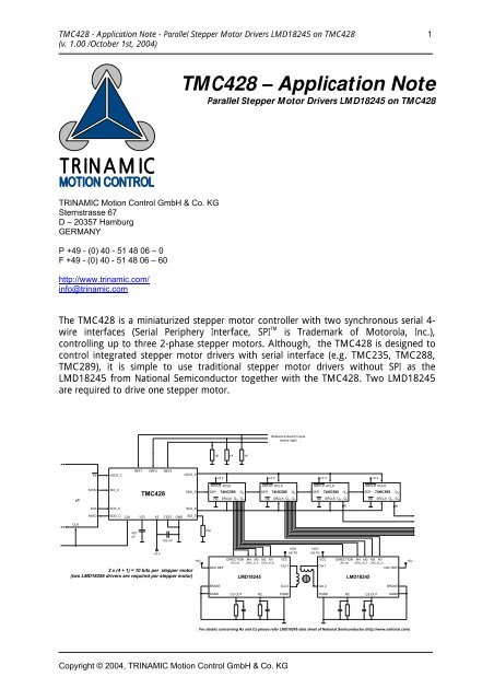
The <strong>TMC428</strong> is a miniaturized stepper motor controller with two synchronous serial 4-<br />
wire interfaces (Serial Periphery Interface, SPI TM<br />
is Trademark of Motorola, Inc.),<br />
controlling up to three 2-phase stepper motors. Although, the <strong>TMC428</strong> is designed to<br />
control integrated stepper motor drivers with serial interface (e.g. TMC235, TMC288,<br />
TMC289), it is simple to use traditional stepper motor drivers without SPI as the<br />
LMD18245 from National Semiconductor together with the <strong>TMC428</strong>. Two LMD18245<br />
are required to drive one stepper motor.<br />
Reference Switch Inputs<br />
(active high)<br />
1K<br />
1K<br />
1K<br />
SS<br />
nSCS_C<br />
REF1<br />
REF2<br />
REF3<br />
nSCS_S<br />
+5 V<br />
+5 V<br />
+5 V<br />
+5 V<br />
µC<br />
MOSI<br />
SDI_C<br />
<strong>TMC428</strong><br />
SDO_S<br />
SRCLR<br />
SER<br />
RCLK<br />
74HC595 Q H'<br />
OE SRCLK Q A ...Q H<br />
SRCLR<br />
SER<br />
OE<br />
RCLK<br />
74HC595<br />
SRCLK Q<br />
Q H'<br />
...Q A H<br />
SRCLR<br />
SER<br />
OE<br />
RCLK<br />
74HC595<br />
SRCLK Q<br />
Q H'<br />
...Q A H<br />
SRCLR<br />
SER<br />
OE<br />
RCLK<br />
74HC595<br />
SRCLK uQ Q H'<br />
...Q A H<br />
SCK<br />
SCK_C<br />
SCK_S<br />
8 8<br />
MISO<br />
SDO_C<br />
CLK<br />
V33<br />
V5<br />
TEST<br />
GND<br />
SDI_S<br />
CLK<br />
470<br />
nF<br />
100 nF<br />
10K<br />
+5 V<br />
+40V<br />
(up to)<br />
+40V<br />
(up to)<br />
2 x (4 + 1) = 10 bits per stepper motor<br />
(two LMD18256 drivers are required per stepper motor)<br />
+5V<br />
DIRECTION M4 M3 M2 M1<br />
(PH_A) (DAC_A_5 ... DAC_A_2)<br />
DAC REF<br />
LMD18245<br />
VCC<br />
Out 1<br />
VCC<br />
Out 1<br />
DIRECTION M4 M3 M2 M1<br />
(PH_B) (DAC_B_5 ... DAC_B_2)<br />
DAC REF<br />
LMD18245<br />
+5V<br />
BRAKE<br />
Out 2<br />
Out 2<br />
BRAKE<br />
SGND<br />
CS OUT<br />
RC<br />
PGND<br />
PGND<br />
RC<br />
CS OUT<br />
SGND<br />
For details concerning Rs and Cs please refer LMD18245 data sheet of National Semiconductor (http://www.national.<strong>com</strong>)<br />
Copyright © 2004, TRINAMIC Motion Control GmbH & Co. KG
<strong>TMC428</strong> - <strong>Application</strong> <strong>Note</strong> - Parallel Stepper Motor Drivers LMD18245 on <strong>TMC428</strong> 2<br />
(v. 1.00 /October 1st, 2004)<br />
Two chained 74HC595 are sufficient to form the SPI interface as required to control two<br />
LMD18245 by the <strong>TMC428</strong>. The 74HC595 contains an 8 bit shift register together with<br />
an 8 bit buffer register. The <strong>TMC428</strong> synchronously shifts stepper motor control bits<br />
(called primary signals within the <strong>TMC428</strong> data sheet) into the shift registers of the<br />
74HC595. After all control bits are transferred the content of the shift register is copied<br />
into the buffer register of the 74HC595. The content of the buffer registers is available<br />
in parallel. The primary signals of the <strong>TMC428</strong> enfold signals to control the phase<br />
current polarity, the DAC current amplitude, fast decay option, a constant 0 and a<br />
constant 1 signal, and a step and direction signal is available.<br />
The <strong>TMC428</strong> automatically updates the buffer register by sending an SPI datagram if<br />
necessary. So, the content of the buffer register of the 74HC595 is always up to date.<br />
For micro stepping two 4 bit digital-to-analog-converters (DACs) are integrated within<br />
the LMD18245 for current control.<br />
Once initialized, the <strong>TMC428</strong> generates all signals necessary to control up to three 2-<br />
phase stepper motors including velocity profiles. Simply writing a target position into the<br />
register associated to on stepper motor, causes the <strong>TMC428</strong> to move the stepper motor<br />
to that target position automatically taking motion parameter limits into account.<br />
Similar, a target velocity can be defined.<br />
The control signals (primary signals) generated by the <strong>TMC428</strong> are internally available in<br />
parallel. These control signals have to be available in parallel for the stepper motor<br />
driver. So, just the transmission of the stepper motor control signals from <strong>TMC428</strong> to<br />
the driver logic is serial. The datagram configuration defines the order of the signals.<br />
Each primary signal of the <strong>TMC428</strong> has its mnemonic and code. The sending order of<br />
primary signals is defined by the order of primary signals codes stored within the stepper<br />
motor driver datagram configuration RAM area (for details please refer the <strong>TMC428</strong><br />
data sheet). The order of control signals is individually programmable for each stepper<br />
motor driver. In case of this application note only one stepper motor is driven.<br />
The schematic shows the connections from the parallel outputs Qa, ..., Qh of the two<br />
74HC595 to the digital control inputs DIRECTION, M4, M3, M2, M1, DIRECTION, M4,<br />
M3 and M2, M1 of the two LMD18245. So, the serial stepper motor driver interface of<br />
the <strong>TMC428</strong> has to be configured that the primary signals map to the parallel outputs<br />
Qa, ..., Qh of the two 74HC595 which are mapped to the control signals of the two<br />
LMD18245. Within the following table, indices 1 an 2 are used to distinguish the<br />
outputs of the two 74HC595 and the inputs of the two LMD18245.<br />
Copyright © 2004, TRINAMIC Motion Control GmbH & Co. KG
<strong>TMC428</strong> - <strong>Application</strong> <strong>Note</strong> - Parallel Stepper Motor Drivers LMD18245 on <strong>TMC428</strong> 3<br />
(v. 1.00 /October 1st, 2004)<br />
The following table summarizes the mapping required:<br />
74HC595 LMD18245<br />
<strong>TMC428</strong><br />
primary signals primary codes<br />
Qa_1 DIRECTION PH_A $06<br />
Qb_1 M4 DAC_A_5 (MSB) $05<br />
Qc_1 M3 DAC_A_4 $04<br />
Qd_1 M2 DAC_A_3 $03<br />
Qe_1 M1 DAC_A_2 $02<br />
Qf_1 DIRECTION PH_B $0E<br />
Qg_1 M4 DAC_B_5 (MSB) $0D<br />
Qh_1 M3 DAC_B_4 $0C<br />
Qh_1‘<br />
Ser_2<br />
serial shift register output connected to<br />
serial shift register input of the 2 nd 74HC595<br />
Qa_2 M2 DAC_B_3 $0B<br />
Qb_2 M1 DAC_B_2 $0A<br />
Qc_2<br />
n.c.<br />
Qd_2<br />
Qe_2<br />
Qf_2<br />
Qg_2<br />
Qh_2<br />
Qh_2‘<br />
n.c.<br />
n.c.<br />
n.c.<br />
n.c.<br />
n.c.<br />
serial shift register output for connection of additional 74HC595<br />
The corresponding RAM configuration of the <strong>TMC428</strong> is:<br />
0A,0B,0C,0D,0E,02,03,04,05,26,00,00,00,00,00,00<br />
00,00,00,00,00,00,00,00,00,00,00,00,00,00,00,00<br />
00,00,00,00,00,00,00,00,00,00,00,00,00,00,00,00<br />
00,00,00,00,00,00,00,00,00,00,00,00,00,00,00,00<br />
00,01,03,04,06,07,09,0A,0C,0E,0F,11,12,14,15,17<br />
18,19,1B,1C,1E,1F,20,22,23,24,26,27,28,29,2A,2C<br />
2D,2E,2F,30,31,32,33,34,35,36,36,37,38,39,39,3A<br />
3B,3B,3C,3C,3D,3D,3E,3E,3E,3F,3F,3F,3F,3F,3F,3F<br />
Here, the upper 64 hexadecimal data words represent the configuration of the serial<br />
driver interface of the <strong>TMC428</strong>. The order of the primary signal codes<br />
($0A,$0B,$0C,$0D,$0E,$02,$03,$04,$05,$26) represents the order how the<br />
primary signals (DAC_B_2, DAC_B_3, DAC_B_4, DAC_B_5, PH_B, DAC_A_2, DAC_A_3, DAC_A_4,<br />
DAC_A_5, PH_A) are serially transferred to the 74HC595 shift register. These control<br />
signals are available at the parallel outputs (Qa_1, Qb_1, Qc_1, Qd_1, Qe_1, Qf_1,<br />
Qg_1, Qh_1, Qa_2, Qb_2) of the 74HC595. The value $26 (= $20 + $06) instead of<br />
$06 results from the so called NxM bit (Next Motor bit) which terminates a logical<br />
datagram block associated to one stepper motor driver. A datagram transmission is<br />
<strong>com</strong>plete if the control signals for all stepper motor drivers are sent. This is controlled by<br />
Copyright © 2004, TRINAMIC Motion Control GmbH & Co. KG
<strong>TMC428</strong> - <strong>Application</strong> <strong>Note</strong> - Parallel Stepper Motor Drivers LMD18245 on <strong>TMC428</strong> 4<br />
(v. 1.00 /October 1st, 2004)<br />
a <strong>TMC428</strong> parameter called LSMD (last stepper motor driver). The parameter LSMD has<br />
to be set 0 here for one stepper motor driver (please refer the <strong>TMC428</strong> data sheet for<br />
details).<br />
To transfer these 10 primary signal codes ($0A, $0B, $0C, $0D, $0E, $02,<br />
$03, $04, $05, $26) into the stepper motor driver configuration RAM area the<br />
micro controller has to sent 5 data 32 bit wide datagrams to <strong>TMC428</strong>. This is because<br />
two successive configuration RAM cells are <strong>com</strong>monly accessed. The datagrams to<br />
initialize the micro step look-up table (LUT) are described in detail within the <strong>TMC428</strong><br />
data sheet. The 5 datagrams for the serial stepper motor driver interface configuration<br />
are:<br />
$ 80 00 0B 0A<br />
$ 82 00 0D 0C<br />
$ 84 00 02 0E<br />
$ 86 00 04 03<br />
$ 88 00 26 05<br />
By chaining up to four 74HC595 one could control up to three LMD18245 stepper<br />
motor drivers. A <strong>com</strong>bination with SPI TM stepper motor drivers (e.g. TMC235, TMC288,<br />
TMC289) is also possible.<br />
The reference switch inputs REF1, REF2, REF3 are high active. So, with pull-up resistors,<br />
the reference switches have to be opening-switches. With pull-down resistors, the<br />
reference switches have to be closing-switches. The switches can be configured as<br />
automatic stop-switches (for details see <strong>TMC428</strong> data sheet).<br />
Literature<br />
• 74HC595 – Data Sheet, Texas Instruments,<br />
(on-line http://www.ti.<strong>com</strong>/)<br />
• LMD18245 – Data Sheet, National Semiconductor,<br />
(on-line http://www.national.<strong>com</strong>/)<br />
• <strong>TMC428</strong> – Data Sheet (v. 1.02 / November 22, 2001), TRINAMIC Microchips GmbH,<br />
(on-line http://www.trinamic.<strong>com</strong>/)<br />
Revision History<br />
Version Date Comment<br />
1.00 March 19, 2002 First <strong>com</strong>plete version published in printed form<br />
1.00 October 1 st , 2004 Changes concerning new <strong>com</strong>pany TRINAMIC Motion Control GmbH & Co. KG<br />
Please refer to www.trinamic.<strong>com</strong> for updated data sheets and application notes.<br />
The TMCtechLIB CD-ROM including data sheets, application notes, schematics of<br />
evaluation boards, software of evaluation boards, source code examples,<br />
parameter calculation spreadsheets, tools, and more is available from TRINAMIC<br />
Microchips GmbH by request to info@trinamic.<strong>com</strong><br />
Copyright © 2004, TRINAMIC Motion Control GmbH & Co. KG
<strong>TMC428</strong> - <strong>Application</strong> <strong>Note</strong> - Parallel Stepper Motor Drivers LMD18245 on <strong>TMC428</strong> 5<br />
(v. 1.00 /October 1st, 2004)<br />
Life support policy<br />
TRINAMIC Motion Control GmbH & Co. KG does not<br />
authorize or warrant any of its products for use in life<br />
support systems, without the specific written consent of<br />
TRINAMIC Motion Control GmbH & Co. KG.<br />
Life support systems are equipment intended to support or<br />
sustain life, and whose failure to perform, when properly<br />
used in accordance with instructions provided, can be<br />
reasonably expected to result in personal injury or death.<br />
Copyright © 2004, TRINAMIC Motion Control GmbH & Co. KG<br />
Information given in this application note is believed to be<br />
accurate and reliable. However no responsibility is assumed for<br />
the consequences of its use nor for any infringement of patents<br />
or other rights of third parties which may result form its use.<br />
Specifications subject to change without notice.<br />
Copyright © 2004, TRINAMIC Motion Control GmbH & Co. KG