Boot-Strap Loader - SemiconductorStore.com
Boot-Strap Loader - SemiconductorStore.com
Boot-Strap Loader - SemiconductorStore.com

You also want an ePaper? Increase the reach of your titles
YUMPU automatically turns print PDFs into web optimized ePapers that Google loves.
<strong>Boot</strong>-<strong>Strap</strong> <strong>Loader</strong><br />
MCU: v1.1F Firmware<br />
User’s Guide<br />
©2004 Silicon Storage Technology, Inc.<br />
S74006-00-000 9/04<br />
1<br />
The SST logo, SuperFlash, and FlashFlex are registered trademarks of Silicon Storage Technology, Inc.<br />
Intel is a registered trademark of Intel Corporation.<br />
These specifications are subject to change without notice.
<strong>Boot</strong>-<strong>Strap</strong> <strong>Loader</strong><br />
User’s Guide<br />
TABLE OF CONTENTS<br />
1.0 INTRODUCTION . . . . . . . . . . . . . . . . . . . . . . . . . . . . . . . . . . . . . . . . . . . . . . . . . . . . . . . . . . . . . . . . . . . . . . 3<br />
1.1 Scope . . . . . . . . . . . . . . . . . . . . . . . . . . . . . . . . . . . . . . . . . . . . . . . . . . . . . . . . . . . . . . . . . . . . . . . . . . . . 3<br />
1.2 Software/Documentation Updates . . . . . . . . . . . . . . . . . . . . . . . . . . . . . . . . . . . . . . . . . . . . . . . . . . . . . . 3<br />
1.3 EasyIAP Features . . . . . . . . . . . . . . . . . . . . . . . . . . . . . . . . . . . . . . . . . . . . . . . . . . . . . . . . . . . . . . . . . . 3<br />
2.0 HARDWARE REQUIREMENTS . . . . . . . . . . . . . . . . . . . . . . . . . . . . . . . . . . . . . . . . . . . . . . . . . . . . . . . . . . . 4<br />
2.1 Standard RS-232 Serial Cable. . . . . . . . . . . . . . . . . . . . . . . . . . . . . . . . . . . . . . . . . . . . . . . . . . . . . . . . . 4<br />
2.2 Hardware Connections. . . . . . . . . . . . . . . . . . . . . . . . . . . . . . . . . . . . . . . . . . . . . . . . . . . . . . . . . . . . . . . 4<br />
3.0 USING THE BOOT-STRAP LOADER . . . . . . . . . . . . . . . . . . . . . . . . . . . . . . . . . . . . . . . . . . . . . . . . . . . . . . 5<br />
3.1 Self-detection of Serial Link . . . . . . . . . . . . . . . . . . . . . . . . . . . . . . . . . . . . . . . . . . . . . . . . . . . . . . . . . . . 5<br />
3.2 Menus . . . . . . . . . . . . . . . . . . . . . . . . . . . . . . . . . . . . . . . . . . . . . . . . . . . . . . . . . . . . . . . . . . . . . . . . . . . 5<br />
3.2.1 File . . . . . . . . . . . . . . . . . . . . . . . . . . . . . . . . . . . . . . . . . . . . . . . . . . . . . . . . . . . . . . . . . . . . . . . . . 5<br />
3.2.2 Detect Chip/RS-232 Menu . . . . . . . . . . . . . . . . . . . . . . . . . . . . . . . . . . . . . . . . . . . . . . . . . . . . . . . 6<br />
3.2.3 RunCode . . . . . . . . . . . . . . . . . . . . . . . . . . . . . . . . . . . . . . . . . . . . . . . . . . . . . . . . . . . . . . . . . . . . 7<br />
3.2.4 ByteModify . . . . . . . . . . . . . . . . . . . . . . . . . . . . . . . . . . . . . . . . . . . . . . . . . . . . . . . . . . . . . . . . . . . 8<br />
3.2.5 SoftICE. . . . . . . . . . . . . . . . . . . . . . . . . . . . . . . . . . . . . . . . . . . . . . . . . . . . . . . . . . . . . . . . . . . . . . 8<br />
3.3 Toolbar Buttons . . . . . . . . . . . . . . . . . . . . . . . . . . . . . . . . . . . . . . . . . . . . . . . . . . . . . . . . . . . . . . . . . . . . 9<br />
3.3.1 RESET - Reset Target MCU/Clear Chip Info . . . . . . . . . . . . . . . . . . . . . . . . . . . . . . . . . . . . . . . . . 9<br />
3.3.2 2xCLK - Double Clock . . . . . . . . . . . . . . . . . . . . . . . . . . . . . . . . . . . . . . . . . . . . . . . . . . . . . . . . . . 9<br />
3.4 IAP Functions. . . . . . . . . . . . . . . . . . . . . . . . . . . . . . . . . . . . . . . . . . . . . . . . . . . . . . . . . . . . . . . . . . . . . 10<br />
3.4.1 Download . . . . . . . . . . . . . . . . . . . . . . . . . . . . . . . . . . . . . . . . . . . . . . . . . . . . . . . . . . . . . . . . . . . 10<br />
3.4.2 Download/Run User Code . . . . . . . . . . . . . . . . . . . . . . . . . . . . . . . . . . . . . . . . . . . . . . . . . . . . . . 10<br />
3.4.3 Read. . . . . . . . . . . . . . . . . . . . . . . . . . . . . . . . . . . . . . . . . . . . . . . . . . . . . . . . . . . . . . . . . . . . . . . 10<br />
3.4.4 Sector Erase. . . . . . . . . . . . . . . . . . . . . . . . . . . . . . . . . . . . . . . . . . . . . . . . . . . . . . . . . . . . . . . . . 10<br />
3.4.5 Chip Erase . . . . . . . . . . . . . . . . . . . . . . . . . . . . . . . . . . . . . . . . . . . . . . . . . . . . . . . . . . . . . . . . . . 10<br />
3.4.6 Lock Chip . . . . . . . . . . . . . . . . . . . . . . . . . . . . . . . . . . . . . . . . . . . . . . . . . . . . . . . . . . . . . . . . . . . 10<br />
3.4.7 Memory Remap . . . . . . . . . . . . . . . . . . . . . . . . . . . . . . . . . . . . . . . . . . . . . . . . . . . . . . . . . . . . . . 10<br />
4.0 INSTALLING WINDOWS SOFTWARE . . . . . . . . . . . . . . . . . . . . . . . . . . . . . . . . . . . . . . . . . . . . . . . . . . . . 11<br />
APPENDIX A: LIST OF SOURCE CODE . . . . . . . . . . . . . . . . . . . . . . . . . . . . . . . . . . . . . . . . . . . . . . . . . . . . . . . 13<br />
APPENDIX B: BSL DEMO BOARD VER.2.0 SWITCH FUNCTIONS. . . . . . . . . . . . . . . . . . . . . . . . . . . . . . . . . . 14<br />
APPENDIX C: BSL DEMO BOARD VER.2.0 SCHEMATIC . . . . . . . . . . . . . . . . . . . . . . . . . . . . . . . . . . . . . . . . . 15<br />
APPENDIX D: SST STARTER KIT V3.0 SWITCH FUNCTION . . . . . . . . . . . . . . . . . . . . . . . . . . . . . . . . . . . . . . 16<br />
©2004 Silicon Storage Technology, Inc. S74006-00-000 9/04<br />
2
<strong>Boot</strong>-<strong>Strap</strong> <strong>Loader</strong><br />
User’s Guide<br />
1.0 INTRODUCTION<br />
The <strong>Boot</strong>-<strong>Strap</strong> <strong>Loader</strong> (BSL) software enables SST customers to download/upload their application software into/<br />
from the FlashFlex51 flash memory via In-Application Programming 1 (IAP) while the system is running. The PC<br />
executable, SSTEasyIAP.exe, is a Windows-based application and the MCU version 1.1F firmware is for 8051-family<br />
MCUs.<br />
The purpose of this document is to provide a hands-on reference guide for the users. It also helps the users see a<br />
clear picture of the system connections and the EasyIAP11F <strong>Boot</strong>-<strong>Strap</strong> <strong>Loader</strong> features.<br />
1.1 Scope<br />
The scope of this document is limited to the features of the EasyIAP11F <strong>Boot</strong>-<strong>Strap</strong> <strong>Loader</strong> and target hardware<br />
requirements.<br />
1.2 Software/Documentation Updates<br />
The latest versions of the BSL firmware, the EasyIAP software and documentation are available for download from<br />
the SST web site at www.sst.<strong>com</strong> or www.SuperFlash.<strong>com</strong>.<br />
• For the latest Keil software and documentation updates, visit Keil’s web site at www.keil.<strong>com</strong>.<br />
• For technical support via email, please contact the SST FlashFlex51 product Hot Line: Support@sst.<strong>com</strong>.<br />
1.3 EasyIAP Features<br />
Firmware features implemented in the BSL v1.1F include:<br />
• Pre-programmed into SST89E/V5x4Rx and SST89E/V5xRDx MCUs<br />
• Support for SST89C54/58 MCUs<br />
• Read<br />
• Download<br />
• Sector Erase<br />
• Run User Code<br />
• Chip Erase<br />
• Chip Remap<br />
• Lock Chip<br />
• File Compare<br />
• File Save<br />
• File Print<br />
• Byte-Modify<br />
• Auto-baud rate detection<br />
• BSL upgrade capability<br />
• Download SoftICE<br />
• Selectable BSL v1.1E to v1.1F upgrade capability<br />
• File download and upload capability from either internal or external memory<br />
• Lock Chip in internal memory mode for SST89E/V5x4Rx and SST89E/V5xRDx<br />
• Program SC0, SC1 bit for SST89E/V5x4Rx and SST89E/V5xRDx<br />
• Double Clock function for SST89E/V5x4Rx and SST89E/V5xRDx<br />
• PC controls EA# and RST with BSL demo board 2.0 and later versions<br />
1. The <strong>Boot</strong>-<strong>Strap</strong> <strong>Loader</strong> Software Example is for the user’s reference and convenience only.<br />
SST does not guarantee the functionality or the usefulness of the example bootstrap loader.<br />
©2004 Silicon Storage Technology, Inc. S74006-00-000 9/04<br />
3
<strong>Boot</strong>-<strong>Strap</strong> <strong>Loader</strong><br />
User’s Guide<br />
2.0 HARDWARE REQUIREMENTS<br />
• RS-232 Serial Cable<br />
• Down <strong>Loader</strong> Kit<br />
2.1 Standard RS-232 Serial Cable<br />
A standard RS-232 DTE-DCE cable is required to connect the host PC to the development platform. The female<br />
end of the cable connects to the PC (Data Terminal Equipment, DTE) and the male end connects to the development<br />
platform (Data Communication Equipment, DCE).<br />
The serial cable connections are:<br />
PC DB-9 plug (COM1 or COM2) Development Platform<br />
RxD Pin 2 to TxD Pin 2<br />
TxD Pin 3 to RxD Pin 3<br />
DTR Pin 4 to DTR Pin 4<br />
GND Pin 5 to GND Pin 5<br />
RTS Pin 7 to RTS Pin 7<br />
No hardware handshake line is required to invoke <strong>com</strong>munication between the host PC and the development platform<br />
as the firmware contains a transmission protocol to ensure fault-free data transmission between the PC and<br />
the development platform.<br />
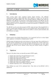
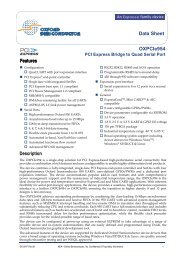
2.2 Hardware Connections<br />
The PC should be connected to the target board through a standard RS-232 cable as shown in the figure below.<br />
PC<br />
SST89C5x<br />
SST89E/V5x4Rx<br />
SST89E/V5xxRDx<br />
Target Board<br />
EasyIAP<br />
Software<br />
BSL<br />
Firmware<br />
GND<br />
TXD<br />
RXD<br />
RS-232<br />
XCVR<br />
GND<br />
RXD<br />
TXD<br />
SST Download<br />
4006 F01.0<br />
©2004 Silicon Storage Technology, Inc. S74006-00-000 9/04<br />
4
<strong>Boot</strong>-<strong>Strap</strong> <strong>Loader</strong><br />
User’s Guide<br />
3.0 USING THE BOOT-STRAP LOADER<br />
The following figure shows the entry window of the EasyIAP11F <strong>Boot</strong>-<strong>Strap</strong> <strong>Loader</strong>.<br />
3.1 Self-detection of Serial Link<br />
The software can detect whether the serial link is alive or not in about ten seconds. After either a disconnection of<br />
the serial link or an interruption of DC power, the software issues a warning message and clears the chip information<br />
on the screen.<br />
3.2 Menus<br />
3.2.1 File<br />
From this option, user can select Compare, Save and Print options.<br />
3.2.1.1 Compare<br />
This option <strong>com</strong>pares an Intel hex or a binary file with the contents in internal (block 0/1) or external (low/high 64K)<br />
flashes memory. Enter or select a filename, select the starting address (in Range list box), then click OK. The<br />
result of the <strong>com</strong>parison is shown in the dialog box (labeled as IAP Status) – the text of “File Compare OK!” is for a<br />
matched <strong>com</strong>parison or the text of “Unmatched data at memory address xxxxH: xxH(MCU) vs. xxH(File)” is for<br />
unmatched <strong>com</strong>parison.<br />
3.2.1.2 Save Data into a File (Upload)<br />
This option saves the contents of block 0/1 of internal flash or low/high 64K of external flash into a binary/text file.<br />
Enter a filename, choose the type of file (binary or text file), select the starting address and number of sectors (in<br />
Range list box), and then clicks OK. Click OK when the message “Save data has <strong>com</strong>pleted” appears.<br />
3.2.1.3 Print Memory Contents<br />
The Print option sends memory data from internal or external flash to a printer.<br />
©2004 Silicon Storage Technology, Inc. S74006-00-000 9/04<br />
5
<strong>Boot</strong>-<strong>Strap</strong> <strong>Loader</strong><br />
User’s Guide<br />
3.2.2 Detect Chip/RS-232 Menu<br />
This option allows user to select firmware version. Click Select Chip/RS-232 to display the firmware choices.<br />
3.2.2.1 Detect Target MCU for Firmware1.1F and RS232 Config<br />
Clicking this option selects the latest firmware version, 1.1F, and opens the following window. Choose the correct<br />
Chip Type and Memory Mode then click OK.<br />
The next window displays the default values for the Comm Port and Baud Rate.<br />
Select the COM# used to connect the serial cable to the PC. Then enter the crystal frequency of the target MCU<br />
and click Compute to calculate the “best” baud rate. Clicking Next Baud will calculate the 2nd, 3rd, 4th next-best<br />
baud rates. Then click Detect MCU.<br />
©2004 Silicon Storage Technology, Inc. S74006-00-000 9/04<br />
6
<strong>Boot</strong>-<strong>Strap</strong> <strong>Loader</strong><br />
User’s Guide<br />
Once the chip is detected successfully, the target MCU information will display in the upper right-hand corner. If an<br />
error message appears, please check the physical Comm Port connection and repeat the steps to detect the chip<br />
beginning in Section 3.2.2, “Detect Chip/RS-232 Menu” on page 6.<br />
The RS-232 configuration is saved into a text file, SstBslComDft.txt, at the root directory of C drive. This saved configuration<br />
be<strong>com</strong>es the future default.<br />
3.2.2.2 Detect Target MCU for Firmware1.1E and Upgrade to 1.1F (EA# =1)<br />
Clicking this option causes the software to search for firmware version 1.1E in internal memory. If the software<br />
detects firmware version 1.1E it upgrades it to version 1.1F automatically without destroying the user’s code in<br />
block 0. This function can only be used in Internal Memory Mode.<br />
3.2.2.3 Detect Target MCU for firmware version is unknown (EA# =1)<br />
Choose this option if the firmware version is unknown.<br />
Clicking this option causes the software to search internal memory for firmware version 1.1F first, if that fails, it<br />
searches for version 1.1E. If version 1.1E is detected, it is automatically upgraded to version 1.1F without destroying<br />
the user’s code in block 0. This function can only be used in Internal Memory Mode.<br />
3.2.3 RunCode<br />
This function executes user code at address 0000H in block 0 of the internal flash memory.<br />
©2004 Silicon Storage Technology, Inc. S74006-00-000 9/04<br />
7
<strong>Boot</strong>-<strong>Strap</strong> <strong>Loader</strong><br />
User’s Guide<br />
3.2.4 ByteModify<br />
Click on Help and About Byte Modify to view a brief description of this option.<br />
This option allows the contents of block 0 to be modified. To do this, enter a 4-digit memory location in hexadecimal<br />
format into the first field and click Display Data. The second field displays up to sixteen bytes of data starting from<br />
the address entered.<br />
Enter up to sixteen bytes of new data into the lowest field. Separate each byte with a single space and click<br />
Replace Data to <strong>com</strong>plete the data modification.<br />
3.2.5 SoftICE<br />
3.2.5.1 Download SoftICE<br />
SoftICE (Software In-Circuit Emulator) is an in-circuit development tool used to debug applications for SST89C5x,<br />
SST89x5x4Rx, and SST89x5xxRDx MCUs. SoftICE will download to the first 1K in block 1 and the last 4K in block<br />
0 (for SST89C5x), or the first 4K in block 1 and the last 1K in block 0 (for SST89x5x4Rx and SST89x5xRDx).<br />
Please note that downloading SoftICE will erase the BSL loaded in block 1.<br />
Refer to the SoftICE User Guide for detailed information and instructions.<br />
©2004 Silicon Storage Technology, Inc. S74006-00-000 9/04<br />
8
<strong>Boot</strong>-<strong>Strap</strong> <strong>Loader</strong><br />
User’s Guide<br />
3.3 Toolbar Buttons<br />
3.3.1 RESET - Reset Target MCU/Clear Chip Info<br />
Clicking on the yellow RESET toolbar button erases the Chip Information on the screen and sends a RTS and DTR<br />
signal to the target MCU through the RS232 serial port.<br />
The RTS/DTR signal provides a single level with standard RS232 signal amplitude (from -12 V to +12V). The duration<br />
of RTS signal is about 40 milliseconds before it rises from -12V to +12V. On the target MCU board, the user<br />
can optionally transform this RTS signal into a +5V signal and uses it to reset the target MCU.<br />
3.3.2 2xCLK - Double Clock<br />
This feature applies to SST89x5x4Rx and SST89x5xRDx only, the crystal frequency of the target board will be doubled<br />
by clicking this button.<br />
©2004 Silicon Storage Technology, Inc. S74006-00-000 9/04<br />
9
<strong>Boot</strong>-<strong>Strap</strong> <strong>Loader</strong><br />
User’s Guide<br />
3.4 IAP Functions<br />
3.4.1 Download<br />
User code can only be downloaded into block 0 of the MCUs internal flash or the low/high 64K of external<br />
flash. To start downloading, click Download under IAP Function, enter the appropriate File Name, e.g.<br />
BINCTR.HEX, and Starting Sector (e.g. 0000H), then click on OK.<br />
Prior to downloading, the sectors in flash memory, which match the code size, are erased <strong>com</strong>pletely. Consequently,<br />
the program warns the user and asks whether the download is to proceed or not. Click Yes to proceed or<br />
No to quit. To search for the file, the user can click Browse located at the right side of File Name list box.<br />
3.4.2 Download/Run User Code<br />
This function <strong>com</strong>bines Download and Run User Code into one. The Download/Run-User-Code <strong>com</strong>mand automatically<br />
runs user code after reprogramming block 0 of the flash memory.<br />
3.4.3 Read<br />
This function reads the code from either block 0 or block 1 flash memory, and then displays the contents in hex format.<br />
The procedure is:<br />
1. Click Read<br />
2. Select the starting address and range of sectors<br />
3. Click OK.<br />
Sector status can be any one of three conditions – Blank, Not Blank or Unknown. The content of an unread sector<br />
which shows all 00s corresponds to the All Zeros status.<br />
3.4.4 Sector Erase<br />
This option enables the user to select the region of internal/external flash memory to be erased. The user enters<br />
the starting address and number of sectors (in Range list box) to be erased, then clicks OK. Click OK when the<br />
message “Sector erase <strong>com</strong>pleted!” appears.<br />
3.4.5 Chip Erase<br />
This option is only allowed in External Memory Mode.<br />
3.4.6 Lock Chip<br />
Most lock levels are allowed in External Memory Mode for C54/C58.<br />
All lock levels are allowed in Internal Memory Mode for SST89E/V5x4Rx and SST89E/V5xRDx.<br />
3.4.7 Memory Remap<br />
This option is only allowed in External Memory Mode. Users can choose to remap to 1K, 2K, and 4K for<br />
SST89C5x. For SST89x564RD, user can program SC0, and for SST89x554RC and SST89x5xRDx, users can<br />
choose to program SC0 and SC1.<br />
©2004 Silicon Storage Technology, Inc. S74006-00-000 9/04<br />
10
<strong>Boot</strong>-<strong>Strap</strong> <strong>Loader</strong><br />
User’s Guide<br />
4.0 INSTALLING WINDOWS SOFTWARE<br />
The BSL package includes a PC executable program and the MCU binary/Intel Hex code. The PC executable,<br />
SSTEasyIAP.EXE, is a Window-based application and runs directly under Windows 95/98/NT/2000/Me/XP operating<br />
systems. Two additional MFC library files provided in this package, MFC42.DLL and MSVCRT.DLL, are usually<br />
located in the Windows System or System32 folder. The user needs to copy these two library files into the same<br />
folder as SSTEasyIAP.EXE only if they don’t exist or are not the latest revision codes.<br />
The MCU binary/Intel Hex code can work with external crystal frequency range from 1 MHz through 33 MHz (40<br />
MHz for SST89E5x4Rx and SST89E5xRDx), the PC pre-settings for serial <strong>com</strong>munication are: 38.4K/19.2K/9600/<br />
4800/2400/1200/600 baud, 8 data bits, 1 stop bit, and no parity.<br />
The MCU code, residing in block 1 flash, can be installed in three different ways:<br />
1. by the factory,<br />
2. by the user with SST <strong>Boot</strong>-<strong>Strap</strong> <strong>Loader</strong> (BSL) Demo Kit,<br />
3. by the user with a universal programmer that supports the SST microcontroller.<br />
Please visit the SST website for the information on the SST BSL Demo Kit, and the list of programmer vendors that<br />
support the FlashFlex51 family.<br />
©2004 Silicon Storage Technology, Inc. S74006-00-000 9/04<br />
11
<strong>Boot</strong>-<strong>Strap</strong> <strong>Loader</strong><br />
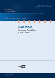
User’s Guide<br />
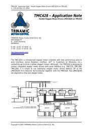
Reset or Switch from User Code to<br />
BSL v1.1F(MCU Firmware)<br />
No<br />
Is<br />
Chip Re-mapped<br />
?<br />
Yes<br />
No<br />
Is<br />
WDT Timeout<br />
?<br />
Yes<br />
Start the baud-rate<br />
detection routine by<br />
evaluating the test<br />
string sent by host PC<br />
Run User Code<br />
Yes<br />
Is<br />
detection failed<br />
?<br />
No<br />
Disable WDT<br />
Execute IAP*<br />
Operations<br />
FIGURE<br />
4-1: MCU FIRMWARE ARCHITECTURE OF BOOT-STRAP LOADER V1.1F<br />
©2004 Silicon Storage Technology, Inc. S74006-00-000 9/04<br />
12
<strong>Boot</strong>-<strong>Strap</strong> <strong>Loader</strong><br />
User’s Guide<br />
APPENDIX A. LIST OF SOURCE CODE<br />
The BSL package consists of three parts:<br />
• For the Windows 95/98/NT/2000/Me/XP-resident software, an executable file (SSTEasyIAP11.EXE) is supplied.<br />
• For the MCU-resident code, an Intel hex file (.HEX) and a binary file (.BIN) are furnished.<br />
• For the external memory-resident code, an Intel hex file (.HEX) is furnished.<br />
Table A-1 lists the files that can be downloaded from the SST web site. Both Internal Memory Mode and External<br />
Memory Mode versions use MCU Timer 2 for baud rate generation for the serial port.<br />
TABLE A-1: LIST OF EASYIAP11F (PC) / BSL V1.1F (MCU) / V1.1F (EXTERNAL MEMORY CHIP) FILES<br />
Chip Type Ext. Crystal Frequency Baud Rate PC Files MCU/Ext. Memory Files<br />
SST89C54/C58<br />
(Internal Memory Mode)<br />
SST89E/V554RC<br />
(Internal Memory Mode)<br />
SST89E/V564RD<br />
(Internal Memory Mode)<br />
SST89E/V58RD2<br />
(Internal Memory Mode)<br />
SST89E/V54RD2<br />
(Internal Memory Mode)<br />
SST89E/V516RD2<br />
(Internal Memory Mode)<br />
SST39SF010A MPF<br />
or equivalent Flash Memory<br />
(External Memory Mode)<br />
1 – 33 MHz (5V)<br />
1 – 12 MHz (2.7V)<br />
1 – 33 MHz (V554RC)<br />
1 – 40 MHz (E554RC)<br />
1 – 33 MHz (V564RD)<br />
1 – 40 MHz (E564RD)<br />
1 – 33 MHz (V58RD2)<br />
1 – 40 MHz (E58RD2)<br />
1 – 33 MHz (V54RD2)<br />
1 – 40 MHz (E54RD2)<br />
1 – 33 MHz (V516RD2)<br />
1 – 40 MHz (E516RD2)<br />
N/A<br />
38.4K/19.2K/9.6K/<br />
4.8K/2.4K/1.2K/600<br />
38.4K/19.2K/9.6K/<br />
4.8K/2.4K/1.2K/600<br />
38.4K/19.2K/9.6K/<br />
4.8K/2.4K/1.2K/600<br />
38.4K/19.2K/9.6K/<br />
4.8K/2.4K/1.2K/600<br />
38.4K/19.2K/9.6K/<br />
4.8K/2.4K/1.2K/600<br />
38.4K/19.2K/9.6K/<br />
4.8K/2.4K/1.2K/600<br />
38.4K/19.2K/9.6K/<br />
4.8K/2.4K/1.2K/600<br />
SSTEasyIAP11F.exe F51MBLI5.HEX 1<br />
F51MBLI5.BIN 1<br />
SSTEasyIAP11F.exe F51MBLL5.BIN 1<br />
SSTEasyIAP11F.exe F51MBLL5.BIN 2<br />
SSTEasyIAP11F.exe F51MBLL5.BIN 1<br />
SSTEasyIAP11F.exe F51MBLL5.BIN 1<br />
SSTEasyIAP11F.exe F51MBLL5.BIN 2<br />
SSTEasyIAP11F.exe F51EBLK5.HEX<br />
TA-1.1 4006<br />
1. Binary file should be downloaded into block 1 and starts at address F000H for SST89C5x and E000H for SST89x554RC and<br />
SST89x54/58RD2. The hex file needs to be downloaded into block 0 and starts at address 0000H.<br />
2. Both binary file and hex file should be downloaded to address 0000H of block 1 for SST89x564RD and SST89x516RD2.<br />
©2004 Silicon Storage Technology, Inc. S74006-00-000 9/04<br />
13
<strong>Boot</strong>-<strong>Strap</strong> <strong>Loader</strong><br />
User’s Guide<br />
APPENDIX B. BSL DEMO BOARD VER.2.0 SWITCH FUNCTIONS<br />
TABLE<br />
B-1: FUNCTIONS OF INDIVIDUAL SWITCHES ON BSL DEMO BOARD (V2.0)<br />
Position Function<br />
1 EA1 OFF=1 See Table B-2 and Table B-3 below<br />
ON=0<br />
2 CE# OFF=1 Disable External Flash SST39SF010A<br />
ON=0 Enable on-board SST39SF010A<br />
3 A16 OFF=1 Select upper 64K of SST39SF010A<br />
ON=0 Select lower 64K of SST39SF010A<br />
4 P3.2 OFF=1 User definable switch’s function<br />
5 P3.3 ON=0<br />
6 P3.4<br />
7 P3.5<br />
8 RST1 OFF RST is controlled by PC software<br />
ON RST is controlled by MAX706 with Manual Reset button<br />
TABLE<br />
B-2: BSL DEMO BOARD RUNNING STAND-ALONE WITHOUT PC CONTROL:<br />
NOTE: Disconnect cable between PC and Board v2.0<br />
RST1 must be ON, MCU’s RST is controlled by on board MAX706 with Manual Reset button<br />
EA1 A16 CE# Effects<br />
0 0 0 Run external lower 64K of SST39SF010A<br />
0 1 0 Run external upper 64K of SST39SF010A<br />
1 0 0 Run internally, lower 64K as data memory<br />
1 1 0 Run internally, upper 64K as data memory<br />
0 0 1 Illegal <strong>com</strong>bination of settings<br />
0 1 1 Illegal <strong>com</strong>bination of settings<br />
1 0 1 Run internally, no data memory, SST39SF010A is disabled<br />
1 1 1 Run internally, no data memory, SST39SF010A is disabled<br />
TABLE B-3: BSL DEMO BOARD RUNNING UNDER CONTROL OF PC SOFTWARE:<br />
Both RST1 and EA1 must be set OFF, MCU’s RST and EA# is controlled by PC software<br />
RST2<br />
1 Reset MCU, don’t care EA2, A16 or CE#.<br />
0 MCU is running, mode is determined by following chart:<br />
EA2 A16 CE# Effects<br />
0 0 0 Run external lower 64K of SST39SF010A<br />
0 1 0 Run external upper 64K of SST39SF010A<br />
1 0 0 Run internally, lower 64K as data memory<br />
1 1 0 Run internally, upper 64K as data memory<br />
0 0 1 Illegal <strong>com</strong>bination of settings<br />
0 1 1 Illegal <strong>com</strong>bination of settings<br />
1 0 1 Run internally, no data memory, SST39SF010A is disabled<br />
1 1 1 Run internally, no data memory, SST39SF010A is disabled<br />
TB-1.0 4006<br />
TB-2.0 4006<br />
TB-3.0 4006<br />
©2004 Silicon Storage Technology, Inc. S74006-00-000 9/04<br />
14
<strong>Boot</strong>-<strong>Strap</strong> <strong>Loader</strong><br />
User’s Guide<br />
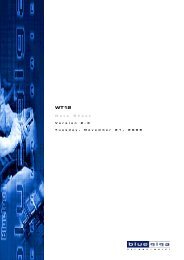
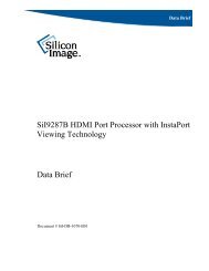
APPENDIX C. BSL DEMO BOARD VER.2.0 SCHEMATIC<br />
POWER IN<br />
8 - 12 VDC<br />
VDD C4 47uF<br />
AD[0:7]<br />
P1.0<br />
P1.1<br />
P1.2<br />
P1.3<br />
P1.4<br />
P1.5<br />
P1.6<br />
P1.7<br />
RST<br />
RXD P3.0<br />
TXD P3.1<br />
P3.2<br />
P3.3<br />
P3.4<br />
P3.5<br />
P3.6<br />
P3.7<br />
XTAL2<br />
XTAL1<br />
C3<br />
0.1uF<br />
P0.0 AD0<br />
AD0<br />
P0.1 AD1<br />
AD1<br />
P0.2 AD2<br />
AD2<br />
P0.3 AD3<br />
AD3<br />
P0.4 AD4<br />
AD4<br />
P0.5 AD5<br />
AD5<br />
P0.6 AD6<br />
AD6<br />
P0.7 AD7<br />
AD7<br />
EA#<br />
ALE ALE<br />
PSEN<br />
P2.7 A15<br />
P2.6 A14<br />
P2.5 A13<br />
P2.4 A12<br />
P2.3 A11<br />
P2.2 A10<br />
P2.1 A9<br />
P2.0 A8<br />
A[0:15]<br />
A0<br />
A1<br />
A2<br />
A3<br />
A4<br />
A5<br />
A6<br />
A7<br />
VDD<br />
A0<br />
A1<br />
A2<br />
A3<br />
A4<br />
A5<br />
A6<br />
A7<br />
A8<br />
A9<br />
A10<br />
A11<br />
A12<br />
A13<br />
A14<br />
A15<br />
CE#<br />
OE#<br />
WR<br />
AD0<br />
AD1<br />
AD2<br />
AD3<br />
AD4<br />
AD5<br />
AD6<br />
AD7<br />
A0<br />
A1<br />
A2<br />
A3<br />
A4<br />
A5<br />
A6<br />
A7<br />
P1.0<br />
P1.1<br />
P1.2<br />
P1.3<br />
P1.4<br />
P1.5<br />
P1.6<br />
P1.7<br />
RST<br />
P3.0<br />
P3.1<br />
P3.2<br />
P3.3<br />
P3.4<br />
P3.5<br />
P3.6<br />
P3.7<br />
XTAL2<br />
XTAL1<br />
GND<br />
P0.0<br />
P0.1<br />
P0.2<br />
P0.3<br />
P0.4<br />
P0.5<br />
P0.6<br />
P0.7<br />
EA#<br />
ALE<br />
PSEN<br />
P2.7<br />
P2.6<br />
P2.5<br />
P2.4<br />
P2.3<br />
P2.2<br />
P2.1<br />
P2.0<br />
A16<br />
ALE<br />
10<br />
9<br />
8<br />
7<br />
6<br />
5<br />
4<br />
VDD<br />
3<br />
1 2<br />
RP1 330 Ohm, SIP10<br />
RST2 12<br />
RST1 13<br />
VDD<br />
VDD<br />
RX<br />
TX<br />
DTR<br />
RTS<br />
TXD<br />
11 RST<br />
C2<br />
27pF<br />
VDD<br />
C<br />
VDD<br />
EA2<br />
EA1<br />
EA#<br />
PSEN<br />
RD<br />
VDD<br />
OE#<br />
VDD<br />
D1 1N4001<br />
D2 1N4001<br />
C11<br />
0.1uF<br />
R2<br />
300<br />
C13<br />
0.1uF<br />
VDD<br />
MANUAL RESET<br />
VDD<br />
2<br />
VCC RST<br />
7<br />
3<br />
6<br />
C7<br />
GND ST<br />
0.1uF 4<br />
IN NMI<br />
5<br />
MAX706PCSA<br />
Note: 1. all capacitors are 16V rating<br />
2. 1.25V < VDD < 5.5V<br />
3. 0.5MHz < Crystal Frequency < 40MHz<br />
4. Erase & Program U3 ONLY when VDD>=3.3V<br />
Title<br />
SST FlashFlex51 BOOTSTRAP LOADER DEMO BOARD<br />
Size Document Number Rev<br />
SST BSL Demo V2.0 1.0<br />
Friday, March 08, 2002<br />
Date: Sheet of 1 1<br />
C<br />
JP1<br />
1 2<br />
3 4<br />
5 6<br />
7 8<br />
9 10<br />
11 12<br />
13 14<br />
15 16<br />
17 18<br />
19 20<br />
21 22<br />
23 24<br />
25 26<br />
27 28<br />
29 30<br />
31 32<br />
33 34<br />
35 36<br />
37 38<br />
39 40<br />
HEADER 20X2<br />
RP2 10K, SIP 10<br />
2<br />
3<br />
4<br />
5<br />
6<br />
7<br />
8<br />
9<br />
10<br />
1<br />
P10<br />
P11<br />
P12<br />
P13<br />
D3<br />
POWER ON<br />
P14<br />
P15<br />
P16<br />
P17<br />
U6<br />
C1+ OFF<br />
V+ VCC<br />
C1- GND<br />
C2+ T1OUT<br />
C2- T2OUT<br />
V- T3OUT<br />
T1IN R1IN<br />
T2IN R2IN<br />
INVALID R3IN<br />
T3IN VL<br />
ON R1OUT<br />
R3OUT R2OUT<br />
MAX3387E<br />
R1<br />
100 Ohm<br />
1<br />
2<br />
3<br />
4<br />
5<br />
6<br />
7<br />
8<br />
9<br />
10<br />
11<br />
12<br />
13<br />
14<br />
15<br />
16<br />
17<br />
18<br />
19<br />
20<br />
U1<br />
P1.0<br />
P1.1<br />
P1.2<br />
P1.3<br />
P1.4<br />
P1.5<br />
P1.6<br />
P1.7<br />
RST<br />
P3.0/RXD<br />
P3.1/TXD<br />
P3.2/INT0#<br />
P3.3/INT1#<br />
P3.4/T0<br />
P3.5/T1<br />
P3.6/WR#<br />
P3.7/RD#<br />
XTAL2<br />
XTAL1<br />
Vss<br />
VDD<br />
P0.0/AD0<br />
P0.1/AD1<br />
P0.2/AD2<br />
P0.3/AD3<br />
P0.4/AD4<br />
P0.5/AD5<br />
P0.6/AD6<br />
P0.7/AD7<br />
EA#<br />
ALE/PROG#<br />
PSEN#<br />
P2.7/A15<br />
P2.6/A14<br />
P2.5/A13<br />
P2.4/A12<br />
P2.3/A11<br />
P2.2/A10<br />
P2.1/A9<br />
P2.0/A8<br />
40<br />
39<br />
38<br />
37<br />
36<br />
35<br />
34<br />
33<br />
32<br />
31<br />
30<br />
29<br />
28<br />
27<br />
26<br />
25<br />
24<br />
23<br />
22<br />
21<br />
SST FlashFlex51 PDIP Socket<br />
C5<br />
0.1uF<br />
U3<br />
20<br />
A0 DQ0<br />
21<br />
19<br />
A1 DQ1<br />
22<br />
18<br />
A2 DQ2<br />
23<br />
17<br />
A3 DQ3<br />
25<br />
16<br />
A4 DQ4<br />
26<br />
15<br />
A5 DQ5<br />
27<br />
14<br />
A6 DQ6<br />
28<br />
13<br />
A7 DQ7<br />
29<br />
3<br />
A8<br />
2<br />
A9 NC2<br />
9<br />
31<br />
A10<br />
1<br />
A11 NC1<br />
6<br />
12<br />
A12<br />
4<br />
A13 A16<br />
10<br />
5<br />
A14<br />
11<br />
A15<br />
30<br />
32<br />
7<br />
CE<br />
OE<br />
WE<br />
VCC<br />
GND<br />
8<br />
24<br />
SST39SF010A-45-4C-WH<br />
1<br />
2<br />
U5A SN74AHC08D<br />
7<br />
14<br />
3<br />
SW2<br />
1<br />
2<br />
3<br />
4<br />
5<br />
6<br />
7<br />
8<br />
16 EA1<br />
15 CE#<br />
14 A16<br />
13 P3.2<br />
12 P3.3<br />
11 P3.4<br />
10 P3.5<br />
9 RST1<br />
U7 LM317/TO220<br />
3<br />
VIN VOUT<br />
2<br />
SW DIP-8<br />
SW1 U4<br />
1<br />
PBRST WDS<br />
8<br />
1<br />
ADJ<br />
24<br />
23<br />
22<br />
21<br />
C18<br />
20<br />
0.1uF<br />
19<br />
18<br />
17<br />
16<br />
15<br />
14 RXD<br />
13 EA2<br />
J1<br />
1<br />
47uF<br />
R4<br />
1K<br />
2<br />
PC<br />
RS232 ( Female )<br />
C10<br />
47uF<br />
1<br />
1<br />
C9<br />
2<br />
6<br />
0.22uF<br />
3<br />
2 RX<br />
4<br />
RTS 7<br />
C16<br />
5<br />
3 TX 47uF<br />
6<br />
8<br />
TXD 7<br />
4 DTR<br />
8<br />
9<br />
9<br />
5<br />
C17<br />
10<br />
47uF<br />
11<br />
12<br />
DTR controls EA2<br />
RTS controls RST2<br />
C1<br />
27pF<br />
U5D SN74AHC08D<br />
XT1<br />
2<br />
3<br />
4<br />
5<br />
6<br />
7<br />
8<br />
9<br />
U2<br />
1D<br />
2D<br />
3D<br />
4D<br />
5D<br />
6D<br />
7D<br />
8D<br />
1Q<br />
2Q<br />
3Q<br />
4Q<br />
5Q<br />
6Q<br />
7Q<br />
8Q<br />
19<br />
18<br />
17<br />
16<br />
15<br />
14<br />
13<br />
12<br />
11<br />
LE VCC<br />
20<br />
1<br />
OE<br />
GND<br />
10<br />
SN74AHC573DW<br />
C6<br />
0.1uF<br />
9<br />
C<br />
10<br />
U5C SN74AHC08D<br />
8<br />
C8<br />
0.1uF<br />
RP3<br />
10K, SIP10<br />
2<br />
3<br />
4<br />
5<br />
6<br />
7<br />
8<br />
9<br />
10<br />
1<br />
1<br />
2<br />
3<br />
4<br />
5<br />
6<br />
7<br />
8<br />
9<br />
JP2<br />
HEADER 9 Optional<br />
C12<br />
C14<br />
47uF<br />
C15<br />
0.01uF<br />
©2004 Silicon Storage Technology, Inc. S74006-00-000 9/04<br />
15
<strong>Boot</strong>-<strong>Strap</strong> <strong>Loader</strong><br />
User’s Guide<br />
APPENDIX D. SST STARTER KIT V3.0 SWITCH FUNCTION<br />
FlashFlex51 Starter Kit<br />
The FlashFlex51 Starter Kit (P/N: SST89CK78STR) is the latest developmental platform for the SST 89 series<br />
microcontrollers. It is designed to provide the beginning user with easy access to the SST microcontroller while<br />
providing the experienced developer with an able platform for development. Some key features are:<br />
• RS-232 Interface<br />
• ZIF socket<br />
• Full 40-pin header mapping the 40-pin MCU connection<br />
• 128 KByte of external flash on-board<br />
• 8 LEDs mapped to Port 1 of the MCU<br />
• Hardware reset switch<br />
• Supports 3.3V or 5V operation<br />
• Supports 1 MHz to 40MHz operating crystal frequency<br />
• A spacious breadboard area for future developmental tasks<br />
Tables D-1 and D-2 detail the switch settings for the FlashFlex51 Starter Kit:<br />
TABLE D-1: STARTER KIT V3.0 DIP SWITCH SETTINGS<br />
Switch<br />
Number Down (OPEN) position Up (CLOSE) position<br />
Sets EA# to high if switch no. 4 is up.<br />
Sets EA# to low if switch no. 4 is up.<br />
1 (EA1) It is a don’t-care if switch no. 4 is down.<br />
It is a don’t-care if switch no. 4 is down.<br />
2 (CE#) 39SF010A is disabled. 39SF010A is enabled.<br />
3 (A16)<br />
4 (Sel)<br />
5 (LED)<br />
A16=1 selects high 64K of 39SF010A,<br />
where user can download and execute code.<br />
MCU’s EA# and RST are under full control of PC<br />
software SSTEasyIAP. Switch no. 1 (EA1) and reset<br />
button have no effect at all.<br />
Power supply to all 8 LEDs is cut off.<br />
A16=0 selects lower 64K of 39SF010A<br />
(default external BSL1.1F).<br />
MCU’s EA# and RST are controlled by<br />
switch no.1 (EA1) and on-board<br />
reset button respectively.<br />
Power supply to all 8 LEDs is on.<br />
LEDs are controlled by port P1.<br />
TD-1.0 4006<br />
©2004 Silicon Storage Technology, Inc. S74006-00-000 9/04<br />
16
<strong>Boot</strong>-<strong>Strap</strong> <strong>Loader</strong><br />
User’s Guide<br />
TABLE<br />
D-2: EXTERNAL FLASH MEMORY CONTROL<br />
Memory Mode<br />
EA# = 0,<br />
MCU on-chip flash can be<br />
used to store data.<br />
EA# = 1,<br />
MCU is running internally.<br />
Switch Combinations Result<br />
CE#=0, A16=0<br />
CE#=0, A16=1<br />
CE#=1, A16=x<br />
CE#=0, A16=0<br />
CE#=0, A16=1<br />
CE#=1, A16=x<br />
MCU is running external BSL1.1F in lower 64K of SST39SF010A.<br />
MCU is running user’s code in high 64K of SST39SF010A.<br />
External SST39SF010A is de-selected.<br />
External BSL1.1F in lower 64K of 39SF010A can be updated.<br />
High 64K of 39SF010A can be used as data memory.<br />
External 39SF010A is de-selected.<br />
TD-2.0 4006<br />
JP1: When the jumper is on the left, board V DD is approximately 3.3V. This is <strong>com</strong>patible with the SST89V5x4Rx,<br />
SST89V5xRDx, and SST89C54/58. When the jumper is on the right, board V DD is approximately 5.0V and is <strong>com</strong>patible<br />
with the SST89E5x4Rx, SST89E5xRDx, and SST89C54/58.<br />
J2: Any 6V to 12V AC/DC adapter can be used to power starter kit. Power can be input directly from connector J1<br />
Pin 40(V DD ) and Pin 20(GND). It can also be input via connector J4 Pins 1 and 10(V DD ) and Pins 2 and 9(GND),<br />
which bypass the regulator U7 (LM317).<br />
Silicon Storage Technology, Inc. • 1171 Sonora Court • Sunnyvale, CA 94086 • Telephone 408-735-9110 • Fax 408-735-9036<br />
www.SuperFlash.<strong>com</strong> or www.sst.<strong>com</strong><br />
©2004 Silicon Storage Technology, Inc. S74006-00-000 9/04<br />
17