Capacitive-based dilatometer cell constructed of fused quartz for ...
Capacitive-based dilatometer cell constructed of fused quartz for ...
Capacitive-based dilatometer cell constructed of fused quartz for ...

Create successful ePaper yourself
Turn your PDF publications into a flip-book with our unique Google optimized e-Paper software.
033903-4 Neumeier et al. Rev. Sci. Instrum. 79, 033903 2008<br />
T¯ = SCer T Cer + S Pt T Pt /S Cer + S Pt ,<br />
4<br />
1.00005<br />
<strong>for</strong> 50 KT Cer 375 K, where T¯ is the mean temperature<br />
and S=dR/dT <strong>for</strong> the respective thermometers.<br />
The importance <strong>of</strong> smooth temperature calibration<br />
curves <strong>for</strong> thermal expansion measurements cannot be overemphasized.<br />
This lies with the fact that the thermodynamic<br />
quantity <strong>of</strong> interest, the thermal expansion coefficient , is<br />
the derivative <strong>of</strong> the measured relative change in length versus<br />
temperature i.e., =1/L 300 dL/dT. As a result, any<br />
features or oscillations in the TR fit will show up in . As<br />
a rule, after fitting the TR data, we carefully inspect the first<br />
and second derivatives <strong>of</strong> the fits to ascertain their smoothness.<br />
This attention to the TR fitting has led us to abandon<br />
spline interpolations, which are not as smooth as the fits<br />
given by Eqs. 1 and 2.<br />
D. Heating routine<br />
Prior to beginning a measurement, the inner cryostat<br />
tube is pumped with an oil-free turbopumping station <strong>for</strong><br />
12 h with three intermediate flushings with dry helium gas.<br />
The temperature <strong>of</strong> the <strong>dilatometer</strong> <strong>cell</strong> region is maintained<br />
at 350 K during the pumping; if this is not done, a noticeable<br />
upturn in the thermal expansion coefficient occurs near<br />
300 K because <strong>of</strong> changes in the dielectric constant from<br />
desorbed gases. A typical vacuum at the end <strong>of</strong> this routine is<br />
210 −6 mbar. After pumping, approximately 50 mbars <strong>of</strong><br />
helium gas is admitted to the <strong>dilatometer</strong> <strong>cell</strong> space to provide<br />
thermal exchange. Cryogenic fluid is then added to the<br />
Dewar, cooling the <strong>cell</strong> to the minimum temperature with<br />
this configuration 5 K. At this stage, about 2 l <strong>of</strong> liquid<br />
helium are in the Dewar.<br />
Once the <strong>dilatometer</strong> <strong>cell</strong> has reached its minimum temperature,<br />
current from the Lakeshore 340 is applied to the<br />
heater. We have developed a heating routine that operates<br />
within our LABVIEW data acquisition program. A key aspect<br />
is that the desired resolution <strong>for</strong> this experiment typically<br />
0.1 Å requires that the warming rate remains constant. At<br />
present, the warming rate is held at 0.201 K/min <strong>for</strong> 5 K<br />
T60 K and 0.2002 K/min above 60 K. In the region<br />
near 40 K, where the liquid helium typically boils <strong>of</strong>f, the<br />
rate may go briefly as high as 0.22 K/min. Our heating routine<br />
works in two modes. Below 20 K, a polynomial is used<br />
to ramp the heater power with time as the variable; this polynomial<br />
was determined empirically. Above 20 K, the warming<br />
rate is checked at a rate <strong>of</strong> 20 Hz and the power is increased<br />
only if the rate falls below 0.2 K/min.<br />
III. EMPTY CELL EFFECT<br />
A. Copper versus <strong>fused</strong> <strong>quartz</strong> <strong>for</strong> constructing<br />
<strong>dilatometer</strong> <strong>cell</strong>s<br />
Having explained the details <strong>of</strong> how our <strong>dilatometer</strong> <strong>cell</strong><br />
is <strong>constructed</strong> and how the thermometry and heating are<br />
handled, we can move into actual measurements with the<br />
<strong>fused</strong> <strong>quartz</strong> <strong>cell</strong>. This is also a natural stage <strong>for</strong> comparing<br />
copper and <strong>fused</strong> <strong>quartz</strong> <strong>dilatometer</strong> <strong>cell</strong>s. At present, copper<br />
is used almost universally as a construction material <strong>for</strong><br />
capacitive-<strong>based</strong> thermal expansion <strong>cell</strong>s. One reason <strong>for</strong><br />
C(T)/C<br />
300<br />
1.00002<br />
0.999990<br />
0.999960<br />
0.999930<br />
0.999900<br />
Expected<br />
Observed<br />
0 50 100 150 200 250 300<br />
temperature (K)<br />
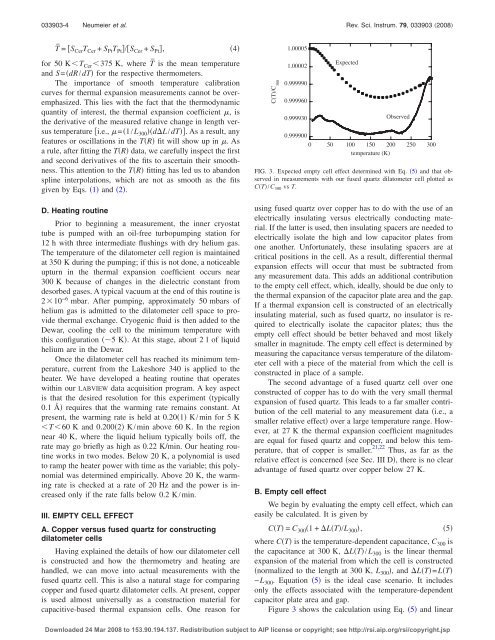
FIG. 3. Expected empty <strong>cell</strong> effect determined with Eq. 5 and that observed<br />
in measurements with our <strong>fused</strong> <strong>quartz</strong> <strong>dilatometer</strong> <strong>cell</strong> plotted as<br />
CT/C 300 vs T.<br />
using <strong>fused</strong> <strong>quartz</strong> over copper has to do with the use <strong>of</strong> an<br />
electrically insulating versus electrically conducting material.<br />
If the latter is used, then insulating spacers are needed to<br />
electrically isolate the high and low capacitor plates from<br />
one another. Un<strong>for</strong>tunately, these insulating spacers are at<br />
critical positions in the <strong>cell</strong>. As a result, differential thermal<br />
expansion effects will occur that must be subtracted from<br />
any measurement data. This adds an additional contribution<br />
to the empty <strong>cell</strong> effect, which, ideally, should be due only to<br />
the thermal expansion <strong>of</strong> the capacitor plate area and the gap.<br />
If a thermal expansion <strong>cell</strong> is <strong>constructed</strong> <strong>of</strong> an electrically<br />
insulating material, such as <strong>fused</strong> <strong>quartz</strong>, no insulator is required<br />
to electrically isolate the capacitor plates; thus the<br />
empty <strong>cell</strong> effect should be better behaved and most likely<br />
smaller in magnitude. The empty <strong>cell</strong> effect is determined by<br />
measuring the capacitance versus temperature <strong>of</strong> the <strong>dilatometer</strong><br />
<strong>cell</strong> with a piece <strong>of</strong> the material from which the <strong>cell</strong> is<br />
<strong>constructed</strong> in place <strong>of</strong> a sample.<br />
The second advantage <strong>of</strong> a <strong>fused</strong> <strong>quartz</strong> <strong>cell</strong> over one<br />
<strong>constructed</strong> <strong>of</strong> copper has to do with the very small thermal<br />
expansion <strong>of</strong> <strong>fused</strong> <strong>quartz</strong>. This leads to a far smaller contribution<br />
<strong>of</strong> the <strong>cell</strong> material to any measurement data i.e., a<br />
smaller relative effect over a large temperature range. However,<br />
at 27 K the thermal expansion coefficient magnitudes<br />
are equal <strong>for</strong> <strong>fused</strong> <strong>quartz</strong> and copper, and below this temperature,<br />
that <strong>of</strong> copper is smaller. 21,22 Thus, as far as the<br />
relative effect is concerned see Sec. III D, there is no clear<br />
advantage <strong>of</strong> <strong>fused</strong> <strong>quartz</strong> over copper below 27 K.<br />
B. Empty <strong>cell</strong> effect<br />
We begin by evaluating the empty <strong>cell</strong> effect, which can<br />
easily be calculated. It is given by<br />
CT = C 300 1+LT/L 300 ,<br />
5<br />
where CT is the temperature-dependent capacitance, C 300 is<br />
the capacitance at 300 K, LT/L 300 is the linear thermal<br />
expansion <strong>of</strong> the material from which the <strong>cell</strong> is <strong>constructed</strong><br />
normalized to the length at 300 K, L 300 , and LT=LT<br />
−L 300 . Equation 5 is the ideal case scenario. It includes<br />
only the effects associated with the temperature-dependent<br />
capacitor plate area and gap.<br />
Figure 3 shows the calculation using Eq. 5 and linear<br />
Downloaded 24 Mar 2008 to 153.90.194.137. Redistribution subject to AIP license or copyright; see http://rsi.aip.org/rsi/copyright.jsp