Power Antenna - Pontiac Custom Safari 55 56 & 57
Power Antenna - Pontiac Custom Safari 55 56 & 57
Power Antenna - Pontiac Custom Safari 55 56 & 57

You also want an ePaper? Increase the reach of your titles
YUMPU automatically turns print PDFs into web optimized ePapers that Google loves.
Reassembly, Lubrication and Adjustment:<br />
To reassemble the power antenna, simply assemble in reverse order of the above disassembly<br />
instructions.<br />
Assemble the antenna mast pieces after plating (use a high grade metal polish on the stainless steel<br />
mast rod), lightly oiling the sections to ensure the telescope smoothly without binding. Screw the<br />
replated mast tip back onto the stainless steel rod to secure the mast assembly.<br />
Slide the lower tube grommet over the reassembled mast assembly and reinstall the mast assembly &<br />
lower grommet into the upper antenna tube. Resolder the antenna lead pin to the mast. Push any<br />
excess lead wire back inside the tube and reinstall the lead pin and grommet in the antenna tube hole.<br />
Reinstall the lead pin bracket and antenna lead with a new cork gasket. Reinstall the upper antenna<br />
tube grommet.<br />
Reinstall the tube grommet in the drive mechanism upper case, aligning both the specialized brass<br />
washer and grommet to mate properly with the lower grommet in the antenna tube. Slide the nylon<br />
mast lead down through the tube grommet in the upper drive mechanism case and replace the 3 screws<br />
holding the antenna tube to the upper case cover.<br />
Slide the antenna nylon lead through the two steel drive wheels in the drive mechanism, ensuring the<br />
wide sides of the lead are in contact with and centered between the two drive wheels. Slip the upper<br />
case in place and reinstall the three case screws.<br />
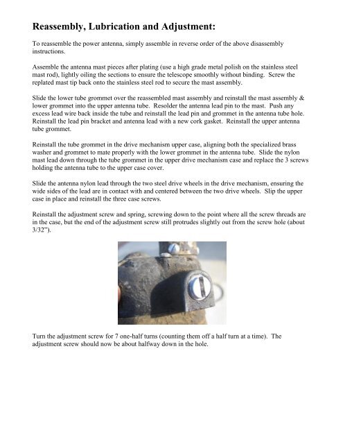
Reinstall the adjustment screw and spring, screwing down to the point where all the screw threads are<br />
in the case, but the end of the adjustment screw still protrudes slightly out from the screw hole (about<br />
3/32”).<br />
Turn the adjustment screw for 7 one-half turns (counting them off a half turn at a time). The<br />
adjustment screw should now be about halfway down in the hole.