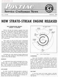
Contents / General Description / Carter WGD 2
Contents / General Description / Carter WGD 2
Contents / General Description / Carter WGD 2

You also want an ePaper? Increase the reach of your titles
YUMPU automatically turns print PDFs into web optimized ePapers that Google loves.
ENGINE FUEL<br />
6B-l<br />
ENGINE FUEL<br />
CONTENTS OF THIS SECTION<br />
SUBJECT<br />
HEAT CONTROL<br />
FUEL FILTER<br />
CARBURETOR AIR CLEANER AND<br />
PAGE<br />
6B-l<br />
6B-l<br />
SILENCER ..... .. . . . . . . . . . . . . . 6B-2<br />
CARTER <strong>WGD</strong> TWO BARREL CARBURETOR<br />
<strong>Description</strong><br />
Adjustments on Car ................ .<br />
6B-2<br />
6B-9<br />
Periodic Service ................... . 6B-9<br />
Overhaul and Adjust ........... . 6B-9<br />
Trouble Diagnosis and Testing<br />
6B-18<br />
Specifications .................. . 6B-19<br />
CARTER WCFB FOUR<br />
BARREL CARBURETOR<br />
<strong>Description</strong><br />
Adjustments on Car<br />
Overhaul and Adjust<br />
Trouble Diagnosis and Testing<br />
Specifications<br />
6B-21<br />
6B-25<br />
6B-25<br />
6B-36<br />
6B-36<br />
SUBJECT<br />
PAGE<br />
ROCHESTER 2GC TWO JET CARBURETOR<br />
<strong>Description</strong> .. 6B-39<br />
Adjustments on Car 6B-44<br />
Periodic Service 6B-45<br />
Overhaul and Adjust 6B-45<br />
Trouble Diagnosis and Testing 6B-53<br />
Specifications 6B-54<br />
ROCHESTER 4GC FOUR JET CARBURETOR<br />
<strong>Description</strong> 6B-56<br />
Adjustments on Car 6B-61<br />
Overhaul and Adjust 6B-62<br />
Trouble Diagnosis and Testing 6B-73<br />
Specifications 6B-73<br />
FUEL PUMP<br />
<strong>Description</strong><br />
Remove and Replace<br />
Overhaul<br />
Trouble Diagnosis and Testing<br />
6B-74<br />
6B-74<br />
6B-74<br />
6B-77<br />
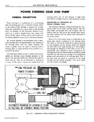
GENERAL DESCRIPTION<br />
HEAT CONTROL<br />
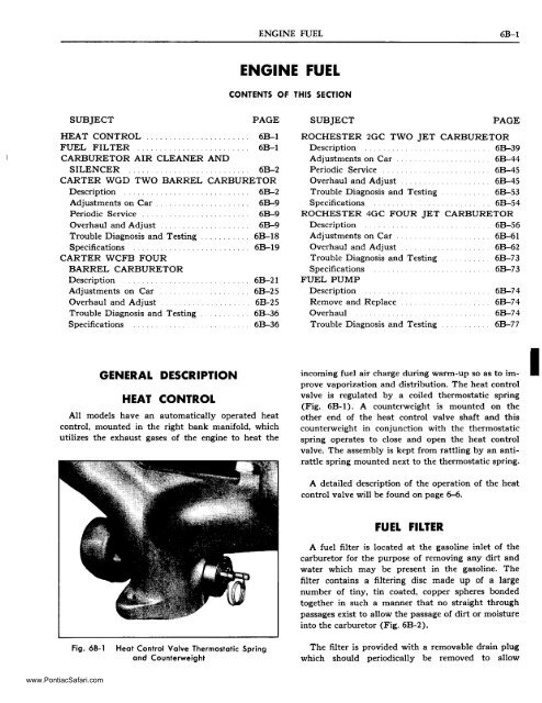
All models have an automatically operated heat<br />
control, mounted in the right bank manifold, which<br />
utilizes the exhaust gases of the engine to heat the<br />
incoming fuel air charge during warm-up so as to improve<br />
vaporization and distribution. The heat control<br />
valve is regulated by a coiled thermostatic spring<br />
(Fig. 6B-l). A counterweight is mounted on the<br />
other end of the heat control valve shaft and this<br />
counterweight in conjunction with the thermostatic<br />
spring operates to close and open the heat control<br />
valve. The assembly is kept from rattling by an antirattle<br />
spring mounted next to the thermostatic spring.<br />
A detailed description of the operation of the heat<br />
control valve will be found on page 6-6.<br />
I<br />
FUEL FILTER<br />
A fuel filter is located at the gasoline inlet of the<br />
carburetor for the purpose of removing any dirt and<br />
water which may be present in the gasoline. The<br />
filter contains a filtering disc made up of a large<br />
number of tiny, tin coated, copper spheres bonded<br />
together in such a manner that no straight through<br />
passages exist to allow the passage of dirt or moisture<br />
into the carburetor (Fig. 6B-2).<br />
Fig. 68-1<br />
Heat Control Valve Thermostatic Spring<br />
and Counterweight<br />
The filter is provided with a removable drain plug<br />
which should periodically be removed to allow<br />
www.PontiacSafari.com
6B-2 1955 PONTIAC SHOP MANUAL<br />
DESCRIPTION<br />
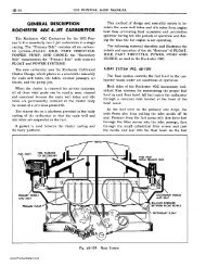
CARTER <strong>WGD</strong> DUAL CLIMATIC ®<br />
CONTROL* CARBURETOR<br />
NOTE: The following illustrations are used by<br />
permission of the copyright owner <strong>Carter</strong> Carburetor<br />
Corporation, St. Louis, Missouri. 6B-3<br />
through 6B-9, 6B-27, 6B-34, 6B-35, 6B-37.<br />
The <strong>Carter</strong> Model WGn dual carburetor combines<br />
design features of <strong>Carter</strong> carburetors used previously<br />
on Pontiac engines with several new features all in<br />
one easy-to-service assembly. A few of its new<br />
features are: Reduced over-all height, exhaust heated<br />
flange, simplified and accessible adjustments and a<br />
new compact Climatic Control choke.<br />
Five conventional circuits, as used in previous<br />
carburetors, are to be found in this unit. They are:<br />
Fig. 68-2<br />
Cross-Section of Fuel Filter<br />
collected dirt and water to drain. In cases where<br />
excessive foreign material has collected in the filter<br />
and fuel starvation occurs the filter should be removed<br />
for cleaning. Before removing filter remove<br />
the drain plug and drain filter, then remove and<br />
agitate the filter in carburetor solvent or its<br />
equivalent. Direct an air stream through the outlet<br />
port of the filter to force dirt from the filter element<br />
through the inlet port or drain port. Rinse the filter<br />
in kerosene and again direct an air stream through<br />
the outlet port. Install drain plug and reinstall filter.<br />
CARBURETOR AIR CLEANER<br />
AND SILENCER<br />
Combined air cleaners and silencers are used on<br />
all models. These units filter air entering the<br />
carburetor to keep abrasive dust from being carried<br />
into the engine, and silence the induction system noise<br />
emanating from the carburetor.<br />
The air cleaner has an oil reservoir in its base<br />
so air entering the carburetor first strikes the oil<br />
in the cleaner reservoir, this coupled with the rapid<br />
change in direction of the air flow causes the heavier<br />
dust particles to be picked up by the oil. The high<br />
velocity of the air stream picks up some of the oil<br />
and carries it upward into the filter element through<br />
which the air next passes thus keeping the element<br />
continually washed and moistened with oil.<br />
Float Circuit<br />
Low-Speed Circuit<br />
High-Speed Circuit<br />
Pump Circuit<br />
Climatic Control (Choke) Circuit<br />
These circuits are described and illustrated schematically<br />
in the following text.<br />
Figures 6B-lO, 6B-11, and 6B-12 illustrate the<br />
passages as they actually appear to the carburetor<br />
mechanic.<br />
FLOAT CIRCUIT (FIG. 68-3J<br />
The purpose of the float circuit is to maintain a<br />
supply of fuel at the proper level in the bowl for<br />
use by the low-speed, high-speed and pump circuits.<br />
Setting the float to specifications assures an<br />
adequate supply of fuel in the bowl for all operating<br />
conditions. Float adjustment must be made with the<br />
bowl cover gasket removed and the bowl cover held<br />
inverted and level at eye height with the free weight<br />
of the float resting on the intake needle. Adjust the<br />
float by bending the float arm. To avoid placing unnecessary<br />
strain on the float do not grasp the float<br />
shell when bending the float arm.<br />
*"Climatic Control" Reg. U.S. Pat. Off.<br />
www.PontiacSafari.com
ENGINE FUEL-CARTER TWO BARREL 6B-3<br />
ECONOMISS!<br />
_~_-o, STRAINER<br />
NEEDLE & SEAT<br />
METERING 'VU··e.!:---j<br />
JET<br />
LOW<br />
JET<br />
Fig. 6B-3<br />
Float Circuit-<strong>Carter</strong><br />
Fig. 6B-4<br />
low Speed Circuit-<strong>Carter</strong><br />
Inspect the intake needle and seat, and float assembly<br />
for wear. The carburetor bowl and the intake<br />
strainer screen should be clean and free of dirt, gum,<br />
or other foreign matter.<br />
The bowl is vented through the metering rod<br />
chamber in the air horn to outside atmosphere. The<br />
bowl vent is calibrated to provide proper air pressure<br />
above the fuel at all times. The bowl cover<br />
gasket seals the fuel bowl, idle and vacuum passages.<br />
To assure a positive seal, always use a new<br />
bowl cover gasket when re-assembling. An air leak<br />
at this point can result in a performance or economy<br />
complaint.<br />
LOW-SPEED CIRCUIT (FIG. 6S-4}<br />
Fuel for idle and early part throttle operation is<br />
metered through the low-speed circuit.<br />
Fuel enters the idle wells through the metering rod<br />
jets. The low-speed jets measure the amount of fuel<br />
for idle and early part throttle operation. The air<br />
by-pass passages, economizers and idle air bleeds are<br />
carefully calibrated and serve to break up the liquid<br />
fuel and mix it with air as it moves through the<br />
passages to the idle ports and idle adjustment screw<br />
ports. Turning the idle adjustment screws toward<br />
their seats reduces the quantity of fuel mixture<br />
supplied by the idle circuit.<br />
, The idle ports are slot shaped. As the throttle<br />
valves are opened more of the idle ports are uncovered<br />
allowing a greater quantity of the fuel and<br />
air mixture to enter the carburetor bores.<br />
Air leakage at the gasketed surface surrounding<br />
the low-speed mixture passages or between the flange<br />
and manifold may cause poor idle and low-speed<br />
operation. Always use new gaskets.<br />
All by-passes, bleeds, economizers, idle ports, idle<br />
adjustment screw ports, as well as the bores of the<br />
flange must be clean and free of carbon. Obstructions<br />
will cause poor low-speed engine operation. Worn or<br />
damaged idle adjustment screws or low-speed jets<br />
should be replaced.<br />
To combat engine stalling during warm-up on cool,<br />
humid days caused by "carburetor icing", exhaust gas<br />
is circulated through the passage in the base of the<br />
carburetor flange. The heat transferred is sufficient<br />
to eliminate ice formation at the throttle valve<br />
edges and idle ports.<br />
HIGH-SPEED CIRCUIT (FIG. 6S-5}<br />
Fuel for part throttle and full throttle operation is<br />
supplied through the high-speed circuit.<br />
The position of the metering roas in the metering<br />
rod jets controls the amount of fuel flowing in the<br />
high-speed circuit. The position of the metering rods<br />
is dual controlled, mechanically by movement of the<br />
throttle and by manifold vacuum applied to the<br />
vacuum piston on the vacumeter link.<br />
MECHANICAL METERING ROD ACTION<br />
During part throttle operation, manifold vacuum<br />
pulls the vacumeter piston, link and metering rod<br />
assembly down holding the vacumeter link against<br />
www.PontiacSafari.com
68-4 1955 PONTIAC SHOP MANUAL<br />
ANTI· PERCOLATOR PASSAGES<br />
METERING<br />
ARM<br />
METERING "IH---4-+1<br />
ROD<br />
Fig. 6B·5<br />
High Speed Circuit-<strong>Carter</strong><br />
the metering rod countershaft arm. Movement of the<br />
metering rods will then be controlled by the metering<br />
rod countershaft arm which is connected to the<br />
throttle shaft. This is true at all times that the<br />
vacuum under the piston is strong enough to over·<br />
come the tension of the vacumeter spring.<br />
VACUUM METERING ROD ACTION<br />
Under any operating condition (acceleration, hill<br />
climbing, etc.), when the tension of the vacumeter<br />
spring overcomes the pull of vacuum under the<br />
piston, the metering rods will move toward their<br />
wide-open throttle or power position.<br />
ANTI-PERCOLATOR<br />
To prevent the vapor bubbles in the nozzle passages<br />
and low-speed wells caused by heat from<br />
forcing fuel out of the nozzles, anti-percolator passages,<br />
and calibrated plugs and bushings are used.<br />
Their purpose is to vent the vapors and relieve the<br />
pressure before it is sufficient to push the fuel out<br />
of the nozzles and into the intake manifold. Antipercolator<br />
plugs, bushings, and main nozzles are<br />
permanently installed and must not be removed in<br />
service.<br />
PUMP CIRCUIT (FIG. 6B-6J<br />
The accelerating pump circuit provides a measured<br />
amount of fuel, which is necessary to insure smooth<br />
engine operation for acceleration at low speeds.<br />
When the throttle is closed, the pump plunger<br />
moves upward in its cylinder and fuel is drawn into<br />
pump cylinder through the intake check. (Fig. 6B-7).<br />
The discharge check is seated at this time to prevent<br />
air being drawn into the cylinder. When the throttle<br />
is opened the pump plunger moves downward<br />
forcing fuel out through the discharge passage, past<br />
the discharge check, and out of the pump jets. When<br />
the plunger moves downward the intake check is<br />
closed preventing fuel from being forced back into<br />
the bowl.<br />
At higher speeds pump discharge is no longer<br />
necessary to insure smooth acceleration. When the<br />
throttle valves are opened, a pre-determined amount,<br />
the pump plunger bottoms in the pump cylinder<br />
eliminating pump discharge due to pump plunger<br />
movement at high speeds.<br />
www.PontiacSafari.com
ENGINE FUEL-CARTER TWO BARREL 6B-5<br />
CHOKE OPERATING<br />
LEVER<br />
THERMOSTATIC<br />
COIL<br />
REVOLVING TYPE<br />
BAFFLE<br />
VACUUM PASSAGE TO<br />
MANIFOLD<br />
. 'I<br />
Fig. 6B-6<br />
Pump Circuit-<strong>Carter</strong><br />
Fig. 6B-8<br />
Choke Circuit {Vacuum Passage)-<strong>Carter</strong><br />
PUMP ANTI-PERCOLATOR<br />
When the pump plunger is stationary the intake<br />
check is not seated. This permits fuel vapor pressure<br />
caused by heat to be relieved through the intake<br />
passages located in the plunger shaft.<br />
CLIMATIC CONTROL CHOKE CIRCUIT (FIG 68-8<br />
AND FIG. 68-9)<br />
The climatic control circuit provides a correct<br />
mixture necessary for quick cold engine starting and<br />
warm-up.<br />
Fig. 6B-7<br />
Pump Circuit {Plunger Detail)-<strong>Carter</strong><br />
When the engine is cold, tension of the thermostatic<br />
coil holds the choke valve closed. When the engine<br />
is started, air velocity against the offset choke valve<br />
causes the valve to open slightly against the thermostatic<br />
coil tension. Intake manifold vacuum applied<br />
to the choke piston also tends to pull the choke<br />
valve open. The choke valve assumes a position where<br />
tension of the thermostatic coil is balanced by the<br />
pull of vaccum on the piston and force of air velocity<br />
on the offset valve.<br />
When the engine starts, slots located in the sides<br />
of the choke piston cylinder are uncovered allowing<br />
intake manifold vacuum to draw warm air heated<br />
by the exhaust manifold, through the climatic cont~ol<br />
housing. The flow of warm air in turn heats the<br />
thermostatic coil and causes it to lose some of its<br />
tension. The thermostatic coil loses its tension<br />
gradually until the choke valve reaches full-open<br />
position.<br />
A secondary baffle plate revolves with the choke<br />
valve. The revolving baffle prevents the warm air<br />
entering the housing from striking the thermostatic<br />
coil until the choke valve opens a predetermined<br />
www.PontiacSafari.com
6B-6<br />
1955 PONTIAC SHOP MANUAL<br />
amount. This serves to delay the initial opening of<br />
the caoke.<br />
If the engine is accelerated during the warm-up<br />
period, the corresponding drop in manifold vacuum<br />
allows the thermostatic coil to momentarily close the<br />
choke, providing a richer mixture.<br />
SLOTS IN CHOKE "iIjI"---'j.<br />
PISTON CYLINDER<br />
During the warm-up period it is necessary to<br />
provide a fast idle speed to prevent engine stalling.<br />
This is accomplished by a fast idle cam connected<br />
to the choke shaft. The fast idle link attached to the<br />
throttle lever contacts the fast idle cam and prevents<br />
the throttle valve from returning to a normal warm<br />
engine idle position while the climatic control is in<br />
operation.<br />
Fig. 68-9<br />
Choke Circuit (Fast Idle Cam I-<strong>Carter</strong><br />
If during the starting period the engine becomes<br />
flooded, the choke valve may be opened manually to<br />
clean out any excessive fuel in the intake manifold.<br />
This may be accomplished by depressing the accelerator<br />
pedal to the floor mat and engaging the<br />
starter. The unloader projection on the fast idle link<br />
will contact the unloader arm on the choke shaft<br />
and in turn partially open the choke valve.<br />
VACUMETER PASSAGE<br />
IDLE<br />
ADJUSTMENT<br />
PORTS<br />
•<br />
CHOKE VACUUM<br />
Fig. 68-10<br />
Passage Identification (Flangel-<strong>Carter</strong><br />
www.PontiacSafari.com
I<br />
I<br />
I<br />
I<br />
ENGINE FUEL-CARTER TWO BARREL 68-7<br />
I<br />
I<br />
I<br />
I<br />
I<br />
I<br />
I<br />
I<br />
I<br />
I<br />
I<br />
I<br />
I<br />
I<br />
I<br />
I<br />
SUCTION PASSAGE TO CHOKE<br />
I<br />
I<br />
I<br />
VACUMETER PASSAGE I<br />
I<br />
I<br />
I<br />
I<br />
I<br />
I<br />
I<br />
I<br />
I<br />
I<br />
I<br />
I<br />
I<br />
II<br />
VAC SPARK PASSAGE<br />
IDLE OR LO SPEED PASSAGE<br />
Fig. 68-11<br />
Passage Identification (Bowl-Flangel-<strong>Carter</strong><br />
www.PontiacSafari.com
f<br />
....<br />
\0<br />
VI<br />
VI<br />
VACUMETER CYLINDER<br />
~<br />
~<br />
- ><br />
~<br />
rI><br />
S<br />
"t:I<br />
~<br />
~<br />
,<br />
CHOKE PASSAGE<br />
IDLE WELLS<br />
MAIN BODY<br />
Fig. 6B-12<br />
Passage Identification (Bowl,Air Horn,Choke Housing)-<strong>Carter</strong><br />
www.PontiacSafari.com
ENGINE FUEL-CARTER TWO BARREL 6B-9<br />
screw to give 450-475 engine RPM on Synchro-Mesh<br />
cars and 390-410 RPM in neutral on Hydra-Matic<br />
equipped cars. When adjusting, check to make sure<br />
that engine is at normal operating temperature and<br />
choke is open.<br />
The two idle mixture adjusting screws should be<br />
turned in or out equally to give an even, smooth<br />
idle at the correct idle speed as set above. Missing is<br />
a sign of too lean a mixture while "rolling" or<br />
"loping" indicates too rich a mixture. Turning the<br />
adjusting screws in leans the idle mixture. Normally,<br />
the correct idle mixture is obtained with the idle<br />
mixture screws % to 1 % turns open.<br />
Fig. 68-13<br />
Fast Idle Adiustment-<strong>Carter</strong><br />
ADJUSTMENTS ON CAR<br />
CARTER MODEL WDG CARBURETOR<br />
All adjustments with the exception of the on car<br />
fast idle adjustment and the idle speed and mixture<br />
adjustment are included in "OVERHAUL AND AD<br />
JUSTMENTS" procedure and can be done on the<br />
Car. Following are the fast idle adjustment and the<br />
idle speed and mixture adjustment.<br />
FAST 'DL.E ADJUSTMENT<br />
1. Remove air cleaner and silencer.<br />
2. With choke valve open, back off idle speed screw<br />
until throttle valve is fully closed.<br />
3. Turn idle speed screw until it just contacts lip<br />
of outer throttle lever.<br />
4. With choke valve closed, manually open throttle<br />
to full open position to position fast idle cam.<br />
5. With choke valve closed gauge J -5908 should<br />
just fit between end of adjusting screw and lip on<br />
outer throttle lever as shown in Fig. 6B-13. If gauge<br />
does not fit or excess clearance exists bend choke<br />
connecting rod to correct.<br />
'DL.E SPEED AND MIXTURE ADJUSTMENT<br />
Idle speed should be set by turning the idle speed<br />
CHOKE CLIMATIC CONTROL. ADJUSTMENT<br />
Direction for adjustment (lean or rich) is clearly<br />
marked on the thermostatic spring housing. The<br />
standard setting is one notch rich on Hydra-Matic<br />
equipped cars, one notch lean on Synchro=I\1esh. It<br />
should never be necessary to move the choke index<br />
more than two notches from the standard setting to<br />
take care of unusual conditions. If a need for greater<br />
adjustment appears to be necessary, trouble lies elsewhere<br />
than in the choke thermostatic spring adjustment.<br />
CARTER CARBURETOR<br />
PERIODIC SERVICE<br />
Lubricate accelerator pump arm countershaft every<br />
spring or fall or 10,000 miles as covered on page 0-4.<br />
OVERHAUL AND ADJUSTMENTS<br />
CARTER MODEL <strong>WGD</strong> CARBURETOR<br />
Flooding, stumble on acceleration and other performat'l.ce<br />
complaints are, in many instances, caused<br />
by the presence of dirt, water or other foreign matter<br />
in the carburetor. To aid in diagnosing the cause of<br />
the complaint, the carburetor should be carefully<br />
removed from the engine without draining the fuel<br />
from the bowl. The contents of the fuel bowl may<br />
then be examined for contamination as the carburetor<br />
is disassembled.<br />
The following is a step-by-step sequence by which<br />
the <strong>Carter</strong> Model <strong>WGD</strong> Carburetor may be completely<br />
disassembled and reassembled. Adjustments<br />
may be made and various parts of the carburetor may<br />
be serviced without completely disassembling the<br />
entire unit.<br />
www.PontiacSafari.com
6B-10 1955 PONTIAC SHOP MANUAL<br />
ROD<br />
L---__ -----II<br />
Fig. 68-14<br />
DISASSEMBL Y<br />
Carburetor Assembly-<strong>Carter</strong><br />
DISASSEMBLY OF AIR HORN<br />
1. Remove dust cover and remove strainer nut<br />
assembly (Fig. 6B-14).<br />
2. Remove throttle connector rod (Fig. 6B-14)<br />
and choke connector rod (Fig. 6B-1S) at both ends.<br />
3. Using a small screwdriver, pry end of throttle<br />
return spring off boss on air hom casting to release<br />
spring tension (Fig. 6B-16).<br />
4. Loosen set screws on metering rod arm, and<br />
pump arm, then slide countershaft out of casting<br />
(Fig. 6B-16).<br />
S. Remove metering rod arm.<br />
6. Remove metering rods from vacumeter piston<br />
link.<br />
7. Remove 8 bowl cover and air hom attaching<br />
screws and remove air hom assembly with all remaining<br />
parts attached (Fig. 6B-17).<br />
8. Remove float and needle and seat assembly<br />
from bowl cover.<br />
9. Disconnect vacumeter piston from link and remove<br />
link and metering rod spring assembly.<br />
10. Remove air hom gasket and both low speed jets.<br />
1...-.--1 __--------l<br />
Fig. 68-15<br />
Carburetor Assembly-<strong>Carter</strong><br />
11. Remove pump arm and link assembly from<br />
hole in pump plunger stem and remove plunger and<br />
spring.<br />
12. Remove thermostatic coil housing screws and<br />
retainers, housing, gasket, metal baffle plate, and fast<br />
idle link. NOTE: Under normal service the air hom<br />
may be cleaned without further disassembly. If complete<br />
disassembly is necessary, perform the remaining<br />
operations.<br />
PUMP ARM SET SCREW<br />
fig. 68-16<br />
METERING ROD ARM SET SCREW<br />
Removing Countershaft-<strong>Carter</strong><br />
www.PontiacSafari.com
ENGINE FUEL-CARTER TWO BARREL<br />
6B-ll<br />
FAST IDLE<br />
CAM SPRING<br />
Fig. 68-19<br />
Choke Piston, Shaft and Fast Idle Cam<br />
Assembly-<strong>Carter</strong><br />
16. Remove 3 self-tapping screws and remove<br />
piston housing and small piston housing gasket from<br />
air horn casting (Fig. 6B-20).<br />
Fig. 68-17<br />
Removing Air Horn Assembly-<strong>Carter</strong><br />
13. File off staked ends of choke valve screws and<br />
remove screws and valve.<br />
14. Rotate choke shaft while guiding piston until<br />
piston is clear of vacuum cylinder, and remove piston<br />
and shaft assembly. NOTE: It may be necessary to<br />
rotate fast idle cam to clear piston (Fig. 6B-18).<br />
15. Separate fast idle cam and spring assembly<br />
from choke lever by unhooking fast idle cam spring<br />
(Fig. 6B-19).<br />
DISASSEMBLY OF CARBURETOR BODY<br />
Check the fuel in the bowl for contamination by<br />
dirt, water, gum, or other foreign matter.<br />
1. Remove metering rod jets (Fig. 6B-21).<br />
2. Remove pump jet cluster and gasket (Fig.<br />
6B-21).<br />
3. Invert casting to remove vacumeter spring,<br />
pump discharge needle (Fig. 6B-21) and drain fuel.<br />
CAUTION: Never attempt to remove nozzles or<br />
anti-percolator plugs from body casting.<br />
PISTON HOUSING GASKET<br />
Fig. 68-18<br />
Removing Choke Piston and Shaft<br />
Assembly-<strong>Carter</strong><br />
Fig. 68-20<br />
Choke Piston Housing Gasket-<strong>Carter</strong><br />
www.PontiacSafari.com
6B-12 1955 PONTIAC SHOP MANUAL<br />
PUMP JET CLUSTER<br />
BODY TO FLANGE ATTACHING SCREWS<br />
VACUMETER SPRING<br />
METERING ROD JETS<br />
EXHAUST GAS PASSAGE<br />
THROTTLE SHAFT ARM<br />
BODY TO FLANGE SCREWS<br />
SCREW<br />
Fig. 6B-21<br />
Carburetor Bowl Assembly-<strong>Carter</strong><br />
Fig. 6B-22<br />
Throttle Flange Assembly-<strong>Carter</strong><br />
DISASSEMBLY OF THROTTLE FLANGE<br />
1. Remove four throttle flange attaching screws<br />
to separate the carburetor body from flange, and remove<br />
gasket (fig. 6B-22).<br />
2. Remove idle mixture adjusting screws and<br />
springs.<br />
NOTE: Under normal service the carburetor flange<br />
may be cleaned without further disassembly. If complete<br />
disassembly is necessary, perform the remaining<br />
operations.<br />
3. Remove throttle shaft arm attaching screw,<br />
washer and throttle shaft arm (Fig. 6B-22).<br />
4. File off staked ends of throttle valve attaching<br />
screws and remove screws and throttle valves.<br />
5. Remove shaft from throttle flange.<br />
CLEANING AND INSPECTION OF PARTS<br />
Dirt, gum, water or carbon contamination in or on<br />
the exterior moving parts of a carburetor are often<br />
responsible for unsatisfactory performance. For this<br />
reason, efficient carburetion depends upon careful<br />
cleaning and inspection while servicing.<br />
1. Thoroughly clean carburetor castings and all<br />
metal parts in clean cleaning solvent. CAUTION:<br />
Composition and plastic parts such as thermostatic<br />
coil housing and pump plunger should not be immersed<br />
in solvent. DO NOT SOAK AIR HORN<br />
ASSEMBLY IN CLEANER OR SOLVENT FOR<br />
MORE THAN ONE HALF HOUR IF CHOKE<br />
PISTON HOUSING HAS NOT BEEN REMOVED.<br />
2. Blowout all passages in castings with compressed<br />
air and blow off all parts so they are free<br />
of solvent. CAUTION: Do not use drills or wire to<br />
clean out jets or parts as this may enlarge the<br />
opening and affect carburetor operation.<br />
3. Carefully inspect parts for wear and replace<br />
those which are worn. Check the following specific<br />
points:<br />
a. Carefully note the condition of slots in the<br />
choke piston cylinder. If they are found to be<br />
carbonized, remove Welch plug in the bottom of the<br />
climatic control housing by piercing center with a<br />
small pointed instrument and prying outward. Care<br />
should be exercised so that damage will not result<br />
to the casting when removing this plug. Before installing<br />
new plug, carbon present in piston cylinder<br />
slots should be removed and the Welch plug seat<br />
should be carefully cleaned.<br />
b. Remove carbon from bores of flange with sandpaper;<br />
never use emery cloth.<br />
c. Remove carbon from hot air passage in base<br />
of flange (Fig. 6B-22) and from mating holes in<br />
intake manifold.<br />
d. See if needle or seat is worn; if so, both must<br />
be replaced.<br />
www.PontiacSafari.com
ENGINE FUEL-CARTER TWO BARREL 68-13<br />
e. Check float pin for excessive wear.<br />
f. Check float for dents and excessive wear on lip.<br />
Check for fluid inside float by shaking. Replace float<br />
if any of above are present.<br />
g. Check bowl cover for wear in countershaft hole<br />
(hole worn egg shaped).<br />
h. Check throttle shaft for excessive wear (looseness<br />
or rattle in body flange casting).<br />
i. Check idle mixture adjusting screws for burrs.<br />
Replace if burred.<br />
j. Inspect metering rods and jets for bent rods<br />
and signs of wear, and replace if bent rods or wear are<br />
noted. Always replace both metering rod and jet;<br />
do not install new rod in old jet or vice versa.<br />
k. Inspect pump plunger assembly. If leather is not<br />
in good condition, replace plunger. Check operation<br />
of pump intake valve in pump plunger.<br />
4. Check part numbers of jets, metering rod, etc.<br />
(where stamped with <strong>Carter</strong> part number), against<br />
Master Parts Catalog to make sure correct .parts<br />
will be installed.<br />
ASSEM8l Y AND ADJUSTMENT<br />
ASSEMBLY OF THROTTLE FLANGE<br />
Fig. 68-24<br />
Throttle Shaft Installed-<strong>Carter</strong><br />
1. Install throttle shaft and lever assembly in<br />
flange.<br />
2. Install throttle valves with trademark (c in<br />
circle) toward idle ports when viewing flange from<br />
manifold side (Fig. 6B-23).<br />
3. Hold valve firmly in place with fingers and tap<br />
lightly with screwdriver to center valves before<br />
tightening screws. Always use new screws.<br />
4. Install throttle shaft arm, washer and attaching<br />
screw in position shown in Fig. 6B-24. Throttle valves<br />
should be fully closed while tightening screw.<br />
5. Install idle mixture adjustment screws and<br />
spring. CAUTION: To avoid possible damage to<br />
idle mixture screws, do not tighten more than finger<br />
tight. Temporary idle adjustment should be made<br />
by turning idle mixture screws until they are finger<br />
tight and then backing out 1-1 Yz turns.<br />
6. Assemble body casting to flange using new<br />
gasket. Tighten screws evenly and securely (Fig.<br />
6B-22). CAUTION: If two lower screws are not<br />
tightened securely poor engine idle will result.<br />
Fig. 68-23<br />
Correct Installation of Throttle Valves-<strong>Carter</strong><br />
ASSEMBLY OF CARBURETOR BODY<br />
1. Install pump discharge needle (point downward),<br />
(Fig. 6B-2S) pump jet cluster gasket and<br />
pump jet cluster and screw. Always use new gasket.<br />
2. Blowout passages in body with compressed air.<br />
3. Install vacuum piston spring into vacumeter<br />
cylinder.<br />
4. Install metering rod jets. (No gaskets are used.)<br />
NOTE: No pump intake strainer screen is used.<br />
www.PontiacSafari.com
6B-14 1955 PONTIAC SHOP MANUAL<br />
PUMP DISCHARGE NEEDLE<br />
TO ADJUST J-4465<br />
FLOAT<br />
LEVEL<br />
G<br />
Fig. 6B-27<br />
Float Adjustment-<strong>Carter</strong><br />
Fig. 68-25<br />
Installing Pump Discharge Needle-<strong>Carter</strong><br />
ASSEMBLY OF AIR HORN<br />
1. Assemble pump plunger spring over plUnger<br />
shaft.<br />
2. Insert pump shaft through air horn and retain<br />
in position with link and pump arm assembly (Fig.<br />
6B-26).<br />
6. FLOAT ADJUSTMENT: With air horn inverted<br />
and needle seated adjust float arm so clearance<br />
between top center of float and air horn is 7/32"-+<br />
1/64". Use gauge J-4465 (Fig. 6B-27). To avoid<br />
placing any strain on the float, do not grasp the float<br />
shell while bending the float arm.<br />
7. Position gasket on air horn.<br />
3. Install needle seat and gasket assembly.<br />
4. Install low speed jets. (No gaskets used.)<br />
5. Attach needle pull clip and needle to float, then<br />
install float assembly and float pin.<br />
Fig. 68-26<br />
Installing Pump Shaft-<strong>Carter</strong><br />
Fig. 6B-28<br />
Installing Vacumeter Piston Link-<strong>Carter</strong><br />
www.PontiacSafari.com
ENGINE FUEL-CARTER TWO BARREL 6B-15<br />
I<br />
is DIA.WIRE<br />
Fig. 68-29<br />
Wire Hook For Installing Throttle<br />
Return Spring-<strong>Carter</strong><br />
8. Install vacumeter piston link and metering rod<br />
spring assembly in slot with protruding lip toward<br />
air horn (Fig. 6B-28).<br />
9. Install vacumeter piston on link with pin extending<br />
away from float.<br />
10. Carefully position the air horn assembly on<br />
the carburetor body being sure the vacumeter piston<br />
and pump plunger are aligned so they enter their<br />
respective bores.<br />
11. Install air horn screws, starting with center<br />
screws tighten evenly and securely.<br />
12. Place throttle return spring on countershaft.<br />
13. Hold pump arm in place and press countershaft<br />
through arm.<br />
14. Hold metering rod arm with finger extending<br />
through slot in vacumeter piston link and press<br />
shaft in place making sure shaft is completely through<br />
metering rod arm. Tighten pump arm locking screw.<br />
Fig. 68-31<br />
Choke Piston Housing Gasket<br />
Installed-Corter<br />
15. Using a wire hook as shown in Fig. 6B-29, wind<br />
throttle return spring % tum and catch on boss as<br />
shown in Fig. 6B-30.<br />
16. Install throttle connector rod and clevis clips.<br />
17. Install metering rods as follows: Catch rnetering<br />
rod spring loop with lower end of rod as rod is inserted,<br />
then twist "eye" of rod onto vacumeter piston<br />
link assembly.<br />
18. Install new choke piston housing gasket in air<br />
horn (Fig. 6B-31).<br />
19. Assemble piston housing assembly to air horn.<br />
Carefully tighten screws alternately as they are of<br />
the self-tapping type and must be pulled down<br />
securely.<br />
20. Connect the fast idle cam spring to the choke<br />
shaft lever (Fig. 6B-32). Install choke piston, lever,<br />
link and shaft in the air hom.<br />
Fig. 68-30<br />
Installing Counters haft Spring-<strong>Carter</strong><br />
Fig. 68-32<br />
Choke Piston, Shaft and Fast Idle Com<br />
Assembly-Corter<br />
www.PontiacSafari.com
6B-16 1955 PONTIAC SHOP MANUAL<br />
TOP OF PUMP ARM<br />
Fig. 68-34<br />
Accelerator Pump Adjustment-<strong>Carter</strong><br />
Fig. 68-33<br />
Fast Idle Link Installed-<strong>Carter</strong><br />
21. Install choke valve so that trademark (c in<br />
circle) is visible from the top of the carburetor with<br />
the valve in the closed position.<br />
22. Center choke valve and install new screws.<br />
IMPORTANT: Make sure that neither valve nor<br />
shaft binds in any position and that valve drops free<br />
by its own weight.<br />
23. Install fast idle link while holding throttle and<br />
choke valves wide open (Fig. 6B-33).<br />
24. Install choke connector rod and retainers.<br />
25. Install intake strainer screen, nut and gasket.<br />
ADJUSTMENTS<br />
NOTE: Adjustments should be made in the following<br />
order. Assembly of air horn can then be completed<br />
as outlined on page 6B-18.<br />
1. Pump adjustment<br />
2. Metering rod adjustment<br />
3. Fast idle adjustment<br />
4. Unloader adjustment<br />
PUMP ADJUSTMENT<br />
1. Back out idle speed screw until throttle valves<br />
seat in bores of carburetor.<br />
2. Hold straight edge across top of dust cover boss<br />
at pump arm (Fig. 6B-34). Bend rod at upper angle<br />
until upper flat of pump arm is parallel with straight<br />
edge while throttle valves are seated. (Use Tool<br />
J-5496.)<br />
METERING ROD ADJUSTMENT<br />
1. Back out idle speed screw until throttle valves<br />
seat.<br />
2. Press down on vacumeter piston link until metering<br />
rods bottom in carburetor body (Fig. 6B-35).<br />
3. Holding rods in this downward position and with<br />
throttle valve seated, revolve metering rod arm until<br />
finger on arm contacts lip of vacumeter link. Hold<br />
in place and carefully tighten clamp screw.<br />
4. Install dust cover.<br />
FAST IDLE ADJUSTMENT (CARBURETOR<br />
REMOVED)<br />
1. Hold choke valve tightly closed.<br />
2. Open and close throttle valves. (This positions<br />
fast idle link on high step of fast idle cam.)<br />
www.PontiacSafari.com
ENGINE FUEL-CARTER TWO BARREL 6B-17<br />
5/32 GAUGE J-2573-6<br />
Fig. 6B-37<br />
Un loader Adjustment-<strong>Carter</strong><br />
Fig. 6B-35<br />
Metering Rod Adjustment-<strong>Carter</strong><br />
3. While holding throttle valves closed with slight<br />
tension there should be .026# (gauge J -5908) clearance<br />
between the center of throttle valves and bore,<br />
opposite idle mixture adjusting screws (Fig. 6B-36).<br />
4. To adjust, bend lower angle of choke connector<br />
rod. Use tool J-5496.<br />
UNLOADER ADJUSTMENT<br />
1. Hold throttle valves wide open.<br />
2. Close choke valve as far as possible without<br />
forcing.<br />
3. Clearance should be %/' -t-Vt;4" (gauge J-2573-6)<br />
between top edge of choke valve and inner wall of<br />
air horn.<br />
4. Adjust by bending choke shaft unloader arm<br />
(Fig. 6B-37). Use tool J-5496.<br />
Fig. 6B-36<br />
Fast Idle Adjustment (Carburetor Removed)<br />
<strong>Carter</strong><br />
Fig. 68-38<br />
Choke Baffle Plate Installed-<strong>Carter</strong><br />
www.PontiacSafari.com
68-18 1955 PONTIAC SHOP MANUAL<br />
TO COMPLETE ASSEMBLY OF AIR HORN<br />
1. Install choke baffle plate and gasket as shown in<br />
Fig.6B-38.<br />
2. Install thermostatic coil and housing assembly<br />
to air hom with index mark on plastic housing positioned<br />
at the bottom. Revolve housing in direction<br />
opposite to arrow until index mark on thermostatic<br />
coil housing assembly is one notch past center index<br />
mark on piston housing. Tighten attaching screws<br />
securely.<br />
TEST BEFORE INSTALLATION ON ENGINE<br />
It is good shop practice to fill the carburetor bowl<br />
before installing the carburetor. This reduces the<br />
strain on the starting motor and battery and reduces<br />
the possibility of backfiring while attempting to start<br />
the engine. A fuel pump clamped on the bench, a<br />
l!,mall supply of fuel and the necessary fittings enable<br />
the carburetor to be plIed and the operation of the<br />
float and intake needle and seat to be checked. Operate<br />
the throttle several times and check the discharge<br />
from the pump jets before installing the<br />
carburetor.<br />
TROUBLE DIAGNOSIS AND<br />
TESTING-CARTER<br />
When carburetor troubles are encountered they<br />
can usually be corrected by making the adjustments<br />
outlined under "Adjustments on Car". The following<br />
list of common troubles and their causes will frequently<br />
save considerable time in locating the cause<br />
of the difficulty. NOTE: Before any work is performed<br />
on the carburetor, make sure trouble is not<br />
due to poor compression, or in the ignition system<br />
due to improper timing, defective spark plugs, burned<br />
ignition points, etc. Always diagnose performance<br />
trouble by using the Pontiac Tune-N-Test Guide<br />
before adjusting or repairing the carburetor.<br />
When the cause of trouble is not located by the<br />
Tune-N-Test, check for trouble in the carburetion<br />
system as follows:<br />
POOR FUEL ECONOM Y<br />
NOTE: Before any attempt is made to improve<br />
fuel economy the actual gasoline mileage should<br />
be determined using a tenth of a gallon tester.<br />
If the mileage obtained during this test compares<br />
favorably with that found on other normal<br />
cars, the poor mileage must be attributed to the<br />
driving conditions or driving habits of the owner.<br />
Also consider factors such as dragging brakes,<br />
soft tires, improper tire size, and improper speedometer<br />
driven gear.<br />
1. Check automatic choke to see that it operates<br />
properly and that it is correctly indexed.<br />
2. Inspect manifold heat valve to see that it operates<br />
freely.<br />
3. Check for leaks in fuel line fittings, at fuel tank,<br />
or at fuel pump bowl.<br />
4. Check for dirty or restricted air cleaner.<br />
5. Test for high fuel pump pressure.<br />
6. Check metering rod adjustment.<br />
7. Disassemble carburetor and inspect throttle<br />
body to bowl gasket and air hom gasket for evidence<br />
of leaks in vacuum passages to metering rod vacuum<br />
piston and automatic choke vacuum piston. Check<br />
float level.<br />
8. Check for worn metering rods and jets.<br />
SURGING CONDITION AFTER SHORT STOP<br />
WITH HOT ENGINE<br />
1. ,Lean carburetor adjustment. Check float level<br />
and metering rod adjustment. Also make sure correct<br />
metering rods are installed.<br />
2. Weak fuel pump. Check fuel pump pressure and<br />
output as outlined on page 6B-77.<br />
FLAT SPOT OR POOR ACCELERATION<br />
1. See that manifold heat valve operates freely and<br />
that thermostat is properly installed.<br />
2. Check accelerator pump action. Remove air<br />
hom and open throttle to observe stream from nozzles.<br />
If pump is not functioning properly check pump<br />
adjustment.<br />
3. Check pump for defective plunger leather, obstructed<br />
passages, or leaking intake check valve.<br />
ROUGH IDLE WHICH CANNOT BE CORRECTED<br />
BY MIXTURE AND SPEED ADJUSTMENT<br />
1. Check manifold gaskets for evidence of air leak<br />
into intake manifold. When kerosene is used ensure<br />
that no liquid or fumes enter choke stove by disconnecting<br />
heat tubes.<br />
2. Check float level.<br />
3. Check idle jets for obstructions.<br />
www.PontiacSafari.com
ENGINE FUEL-CARTER TWO BARREL 6B-19<br />
4. Check idle passages in carburetor castings for<br />
obstructions.<br />
S. Check for leak between exhaust gas passage and<br />
throttle bore.<br />
IMPROPER HIGH SPEED PERFORMANCE<br />
1. Check spark plug gap.<br />
2. Check distributor points.<br />
3. Test fuel pump output and pressure as outlined<br />
on page 6B-77.<br />
4. Check throttle body to bowl gasket and air horn<br />
gasket for evidence of air leaks into vacuum passage<br />
to metering rod vacuum piston.<br />
S. Check metering rod and float level adjustments.<br />
6. Check for worn or incorrect Il\l'tering rods or<br />
jets.<br />
7. Check for restriction in bowl vent.<br />
8. Inspect high speed passages and nozzles for obstructions.<br />
FLOODING OR LEAKING<br />
1. Test fuel pump for excessive pressure.<br />
2. Clean intake strainer and check for dirt on intake<br />
needle or seat.<br />
3. Check float adjustment (make sure float is centered<br />
so it does not rub side of bowl).<br />
4. Check for leaking or collapsed float.<br />
S. Check for worn intake needle and seat.<br />
6. Inspect bowl casting for cracks or loose passage<br />
plugs.<br />
STALLING DURING WARM-UP DUE TO ICING<br />
Check exhaust gas passage for carbon build up.<br />
Clean hole to manifold and manifold flange:;surface.<br />
Always use new manifold to carburetor gaskets to<br />
ensure against leak.<br />
SPECIFICATIONS<br />
CARTER MODEL <strong>WGD</strong> CARBURETOR<br />
Flange Size<br />
Main Venturi (I.D.)<br />
Primary Venturi (I.D.)<br />
Secondary Venturi (I.D.)<br />
Throttle Bore .................. .<br />
Low Speed Jet Tube<br />
Jet 2182S-SA<br />
2207S<br />
By-Pass ....<br />
Economizer<br />
Idle Bleed<br />
Idle Port (upper)<br />
Distance above throttle valve<br />
when valve is tightly closed<br />
Idle Port (lower, for idle screw)<br />
lY
68-20<br />
1955 PONTIAC SHOP MANUAL<br />
Main Nozzle<br />
Metering Rod (vacumeter type)<br />
<strong>Carter</strong> No .......................... .<br />
Economy Step ............. .<br />
Middle Step Tapers to ............. .<br />
Power Step ......................... .<br />
Permanently Installed<br />
Hydra-Matic Synchro-Mesh<br />
2182S 2182SA-SB 2207S-SB<br />
75-1124<br />
.063"<br />
.056"<br />
.048"<br />
75-1136<br />
.063"<br />
.056"<br />
.048"<br />
75-1135<br />
.060"<br />
.055"<br />
.048"<br />
Metering Rod Settings .................... No Gauges-Necessary to Follow<br />
Adjustment Instructions<br />
Metering Rod Jet ................................. . No. 44 Drill (.086")<br />
Gasoline Intake Needle Seat. . . . . . . . . . . . . . . . . . . . . . . .. No. 42 Drill (.0935")<br />
Vacuum Spark Port<br />
Diameter ....................................... .062"-.064"<br />
Distance from throttle valve<br />
with valve tightly closed ..................... .029"-.039" .040"-.050"<br />
(To Top of Port)<br />
-J-4465<br />
J-5908<br />
CARTER 2-BARREL SPECIAL TOOLS<br />
J-2573-6 . . .. , ........ .. Float level Gauge<br />
J-4465 . . . . . . . . Choke Unloader Gauge<br />
J-5496 . . . . . . . . . . . . . . ... Bending Tool<br />
J-5908 . . . . . . . . . . . . Fast Idle Gauge<br />
J-5923 ..................... Holding Stand<br />
J-5923<br />
J-5496<br />
J-2573-6<br />
SERVICE CRAFTSMAN NEWS REFERENCE<br />
News<br />
Year<br />
News<br />
No.<br />
Page<br />
No.<br />
Subject<br />
www.PontiacSafari.com