
You also want an ePaper? Increase the reach of your titles
YUMPU automatically turns print PDFs into web optimized ePapers that Google loves.
9-10 1955 PONTIAC SHOP MANUAL<br />
<strong>POWER</strong> <strong>STEERING</strong> <strong>GEAR</strong> <strong>AND</strong> <strong>PUMP</strong><br />
GENERAL DESCRIPTION<br />
Power steering is a combination of a recirculating<br />
ball nut steering gear and a hydraulic booster linked<br />
to the pitman shaft through a separate set of gear<br />
teeth and controlled by a spool valve on the steering<br />
shaft. Oil pressure for the hydraulic booster is provided<br />
by a positive displacement type pump, belt<br />
driven off the engine. A flow control valve located in<br />
the pump regulates pump output and pump pressure.<br />
All normal steering is accomplished with a maximum<br />
steering effort of approximately nine pounds on<br />
the steering wheel with the engine running. The<br />
booster cylinder dOes not assist in steering until a<br />
steering effort of approximately three pounds is required<br />
of the driver.<br />
The hydraulic system is only a booster and accomplishes<br />
no steering except through guidance of the<br />
driver. The unit does NOT steer beyond the path the<br />
driver has set. This can be illustrated in driving on<br />
a curve. If the driver removes his hands from the<br />
IilI& LOW PRESSU RE 01 L<br />
<strong>POWER</strong> CYLINDER<br />
steering wheel, the car will attempt to right itself<br />
and follow a straight course as with standard steering.<br />
DESCRIPTION Of OPERATION Of<br />
<strong>POWER</strong> <strong>STEERING</strong> <strong>GEAR</strong><br />
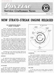
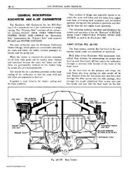
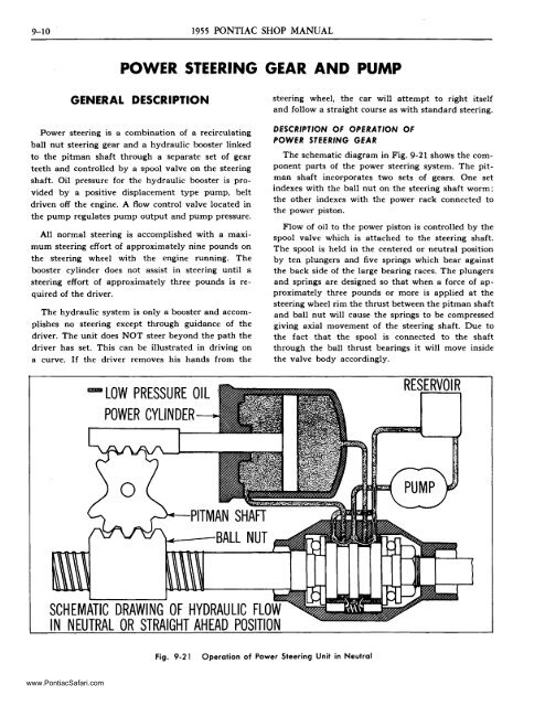
The schematic diagram in Fig. 9-21 shows the component<br />
parts of the power steering system. The pitman<br />
shaft incorporates two sets of gears. One set<br />
indexes with the ball nut on the steering shaft worm;<br />
the other indexes with the power rack connected to<br />
the power piston.<br />
Flow of oil to the power piston is controlled by the<br />
spool valve which is attached to the steering shaft.<br />
The spool is held in the centered or neutral position<br />
by ten plUngers and five springs which bear against<br />
the back side of the large bearing races. The plungers<br />
and springs are designed so that when a force of approximately<br />
three pounds or more is applied at the<br />
steering wheel rim the thrust between the pitman shaft<br />
and ball nut will cause the springs to be compressed<br />
giving axial movement of the steering shaft. Due to<br />
the fact that the spool is connected to the shaft<br />
through the ball thrust bearings it will move inside<br />
the valve body accordingly.<br />
RESERVOIR<br />
~-BALL NUT<br />
SCHEMATIC DRAWING OF HYDRAULIC FLOW<br />
IN NEUTRAL OR STRAIGHT AHEAD POSITION<br />
Fig. 9-21<br />
Operation of Power Steering Unit in Neutral<br />
www.PontiacSafari.com
<strong>POWER</strong> <strong>STEERING</strong> 9-11<br />
OIL FLOW IN NEUTRAL<br />
When the steering wheel is not being turned or is<br />
turned with a force of less than three pounds, the<br />
spool valve will remain centered as shown in Fig. 9-2l.<br />
Pump output will then be directed from the pressure<br />
inlet of the valve body past the spool valve to the return<br />
line to the reservoir. This pump output will<br />
simply be recirculated in the system without doing<br />
any work.<br />
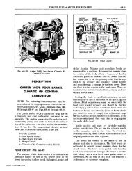
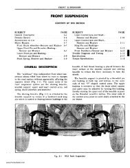
OIL FLOW DURING TURNS<br />
When the steering wheel is turned, a thrust will be<br />
developed between the pitman shaft and the ball nut.<br />
This thrust will increase as the steering effort at the<br />
steering wheel increases. When the effort at the wheel<br />
reaches three pounds, the force on the ball nut will<br />
move the steering shaft, compressing the plunger<br />
springs and moving the spool valve with it.<br />
When the spool valve moves as shown in Fig. 9-22<br />
on a left turn, oil is directed past the spool valve to<br />
the left side of the power piston. This pushes the<br />
piston to the right, assisting the driver in turning the<br />
wheel. Oil from the other side of the piston is directed<br />
back through the valve body to the pump reservoir.<br />
In addition oil pressure is directed against the spool<br />
centering plungers to supplement spring force in trying<br />
to center the spool. This causes the force required<br />
to turn the wheel to increase as the front wheels get<br />
harder to turn, giving the driver a natural feel of<br />
steering.<br />
When making a right turn the steering shaft and<br />
spool move in the opposite direction. This directs<br />
pressure to the opposite side of the piston. Oil flow<br />
is similar to that when making a left turn except it is<br />
in the opposite direction.<br />
A check valve in the control valve body allows the<br />
flow of oil from one side of the piston to the other,<br />
permitting normal manual steering of the car in case<br />
of pump failure.<br />
DESCRIPTION OF OPERATION OF<br />
<strong>POWER</strong> s.TEERING <strong>PUMP</strong><br />
The vane type pump is a positive displacement<br />
pump. Oil from the reservoir enters the pump body<br />
and is picked up by rotor vanes through two inlet<br />
ports and pockets and discharged under pressure<br />
through outlet ports in the pump pressure plate (Fig.<br />
9-23 and 9-24). Sufficient oil under pressure is directed<br />
['ill HIGH PRESSURE OIL<br />
mJ LOW PRESSURE<br />
RETURN OIL<br />
R RVOIR<br />
-<br />
SCHEMATIC DRAWING OF HYDRAULIC BOOST<br />
IN LEFT TURN POSITION<br />
(<br />
Fig. 9-22<br />
Operation of Power Steering Unit During Left Turn<br />
www.PontiacSafari.com
9-12<br />
1955 PONTIAC SHOP MANUAL<br />
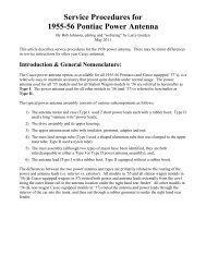
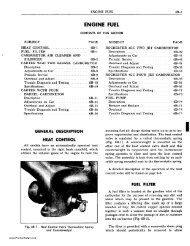
Fig. 9-23<br />
o<br />
OIL<br />
PRESSURE<br />
~:~~~-i:i!!!c:::. -:::o:til<br />
o<br />
ROTOR RING<br />
o<br />
ROTOR<br />
o<br />
Oil Flow in Rotor and Vanes in Rotor Ring<br />
through another passage in the pressure plate so that<br />
it may enter behind the rotor vanes to force the vanes<br />
to follow the contour of the rotor ring. The remainder<br />
of the oil is directed through an orifice in the pressure<br />
plate.<br />
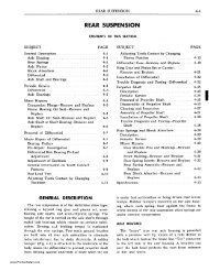
The orifice in the pressure plate is calibrated so<br />
that pump output in excess of 1.8 gallons per minute<br />
will cause a back pressure. This pressure will open<br />
the flow control valve. against spring force. allowing<br />
excess oil to return to the reservoir. When flow to the<br />
steering gear is restricted as when using power steering.<br />
the pressure on both sides of the flow control<br />
valve becomes equal and the flow control valve spring<br />
closes the valve. allowing pressure to increase to provide<br />
the force required for power steering.<br />
If oil pressure in the steering gear reaches 750-900<br />
psi. the pressure relief valve will open against spring<br />
force to limit maximum oil pressure. When the pressure<br />
relief valve opens. it allows oil in the pressure<br />
outlet passage to pass through the flow control valve<br />
to the reservoir.<br />
OUTLET ROTOR<br />
PORT RING<br />
ORIFICE (1.8 GAL. PER MIN.)<br />
Fig. 9-24<br />
Oil Flow in Pump With Low Car Speed and Partial Turn<br />
www.PontiacSafari.com
<strong>POWER</strong> <strong>STEERING</strong> 9-13<br />
drop and the flow control valve to open slightly, which<br />
in turn limits the pressure by allowing oil to return<br />
to the reservoir.<br />
The schematic diagram in Fig. 9-26 shows the operation<br />
of the flow control valve when the car is being<br />
driven at high speed. The pump output at high speed<br />
exceeds 1.8 gallons per minute and opens the flow<br />
control valve to let oil return to the reservoir. This<br />
occurs during turns as well as in straight ahead<br />
driving.<br />
ADJUSTMENTS ON CAR<br />
Fig. 9-25<br />
Oil Flow in Pump With Low Car Speed<br />
and Full "U" Turn<br />
The schematic diagram in Fig. 9-24 is typical of<br />
pump operation when the car is being driven at low<br />
speed during a partial turn. The oil pressure cannot<br />
become high enough to open the relief valve, because<br />
the spool valve in the steering gear is still partially<br />
open allowing some oil to return to the pump reservoir.<br />
Also, due to the low pump speed, the oil flow is<br />
not great enough to open the flow control valve.<br />
The schematic diagram in Fig. 9-25 is typical of<br />
pump operation when the car is being driven in a full<br />
"U" turn at low speed with wheels cramped against<br />
stops. In this case maximum pump pressure is being<br />
applied to the piston to assist in the turn and the<br />
spool valve stops the flow of oil to the reservoir. The<br />
high oil pressure that develops opens the pressure<br />
relief valve. The restricted orifice between the outlet<br />
passage and the valve chamber causes the pressure to<br />
HIGH<br />
Before any adjustments are made to the power<br />
steering gear in an attempt to correct such conditions<br />
as shimmy, hard or loose steering, and road shocks,<br />
a careful check should be made to determine that<br />
front end alignment, shock absorbers, wheel balance<br />
and tire pressure are correct.<br />
There are three major adjustments of the power<br />
steering gear which can be made on the car:<br />
1. PITMAN SHAFT END PLAY ADJUST<br />
MENT.<br />
2. <strong>POWER</strong> RACK GUIDE ADJUSTMENT.<br />
3. <strong>PUMP</strong> BELT TENSION ADJUSTMENT.<br />
PITMAN SHAFT END PLA Y ADJUSTMENT<br />
1. Disconnect steering connecting rod from pitman<br />
arm by removing cotter pin and plug from connecting<br />
rod.<br />
2. Loosen four power rack guide cover bolts. Do<br />
not loosen two center bolts.<br />
3. Loosen pitman shaft adjusting screw lock nut<br />
and back off adjusting screw a few turns, using an<br />
offset screwdriver.<br />
4. With steering gear "on center", adjust pitman<br />
shaft thrust screw (Fig. 9-27) so that pull on steering<br />
wheel rim through a 3" arc using J-S44-A spring<br />
scale, is 1 to 1 Y4 Ibs. through center. Turning screw<br />
clockwise increases pull, counterclockwise decreases<br />
pull.<br />
5. Tighten nut while holding screw with offset<br />
screwdriver and recheck pull at rim of steering wheel.<br />
Fig. 9-26<br />
FLOW<br />
CONTROL VALVE<br />
Oil Flow in Pump With High Car Speed<br />
<strong>POWER</strong> RACK GUIDE ADJUSTMENT<br />
After pitman shaft end play has been adjusted,<br />
clearance between power rack gear and ball nut must<br />
be adjusted to prevent binding or excessive lash at<br />
this point.<br />
www.PontiacSafari.com
9-14 1955 PONTIAC SHOP MANUAL<br />
51 TO 53 LBS. FT.<br />
TOOL J5574<br />
Fig. 9-27<br />
Adjusting Pitman Shaft End Play<br />
Fig. 9-28<br />
Adjusting Pump Belt Tension<br />
1. Make note of the final pull through center established<br />
by pitman shaft end play adjustment.<br />
2. Tighten four power rack guide cover bolts<br />
evenly.<br />
3. Again check pull at steering wheel, in "no lash"<br />
range or center position. Pull through a 3" arc at the<br />
rim is 1 % lb. maximum.<br />
4. If pull through "no lash" range increased in<br />
Step 2 above maximum, shims .003" thickness should<br />
be added under power rack guide cover until last<br />
shim added decreases load.<br />
5. If pull through "no lash" range remains the<br />
same in Step 2, shims of .003" thickness should be removed<br />
until load increases over that obtained in Step<br />
I, under Pitman End Play Adjustment. Then add one<br />
.003" shim to provide proper adjustment of power<br />
rack guide. CAUTION: Be sure bolt threads do not<br />
pick up shims when tightening cover to housing.<br />
COMPLETE <strong>GEAR</strong> ASSEMBLY<br />
The total over center load while rotating the steering<br />
shaft from the end of travel shall not exceed 2 lb.<br />
pull at the rim with spring scale. If pull exceeds 2 lb.,<br />
check thrust bearing adjustment as given on page<br />
9-21.<br />
<strong>PUMP</strong> BELT TENSION ADJUSTMENT<br />
Loosen pump to bracket bolts two full turns so<br />
pump falls of its own weight. Place pump belt tightener<br />
J-5574, over head of hinge bolt as shown in Fig.<br />
9-28. Using torque wrench perpendicular to tool,<br />
tighten a new belt 58-65 lb. ft. or a used belt 51-53<br />
lb. ft.<br />
Tighten clamp bolt. Remove tool and tighten<br />
mounting bolt.<br />
PERIODIC SERVICE<br />
RECOMMENDATIONS<br />
Periodic service consists of lubricating periodically<br />
as outlined in General Lubrication Section.<br />
REMOVAL OF <strong>POWER</strong> <strong>STEERING</strong><br />
<strong>GEAR</strong> FROM CAR<br />
NOTE: If car is equipped with power brakes<br />
refer to page 5-20 for removal of power brake<br />
unit.<br />
l. Hook front suspension in five passenger load<br />
position using tool J -5571 front suspension hold down<br />
hook (Fig. 9-29).<br />
2. Remove steering wheel using puller J-3044.<br />
www.PontiacSafari.com
<strong>POWER</strong> <strong>STEERING</strong> 9-15<br />
Fig. 9-29<br />
Hold Down Hook J-5571 Installed<br />
3. Remove direction signal switch handle and gearshift<br />
lever.<br />
4. Remove steering column to instrument panel<br />
bracket cap.<br />
5. Slide rubber grommet up steering column jacket.<br />
Roll back floor mat and remove pedal plates from<br />
floor.<br />
6. Remove neutralizer and back-up light switch on<br />
Hydra-Matic equipped cars.<br />
7. Disconnect gearshift and selector rods.<br />
8. Disconnect direction signal wires.<br />
9. Disconnect power steering oil lines at gear and<br />
secure lines so ends are higher than reservoir to prevent<br />
fluid leaking. Install plastic plugs or tape to<br />
cover gear and line openings and prevent entry of<br />
dirt.<br />
10. Protect all finished surfaces on steering column<br />
with masking tape.<br />
11. Raise car on hoist.<br />
12. Remove starter motor.<br />
13. Remove pitman arm.<br />
14. Remove left side tie rod end and drop steering<br />
linkage.<br />
15. Remove engine left side apron.<br />
Fig. 9-30 Steering Gear Mounted on Tool J-5205<br />
16. Remove brake pedal h,airpin spring retainer<br />
and slide pedal to right as far as it will go.<br />
17. If car is on a twin post hoist it will be necessary<br />
to place stands under both front frame ends and<br />
lower front post approximately three feet to allow<br />
steering assembly to clear hoist.<br />
18. Push steering connecting linkage down and toward<br />
rear of car, remove steering assembly to frame<br />
attaching bolts, removing front upper bolt last, and<br />
lower assembly between lower control arm and steering<br />
connecting linkage. NOTE: Check amount of<br />
shims and do not lose shims that are between steering<br />
gear housing and frame.<br />
19. Thoroughly clean exterior of steering gear.<br />
20. Mount holding fixture (1-5205) in vise or differential<br />
carrier holding stand (J -945) or (1-3289)<br />
and attach gear to fixture with three long bolts which<br />
are part of J-5205 (Fig. 9-30).<br />
21. Hydraulic fluid can be drained into a container<br />
by removing tape or plugs from elbows and turning<br />
gear through steering range several times. Lubricant<br />
in gear housing should also be drained into separate<br />
container.<br />
www.PontiacSafari.com
9-16 1955 PONTIAC SHOP MANUAL<br />
DISASSEMBLY OF<br />
<strong>POWER</strong> <strong>STEERING</strong> <strong>GEAR</strong><br />
REMOVAl. Of VAl.VE BODY fROM<br />
<strong>GEAR</strong> ASSEMBl. Y (fIG. 9-33'<br />
1. Remove two pipes from valve body and cylinder<br />
and small by-pass pipe from cylinder and gear housing.<br />
NOTE: Do not loosen line elbows unless seals<br />
are to be replaced because of leaks. Leaving fittings<br />
tight will aid when reassembling oil lines. It is not<br />
necessary to remove small brass fittings, one of<br />
which is located in power cylinder, and the other in<br />
valve body.<br />
2. Scribe mark cover, body, and gear housing to<br />
ensure same positioning of parts on reassembly<br />
(Fig. 9-31).<br />
3. Remove three valve cover to gear housing attaching<br />
screws and remove column jacket, gearshift<br />
controls and cover as an assembly. Remove large<br />
"0" ring seal and remove steering shaft seal from<br />
valve body cover if damaged.<br />
4. Cut out staked area from thrust bearing nut<br />
using a small chisel (nut should be discarded).'<br />
CAUTION: Remove all metal chips from keyway<br />
immediately.<br />
5. Turn steering shaft counterclockwise to end of<br />
travel and remove thrust bearing nut using tool<br />
J -5680, and remove spring washer, small bearing race,<br />
bearing and large bearing race.<br />
Fig. 9-31<br />
Scribe Marks on Cover, Body<br />
and Gear Housing<br />
4. Remove return line union and remove check<br />
valve from valve body, using screwdriver.<br />
REMOVAl. Of <strong>POWER</strong> CYLINDER ASSEMBl. Y<br />
fROM <strong>GEAR</strong> HOUSING (fIG. 9-33'<br />
1. Remove four outer power rack CQver to gear<br />
housing screws and remove power rack cover with<br />
guide spacing shims (Fig. 9-30). NOTE: Do not remove<br />
two bolts in center of cover.<br />
2. Remove side cover screws and adjusting screw<br />
nut. Turn adjusting screw down through cover to remove<br />
side cover from housing. Remove cover and<br />
gasket.<br />
6. With gear assembly in horizontal position, remove<br />
valve body and spool valve as an assembly,<br />
being careful not to lose plungers or springs from<br />
valve body (Fig. 9-32).<br />
7. Remove large bearing race, bearing and small<br />
bearing race.<br />
8. Remove "0" ring seal from gear housing upper<br />
flange if leaking or damaged.<br />
DISASSEMBl.Y Of VALVE BODY (fIG. 9-331<br />
1. A clean piece of paper should be laid on bench<br />
to protect valve body parts from foreign material.<br />
2. Slide spool valve out of body carefully so as 'not<br />
to nick or score valve or body.<br />
3. Remove ten plungers and five springs using care<br />
not to nick or score plUngers.<br />
Fig. 9-32<br />
Removing Valve Body and Spool Valve<br />
www.PontiacSafari.com
<strong>POWER</strong> <strong>STEERING</strong><br />
9-17<br />
52<br />
1<br />
2<br />
~ 411 f1<br />
4~ ~ )I ~<br />
6 1O~<br />
~ / 9 13 --~<br />
45 ~14<br />
():..15<br />
"-- 403B~<br />
'-C 3:~a9<br />
381' 33<br />
34<br />
16<br />
~ 17<br />
~~fJ<br />
26 25<br />
EXPLODED VIEW <strong>POWER</strong><br />
<strong>STEERING</strong> <strong>GEAR</strong><br />
1.<br />
2.<br />
3.<br />
4.<br />
5.<br />
6.<br />
7.<br />
8.<br />
9.<br />
10.<br />
11.<br />
12.<br />
13.<br />
14.<br />
15.<br />
Power Cylinder<br />
16. Steering Gear Housing<br />
Cylinder Gasket<br />
Worm Bearing<br />
Piston Rings<br />
17. Steering Gear Housing<br />
Power Cylinder Piston<br />
Worm Seal<br />
"0" Ring Seals 18. Bellville Washer 25.<br />
Power Cylinder Adopter 19. Thrust Bearing Nut 26.<br />
Power Rock Stop Plate 20. "0" Ring Seal 27.<br />
Piston Rod to Rock 21. Valve Cover Seal 28.<br />
Retainer Pin 22. Valve Body Cover 29.<br />
Power Rock<br />
23. Thrust Bearing Assembly<br />
Power Rock Cover Shims 24. Valve Body Assembly 30.<br />
Power Rock Guide A. Return line Union 31.<br />
Power Rock Cover B. "0" Ring Seal 32.<br />
Steering Gear Housing C. Check Valve 33.<br />
Pitman Shaft Seal D. Valve Body 34.<br />
Retainer E. Spool Valve 35.<br />
Pitman Shaft Seal F. Spring 36.<br />
G. Plungers 37.<br />
H. "0" Ring Seal<br />
I. Universal Elbow Bolt<br />
J. Universal Elbow<br />
K. "0" Ring Seal<br />
Thrust Bearing Assembly<br />
"0" Ring Seal<br />
Bushing<br />
Housing Vent<br />
Pitman Shaft Adjusting<br />
Screw<br />
Boll Nut Guide<br />
Steering Shaft<br />
Boll Nut<br />
Boll Nut Guide Clomp<br />
Adjusting Screw Nut<br />
Housing Side Cover<br />
Adjusting Screw Shim<br />
Side Cover Gasket<br />
38. Pitma n Shaft<br />
39. End Cover Worm Bearing<br />
40. End Cover Gasket<br />
41. End Cover<br />
42. By-Pass Pipe<br />
43. Valve to Bose<br />
of Cylinder Pipe<br />
44. Valve to Head<br />
of Cylinder Pipe<br />
45. Piston Rod<br />
46. Thrust Washer<br />
47. Thrust Washer<br />
48. Piston Rod Lock Nut<br />
49. Universal Elbows<br />
50. "0" Ring Seals<br />
51. Universal Elbow Bolts<br />
52. "0" Ring Seals<br />
Fig. 9-33<br />
Power Steering Gear-Exploded View<br />
www.PontiacSafari.com
9-18 1955 PONTIAC SHOP MANUAL<br />
3. Remove adjusting screw from slot in pitman<br />
shaft. Make sure shim found on adjusting screw is<br />
kept with screw.<br />
4. Remove pitman shaft and gear from housing<br />
using caution to prevent splines from damaging pitman<br />
shaft seal in housing.<br />
END COVER<br />
5. Scribe mark on cylinder and housing and remove<br />
cylinder to gear housing screws. Remove cylinder and<br />
gasket, guiding power rack through hole in housing.<br />
DISASSEMBL Y OF CYLINDER (FIG. 9-33)<br />
TOOL J·5190<br />
1. Place power rack in a vise with jaws against<br />
sides of rack and pull cylinder off adapter and piston<br />
assembly (Fig. 9-34). Do not place machined surfaces<br />
of rack in jaws.<br />
2. With power rack still in vise, remove piston rod<br />
lock nut, thrust washer, piston with rings, thrust<br />
washer, and adapter assembly.<br />
3. Remove stop plate from adapter assembly.<br />
4. Remove large "0" ring seals from adapter if<br />
necessary to replace.<br />
5. Remove piston rod seal from adapter if defective.<br />
Fig. 9-35<br />
Removing Bearing From End Cover<br />
<strong>POWER</strong> CYLINDER<br />
Fig. 9-36<br />
Removing Steering Shaft and Ball Nut<br />
4. Remove guide clamp, guides and balls from ball<br />
nut and remove ball nut from steering shaft.<br />
Fig. 9-34<br />
Removing Cylinder From Adapter and Piston<br />
DISASSEMBL Y OF <strong>STEERING</strong> <strong>GEAR</strong><br />
HOUSING (FIG. 9-33)<br />
1. Remove three end cover attaching screws and<br />
remove cover with roller bearing and gasket.<br />
2. Using puller tool J-SI90, remove roller bearing<br />
from end cover (Fig. 9-35), if it is to be replaced.<br />
3. Slide steering shaft and ball nut, as an assembly,<br />
out of gear housing (Fig. 9-36).<br />
5. Remove steering gear housing worm bearing if<br />
it is to be replaced, by driving bearing down from<br />
upper end of housing.<br />
6. Remove pitman shaft seal from housing if damaged.<br />
7. If replacement is required, remove worm bearing<br />
seal from housing upper flange with offset screwdriver<br />
(Fig. 9-37).<br />
INSPECTION OF PARTS<br />
1. Wash all parts in clean kerosene or other cleaning<br />
solvent.<br />
www.PontiacSafari.com
<strong>POWER</strong> <strong>STEERING</strong> 9-19<br />
TOOL J·5189<br />
(BRG. END)<br />
Fig. 9-37<br />
Removing Seal From Housing Upper Flange<br />
Fig. 9-38<br />
Installing Seal in Housing Upper Flange<br />
2. Inspect bearings, bushings, seals, teeth, for scoring,<br />
wear, pitting, etc., which would necessitate replacement.<br />
3. All "0" ring seals and gaskets should be carefully<br />
inspected and replaced if necessary.<br />
4. Inspect power rack and piston rod assembly to<br />
ensure that link pin is securely staked.<br />
5. Install 21 balls in each circuit of ball nut (rock<br />
steering shaft slightly to aid in installing balls) and<br />
install 9 balls in each return guide using petrolatum<br />
to hold balls in place. Install return guides, clamp<br />
and screw. CAUTION: Do not rotate shaft while installing<br />
balls, since balls may enter crossover passage<br />
between circuits. This will cause improper operation<br />
of ball nut.<br />
ASSEMBLY OF <strong>POWER</strong><br />
<strong>STEERING</strong> <strong>GEAR</strong><br />
ASSEMBL Y Of <strong>GEAR</strong> HOUSING (fiG. 9-JJJ<br />
NOTE: Steps 1-3 apply only if seal and bearings<br />
are being replaced. All seals and bearings should<br />
be pre-lubricated before installation.<br />
1. Install new seal in housing upper flange using<br />
tool J-5189 (Fig. 9-38). Use soft hammer to prevent<br />
damage to tool.<br />
TOOL )-5189<br />
(SEAL END)<br />
2. Install new bearing in housing using soft hammer<br />
(to avoid damaging tool) and installing tool<br />
J-5l89 (Fig. 9-39). (Side of bearing with trademark<br />
should be against tool.)<br />
3. Press new bearing into end cover using tool<br />
1-5191 (Fig. 9-40). (End with trademark should be<br />
up.)<br />
4. Position ball nut on shaft with teeth up so wide<br />
or large spaces are toward you when upper end of<br />
shaft is toward your right (Fig. 9-41).<br />
Fig. 9-39<br />
Installing Bearing in Housing<br />
www.PontiacSafari.com
9-20 1955 PONTIAC SHOP MANUAL<br />
INSTAllATION OF VALVE BODY<br />
<strong>AND</strong> COVER (FIG. 9-33J<br />
1. Install small bearing race, bearing, and large<br />
bearing race on steering shaft.<br />
2. Install new "0" ring seal in groove in housing<br />
flange, if removed.<br />
3. Slide valve body assembly over steering shaft<br />
with counterbored end of spool valve and lettering on<br />
oil line bosses toward upper end of shaft.<br />
4. Install plungers and springs in valve body; finished<br />
surfaces of plungers should face outside of body.<br />
Fig. 9-40<br />
LOWER END<br />
..<br />
Installing Bearing in End Cover<br />
DEEP SIDE OF TEETH<br />
Some early production 1955 power steering gears<br />
will be equipped with 1954 valve assemblies. The<br />
valve centering springs and plungers are also interchangeable;<br />
that is, 1954 springs and plungers may<br />
be used as replacement parts in 1955 valve assemblies<br />
and viCe-versa.<br />
Because of the difference in lengths of springs and<br />
plungers for these two years it is imperative that these<br />
parts be replaced in sets. A "set" in this instance<br />
means two plungers and one spring.<br />
The part numbers, lengths, and identification features<br />
of the springs and plungers for 1954 and 1955<br />
are given in Fig. 9-43.<br />
5. Align scribe marks on body with scribe marks<br />
on housing, place valve body retaining collar J-5182<br />
over valve body, install valve body to housing screws,<br />
and tighten (Fig. 9-44).<br />
Fig. 9-41<br />
Ball Nut Properly Installed on Shaft<br />
6. Run ball nut to upper end of worm, then slide<br />
steering shaft and nut into housing with tool J-5210<br />
in place on upper threads of steering shaft to protect<br />
upper housing seal (Fig. 9-42).<br />
7. Install end cover with gasket on housing and<br />
tighten screws.<br />
ASSEMBLY OF VALVE BODY (FIG. 9-33J<br />
1. Install check valve in return line of valve body.<br />
Install "0" rings on return line union and install<br />
union in valve body.<br />
2. Place valve body on table so that lettering on<br />
bosses for oil lines faces up.<br />
3. Very carefully install spool valve in body with<br />
shallow, counterbored end of spool up. (When installed<br />
on steering gear, this end must be toward<br />
steering wheel.)<br />
Fig. 9-42<br />
Tool J-5210 Installed on Steering Shaft<br />
www.PontiacSafari.com
<strong>POWER</strong> <strong>STEERING</strong> 9-21<br />
1954<br />
T<br />
ZINC PLATE<br />
DICHROMATE FINISH ~~<br />
GREENISH WHITE .660<br />
TO BRONZE-LIKE<br />
1<br />
COLOR<br />
5665555<br />
IDENTIFICATION.CJ OR q<br />
GROOVE U tj<br />
5663828<br />
1955<br />
5683101<br />
T<br />
PLAIN<br />
.760<br />
1<br />
STEEL<br />
FINISH<br />
ONO IDENTIFICATION<br />
GROOVE<br />
5665638<br />
Fig. 9-43<br />
Comparison of 1954 and 1955 Power Steering Valve Centering Springs and Plungers<br />
6. Install large bearing race, bearing, and small<br />
bearing race against valve body.<br />
7. Install special spring type washer with concave<br />
face toward bearing and thrust bearing nut loosely.<br />
Use new nut.<br />
8. Worm Bearing Adjustment.<br />
a. Install steering wheel and turn counterclockwise<br />
to stop. Maintain constant pressure on the wheel to<br />
compress plunger springs.<br />
b. Tighten locknut against spring washer (and<br />
spool valve) 20 to 30 lb. ft. torque, making sure the<br />
thrust bearings are properly seated and then back<br />
off nut Y4 to % turn and stake in place. Use crowfoot<br />
wrench tool J -5680 and torque wrench (Fig. 9-45).<br />
To check bearings rotate the gear in each direction,<br />
observing for freedom of movement. Any bind or drag<br />
is indicative of improperly seated bearings.<br />
The pull at the rim of the steering wheel to turn<br />
steering shaft through a 3" arc at the rim will be<br />
approximately Y2 to % lb. This includes seal drag.<br />
c. Remove steering wheel and remove retaining<br />
collar J-5182 from valve body.<br />
seal was removed.<br />
11. Install valve cover, column jacket and gearshift<br />
controls as an assembly. Be sure parts are lined up<br />
as indicated by scribed marks on housing, body and<br />
cover, and install cover attaching screws.<br />
ASSEMBL Y OF <strong>POWER</strong> CYLINDER (FIG. 9-33)<br />
1. Install new seal in adapter if seal was removed.<br />
2. Install "0" ring seals on adapter, if removed.<br />
3. Slide stop plate over piston rod.<br />
9. Install new seal in valve body cover, if seal was<br />
removed, using tool J-5188 (Fig. 9-46).<br />
10. Install "0" ring seal in valve body cover, if<br />
Fig. 9-44<br />
Installing Tool J-5182 on Valve Body Cylinder<br />
www.PontiacSafari.com
9-22 1955 PONTIAC SHOP MANUAL<br />
Fig. 9-47<br />
Installing Adapter on Piston Rod<br />
Fig. 9-45<br />
Adjusting Thrust Bearing Nut<br />
Using Tool J-5680<br />
4. Install tool J -5193 over threaded end of piston<br />
rod and slide adapter over piston rod (Fig. 9-47).<br />
Remove tOQl.<br />
S. Install thrust washer on piston rod.<br />
6. Install piston assembly on rod (either side out).<br />
7. Install thrust washer and nut on piston rod and<br />
tighten securely with rack in vise. Vise jaws should<br />
be against sides of rack.<br />
8. Install piston and adapter assembly into cylinder<br />
using tool J-SI68-A to compress piston rings (Fig.<br />
9-48). Hold adapter against power rack while installing<br />
piston to prevent ring compressor from cutting<br />
"0" ring seals. NOTE: Position ring gaps on opposite<br />
sides of piston.<br />
9. Remove ring compressor and carefully slide<br />
adapter with seals into cylinder.<br />
10. Push power rack and piston assembly into cylinder<br />
as far as possible.<br />
<strong>POWER</strong> CYLINDER<br />
Fig. 9-46<br />
Installing Seal in Valve Body Cover<br />
Fig. 9-48<br />
Installing Piston and Adapter in Cylinder<br />
www.PontiacSafari.com
<strong>POWER</strong> <strong>STEERING</strong> 9-23<br />
INSTALLATION OF CYLINDER ASSEMBLY ON<br />
<strong>GEAR</strong> HOUSING (fiG. 9-33J<br />
1. Place gasket on cylinder and guide power rack<br />
through opening in gear housing with teeth on rack<br />
pointing toward center of housing.<br />
<strong>POWER</strong> RACK<br />
2. With scribe marks on cylinder and housing<br />
aligned, install cylinder to housing attaching screws.<br />
3. Turn steering wheel clockwise to run ball nut to<br />
upper end of its travel.<br />
4. Install pitman shaft seal in housing if seal was<br />
removed.<br />
5. Install pitman shaft in housing with tapered<br />
teeth contacting ball nut, engage first tooth of gear<br />
with first tooth of power rack and worm gear ball nut<br />
as shown in Fig. 9-49.<br />
6. Install pitman shaft adjusting screw with shim<br />
in slot of pitman shaft. Fit of adjusting screw in slot<br />
should be from no play to .002" loose. If end play of<br />
screw in slot is incorrect, select new shim to give<br />
proper clearance. Shims are furnished in four thicknesses<br />
(.063", .065", .067", .069").<br />
7. Install side cover with gasket on adjusting screw,<br />
turning screw counterclockwise until it projects<br />
through cover %" to %" with cover seated against<br />
housing.<br />
8. Install cover attaching screws.<br />
9. Install adjusting screw nut loosely.<br />
10. Install power rack guide, with same number of<br />
spacing shims as were removed, and leave attaching<br />
screws loose.<br />
11. Connect by-pass pipe to fittings in cylinder and<br />
gear housing flange.<br />
12. Install cylinder to valve body pipes. Use new<br />
"0" ring seals at each elbow if replacement was necessary<br />
and tighten elbow bolts to 20-30 lb. ft. torque.<br />
13. Adjust pitman shaft end play (page 9-13).<br />
14. Adjust power rack guide (page 9-13).<br />
INSTALLATION OF <strong>POWER</strong><br />
<strong>STEERING</strong> <strong>GEAR</strong> IN CAR<br />
1. With hairpin spring retainer removed, move<br />
brake pedal as far to right as it will go.<br />
2. Push steering connecting linkage down and toward<br />
rear and install steering gear assembly by guiding<br />
between lower control arm and steering connect-<br />
Fig. 9-49<br />
Pitman Shaft Correctly Installed<br />
ing linkage. Remove tool J-SS71 hold down hook.<br />
3. Install top front steering gear housing to frame<br />
bolt with lockwasher finger tight. CAUTION: Be<br />
sure to install shims which were between steering<br />
gear housing and frame when unit was removed.<br />
4. Install steering column lower bracket with lockwashers<br />
and bolts to upper bracket on instrument<br />
panel.<br />
S. Install two remaIning steering gear housing to<br />
frame bolts with plain and lockwashers and tighten<br />
all three bolts.<br />
6. Check for correct shimming of steering gear<br />
housing to frame by seeing if steering column aligns<br />
with upper bracket when bracket bolts are loosened.<br />
If alignment is correct, tighten steering column<br />
bracket bolts. NOTE: If misalignment exists, it will<br />
be necessary to change steering gear housing to frame<br />
shims to correct alignment.<br />
7. Position brake pedal and install hairpin retaining<br />
spring.<br />
8. Connect direction signal wires.<br />
9. Connect power steering oil lines to gear.<br />
10. Connect gear shift and selector rods.<br />
11. Install engine left side pan.<br />
12. Install pitman arm and secure with lockwasher<br />
and nut. Tighten nut to 110 to 125 lb. ft. torque.<br />
13. Install starter motor.<br />
www.PontiacSafari.com
9-24 1955 PONTIAC SHOP MANUAL<br />
14. Install neutralizer and back-up light switch on<br />
Hydra-Matic equipped cars.<br />
15. Install pedal plates, floor mat and position<br />
steering column jacket rubber grommet on floor.<br />
16. Install direction signal switch handle and gearshift<br />
lever.<br />
17. Install steering wheel.<br />
18. Fill steering gear housing with All-Season<br />
Steering Gear Lubricant.<br />
19. Check fluid level In pump reservoir. Fluid<br />
should be up to mark near top of reservoir. If not,<br />
add Hydra-Matic Fluid or Automatic Transmission<br />
Fluid identified by an AQ-A TF qualification number.<br />
Start engine and bleed hydraulic system by manually<br />
steering through cycles several times (with front<br />
wheels off floor) until there is no evidence of air<br />
bubbles in reservoir. Recheck fluid level.<br />
REMOVAL OF <strong>PUMP</strong> FROM CAR<br />
1. Cover generator to protect it from accidental<br />
spillage of oil.<br />
2. Remove reservoir cover attaching bolt, lockwasher,<br />
and plain washer, and remove reservoir cover<br />
and gasket. Use care not to lose bolt guide and gasket.<br />
3. Remove oil in pump reservoir.<br />
4. Disconnect lines if not done in Step 3 and secure<br />
ends of lines up high to avoid spilling oil.<br />
S. Remove pulley to pump shaft attaching nut and<br />
washer. Hold pulley hub with 10/16" open end wrench.<br />
6. Loosen two bolts attaching pump to bracket. Remove<br />
pulley. NOTE: Do not remove key from shaft<br />
unless damaged.<br />
7. Remove pump to bracket attaching bolts and<br />
remove pump from car.<br />
PLAIN WASHER ----!<br />
BOLT---l<br />
RESERVOIR COVER ~<br />
SCREW <strong>AND</strong> __ --"' ...<br />
LOCKWASHER<br />
RESERVOIR<br />
r FLOW<br />
BOLT<br />
BOLT<br />
~QWa'<br />
SEAL<br />
SPRINGJ /<br />
CONTROL VALVE ASSY.<br />
PRESSURE PLATE<br />
Fig. 9-50<br />
Power Steering Pump-Exploded View<br />
www.PontiacSafari.com
<strong>POWER</strong> <strong>STEERING</strong> 9-25<br />
DISASSEMBLY OF <strong>PUMP</strong><br />
Clean exterior of pump using care to prevent dirt<br />
and foreign material from entering pump. A clean<br />
sheet of paper should be used on bench to keep pump<br />
parts clean.<br />
1. Remove reservoir body from pump body and<br />
cover (Fig. 9-50). Use care not to lose spacers and<br />
reservoir to body and cover gaskets.<br />
2. Remove four pump cover to pump body attaching<br />
bolts, and carefully remove pump cover with flow<br />
control valve and spring.<br />
3. Lift pressure plate off dowel pins extending<br />
through rotor ring and remove rotor ring "0" ring<br />
seal.<br />
4. Remove rotor ring from dowel pins and remove<br />
rotor, vanes and second rotor ring "0" ring seal.<br />
Remove dowel pins from pump body.<br />
S. Remove outer bearing snap ring from groove<br />
in pump body using tool J -4245.<br />
6. Properly support pump body and remove drive<br />
shaft and outer bearing by tapping on end with soft<br />
hammer.<br />
7. If drive shaft seal or inner bearing is to be replaced,<br />
seal must be removed using a punch. The<br />
inner bearing is removed by lightly tapping on inner<br />
race.<br />
8. Disassemble flow control and relief valve, maintaining<br />
pressure on spring loaded plug to prevent loss<br />
of poppet ball. Use care not to score ground surfaces<br />
of flow control valve (Fig. 9-51).<br />
9. Union fittings in cover should only be removed<br />
if "0" ring seals leak or fittings are damaged.<br />
CLEANING <strong>AND</strong> INSPECTION OF<br />
<strong>PUMP</strong> PARTS<br />
1. Wipe bearing and shaft assembly with clean<br />
cloth; do not soak in cleaning solvent as the lubricant<br />
sealed into bearing may be diluted by solvent. Wash<br />
all other parts in clean kerosene or other solvent and<br />
wipe dry with clean lint-free cloth.<br />
2. Inspect drive shaft for wear and check both ball<br />
bearings for roughness or noisy operation. If outer<br />
bearings must be replaced, press off shaft with tool<br />
J-SS73 (Fig. 9-52).<br />
3. Check fit of vanes in slots of rotor; vanes must<br />
slide freely but snugly in slots. Tightness may be<br />
'r-"<br />
POPPET SPRING<br />
BALL<br />
J<br />
'LUG \ ~<br />
'<br />
1 r"""\o9'~ VALVE<br />
~ GUIDE<br />
SHIM WASHERS<br />
CALIBRATED ORIFICE<br />
fig. 9-51<br />
fig. 9-52<br />
flow Control Valve-Exploded View<br />
Installing Outer Bearing on Shaft<br />
relieved by thorough cleaning, or removal of irregularities.<br />
Replace rotor if excessive looseness exists<br />
between rotor and vanes, and replace vanes if worn<br />
or scored.<br />
4. Inspect all ground surfaces of rotor ring for<br />
roughness or irregular wear. Slight irregularities may<br />
be removed with a hard stone. Replace ring if inside<br />
cam surface is scored or worn.<br />
S. Inspect flat faces of the pressure plate and<br />
pump body for wear or scoring. Light scores may be<br />
smoothed by lapping, after which all lapping compound<br />
must be thoroughly washed away.<br />
6. Inspect ground surfaces of flow control valve,<br />
paying particular attention to seating surfaces. Check<br />
freedom of movement of flow control valve within its<br />
bore. Slight irregularities may be corrected by lapping<br />
or polishing.<br />
7. Inspect all passages in cover and body for obstructions<br />
or dirt.<br />
www.PontiacSafari.com
9-26 1955 PONTIAC SHOP MANUAL<br />
ASSEMBLY OF <strong>PUMP</strong><br />
Before assembling, make sure all parts are absolutely<br />
clean, and lubricate all moving parts with clean<br />
Hydra-Matic fluid. All "0" ring seals remov:od should<br />
be discarded.<br />
1. Install inner bearing (Fig. 9-50) in pump body<br />
by tapping lightly on bearing outer race.<br />
2. Position new drive shaft seal in body, being sure<br />
the chamfered side (side with two %6" holes) is facing<br />
out. NOTE: Use a pipe or shaft 1%" in diameter<br />
to apply pressure to outer edge of seal during installation.<br />
Apply a small amount of Hydra-Matic fluid to<br />
lip of seal.<br />
3. If removed, install outer bearing on shaft using<br />
tool J-5573 (Fig. 9-52).<br />
4. Install shaft and bearing assembly in pump body<br />
using care to avoid damaging lip of seal. Tap lightly<br />
on outer race of outer bearing until bearing is seated<br />
and install snap ring with flat side of snap ring<br />
against outer bearing race.<br />
5. Install dowel pins in pump body.<br />
6. Install rotor over splines on drive shaft and<br />
assemble vanes in rotor with radius edge outward.<br />
7. Install new rotor ring "0" ring seal in groove of<br />
pump body. Carefully position rotor ring over rotor<br />
and vanes. CAUTION: Arrows on rotor ring must be<br />
pointing in a clockwise direction when ring is assembled<br />
to pump body and viewed from the front.<br />
8. Position pressure plate over dowel pins and on<br />
rotor ring.<br />
9. Place new rotor ring "0" ring seal around pressure<br />
plate surface of rotor ring.<br />
10. Assemble flow control and relief valve (Fig.<br />
9-51). Be sure to install all shim washers which were<br />
originally used, as altering shim thickness will change<br />
relief pressure.<br />
11. Install flow control valve spring and valve in<br />
pump cover and assemble cover to body with four<br />
attaching bolts. Tighten to 25-30 lb. ft. torque.<br />
12. If removed, install new "0" ring seals on union<br />
fittings and install fittings.<br />
13. Position cork gaskets with spacers on pump<br />
body and cover, and install reservoir. Secure reservoir<br />
with four hex-head screws and tighten to 3%-4<br />
lb. ft. torque.<br />
14. Install reservoir cover gasket, cover, and secure<br />
with vent washer and reservoir cover attaching bolt.<br />
Plug or mask union fittings. These precautions are<br />
taken to exclude dirt or foreign material from pump<br />
until it is installed.<br />
INSTALLATION OF <strong>PUMP</strong> ON CAR<br />
1. Position pump on pump bracket and install two<br />
attaching bolts with plain washers and lockwashers,<br />
but do not tighten bolts.<br />
2. Install new key if required and slide pulley on<br />
shaft and secure with washer and self-locking nut.<br />
Hold pulley hub with 11%6" open end wrench and<br />
tighten nut to 50-55 lb. ft. torque.<br />
3. Remove plug or masking from union fittings and<br />
connect oil lines to fittings.<br />
4. Position pump drive belt over pulley and adjust<br />
pump belt tension (page 9-14).<br />
5. Refill with fluid and cycle steering several times<br />
to discharge air from system.<br />
TROUBLE DIAGNOSIS <strong>AND</strong> TESTING<br />
Before performing diagnosis, oil level in pump reservoir<br />
should be checked with engine idling after<br />
steering has been cycled several times. Oil level should<br />
be up to mark on side of reservoir. If low add Hydra<br />
Matic Fluid or Automatic Transmission Fluid identified<br />
by an AQ-A TF qualification number.<br />
<strong>STEERING</strong> KNOCKS WHILE TURNING<br />
WITH ENGINE RUNNING<br />
Improper pitman shaft adjustment.<br />
Improper power rack adjustment.<br />
Improper thrust bearing adjustment.<br />
<strong>STEERING</strong> WHEE!. SURGES OR JERKS WHEN<br />
TURNING WITH ENGINE RUNNING<br />
Loose pump belt.<br />
NOISY <strong>PUMP</strong> AfTER REFILLING RESERVOIR<br />
Air in system, bleed by lifting wheels off floor and<br />
turning through several cycles. Be sure pump pulley<br />
to shaft nut or bolt is properly tightened.<br />
NOTE: Cycling may not discharge all air immediately<br />
and pump will be noisy until entire system<br />
has been freed of trapped air.<br />
www.PontiacSafari.com
<strong>POWER</strong> <strong>STEERING</strong> 9-27<br />
WATER IN FLUID<br />
Should the fluid be cloudy, i.e., have the appearance<br />
of a mixture of coffee with cream, it is due to<br />
water being in the system. Once water is in the system<br />
there is no way to clarify the fluid so it is necessary<br />
that the fluid be replaced. This can best be done<br />
by removing the pump return pipe or flexible hose<br />
and catching the discarded fluid in a container. Pump<br />
the system as clear as possible, then fill with new<br />
fluid and cycle the steering from extreme right to extreme<br />
left and in this way force out all of the contaminated<br />
fluids. When the fluid being pumped<br />
through the return hose shows clean of this clouded<br />
mixture, connect the hose to the pump, fill the reservoir<br />
and again cycle the unit while the pump is operating<br />
until there is no evidence of air bubbles in the<br />
reservoir. Again fill the reservoir to level and install<br />
cover.<br />
HARD <strong>STEERING</strong> WHEN PARKING<br />
When engine is idling, car stopped, and steering<br />
wheel is turned in an effort to park, normal effort<br />
required at steering wheel rim is approximately 10<br />
pounds with oil at normal operating temperature of<br />
approximately 170°.<br />
Temperature will build up if steering wheel is<br />
turned from side to side with car standing. Therefore,<br />
if a complaint of hard steering when parking is encountered,<br />
carefully follow procedure below:<br />
Simulate parking by applying hand brake and turning<br />
wheels on a clean dry service floor. If effort<br />
exceeds 10 pounds (with 150° to 170° oil temperature)<br />
when checked with spring scale J-5178, make<br />
the following checks:<br />
1. Check pump drive belt tension and adjust as<br />
outlined on page 9-14.<br />
2. Check for lack of lubrication In steering gear,<br />
linkage and front suspension.<br />
3. Test tires for proper inflation and inflate to<br />
recommended pressures.<br />
4. Check tie rod and connecting rod ball seats for<br />
being too tight.<br />
5. Check steering gear adjustments for being tight.<br />
Adjust accordingly.<br />
6. Spot check all lines and gear for signs of leakage.<br />
7. If the above mentioned checks and their corrections<br />
do not eliminate the difficulty, perform pressure<br />
test.<br />
Fig. 9-53<br />
PRESSURE CHECK<br />
TEST NO.1<br />
Pressure Gauge J-5176 Installed<br />
1. Install 0-1000 pound gauge, tool J-5176, in pressure<br />
line between pump and gear (Fig. 9-53). Turn<br />
valve to "open" position.<br />
2. Turn steering wheel from one stop to the other<br />
and note pressure on gauge while turning wheel.<br />
Especially note maximum pressure that can be built<br />
up with steering wheel held momentarily in either<br />
extreme right or extreme left position. This maximum<br />
pressure reading should not be less than 650 lbs. with<br />
engine idling at 375 RPM, and oil temperature in reservoir<br />
between 150° to 170°. NOTE: To obtain temperatures<br />
of 150° to 170° desired for testing, turn<br />
wheels through normal operating range several times.<br />
CAUTION: DO NOT HOLD steering wheel against<br />
stop for an extended period of time.<br />
If maximum pressure is below 650 lbs., it indicates<br />
there is some trouble in hydraulic circuit; however,<br />
it does not indicate whether pump or gear is at fault.<br />
To determine if pump alone or gear alone or if both<br />
are at fault, proceed with TEST NO.2.<br />
TEST NO.2<br />
1. With engine idling at 375 RPM, turn shut-off<br />
valve of gauge J-5176 to closed position.<br />
2. Observe and compare maximum pump pressure<br />
at idle when turning wheel to extreme left and right.<br />
It should not be less than 650 lbs. NOTE: By comparing<br />
this reading with TEST NO.1, it is possible to<br />
determine whether fault is with pump or steering<br />
gear, or both as follows:<br />
www.PontiacSafari.com
9-28<br />
1955 PONTIAC SHOP MANUAL<br />
TEST RESULTS<br />
DIAGNOSIS<br />
1. First Test-below 650 Ibs. Defective steering<br />
Second Test-normal<br />
gear<br />
650 lbs. minimum<br />
2. First Test-below 650 lbs. Defective pump<br />
Second Test-not more than<br />
50 lbs. greater than first test.<br />
3. First Test-below 650 lbs. Defective steering<br />
Second test-more than 50 lbs. gear and pump<br />
greater than first test, but<br />
below 150 Ibs.<br />
TORQUE SPECIFICATIONS<br />
Tie rod clamp nuts<br />
Idler lever nut and bushing<br />
Steering gear pitman arm nut<br />
Steering wheel to shaft nut<br />
Reservoir to pump body screws<br />
Pump belt tension<br />
Pulley hub to pump shaft nut<br />
(Vane type)<br />
Pump cover bolts<br />
Lb. Ft. Torque<br />
18-20<br />
100<br />
110-125<br />
25-30<br />
3.5-4.0<br />
Page 9-14<br />
50-55<br />
8-10<br />
SPECIFICATIONS (<strong>POWER</strong> <strong>STEERING</strong>)<br />
Type<br />
Pump<br />
Pull at steering wheel<br />
Steering jacket diameter<br />
Saginaw Recirculating Ball Nut<br />
.... Rotor type (1953 and early 1954) Vane type (1954)<br />
10 lbs. maximum<br />
2%"<br />
Steering gear ratio ............. .<br />
19.1 :1<br />
Gear mesh adjustment<br />
Shims<br />
Lubricant level-Pump (Hydra-Matic fluid)<br />
Fill to filler line on reservoir<br />
Lubricant level-Steering gear<br />
Fill to bottom of filler plug hole<br />
Lubricant capacity-Steering gear . . . . . . . 24 fluid oz.<br />
www.PontiacSafari.com
<strong>POWER</strong> <strong>STEERING</strong> 9-29<br />
l<br />
J-5178<br />
J-1025<br />
J-3044<br />
Q J-4493<br />
J-5574<br />
~<br />
J-5176<br />
J-544A<br />
4\<br />
J-5188<br />
J-5189<br />
J-4245<br />
'ID ,'iSM? ;'$',<br />
V A V<br />
;
10-0 1955 PONTIAC SHOP MANUAL<br />
SERVICE CRAFfSMAN NEWS REFERENCE<br />
News News Page<br />
Year No. No.<br />
Subject<br />
.<br />
www.PontiacSafari.com