Create successful ePaper yourself
Turn your PDF publications into a flip-book with our unique Google optimized e-Paper software.
<strong>POWER</strong> <strong>STEERING</strong> 9-25<br />
DISASSEMBLY OF <strong>PUMP</strong><br />
Clean exterior of pump using care to prevent dirt<br />
and foreign material from entering pump. A clean<br />
sheet of paper should be used on bench to keep pump<br />
parts clean.<br />
1. Remove reservoir body from pump body and<br />
cover (Fig. 9-50). Use care not to lose spacers and<br />
reservoir to body and cover gaskets.<br />
2. Remove four pump cover to pump body attaching<br />
bolts, and carefully remove pump cover with flow<br />
control valve and spring.<br />
3. Lift pressure plate off dowel pins extending<br />
through rotor ring and remove rotor ring "0" ring<br />
seal.<br />
4. Remove rotor ring from dowel pins and remove<br />
rotor, vanes and second rotor ring "0" ring seal.<br />
Remove dowel pins from pump body.<br />
S. Remove outer bearing snap ring from groove<br />
in pump body using tool J -4245.<br />
6. Properly support pump body and remove drive<br />
shaft and outer bearing by tapping on end with soft<br />
hammer.<br />
7. If drive shaft seal or inner bearing is to be replaced,<br />
seal must be removed using a punch. The<br />
inner bearing is removed by lightly tapping on inner<br />
race.<br />
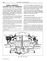
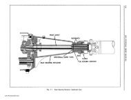
8. Disassemble flow control and relief valve, maintaining<br />
pressure on spring loaded plug to prevent loss<br />
of poppet ball. Use care not to score ground surfaces<br />
of flow control valve (Fig. 9-51).<br />
9. Union fittings in cover should only be removed<br />
if "0" ring seals leak or fittings are damaged.<br />
CLEANING <strong>AND</strong> INSPECTION OF<br />
<strong>PUMP</strong> PARTS<br />
1. Wipe bearing and shaft assembly with clean<br />
cloth; do not soak in cleaning solvent as the lubricant<br />
sealed into bearing may be diluted by solvent. Wash<br />
all other parts in clean kerosene or other solvent and<br />
wipe dry with clean lint-free cloth.<br />
2. Inspect drive shaft for wear and check both ball<br />
bearings for roughness or noisy operation. If outer<br />
bearings must be replaced, press off shaft with tool<br />
J-SS73 (Fig. 9-52).<br />
3. Check fit of vanes in slots of rotor; vanes must<br />
slide freely but snugly in slots. Tightness may be<br />
'r-"<br />
POPPET SPRING<br />
BALL<br />
J<br />
'LUG \ ~<br />
'<br />
1 r"""\o9'~ VALVE<br />
~ GUIDE<br />
SHIM WASHERS<br />
CALIBRATED ORIFICE<br />
fig. 9-51<br />
fig. 9-52<br />
flow Control Valve-Exploded View<br />
Installing Outer Bearing on Shaft<br />
relieved by thorough cleaning, or removal of irregularities.<br />
Replace rotor if excessive looseness exists<br />
between rotor and vanes, and replace vanes if worn<br />
or scored.<br />
4. Inspect all ground surfaces of rotor ring for<br />
roughness or irregular wear. Slight irregularities may<br />
be removed with a hard stone. Replace ring if inside<br />
cam surface is scored or worn.<br />
S. Inspect flat faces of the pressure plate and<br />
pump body for wear or scoring. Light scores may be<br />
smoothed by lapping, after which all lapping compound<br />
must be thoroughly washed away.<br />
6. Inspect ground surfaces of flow control valve,<br />
paying particular attention to seating surfaces. Check<br />
freedom of movement of flow control valve within its<br />
bore. Slight irregularities may be corrected by lapping<br />
or polishing.<br />
7. Inspect all passages in cover and body for obstructions<br />
or dirt.<br />
www.PontiacSafari.com