You also want an ePaper? Increase the reach of your titles
YUMPU automatically turns print PDFs into web optimized ePapers that Google loves.
<strong>POWER</strong> <strong>STEERING</strong> 9-21<br />
1954<br />
T<br />
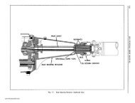
ZINC PLATE<br />
DICHROMATE FINISH ~~<br />
GREENISH WHITE .660<br />
TO BRONZE-LIKE<br />
1<br />
COLOR<br />
5665555<br />
IDENTIFICATION.CJ OR q<br />
GROOVE U tj<br />
5663828<br />
1955<br />
5683101<br />
T<br />
PLAIN<br />
.760<br />
1<br />
STEEL<br />
FINISH<br />
ONO IDENTIFICATION<br />
GROOVE<br />
5665638<br />
Fig. 9-43<br />
Comparison of 1954 and 1955 Power Steering Valve Centering Springs and Plungers<br />
6. Install large bearing race, bearing, and small<br />
bearing race against valve body.<br />
7. Install special spring type washer with concave<br />
face toward bearing and thrust bearing nut loosely.<br />
Use new nut.<br />
8. Worm Bearing Adjustment.<br />
a. Install steering wheel and turn counterclockwise<br />
to stop. Maintain constant pressure on the wheel to<br />
compress plunger springs.<br />
b. Tighten locknut against spring washer (and<br />
spool valve) 20 to 30 lb. ft. torque, making sure the<br />
thrust bearings are properly seated and then back<br />
off nut Y4 to % turn and stake in place. Use crowfoot<br />
wrench tool J -5680 and torque wrench (Fig. 9-45).<br />
To check bearings rotate the gear in each direction,<br />
observing for freedom of movement. Any bind or drag<br />
is indicative of improperly seated bearings.<br />
The pull at the rim of the steering wheel to turn<br />
steering shaft through a 3" arc at the rim will be<br />
approximately Y2 to % lb. This includes seal drag.<br />
c. Remove steering wheel and remove retaining<br />
collar J-5182 from valve body.<br />
seal was removed.<br />
11. Install valve cover, column jacket and gearshift<br />
controls as an assembly. Be sure parts are lined up<br />
as indicated by scribed marks on housing, body and<br />
cover, and install cover attaching screws.<br />
ASSEMBL Y OF <strong>POWER</strong> CYLINDER (FIG. 9-33)<br />
1. Install new seal in adapter if seal was removed.<br />
2. Install "0" ring seals on adapter, if removed.<br />
3. Slide stop plate over piston rod.<br />
9. Install new seal in valve body cover, if seal was<br />
removed, using tool J-5188 (Fig. 9-46).<br />
10. Install "0" ring seal in valve body cover, if<br />
Fig. 9-44<br />
Installing Tool J-5182 on Valve Body Cylinder<br />
www.PontiacSafari.com